
Abstract
For Poly(phenylene sulfide)/Carbon Fiber (PPS/CF) thermoplastic composite laminates, the main purpose of this study was to evaluate effects of “laser” and “plasma” surface treatments on the adhesion performance of primer painting by comparing with “untreated” and traditional “sandblasted” samples. For this purpose, after surface characterization of untreated and treated samples by Wettability, SEM, Surface Roughness, XPS and FTIR analyses; adhesion characteristics of an industrial primer paint applied onto PPS/CF surfaces were evaluated by using two different industrial methods: “Cross-cut Adhesion” tests and “Three-point Bending Adhesion” tests. Compared to the Untreated samples, it was observed that all surface treated samples could be assigned with the “best” primer adhesion grade of GT0. Moreover, surface treated samples had at least two times more maximum “Separation Load” with “cohesive” separation mechanism of primer paint layers. The success of the Sandblasted samples was due to efficient mechanical interlocking mechanism. For the Laser treated samples, adhesion performance was partly due to the mechanical interlocking and partly due to the chemical interactions; while for the Plasma treated samples it was mainly chemical bonding mechanism.
Keywords
Introduction
Painting is a crucial process for aerospace parts in terms of their surface protection, maintenance, operation, performance and appearance. Composite structures especially outer components can be very susceptible to environmental degradation. Paints could extend the life of these composite structures by acting as a barrier to environmental degradation effects of sunlight, rain, moisture and bacteria. Moreover, smooth and well-applied paint can help to improve the aerodynamics of an aircraft by reducing the air drag and decreasing the fuel consumption.
Paints are generally applied as two layers; the first one named as “primer-coat” while the second one “top-coat” in order to achieve ultimate protection. Since surface energies of the thermoplastic aromatic polymer matrices are low, it is difficult for the primer paint to wet their surfaces. Therefore, in order to have certain degree of primer paint adhesion, a kind of surface treatment must be applied to eliminate surface impurities and to enhance wettability by mechanical or chemical techniques. For the thermoplastic matrix composite parts, available methods used in the aircraft industry can be divided in two groups; “traditional mechanical techniques” (such as grinding and sandblasting) and “chemical or energetic techniques” (such as laser and plasma).
Aircraft industry has traditionally utilized mechanical abrasion methods with abrasive-grain sandpapers to polish the surface, get rid of contaminants, and change the surface roughness profile. When the grit size is increased, surface roughness increases proportionally, but with possibility of fiber damages. Sandblasting is a further abrasion method applied, in which stream of mineral particles are aggressively accelerated to the material to activate its surface. Sandblasting results in surfaces with irregular topography and roughness. Similar to grinding, it may also cause fiber damages on the composite surface.
Laser surface treatment is a non-contact, environmentally friendly method that is simple to control and automate. By optimizing the laser parameters (e.g. power, wavelength, pulse distance), especially the surface roughness could be tailored precisely. In order to prevent human error and inconsistent surface characteristics, laser treatment processes can ensure high reliability and repeatability for aerospace structural components.1–4
Plasma surface treatments are used for many polymer surfaces due to leading significant degree of surface activation required in many coating processes including painting. Plasma is a gas of charged and neutral particles containing cations and electrons. Plasma systems create consistent high-density mixture of ions, electrons, free radicals; and direct these reactive species onto the surface, where the charged particles activate or react.5–10
Literature review on the use of “Laser and Plasma Surface Treatments” for Thermoplastic Matrix Composites revealed that, these studies.5,11–21 were mainly concentrated on the improvement of bonding and joining processes. There was no reported study on the use of Laser Treatments to improve primer paint or top-coat paint adhesion, while there were extremely limited number of studies, being only two,22,23 on the use of Plasma Treatments for the Improvement of Primer Adhesion, as summarized below.
Bres et al. 22 applied atmospheric-pressure plasma treatment to increase polymer surface reactivity for strong and long-term paint adhesion on poly(etheretherketone)/carbon fiber (PEEK/CF) composite surfaces. Two operational parameters “scanning speed” (0.3 m/s) and “distance between the nozzle and surface” (27 mm) was kept constant, while changing the “power” parameter for both “air” and “nitrogen” plasma. Treated surfaces were characterized by contact angle wettability measurement, XPS chemical analysis, and AFM topography analyses. Adhesion performance of the paint was characterized by cross-cut adhesion and three-point bending adhesion tests. They indicated that both air and nitrogen plasma treatments improved the paint adhesion to the industrially acceptable high grades of GT0 and GT1 according to cross-cut tests. Maximum load measurements during three-point bending adhesion tests revealed that use of air plasma resulted in top-surface degradation due to oxidation, while use of nitrogen plasma resulted in better paint adherence basically due to surface nano roughness modification.
Lapena et al. 23 studied paint adhesion performance on the carbon fiber reinforced polyaryl ether ketone (PAEK/CF) composite substrate by applying atmospheric pressure “Ar-O2” plasma surface treatment. Water contact angle and XPS analyses were performed to characterize treated surfaces, while cross-cut and three-point bending tests were conducted for paint adhesion. They indicated that use of only cross-cut tests was not appropriate since untreated surfaces also passed the paint adhesion performance with high grades of GT0 and GT1. Then, measurements by three-point bending adhesion tests revealed that Ar-02 plasma treated surfaces had much higher primer and top-coat paint adherence, basically due to the increased levels of the oxygen and nitrogen polar groups. They also concluded that adherence performance of top-coat paint alone (without primer layer) was very high.
It was observed that, in the literature, although there are other PPS/CF related studies10–13 investigating various aspects of thermal behavior, mechanical properties, production and joining of PPS/CF composite structures, no studies were reported on the use of laser or plasma surface treatments to improve primer or top-coat paint adhesion.
Therefore, for the PPS/CF thermoplastic composite laminates, the main purpose of this study was, as the first time in the literature, to evaluate effects of both “laser” and atmospheric “plasma” surface treatments on the adhesion performance of primer painting. Their adhesion performance was also compared with respect to the “untreated” and traditional “sandblasted” samples.
For this purpose, after surface characterization of untreated and treated samples by Wettability, SEM, Surface Roughness, XPS and FTIR analyses; adhesion characteristics of an industrial primer paint applied onto PPS/CF surfaces were evaluated by using two different industrial methods: “Cross-cut Adhesion” tests and “Three-point Bending Adhesion” tests.
Experimental work
Experimental work conducted in this study was composed of five steps; (i) production of PPS/CF laminates, (ii) surface treatments (sandblasting, laser, plasma), (iii) surface characterization (Wettability, SEM, XPS, FTIR), (iv) primer painting, and (v) testing for primer paint adhesion.
Production of PPS/CF Composite Laminates
PPS/CF thermoplastic composite laminates were produced first by supplying their commercially available prepregs, and then consolidating them via compression molding method.
PPS/CF prepregs supplied
Tradename of the supplied PPS/CF prepregs with the thickness of 0.31 mm was Toray-TenCate Cetex® TC1100. Their matrix was a semi-crystalline PPS engineering thermoplastic having glass transition temperature (
Consolidation of PPS/CF prepregs
PPS/CF composite laminates were produced by consolidation of certain number of prepreg layers via compression molding technique. In this method, first prepregs were cut into 55 x 200 mm by using an automated ply cutter. In order to get 2 mm thick laminates, 7 plies were stacked on a mold surface having a polyimide (Kapton) release film. Consolidation above the melting temperature of PPS matrix was achieved by using a hot-pressing system (Langzauner Perfect). Heating, pressing and cooling steps applied were as follows: (i) Increase the press force to 350 kN and the temperature to 315°C, and hold for 30 min (ii) Increase the press force to 550 kN, and hold for 10 min (iii) Cool down to room temperature with 5°C/min ramp.
Surface treatments applied before primer painting
It is known that to improve primer paint adhesion on the surfaces of polymer matrix composite laminates, energetic surface treatments such as “laser” and “plasma” could be applied to form precise surface roughness and chemically active surface functional groups. In this study both of them were used. Moreover, since in the industry, the traditional “sandblasting” method has been still used; effects of laser and plasma treatments would be also compared with the influences of sandblasting.
Before any of these surface treatments, PPS/CF laminates produced were first cut into 100 x 150 mm by using a diamond tip industrial cutter (Diamond-3, 3515RS) with a cooling unit. After cutting, all surfaces were cleaned to get rid of residues by using a solvent (Isopropyl Alcohol, IPA). Thus in this study, laminates investigated and compared could be grouped into four conditions: “untreated”, “sandblasted”, “laser treated”, and “plasma treated”. These surface treatments applied are summarized below.
Sandblasting
In this traditional method, as shown in Figure 1(a), laminate surfaces were sandblasted by using alumina sand particles having average size of 177 µm via a blasting jet gun equipment (8 mm nozzle diameter, 2.5 bar air pressure) at 100 mm distance, 45°-60° projection angle for about 60 s. After sandblasting, laminates were rinsed properly with DI water, and then dried in a furnace at 60°C for 2 h. Equipment used for (a) Sandblasting, (b) Laser and (c) Plasma surface treatments.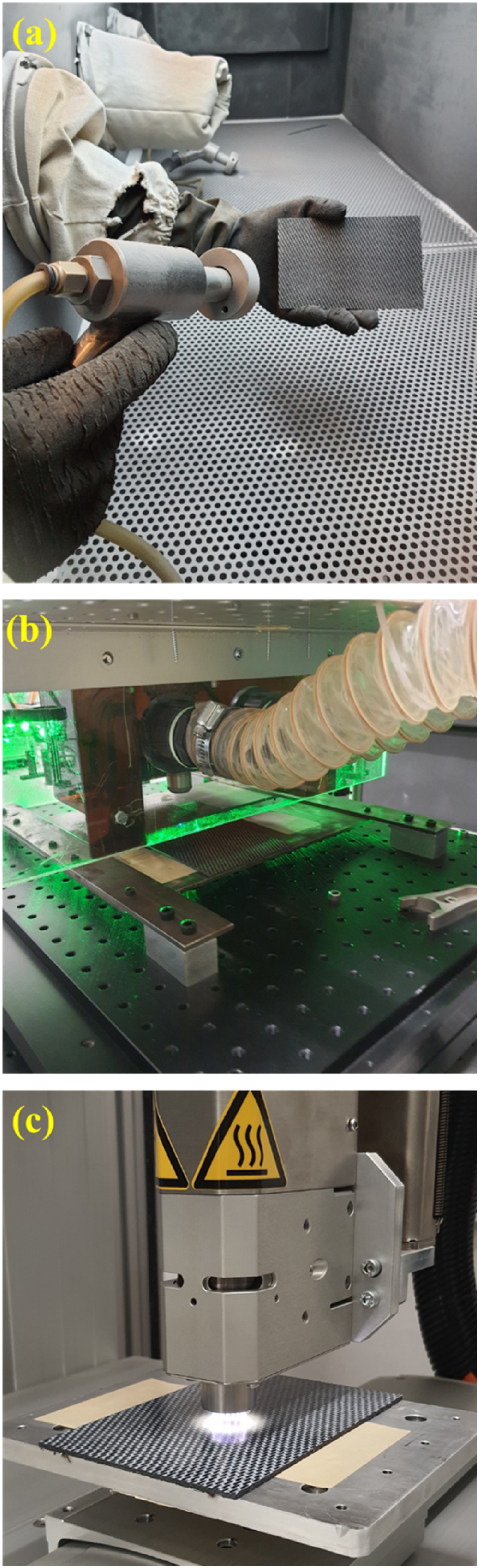
Laser treatment
Laser treatment of the laminate surfaces was conducted, as shown in Figure 1(b), by using the laboratory scale Q-switched Nd-YAG laser set-up (Teknofil, Coherent) generating 266 nm wavelength. Laminates were placed on an X-Y axis controlled table robot (Aerotech, ALS3600); while the laser head was hold steady.
Plasma treatment
As shown in Figure 1(c), plasma treatment of the laminate surfaces was conducted by using a laboratory scale system (Plasmatreat, RD2004) which could operate at atmospheric pressure, therefore treatments done under these systems was also called as “Atmospheric Plasma Treatment”. The system has a rotating plasma jet nozzle that could be controlled by an X-Y-Z axis table robot (HKTM, Toyo). The plasma medium used was “air” plasma.
Characterization of the treated surfaces before primer painting
In order to characterize untreated, sandblasted, laser and plasma treated PPS/CF laminate surfaces, the following four analyses were conducted.
Contact angle measurement and surface energy estimation
Contact angle measurements of untreated and all treated surfaces were achieved by using an optical tensiometer (Biolin Scientific, Attention Theta Lite). First, PPS/CF laminates were placed on the sample platform for high-resolution camera images. Then, sessile drops of 4-5 μl deionized water was placed on the laminate surface. “Water Contact Angles” were measured from the images taken by the camera in accordance with ASTM D7334 standard.
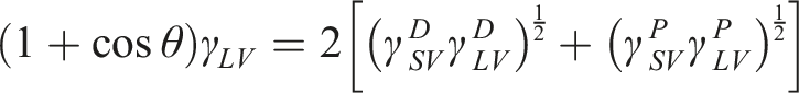
The main objective of contact angle measurement was to estimate “Surface Free Energy” of untreated, sandblasted, laser and plasma treated PPS/CF surfaces in accordance with ASTM D7490 standard. Total surface free energy and its polar and dispersion components were estimated by using the Owens-Wendt-Rabel-Kaelble (OWRK) equation.21,24 given below;

Scanning electron microscopy
Surface morphology of the untreated and treated laminate surfaces was observed under a field emission scanning electron microscope (Zeiss, Sigma 300 SEM) at an accelerating voltage of 5 kV. Since PPS/CF samples have certain level of conductivity, no gold sputtering was necessary.
Surface roughness analysis
Surface roughness of the untreated and treated laminate samples was examined under a contact type MAHR profilometer. Then, surface roughness profile of the samples in accordance with ISO 16,610-21 standard was obtained in terms of Ra roughness, as the average of measurements taken at least from five different regions.
X-ray photoelectron spectroscopy
Chemical composition of the treated laminate surfaces was investigated by X-ray photoelectron spectroscopy (Thermo Fisher Scientific, K-Alpha). For the emission of photoelectrons with element-specific binding energies, surfaces were scanned under monochromatic Al-Kα radiation (1486.7 eV).
Fourier-transform infrared spectroscopy
Fourier-transform infrared spectroscopy (Perkin Elmer, Spectrum One) was used in order to reveal formation of functional groups on the surfaces of treated laminate samples. At least 32 scans were signal-averaged by the diamond attenuated total reflectance (Di-ATR) unit of the spectrometer in the wavenumber range of 650-4000 cm−1 with a resolution of 4 cm-1.
Primer painting of treated surfaces
In this study, primer paint system used was a three-component epoxy based commercial primer (Akzo Nobel, Aerodur Barrier Primer 37,045), compatible with a wide range of composites and polymers. This white-colored primer has low water permeability with high resistance to aircraft hydraulic fluids and other chemicals.
Main steps used during primer application onto the surface treated PPS/CF laminate samples are illustrated in Figure 2. First, in order to disperse all pigments present in the base primer uniformly, it was stirred in a shaker. Then, 50 parts hardener was added to the 100 parts base epoxy, and stirred again thoroughly. For the required level of viscosity, 100-125 parts thinner was added eventually. Primer painting of surface treated PPS/CF laminate samples: (a) Stirring the base epoxy primer, (b) Mixing the base primer with hardener and thinner, (c) Surface treated laminates before primer application, (d) Primer painting by a spray gun mechanism, (e) Curing/drying after primer application, and (f) An example of primer painted laminate sample.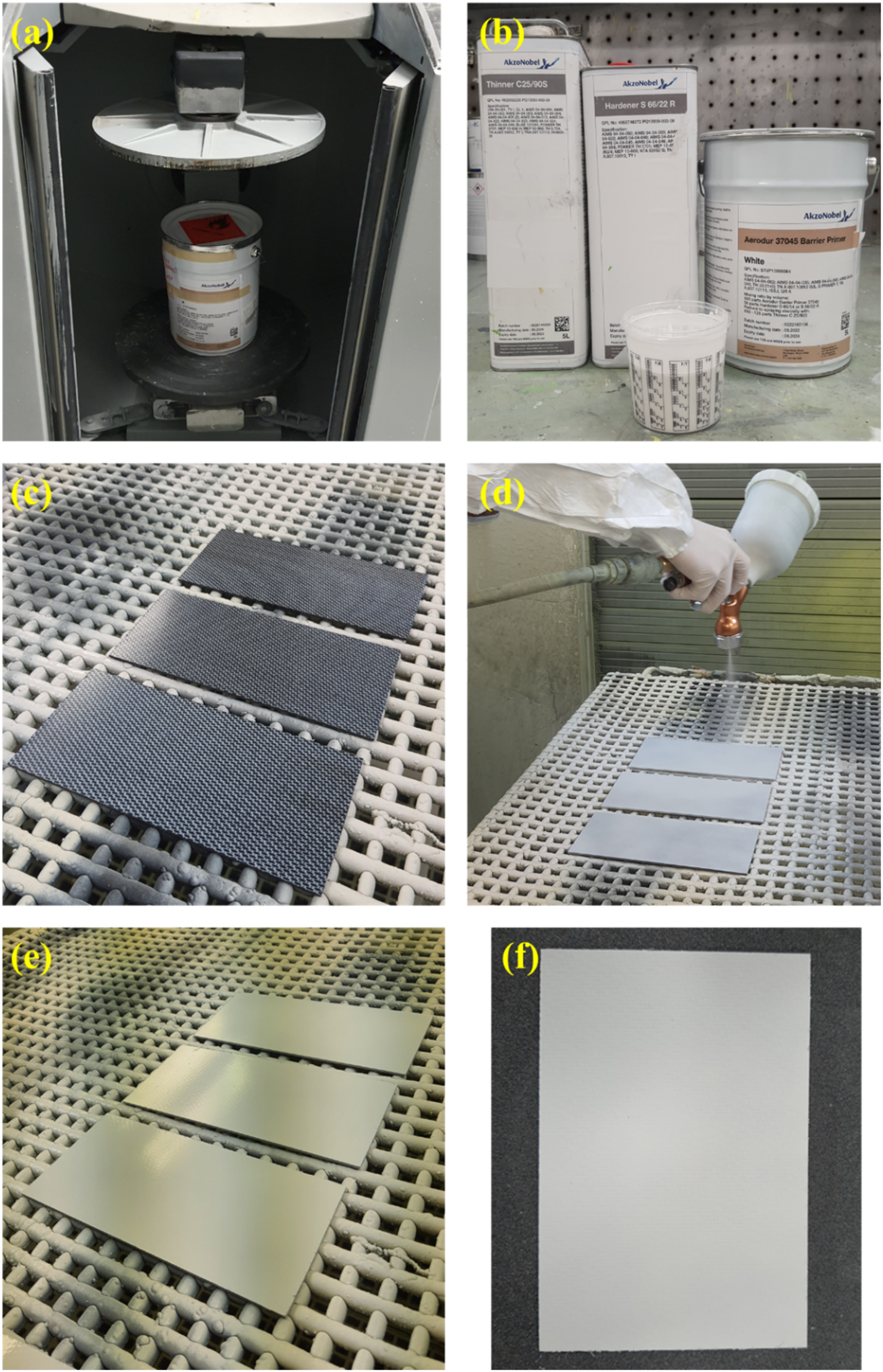
Primer mixture was applied onto the treated laminate surfaces by using a spray gun mechanism, successively; so that the approximate primer thickness would be 20 µm. After primer spraying, laminate samples were cured/dried in a room at 60° for 2 h.
Testing for adhesion performance of primer paint
In this study, in order to evaluate effects of all surface treatments on the primer paint adhesion performance; two different standardized industrial testing techniques were used: “cross-cut” and “three-point bending” adhesion tests.
It should be noted that, in the industry, primer and top-coat paint adhesion tests were conducted usually in two different conditions; the first one being just after the painting operations, while the second one is after immersing the painted specimens in water for a certain period. According to ISO-2812 standard, painted specimens should be immersed in de-ionized water for 7 or 14 days. Therefore, in this study all primer adhesion performance tests were conducted “before” and “after” 7 days of water immersion.
Cross-cut adhesion test
This test is a qualitative approach to evaluate the resistance of primer paint against separation from composite laminate surface, when a right-angle lattice pattern was cut into the primer layer. As shown in Figure 3, by using a hand-held multi-blade cross-cutting device (Elcometer 1542, 6 teeth, 1 mm), six parallel cuts were formed in two directions making a lattice pattern in accordance to ISO-2409 standard. Cross-cut primer adhesion test: (a) and (b) Formation of cross-cut lattice pattern by vertical and horizontal cutting, (c) and (d) Cleaning of the primer residues from the cutting area by brushing and adherent tape removing, (e) and (f) Inspection of the lattice pattern under a magnifier, and comparing the appearance with the ones given in the standard table.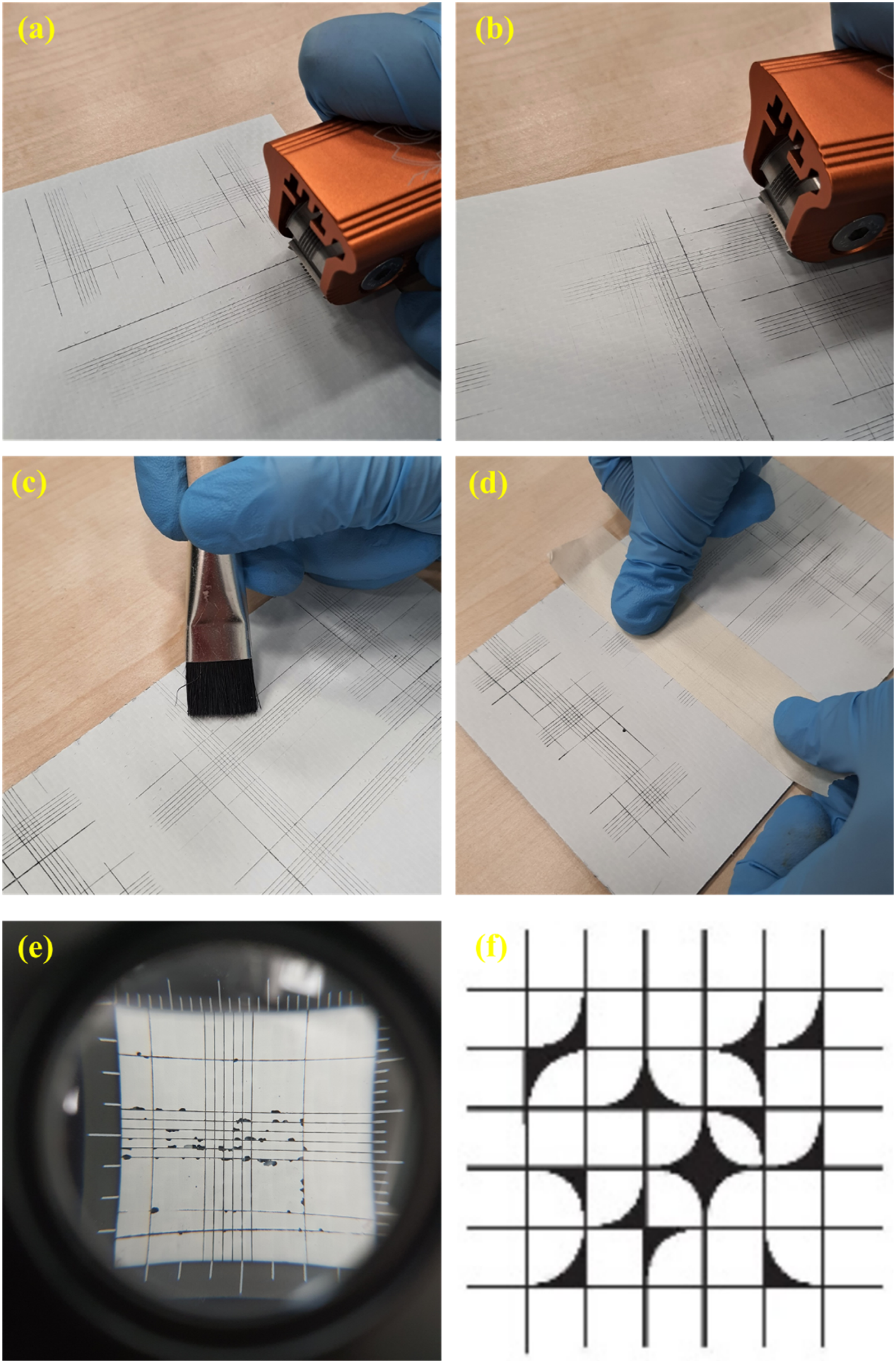
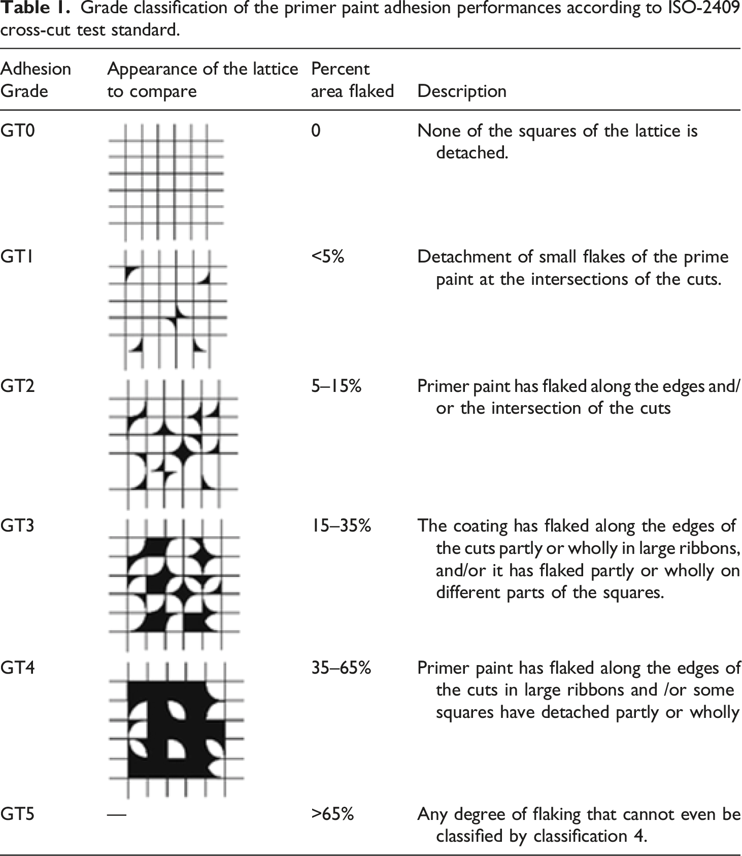
Grade classification of the primer paint adhesion performances according to ISO-2409 cross-cut test standard.
Three-point bending adhesion test
Compared to cross-cut test, that test is rather a quantitative approach to evaluate the resistance of primer paint against separation from the composite laminate surface under three-point loading. As shown in Figure 4, first on the center of the 2x10x50 mm primer painted laminate specimen, a thermosetting (Loctite EA 934NA AERO) rigid block of 4x5x25 mm was molded in accordance with ISO 14,679 standard. Three-point bending primer adhesion test: (a) Specimen configuration used, (b) Molding of thermosetting rigid block on the center of primer painted surface, (c) The whole specimen to be loaded, (d) Three-point bending loading during the test, (e) Separation of the primer paint layer together with the rigid block, and (f) Inspection of the separated interface.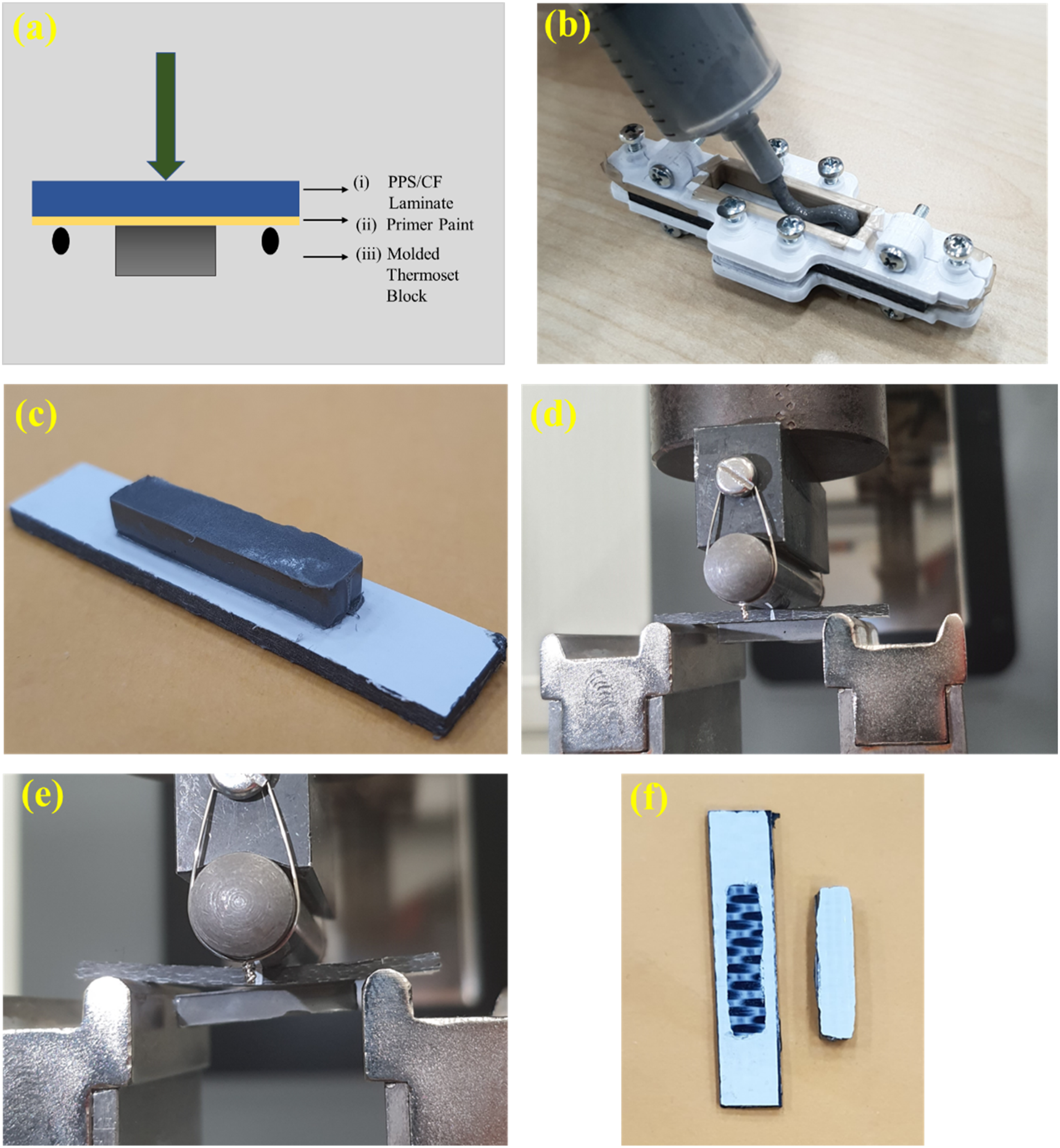
Then, the whole specimen was three-point bending loaded by using a 10 kN Universal Testing System (Instron 68TM) with a span length of 33 mm. After separation of the primer paint layer together with the rigid block at the center, primer adhesion performance was evaluated first by visual inspection of the surfaces, and then quantitively by recording the maximum load reached in the load-deflection curve.
Results and discussions
In this section, first, preliminary laser and plasma surface treatment trials to determine their process parameters were explained. Then, effects of all surface treatments on the chemical and morphological characteristics of the surfaces were discussed. Finally, influences of all treatments on the primer paint adhesion performance were elaborated.
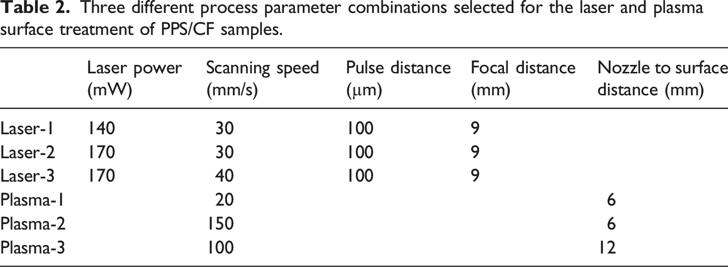
Trials for the laser and plasma surface treatment parameters
In the laser surface treatment equipment used, it was possible to change “four” processing parameters. Therefore, in order to observe influences of these four parameters, several different combinations were tried. For instance; for the “Laser Power” parameter, values of 100, 140, 170, 200 mW; for the “Laser Scanning Speed” parameter, values of 30, 40, 50 mm/s; for the “Laser Pulse Distance” parameter, values of 100, 200 µm; for the “Laser Focal Distance” parameter, values of 9, 10, 11 mm were used. Thus, the total number of trials having different combinations of the parameters were 48.
In the atmospheric plasma surface treatment equipment used, it was possible to change “two” processing parameters. Therefore, in order to observe influences of these two parameters, different combinations were tried. For example; for the “Plasma Scanning Speed” parameter, values of 5, 20, 100, 150 mm/s, and for the “Plasma Nozzle Distance” parameter, values of 6, 12, 24 mm were used. Thus, the total number of trials having different combinations of the parameters were 12.
Then, in order to choose three different process parameter combinations for each surface treatment method, “contact angle” measurements and “surface free energy” estimations were conducted for the 48 different laser treatment trials and 12 different plasma treatment trials.
It is known that for the sufficient primer paint adhesion on the composite laminate surfaces, it is preferable to have “lower contact angle” and “higher surface energy” values. Therefore, the first elimination of the trials was done from this perspective.
Moreover, it is also known that surface treatments should not lead to severe physical damages on the composite laminate surfaces, such as “complete matrix removal”, “fiber stripping”, and “fiber damage”. Thus, the second elimination of the trials was done by examining the treated surfaces under scanning electron microscope (SEM).
Three different process parameter combinations selected for the laser and plasma surface treatment of PPS/CF samples.
Effects of treatments on the surface characteristics of the samples
In order to observe effects of laser and plasma treatments on the various chemical and physical characteristics of the PPS/CF laminate surfaces, four different analyses (Contact Angle-Surface Energy, SEM, XPS, FT-IR) were conducted for “Laser-1, Laser-2, Laser-3” and “Plasma-1, Plasma-2, Plasma-3” samples one by one. Of course, each analysis was also conducted for the “untreated” and the traditional “sandblasted” samples for comparative purposes.
Wettability analyses of the untreated and treated surfaces
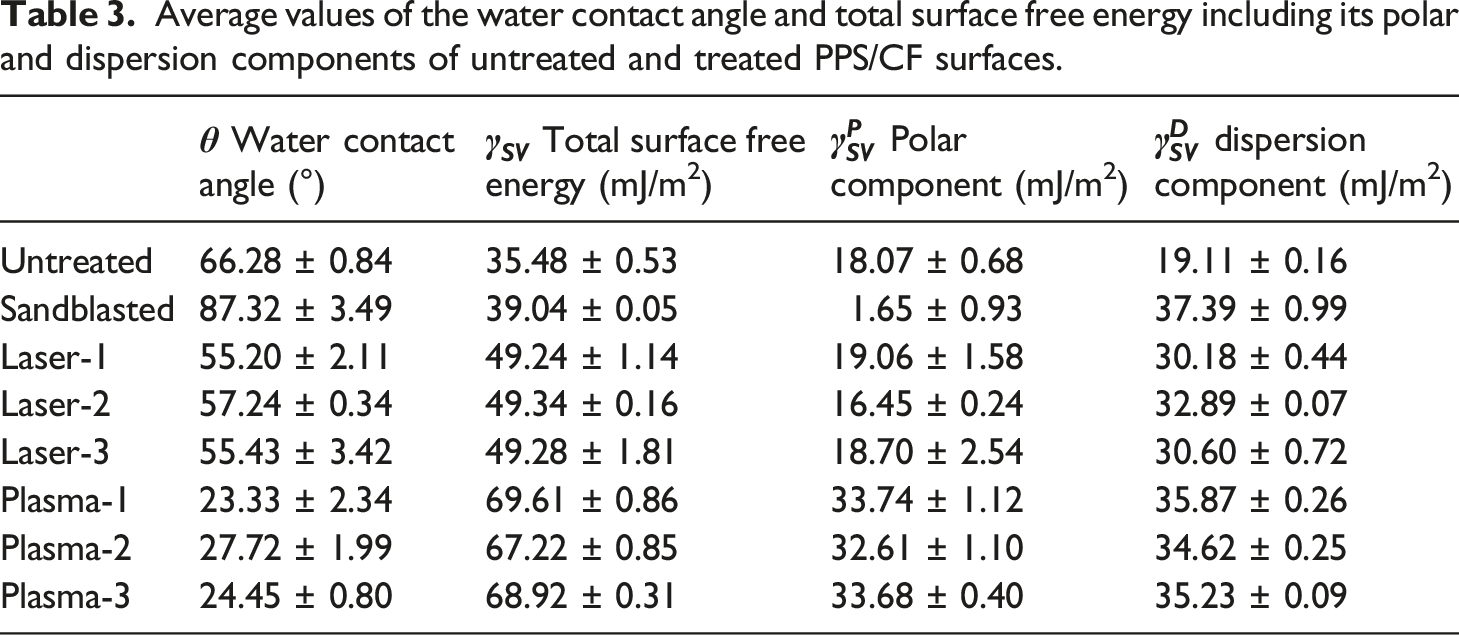
Average values of the water contact angle and total surface free energy including its polar and dispersion components of untreated and treated PPS/CF surfaces.
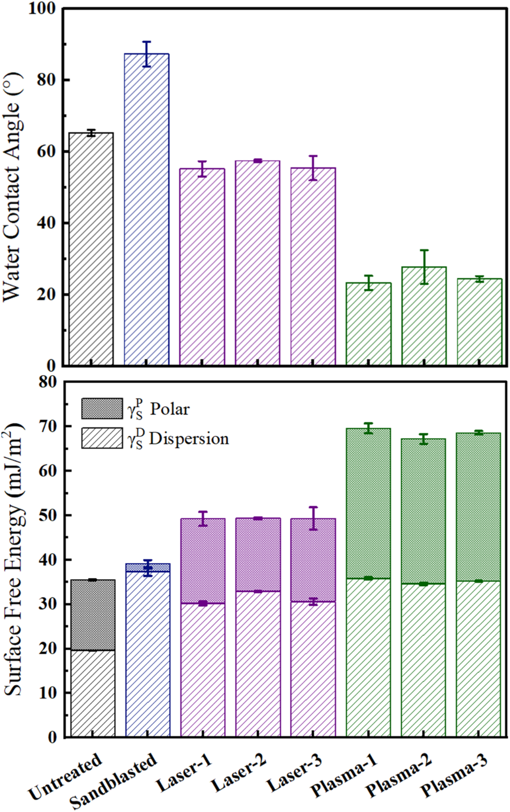
Water contact angle and total surface free energy including its polar and dispersion components of untreated and treated PPS/CF surfaces.
For the spontaneous wetting condition, it is known that a decreasing trend in the Contact Angle values play an important role. As shown in Table 3 and Figure 5, Contact Angle values of Untreated sample increased from 66° to 87° in the Sandblasted sample. On the other hand, in the Laser and Plasma treated samples, significant decreases were observed; for example, in Laser-1 treated sample the angle decreased to 55°, for the Plasma-1 treated sample it was as low as 23°.
Apart from importance of lower Contact Angle values, Surface Free Energy values of the solid surfaces should be as much as higher for efficient wetting and adhesion of the liquid medium. Table 3 and Figure 5 indicated that total Surface Free Energy of the Untreated sample slightly increased from 37 mJ/m2 to 39 mJ/m2 for the Sandblasted sample. For the Laser and Plasma treated samples increases were more significant. For instance, the increases were up to 49 mJ/m2 for the Laser-1 and as much as 69 mJ/m2 for the Plasma-1 treated samples.
It was also known that,5,21,25 the degree of “Polar Component” in the total Surface Free Energy values act as a driving force for the wettability and more significantly for the intermolecular chemical interactions leading to improved adhesion on the solid surfaces. It was seen that Polar Component of the Untreated sample was 18 mJ/m2, which almost diminished in the Sandblasted sample. No significant changes were observed in the Laser treated samples; on the other hand, increases for the plasma treated samples were as much as up to 33 mJ/m2.
SEM and surface roughness analyses of the untreated and treated surfaces
Since surface morphology of the composite laminates also influences primer paint adhesion, SEM analyses were conducted on different locations of all sample surfaces. Figure 6 displays examples of 500x magnification SEM images taken from the Untreated and Treated PPS/CF surfaces. In Figure 6, it was very apparent that, there was an enormous increase in the surface roughness of the Sandblasted sample surface with certain degree of “fiber stripping” and “fiber damage”. On the other hand, compared to the morphology of Untreated surface, it was seen that 500x magnification SEM images were not suitable to observe the degree of surface roughness after laser and plasma treatments. Examples of the SEM images for the Untreated and Treated PPS/CF surfaces (Magnification = 500x).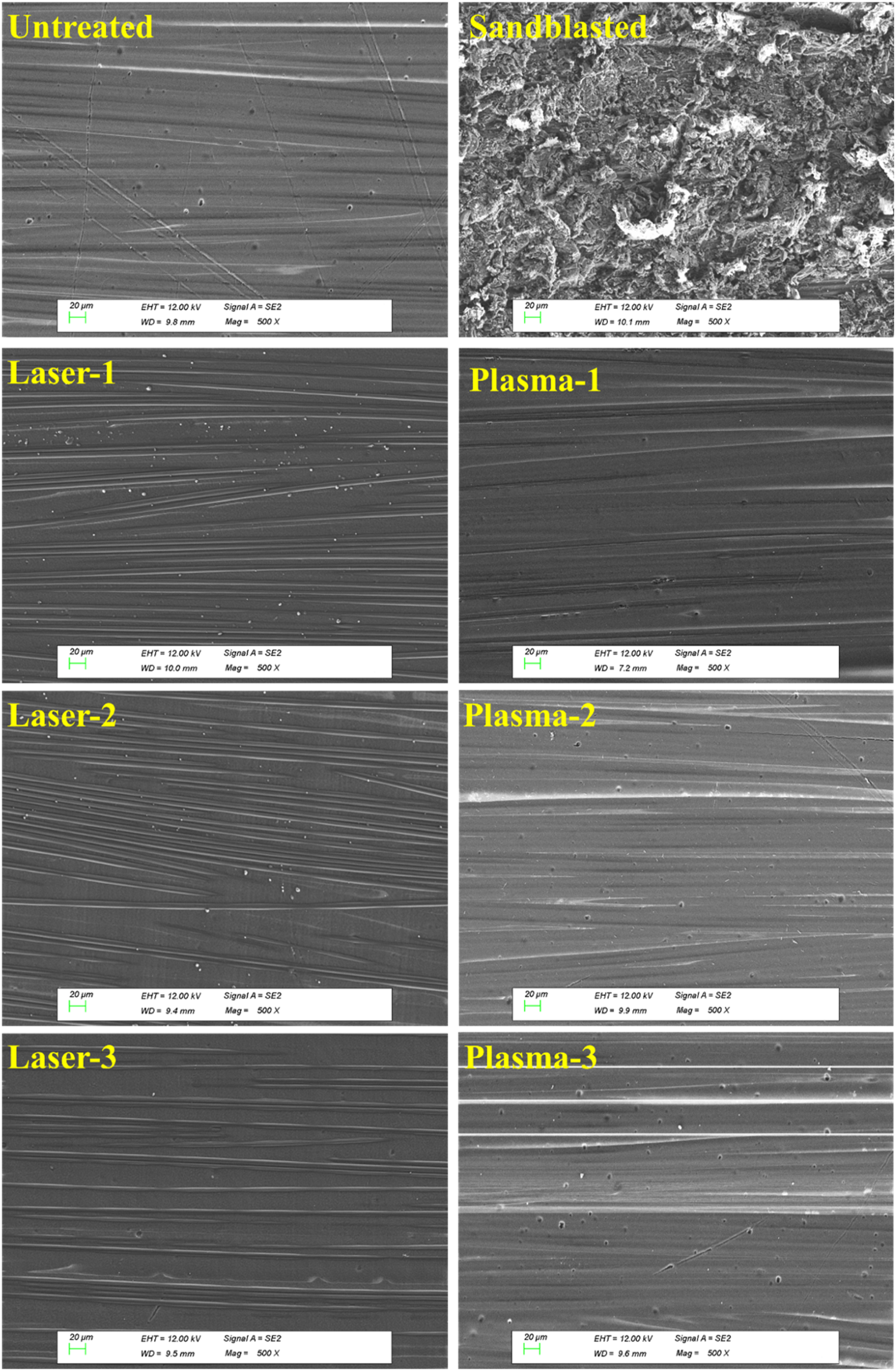
Since surface roughness of PPS/CF laminates play a significant role especially on the mechanical interlocking mechanism, it was necessary to conduct a kind of quantitative surface roughness analysis. For this purpose, surface topography of untreated and treated samples was examined under a contact type profilometer. In Figure 7, average values in terms of compared. It was observed that Ra surface roughness value of Untreated sample increased enormously from 0.48 μm to 4.41 μm in the Sandblasted sample, i.e. an increase of more than 9 times. Surface roughness Ra of the untreated and treated PPS/CF surfaces.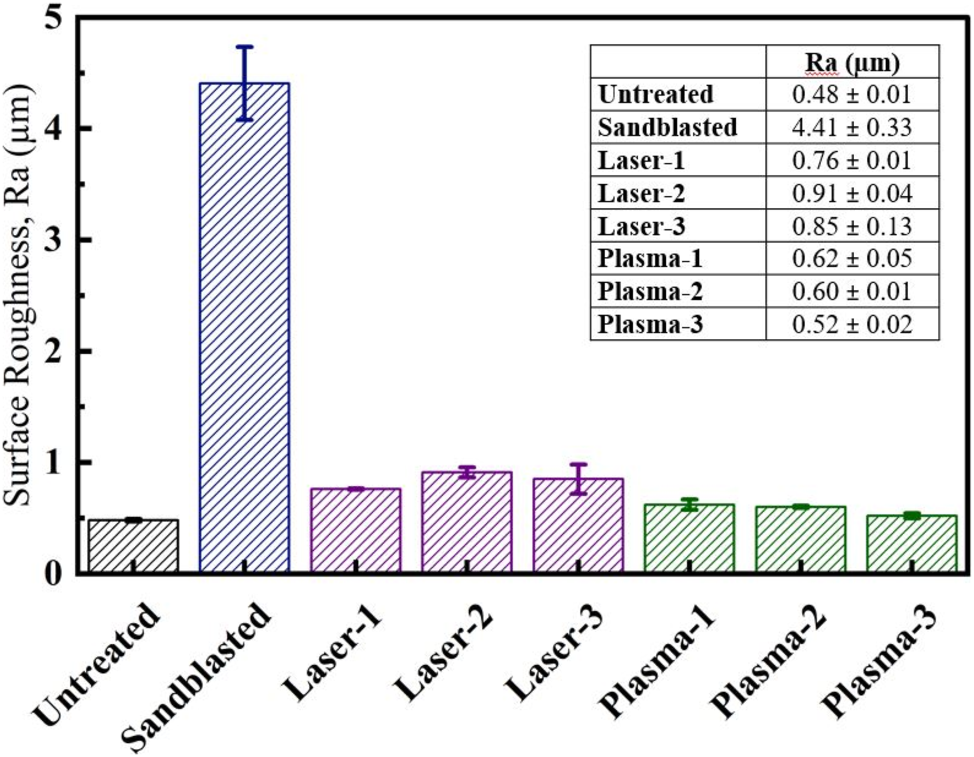
Consequently, this traditional mechanical surface treatment method has been still used before primer painting operations of composite aircraft parts. Because, significant increase in the micro level surface roughness also increases wettable surface area and enable mechanical interlocking at the interface, improving the adhesion between the composite laminate surface and the primer paint.
Figure 7 also indicated that the increase in Ra surface roughness value of Laser treated samples were up to around 0.9 μm, i.e. around 87% increase. Thus, it could be interpreted that mechanical interlocking bonding mechanism would be also a part of the efficiency of Laser treatment on the primer paint adhesion. On the other hand, the increase in Ra surface roughness value of Plasma treated samples were to 0.6 μm (only 25% increase), thus it was difficult to interpret influence of mechanical interlocking bonding mechanism.
XPS analyses of the untreated and treated surfaces
Chemistry of the composite laminate surfaces is another important factor for the adhesion of primer paints. Thus, XPS analyses were conducted on both resin rich and fiber rich regions of Untreated and Treated PPS/CF surfaces. Figure 8 indicated that XPS spectra of the Untreated sample, i.e. PPS matrix basically consisted of three elements; carbon (C 1s) at 285.1 eV, sulphur (S 2p) at 164.1 eV, and oxygen (O 1s) at 532.1 eV; which are consistent with the previous studies.10,26,27 Figure 8 revealed that for the Sandblasted and all Laser treated samples no new peaks appeared, but in the Plasma treated samples a minor peak for nitrogen (N 1s) at 402.1 eV formed. XPS spectra of the untreated and treated PPS/CF surfaces.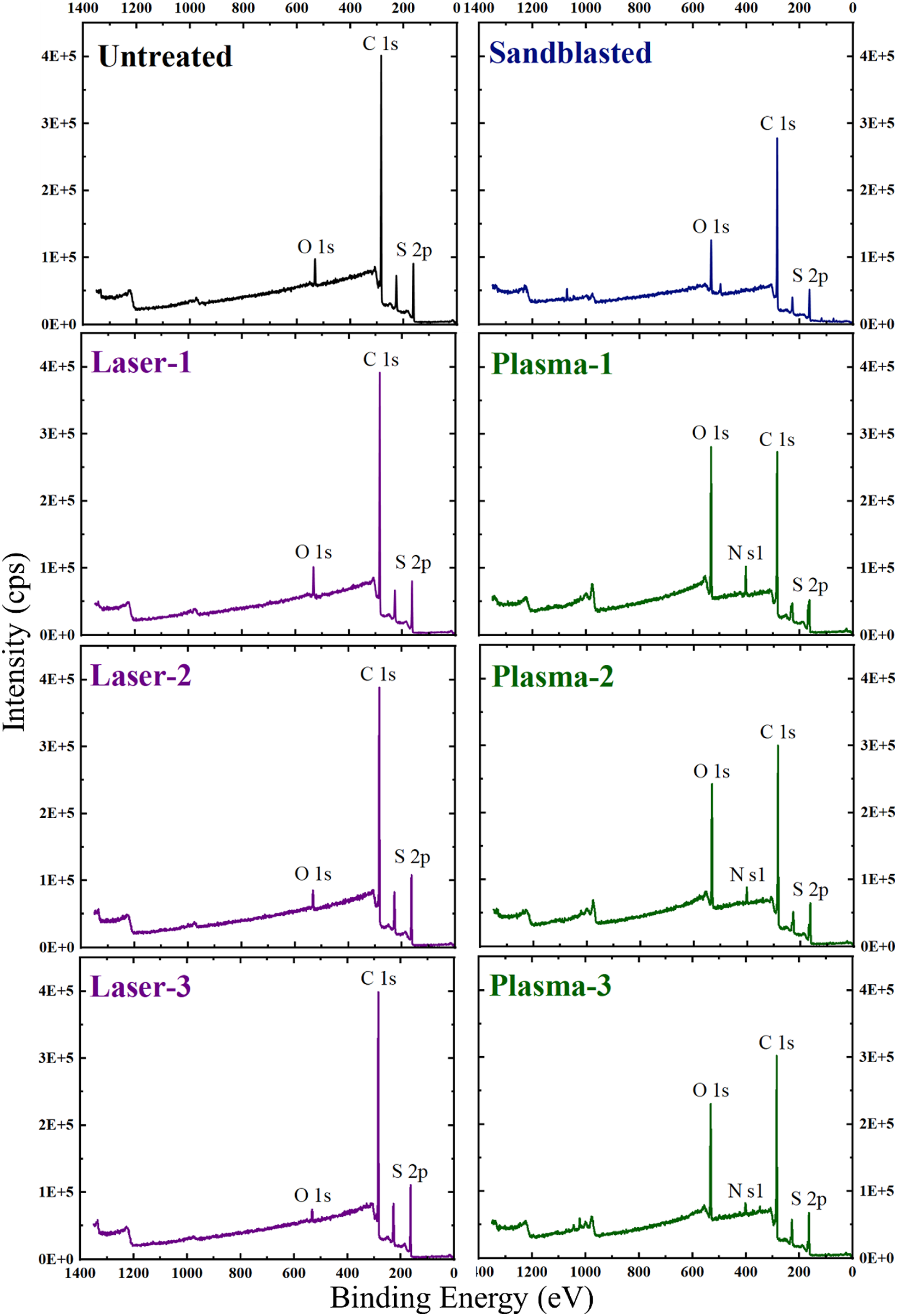
Elemental compositions together with o/c and o/s atomic ratios of the untreated and treated PPS/CF surfaces determined by XPS analyses.
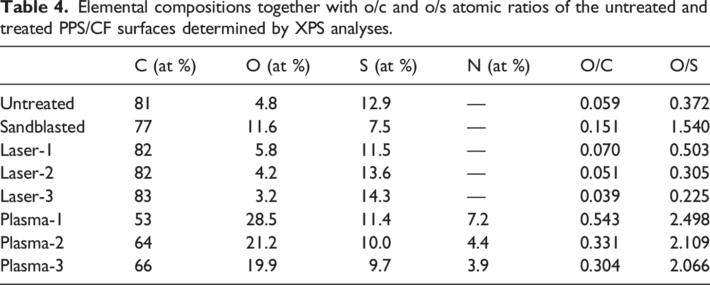
It was seen that both O/C and O/S atomic ratios of the Untreated sample remained almost unchanged in the Laser treated samples; contrarily, significant increases were observed in the Plasma treated samples.
For example, O/C atomic ratio of the Untreated surface increased from 0.059 to 0.543 in the Plasma-1 treated surface, while this increase in O/S atomic ratio was from 0.372 up to 2.498. Thus, it could be interpreted that both C and S elements in the PPS structure oxidized significantly after Plasma treatments.
Consequently, to reveal these oxidized polar groups on the surfaces of Plasma treated samples, both C 1s and S 2p main peaks were deconvoluted. Figure 9 compares C 1s and S 2p main peaks of the Untreated sample and their deconvoluted form for the Plasma-1 treated sample. It was observed that Plasma treatment resulted in formation of three new peaks under C 1s envelope, representing oxidation bonds of C-O at 286.6 eV, C=O at 288.3 eV, and O=C-O at 289.4 eV. Similarly, in S 2p deconvolution, two new peaks were appeared under its envelope, representing the oxidation bonds of S=O at 166.1 eV and O=S=O at 168.4 eV.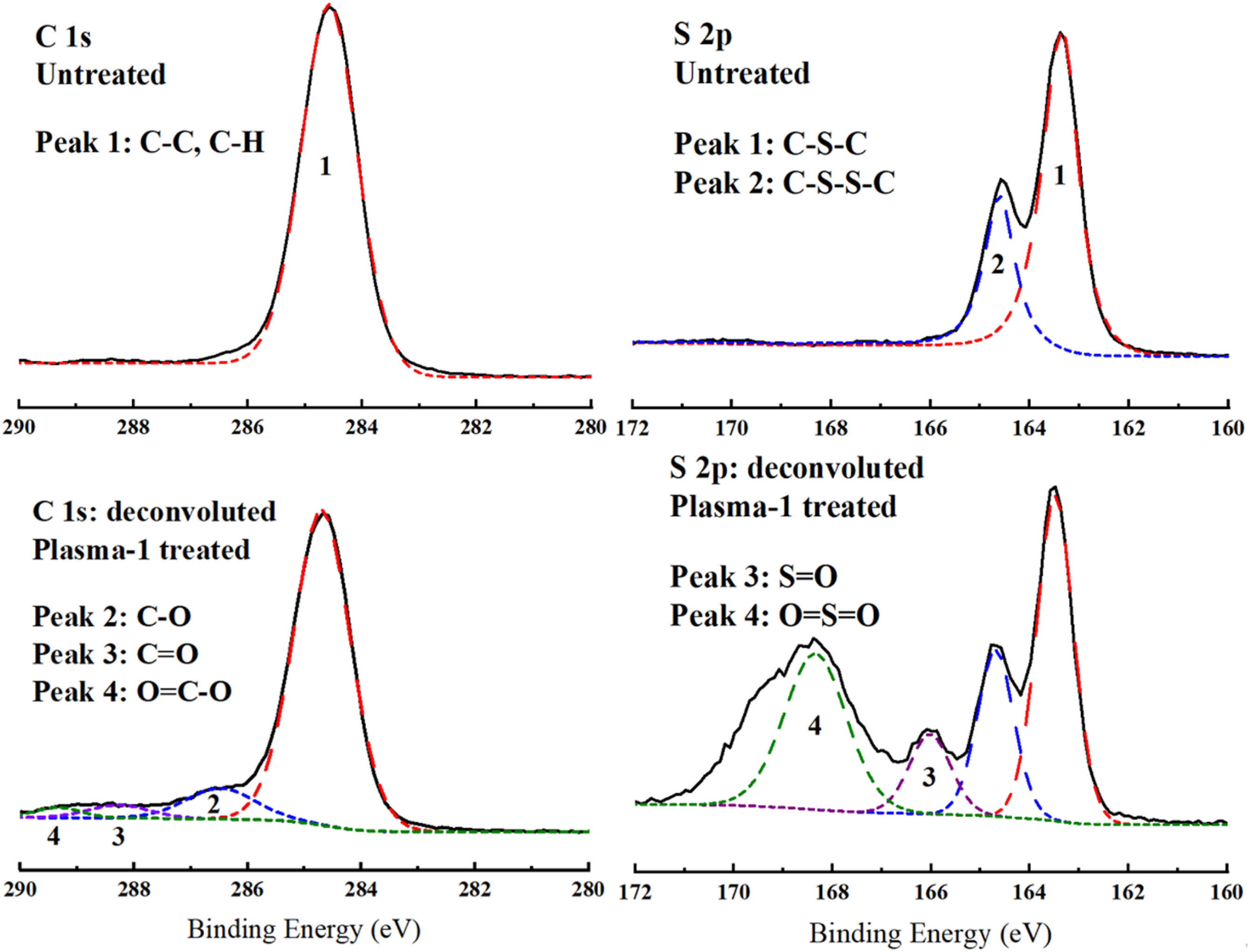
Therefore, it could be pointed out that Plasma surface treatment increased the number of polar groups on the PPS/CF surfaces, which might improve primer paint adhesion via chemical bonding mechanism.
FTIR Analyses of the untreated and treated surfaces
FTIR analysis was the second technique used for the chemical characterization of the Untreated and Treated PPS/CF surfaces. As shown in Figure 10, it was observed that there were no apparent differences between the spectrum of Untreated sample and spectra of the Laser treated samples. Then, due to higher possibility of changes in the Plasma treated samples, spectrum of Untreated and Plasma-1 treated samples were compared in Figure 11 in detail by magnifying the scales of the axes. FTIR spectra of the untreated and treated PPS/CF surfaces. Details in the FTIR spectrum of the Untreated and Plasma-1 treated PPS/CF surfaces.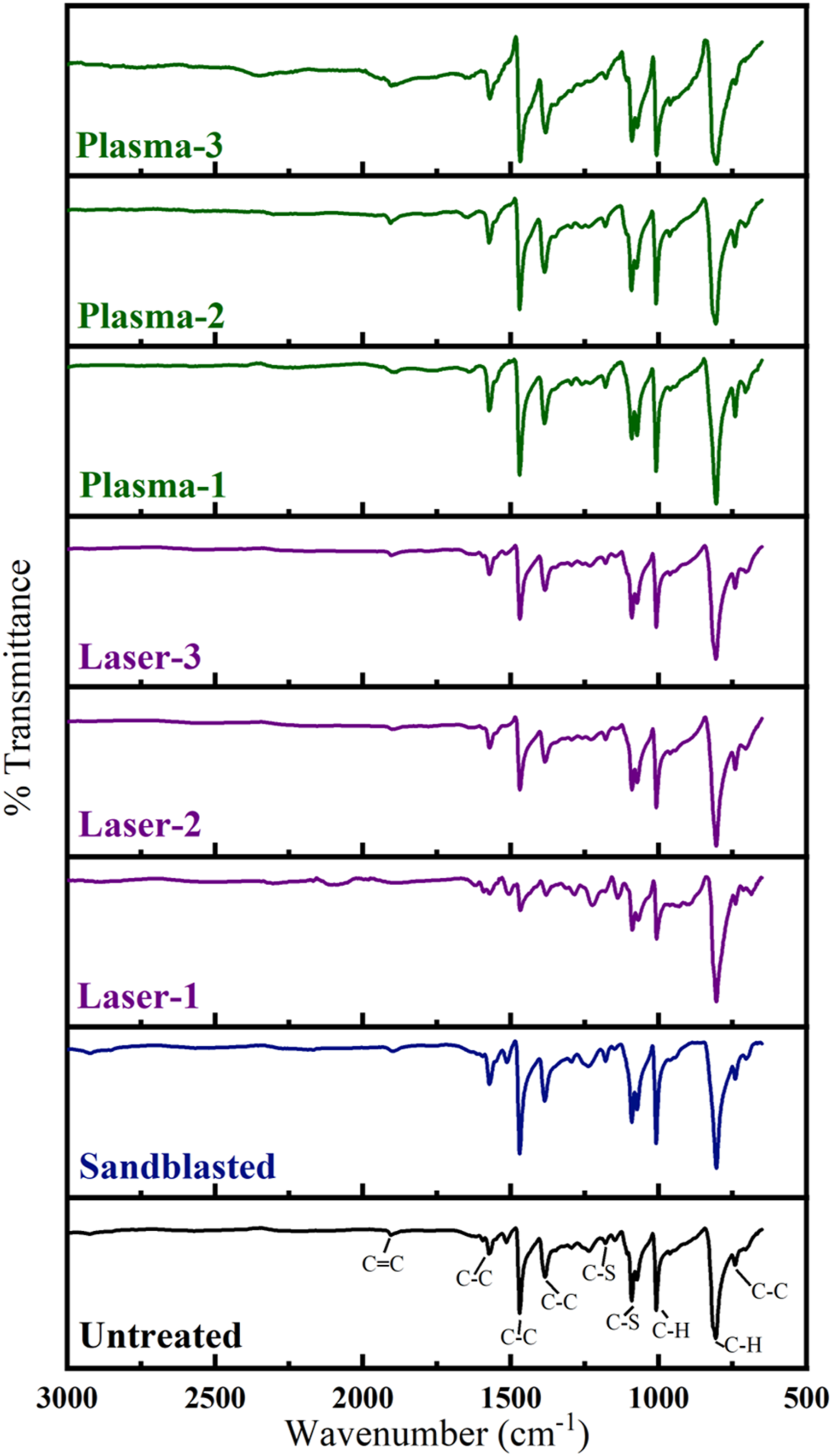
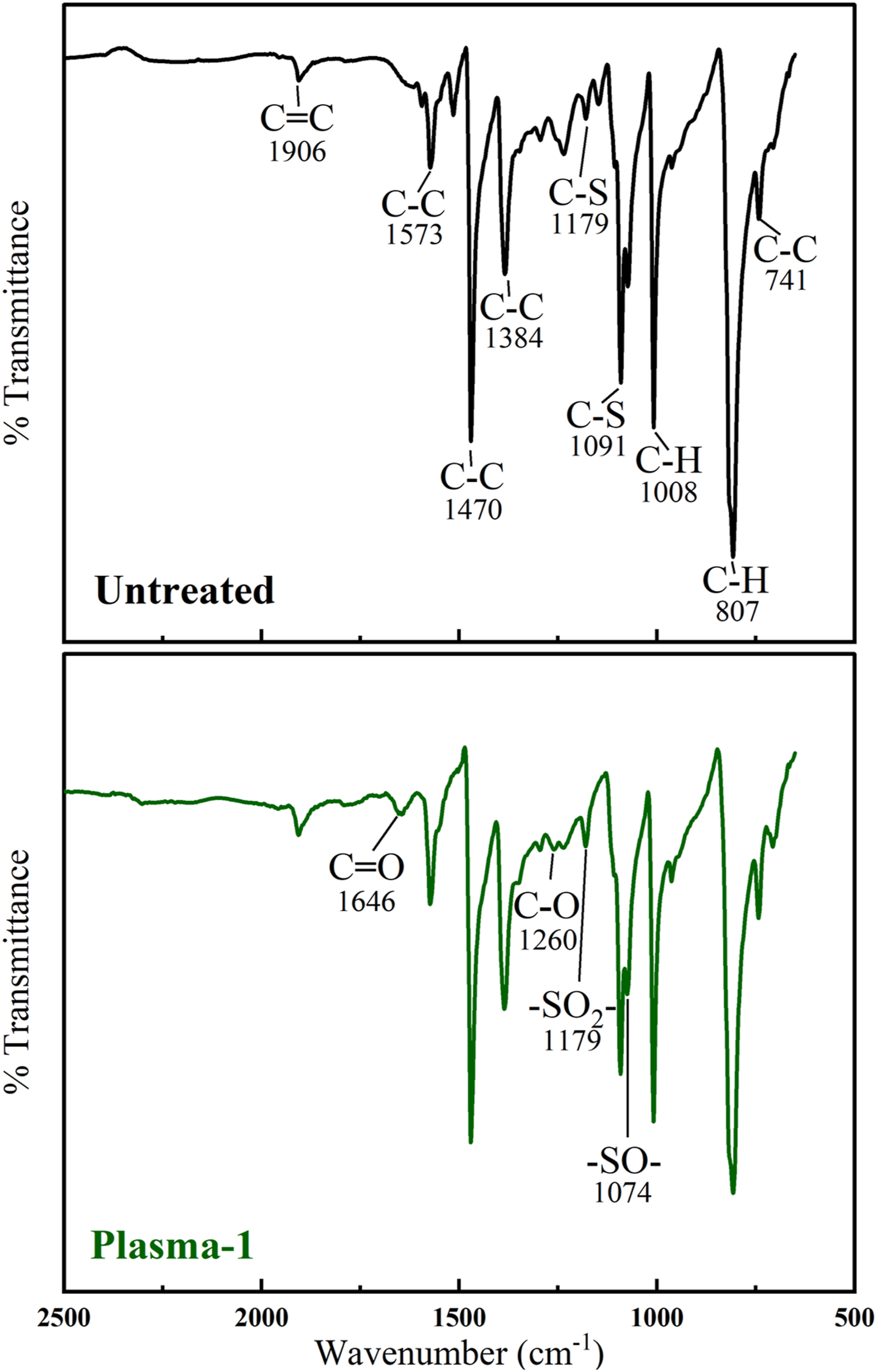
The first spectrum in Figure 11 presents details of the typical peaks for the Untreated sample, i.e. PPS matrix. It is known that,27–29 characteristic IR peaks of PPS at 1573, 1470, 1384 cm−1 are attributed to the stretching vibration of C-C bonds in benzene ring, while the peak at 1091 cm−1 is assigned to the stretching vibration of the C-S bond. The strong peak at 807 cm−1 is the characteristic C-H of the benzene ring.
The second spectrum in Figure 10 was constructed by magnifying the scales of the Plasma-1 sample spectrum in order to reveal possible changes due to the oxidation of PPS matrix. Batista et. al. 28 pointed out that the peaks in the range 1800-1600 cm−1 were attributed to the carbonyl (C=O) stretching, while the peaks in the range 1300-1100 cm−1 were for the C-O bonds formed during oxidation. In this study, tiny peaks for C=O appeared at 1646 cm−1, while for C-O appeared at 1260 cm−1. Moreover, Xing et. al. 27 discussed that after oxidation, peaks for the stretching vibration of –SO2– and –SO– form at 1178 and 1075 cm−1, respectively. In this study, these tiny peaks appeared at 1179 and 1074 cm−1, respectively.
Thus, it could be stated that formation of these chemically reactive sites, i.e. C=O, C-O, –SO2–, –SO–, after Plasma surface treatments, might improve primer paint adhesion on the PPS/CF composite laminates via chemical bonding mechanism.
Effects of treatments on the primer paint adhesion
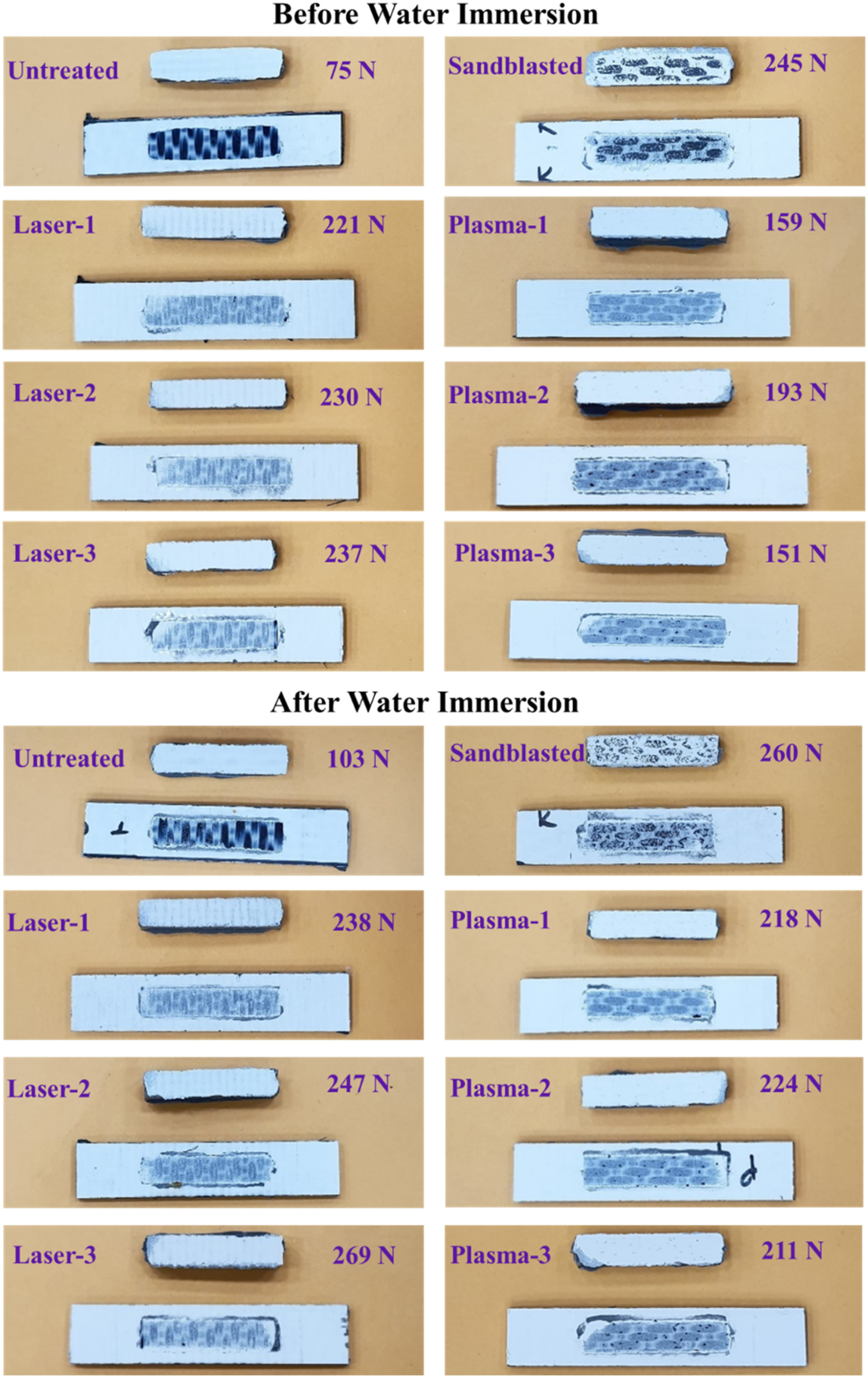
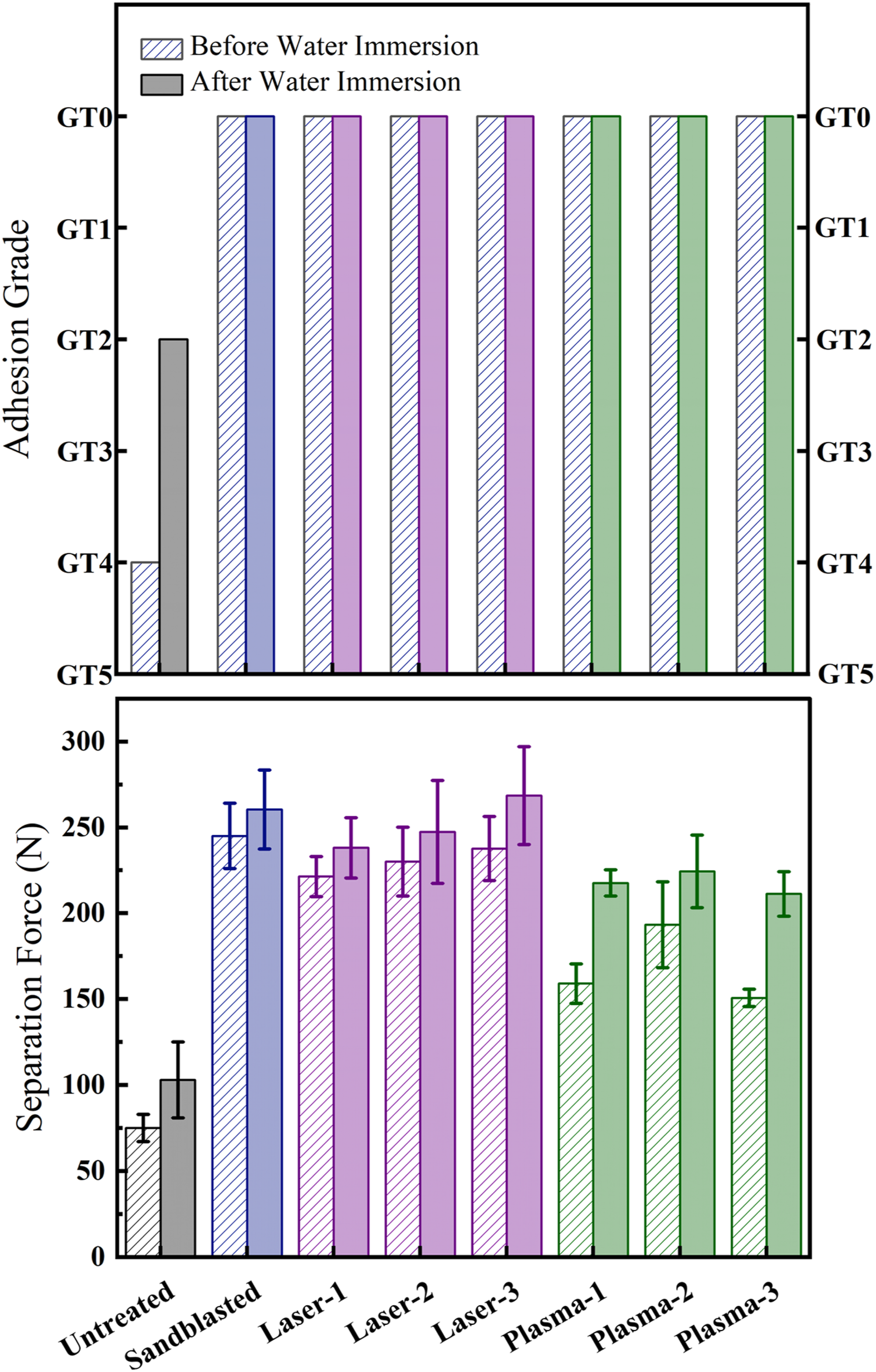
After surface characterization of all untreated and treated PPS/CF composite laminates, primer paint adhesion on these surfaces were evaluated by conducting two different standardized industrial testing techniques, i.e. “cross-cut” and “three-point bending” adhesion tests. Results of these tests for all samples were illustrated in Figures 12 and 13, separately. Then, their results were compared in Figure 14. Appearances of the cross-cut lattice patterns including assigned adhesion grades of untreated and treated PPS/CF surfaces “before” and “after” water immersion. Appearances of the separated surfaces including maximum separation loads obtained by three-point bending tests of untreated and treated PPS/CF surfaces “before” and “after” water immersion. Comparison of cross-cut and three-point bending adhesion test results for untreated and treated PPS/CF surfaces “before” and “after” water immersion.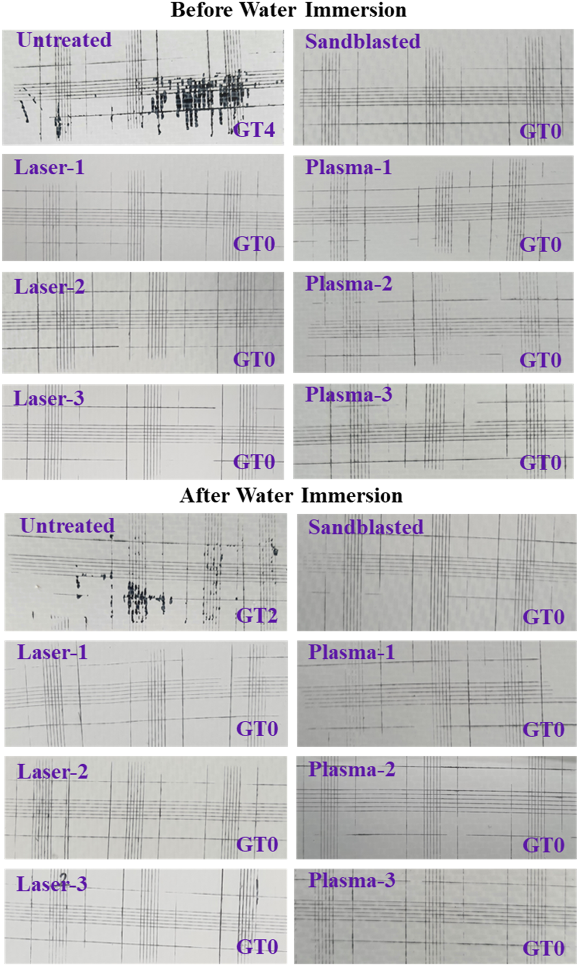
It should be pointed out that, in the industry, primer and top-coat paint adhesion tests were generally repeated for two conditions; the first one being just after the painting operations, while the second one is after immersing the painted specimens in water for a certain period. Because, testing after water immersion is considered to be very useful for predicting their service performance. Therefore, in this study, all primer adhesion tests were first of all conducted for the samples just after primer painting operations, and these samples were designated as “before water immersion”. Then, all tests were repeated for another group of primer painted samples which were this time immersed in deionized water for 7 days, thus those specimens were designated as “after water immersion”.
Adhesion performance according to cross-cut tests
As explained in the experimental work section in detail, lattice patterns were cut into the primer paint layer by using a hand-held multi-blade cross-cutting device. Then, a kind of qualitative evaluation for the resistance of primer paint against separation from composite laminate surfaces were conducted. After cleaning the primer paint residues from the area of cutting, appearances of the lattice patterns were inspected under a magnifier, and then compared with adhesion grade classification table given by the standard, i.e. Table 1. Eventually, depending on the degree of primer paint flaking from the cross-cut lattice patterns, primer adhesion performance was graded as GT0, GT1, GT2, GT3, GT4, GT5. The “highest” or “best” adhesion grade is assigned with GT0, while GT5 represents the “lowest” or “worst” adhesion grade; in which industrially acceptable adhesion grades are only GT0 and GT1.
Figure 12 illustrates appearances of the cross-cut lattice patterns for all untreated and treated sample surfaces “before” and “after” water immersion, together with their adhesion grades (GT) assigned by comparing the appearances given in the standard (Table 1). It was revealed that all surface treated (sandblasted, laser and plasma treated) PPS/CF samples, both “before” and “after” water immersion, were assigned with the “best” adhesion grade of GT0. On the other hand, due to the significant degree of primer paint separation, i.e. large amount of detachment of primer paint flakes from their cross-cut lattices, Untreated samples were assigned with very low adhesion grades, being only GT4 and GT2 for the “before” and “after” water immersed samples, respectively.
Adhesion performance according to three-point bending tests
In comparison to cross-cut adhesion test, three-point bending test is considered a more quantitative one for the determination of adhesion performance. As explained in the experimental work section in detail, in order to evaluate resistance of the primer paint against separation from the composite laminate surfaces, a smaller thermosetting rigid block was molded onto the center of three-point bending specimens prepared from the untreated and treated, and then primer painted PPS/CF samples. Then, the whole specimen was loaded until the start of separation of the primer paint layer together with the rigid block at the center. Eventually, adhesion performance of the primer paint was first evaluated qualitatively by visual inspection of the separated surfaces, and then quantitively by recording the maximum load (in Newtons) reached in the load-deflection curve.
Figure 13 illustrates appearances of the separated surfaces for all untreated and treated sample surfaces “before” and “after” water immersion. It should be noted that smaller images “above” indicate “surface of the thermosetting block” after separation, while larger images “below” indicate “surface of the primer painted PPS/CF samples” after separation. It was observed that for the Untreated sample, separated surface appeared almost “black” due to the characteristic appearance of woven carbon fibers. This could be interpreted that in the Untreated sample, primer paint adhesion on this surface was extremely poor, there was almost no residues of the “white” colored primer paint, i.e. the separation mechanism was “adhesive”.
On the other hand, Figure 13 revealed that, for all surface treated (sandblasted, laser and plasma treated) PPS/CF samples, both “before” and “after” water immersion, separated surfaces appeared all “whitish” due to the large amount of white colored primer paint layer left on the separated surface. This could be interpreted that for all surface treated (sandblast, laser, plasma) samples, primer paint adhesion performance was very good. Since both of the separated surfaces appeared whitish due to the applied primer paint layer remained on both surfaces, the separation mechanism could be defined as “cohesive”.
In Figure 13, values of “Maximum Load” reached at the “Start of Separation” during three-point bending loading were also indicated. That parameter in this study is named as “Separation Load”. These values with standard deviations were compared in Figure 14. It was observed that compared to the Separation Load reached for the Untreated sample, significant increases could be obtained after all surface treatments. For instance, “before” water immersion case, Separation Load of the untreated sample increased from 75 N up to 245 N in Sandblasted sample, up to 237 N in Laser Treated samples, and up to 193 N in Plasma treated samples; i.e. the increases being more than three times. For the “after” water immersion case, these increases were from 103 N up to 260 N, 269 N, and 224 N, respectively; i.e. the increases were more than two times.
Figures 13 and 14 also revealed that the values of the Separation Load obtained for all untreated and treated samples “after” water immersion case were all higher compared to the “before” water immersion case. In the literature.22,23 similar observations were made for the PEEK/CF and PAEK/CF thermoplastic composite laminate samples. Although the mechanisms involved for this behavior are still unclear, it could be generally speculated that water immersion could increase primer paint adhesion due to the certain changes in the chemical structure of primer paints.
Conclusions
Specific and general conclusions drawn from the surface characterization analyses and primer paint adhesion tests conducted for the untreated, sandblasted, laser treated and plasma treated PPS/CF thermoplastic composite laminate samples were as fallows.
Specific conclusions
• Wettability analyses showed that all surface treatments decreased “Water Contact Angle” values, while increased “Total Surface Free Energy” values, significantly. However, the increase in “Polar Component” of total surface energy was significant only in the Plasma treated samples. • Surface roughness analyses indicated that Ra surface roughness value of Untreated sample increased more than 9 times in the Sandblasted sample, while the increase was around 87% for the Laser treated samples, and only 25% for the Plasma treated samples. • XPS and FTIR analyses revealed that formation of chemically reactive sites via oxidation of Carbon and Sulphur elements in the PPS structure occurred especially in the Plasma treated samples. • According to Cross-cut Adhesion tests, all surface treated samples were assigned with the “best” primer adhesion grade of GT0. • According to Three-point Bending Adhesion tests, all surface treated samples reached at least two times more Separation Load with “cohesive” separation mechanism of primer paint layers.
General conclusions
• The success of the Sandblasted samples could be attributed to the enormous increase in the surface roughness values leading to efficient mechanical interlocking mechanism. • For the Laser treated samples, adhesion performance was partly due to the mechanical interlocking via increased surface roughness and partly due to the chemical interactions leading to decreased Contact Angle values, and increased Total Surface Free Energy values. • The success of the Plasma treated samples could be attributed mainly to the chemical bonding mechanism via increased number of chemically reactive sites formed by the oxidation of Carbon and Sulphur elements in PPS matrix. • On the other hand, although traditional Sandblasting method resulted in high levels of Primer Paint Adhesion on PPS/CF surfaces, it would be not advised. Because, this rather manual traditional technique cannot eliminate human mistakes leading to significant degree of inconsistencies. It could also harm bulk composite laminate and fibers on the surfaces leading to flaws and delamination. Moreover, sandblasting produce a lot of dust, which if trapped under the primer paint layer, results in poor adhesion. • Therefore, in order to prevent these problems, rather automated robotic techniques of Laser or Plasma surface treatments would be advisable for the paint-shops of PPS/CF thermoplastic composite laminates.
Footnotes
Declaration of conflicting interests
The author(s) declared no potential conflicts of interest with respect to the research, authorship, and/or publication of this article.
Funding
The author(s) received no financial support for the research, authorship, and/or publication of this article.