
Abstract
A polyethylene pipe reinforced by winding steel wires (PSP) consists of steel wires and high- density Polyethylene (HDPE). Due to its unique structure and combination of material, the PSP possesses excellent mechanical properties, and it has been widely used in many fields as a buried pipe. Foundation settlement is an evitable loading, and strength failure of buried PSP sometimes occurs due to the foundation settlement. In this paper, numerical investigation of failure behavior of buried PSP was conducted. Firstly, groups of uniaxial tensile tests were carried out to acquire the rate-dependent constitutive equation of the HDPE. Secondly, finite element model of PSP embedded in soil subject to foundation settlement was established. Steel wires are represented by truss elements, and HDPE pipes were modeled with solid elements. The steel wires are built in a spiral structure similar to the real steel-wire mesh of PSP. The effect of the nonlinear material property of components were considered in the model, as the tensile curves were input into the model. The PSP was buried in soil, and foundation settlement was applied on a part of the soil’s top surface as the displacement boundary condition. Due to the great ductility of HDPE, the steel wires broke prior to the HDPE, so the maximum stress of steel wires was used as the failure criterion of PSP. Once the maximum stress of steel wires exceeds the ultimate strength, PSP was considered to have failed. Based on this model, the stress distribution along PSP was investigated with various internal pressure and settlement displacement. The combined influence of the internal pressure and foundation settlement on PSP failure behavior was analyzed, and the location where failure most possibly occurred was determined under different loading conditions. Furthermore, the influence of different structural parameters of PSP and soil was discussed.
Introduction
A polyethylene pipe reinforced by winding steel wires (PSP) is a composite pipe originated in China before more than 10 years ago. The PSP comprises a polymer core pipe, cross helically wound steel-wire skeleton, and outer polymer protective layer. Hot-melt adhesive is used to combine the polymer layer and steel-wire skeleton together, then these different materials form a pipe structure to bear internal pressure and transport various mediums. In the PSP, steel wires undertake most of the load, and HDPE undertakes small portion of load and provides corrosion resistance. Due to this structural and functional combination of different materials, PSP has excellent mechanical properties, 1 and it has been increasingly used widely in different aspects of industrial application, such as oil and gas and water transportation, slurry conveying, and civil engineering.
There have been many studies on the mechanical behavior of composite pipes. Zheng et al.2,3 proposed a four-layer analytical model of PSP to study its mechanical properties under internal pressure, and used this model to predict the stress, strain of PSP. The analytical model were validated by burst tests. As the mechanical performance of PSP was susceptible to temperature, Zheng et al. 4 studied the relationship between burst pressure of PSP and various temperatures, and developed a method based on classical laminated-plate theory to predict the short-term burst pressure of PSP under various temperatures, and the relative error between the predicted results and the test ones ranged from 6.72% to 8.82%. It was the main cause of decrease of PSP’s performance with the temperature that the decline of elastic HDPE moduli at different temperatures. Shi et al.5–7 began to consider the nonlinear material properties of PSP’s constituents, and finite element models were established taking account of the nonlinear tensile curves of constituents. The calculated short-term burst pressure of model considering the nonlinear property agreed well with the test result, with the relative error of only -11.38%. While the relative error was -37.89% between the linear elastic model and the test result without considering nonlinear material properties. The difference between the nonlinear and linear elastic model was that the HDPE in the nonlinear model could deform fully and undertook more loads, which was closer to the reality. Gao et al. 8 studied the stress and radial displacement of offshore composite rubber hose with spiral stiffeners under internal pressure, through theoretical analysis and finite element model. The results showed that the stiffeners have an important effect on the mechanical properties of the stiffened hose. The stiffeners reduced the difference between the hoop and axial stress, and the hoop-to-axial stress ratio was not a constant of 2 any longer, compared with the unstiffened composite pipe. Yu et al. 9 reviewed the development and recent applications of reinforced thermoplastic pipes (RTP) for offshore applications. It was found that, to enlarge the application envelop, RTPs could be analyzed for more complicated loads than those specified loading conditions, such as pure internal pressure, pure external pressure, pure bending, and pure tension. Moreover, the review indicated that the research on the failure mechanisms of RTPs and influences of the material nonlinearity on their mechanical behaviors was limited. Some recent work aimed to fill the gap, and it showed that disregarding the material nonlinearity of matrix resulted in overestimation of an RTP’s critical moment and underestimation of its flexibility. Additionally, it was worth noting in this review that a relative lack of large-scale experimental results of RTPs subject to different loads affected the validation of theoretical and numerical results and the provision of real-life loading conditions and performance cases. Chan et al. 10 conducted finite element analysis of offshore pipes under combined internal pressure, tension and bending. The study found that when the plastic collapse occurred, the corresponding critical loads were 44 MPa, 3570 kN and 240 kN when the bare riser was subject to internal pressure, tension and bending individually and separately. However, for the same pipe undertaking the combined loadings, when the values for both internal pressure and tension force were 22 MPa and 1785 kN, the critical bending moment was only 156 kN to cause the plastic collapse of the pipe. Similar response was also observed for the corroded riser. Thus, it could be concluded that the pipe tended to approach failure at lower loadings if loaded simultaneously, compared to individual loading conditions. Chen et al. 11 investigated the mechanical behavior of steel strip-reinforced flexible pipe under combined internal pressure and axial extension. A finite element model was established, and the Mises stress of the innermost steel layer was set as criteria to predict the burst strength of the pipe. The predicted burst pressure was 67.3 MPa, with a difference of less than 10% compared to the test result of 65.8 MPa. The axial load-axial extension curve extracted from the model was also compared the test data which was obtained from a full-scale axial extension-internal pressure test. It was found that the two curves coincide with each other very well. Furthermore, the influence of the load path on the mechanical behavior of the pipe was discussed. Under the axial extension-internal pressure load path, it was showed that the Mises stress increased faster in the internal pressure step than that in the axial extension step, due to the “strip-slack effect”. When under internal pressure-axial extension load path, it was found the preloaded pressures had little effect on the pipe's tensile capacity. Derisi et al. 12 conducted three-point bending tests on carbon/PEKK thermoplastic composite pipes to investigate their mechanical behavior under bending loads. The study found that the phenomenon of crack propagation in layers with different ply angles was not widespread and did not significantly contribute to improving the pipe's bending resistance. The hypothesis was proposed that the energy absorption due to delamination was very limited.
In the practical industrial applications, PSP is usually buried underground. Thus, it inevitably confronts with not only internal pressure but also different kinds of geologic hazards such as foundation settlement and seismic landslide caused by long-term rainfall. This service condition is more dangerous for PSP comparing with the regular condition in which internal pressure is mainly considered. There were few reports on PSP under foundation settlement, but many researchers had studied the mechanical behavior of other types of buried pipes. Luo et al.13,14 studied the polyethylene pipe under foundation settlement and earthquake landslide. The distribution of pipe stress and deformation was acquired. In the failure analysis of the PE pipe, the yield failure criterion was utilized. Moreover, the influences of settlement and pipe length on the pipe’s performance were also analyzed. Liu et al. 15 carried out finite element analysis of buried steel pipe under deflection load and put forward a finite element method that could predict its plastic collapse characteristics and ultimate bearing capacity. Zheng et al. 16 studied the buried steel pipe in the landslide process, and proposed the strength failure criterion based on the maximum principal strain by studying its non-uniform deflection failure mechanism. Kunert et al. 17 developed a finite element model for integrity management of buried pipelines in unstable soils. As for the way to establish the model, considering the need of a reliable and fast tool in the decision process of the integrity team, it was selected that a “solid-beam” model containing solid elements for the soil and beam elements for the pipelines, instead of a “solid-shell” model with much more elements. The “solid-beam” model correctly reproduced the pipeline behavior and agreed with geotechnical reports. It quantified the soil displacement which urgently needed to estimate and contributed to comprehensive strategic decision-making for pipelines operator integrity interventions. Zhang et al. 18 analyzed the steel pipe crossing the subsidence area and discussed the influence of factors such as settlement displacement, internal pressure and buried depth on the pipe. With the increase of subsidence displacement, diameter-thickness ratio, and buried depth of pipe, the buckling phenomenon grew more and more serious. When the rising of internal pressure, the buckling mode changed from concave fold to convex wrinkle gradually, and the deformation was more serious when the internal pressure ascended. In these unexpected geologic accidents, pipe deflection, leakage or even burst failure will occur in the piping systems. Zheng et al. 19 established a numerical model of buried natural gas pipeline under the coupling of typical ground settlement and local corrosion defects of pipelines. The model was used to evaluate the safety of buried pipelines. Through the simulation, it was found that the axial strain distribution at the top and bottom of the pipe was completely opposite, and the possible failure mode was buckling failure, because the maximum axial compressive strain at the top of the pipe was numerically greater than the maximum axial tensile strain at the bottom of the pipe. The influence of the settlement displacement and corrosion defects were investigated through the model. The settlement displacement could reduce the critical pressure that caused the buckling failure of the pipeline. As for the corrosion defects, they could lead to local stress and strain concentration of the pipeline and reduce its bearing capacity, meanwhile the local strain around the corrosion defects would redistribute and develop under the ground settlement. Feng et al. 20 developed a finite element model to study the mechanical behavior of a prestressed concrete cylinder pipe (PCCP) under differential settlement considering interface interactions and combined loads. Due to the rigidity of the PCCP, the joints were more prone to the uneven foundation settlement. The simulation result showed that the relative angle of the joint was prone to exceed the design regulation limit (0.5°), which could lead to leakage and even PCCP failure when the differential settlement is more than 35 cm. Therefore, the settlement difference should be controlled as to not exceed the limit value in engineering applications. Increasing differential settlement could result in the widening and deepening of cracks, which created the possibility for corrosive substances to invade the inner bearing components of the pipe. Zha et al. 21 developed a methodology based on extended finite element method (XFEM) to study the fracture behavior of pre-cracked PE pipe under foundation settlement. To obtain the key parameter strain energy release rate Gc of the XFEM, groups of uniaxial tensile test were conducted for pre-cracked PE specimens, and the Gc was set iteratively in the tensile model until the simulation results qualitatively agreed with the experiment results, which meant the fracture occurred in both the final simulation result and the test result. Then an XFEM-based model of pre-cracked PE pipe under the foundation settlement was established. The process of crack propagation was studied, where the crack always propagated towards the thickness of the pipe prior to propagate along the circumference of the pipe. Moreover, the initial crack depth had a greater impact on the ultimate bearing capacity for the pipe than the initial crack length. Therefore, it was suggested that the non-destructive testing of the PE pipe should focus on the initial crack depth. Lee and Kim et al. 22 performed a reliability assessment of corrugated polyethylene pipes utilizing three design criteria: deflection, bending stress, and bending strain. Furthermore, by employing the first-order reliability method, the failure probability of the pipes was utilized for evaluation. The findings revealed that among the design parameters, including burial depth and outer diameter, the bending stress design criterion exhibited the lowest failure probability, indicating it as a highly conservative design approach. Foundation settlement was a typical and evitable geologic accident for buried pipes, so it is meaningful to conduct investigation on the mechanical behavior of buried PSP under internal pressure and foundation settlement.
In this paper, the mechanical behavior of buried PSP was investigated using finite element model. Firstly, the uniaxial tensile curves of HDPE under different strain rates were acquired, then based on these acquired test data, a rate-dependent constitutive equation of the HDPE was deduced. Secondly, finite element model of PSP subject to foundation settlement was established, and the pipe was modelled according to the physical structure of PSP. Steel wires were represented by truss elements, and HDPE portions were modeled with solid elements. Steel wires were built to be spiral structure as the real steel-wire mesh of PSP. The effect of the nonlinear material property of components were considered in the model as the tensile curves were input into the model. The soil was modeled as a relatively big cube, and foundation settlement was applied on a part of the soil’s top surface as the displacement boundary condition. Because the HDPE possessed great ductility, the steel wires usually broke prior to the HDPE when the strength failure of the PSP occurred. Thus, the maximum stress of steel wires was used as failure criterion of PSP. Once the maximum stress of steel wires exceeded the ultimate strength, PSP was considered to fail. Based on this model, the failure behavior of the PSP under the combined internal pressure and the foundation settlement was analyzed, and the stress distribution along the PSP was investigated. The combined effect of the internal pressure and foundation settlement on PSP failure behavior was analyzed, and the location where failure most possibly occurred was determined. Further, the influences of different factors on the mechanical behavior of the PSP were discussed. This paper could be useful for the safety of PSP subject to internal pressure and foundation settlement. It also provides further guidance for pipeline structural design, which contributes to the advancement of buried composite PSP pipeline technology and enhances its performance and reliability in practical engineering applications.
Experimental investigation
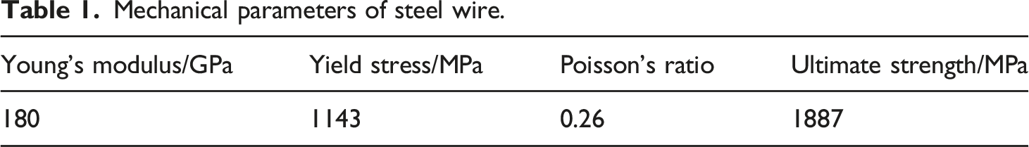
Prior to establishing the PSP finite element model, the stress-strain relationship of the constituent materials should be obtained. The uniaxial curve of steel wire was shown in Figure 1, and the mechanical properties of steel wire could be considered independent of strain rate in this research. The mechanical parameters of steel wire were listed in Table 1. Typical uniaxial tensile curve of steel wire. Mechanical parameters of steel wire.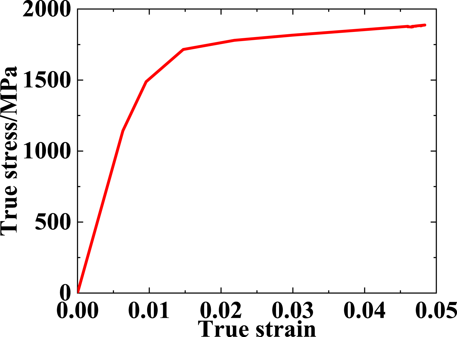
Hot-melt adhesive and HDPE were considered as typical polymers. The type of hot-melt adhesive used was maleic anhydride grafted polyethylene produced by Shanghai Bangzhong Polymer Materials Co., Ltd. Its melt flow rate is within the range of 0.4 to 1.2 g/(10 min), with its elongation at break of 600%, and Vicat softening point of 102°C. As the hot-melt adhesive was a kind of modified HDPE, and its mechanical property was assumed to be similar to that of HDPE. HDPE was treated as a strain rate-dependent material. The stress-strain relationship was represented by a hyperbolic constitutive model proposed by Suleiman et al, 23 which was validated by an earlier publication 24 to describe the tensile mechanical behavior of PE100 material at strain rates ranging from 10−5/s to 5×10⁻²/s.
The hyperbolic constitutive model could be expressed as
As for different strain rate, the coefficients a and b will be different. Therefore, these coefficients can be determined through curve fitting and groups of uniaxial tensile tests under different strain rates.
In order to determine the coefficients, according to the testing standard ISO 527-1 Plastics-Determination of tensile properties,
25
uniaxial tensile tests of HDPE specimens were conducted via LD24.304 test equipment, as shown in Figure 2. The testing machine accuracy grade is 0.5. With the help of the extensometer, the uniaxial tensile tests could be strain-rate controlled. The available vertically moving speed of the loading component ranged from 0.001 to 500 mm/min, and the gauge length of the specimen was only 50 mm, so the test equipment could realize the expected strain rate range, which ranged from 5×10⁻⁵/s to 10−2/s. Electronic universal testing equipment.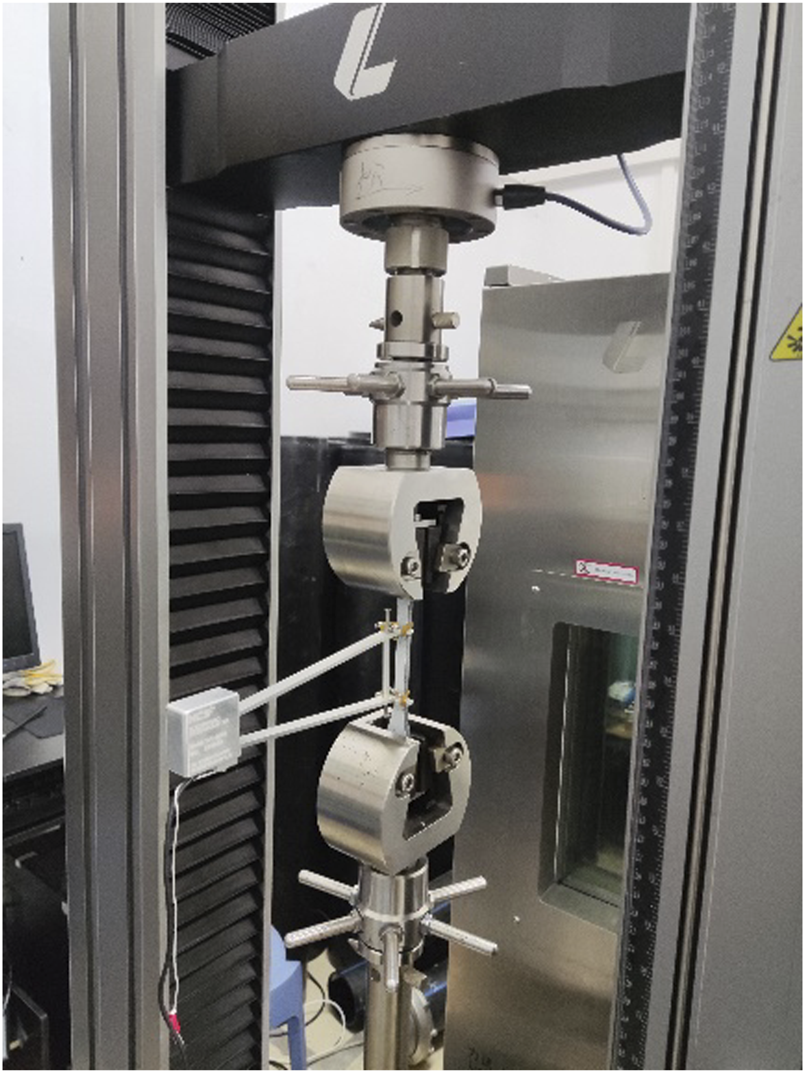
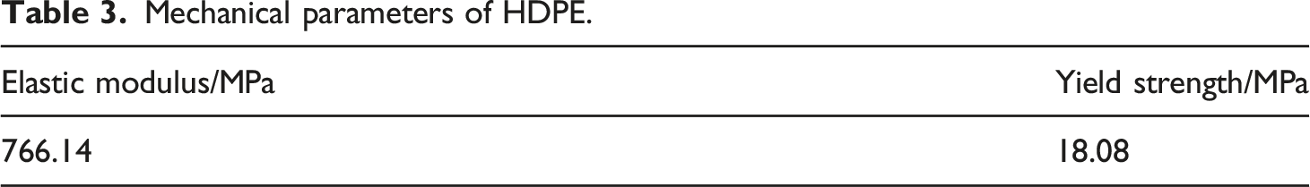
Five specific strain rates were selected, including 10−2/s, 5×10⁻³/s, 10−3/s, 10−4/s, and 5×10⁻⁵/s, and at least three valid tensile curves were acquired for each strain rate. The typical uniaxial tensile curves were shown in Figure 3. It can be found that the slope of curve decreased with the descending strain rates. Curve fitting was carried out using equation (1) to determine the coefficients a and b. With three specimens corresponding to each strain rate, three groups of coefficients a, b could be acquired under each strain rate. Then the average value of a and b could be determined, and these coefficients are listed in Table 2. It could be found that the hyperbolic constitutive model expressed as equation (1) fit the experimental data quite well according to the correlation coefficients R2 very close to 1. Typical uniaxial tensile curves of HDPE under different strain rates. Coefficients of HDPE stress-strain relationship derived from uniaxial tensile tests.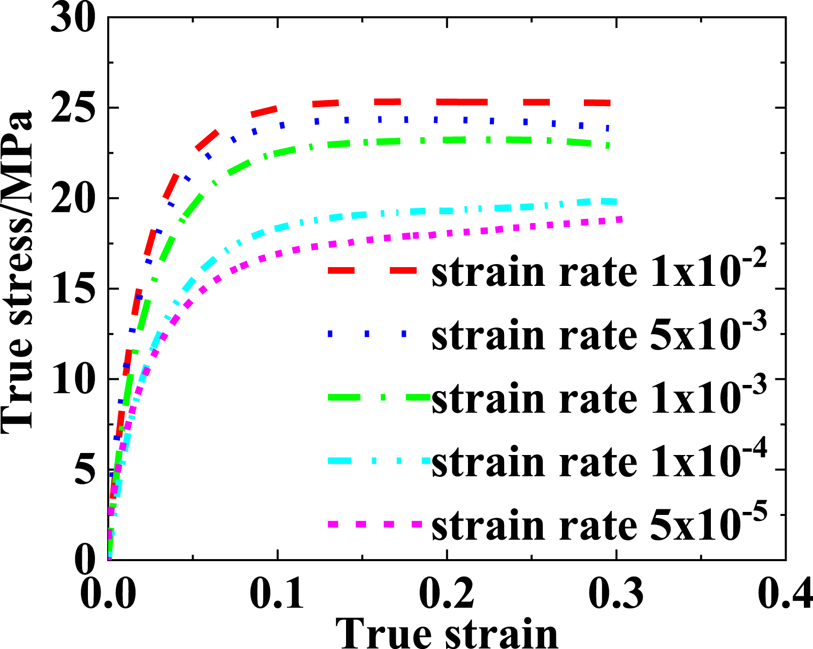
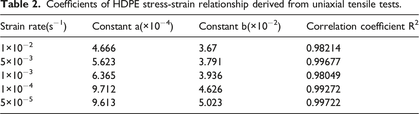
In Figure 4, the derived values of coefficient a from experiments were represented by red circle points, and the derived values of coefficient b were represented by blue circle points. As it was shown in Figure 4, coefficients a and b almost decreased linearly with the increasing strain rate in logarithmic coordinates. In order to obtain the coefficients a, b at other different strain rates, linear fitting was conducted and then coefficients at any strain rate could be determined via the fitting equations. The red solid line signified the linear fitting of coefficient a, and its vertical coordinates were on the left-hand axis. The blue dash line signified the coefficient b, and its vertical coordinates were on the right-hand axis. The fitting equation of coefficient a and b are expressed as equations (2) and (3) Curve fitting of coefficients a, b under different strain rates.

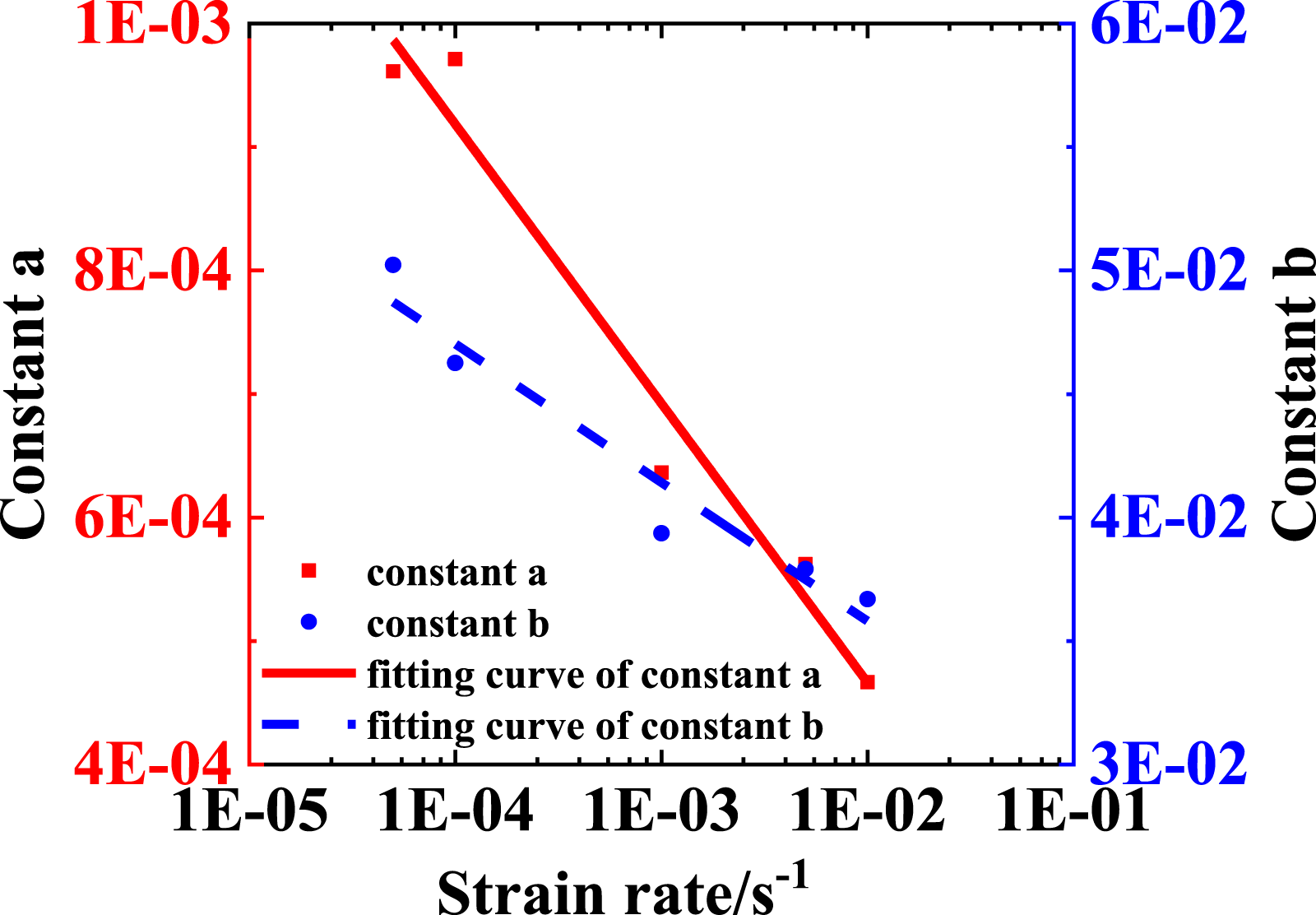
The R-Square of fitting equation of coefficient a was 0.98638, and the R-Square of coefficient b was 0.96702. These indicated that the lines fit quite well.
Referring to previous studies,13,14,25 the foundation settlement usually occurred slowly, and it was reasonable to consider that the strain rate of pipe subject to foundation settlement was 10−5/s. Therefore, in the numerical simulation, it was necessary to get the stress-strain relationship of constituents under a strain rate of 10−5/s. As mentioned before, the steel wires were independent of the strain rate, while the HDPE was not the same.
Owing to the trends of coefficients a, b in Figure 4, coefficients corresponding to 10−5/s could be determined, and the expression could be written as,
As shown in Figure 5, a stress-strain curve represented by expression (4) was depicted, The stress-strain relationship of HDPE under strain rate of 10−5/s.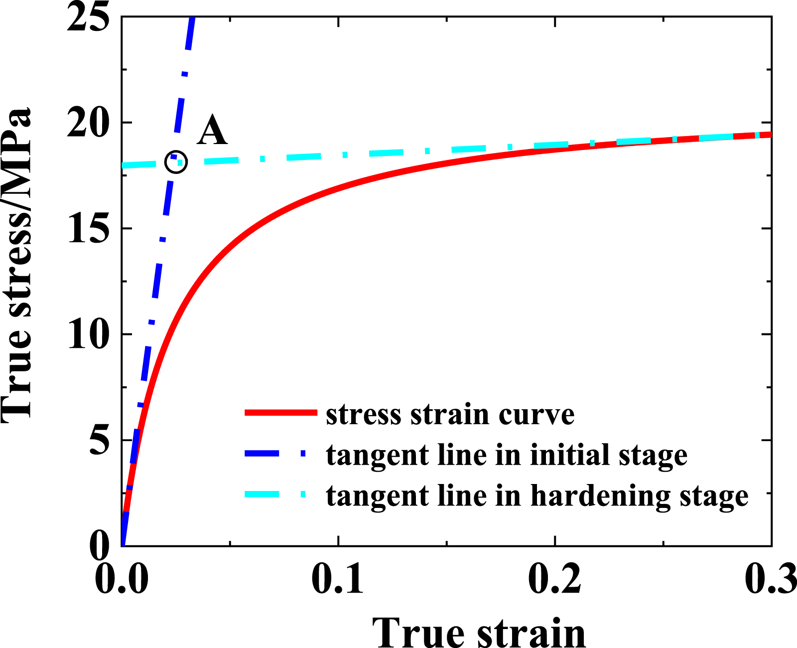
As it was shown in Figures 3 and 5, at low strain rate the yield point remained indistinguishable. Thus, the elastic modulus of HDPE were determined according to the standard ISO 527-1-2019. 26 The slope of the stress-strain curve in the interval between the two strains 0.05% and 0.25% was considered as the elastic modulus.
Mechanical parameters of HDPE.
Finite element modeling
In order to reproduce the failure process of embedded PSP under foundation settlement, a PSP surrounded by soil was modeled with ABAQUS, and the finite element model of PSP only contained the composite pipe itself, not including the fittings or joints. This study did not consider the coefficient of thermal expansion between materials, and it assumed that there were no prestress between the materials.
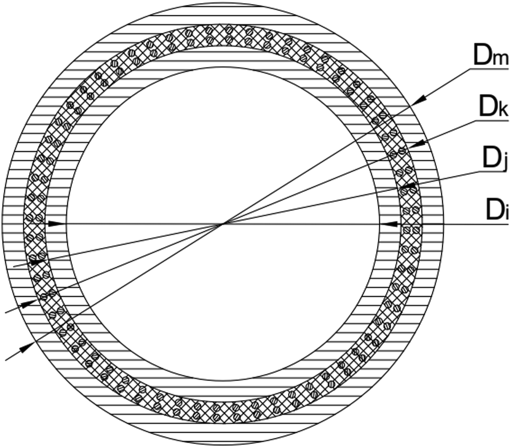
Structural parameters of DN250 PN1.6 PSP and soil model.
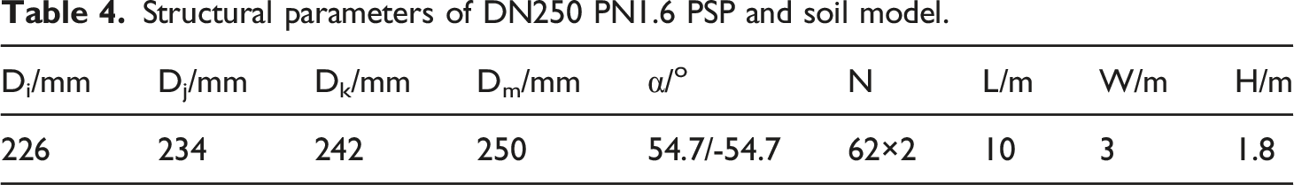
Cross-section of PSP.
The dimension of solid cube was length L = 10m, width W = 3m and height H = 1.8m. The solid cube was divided into three sections, including subsidence area of 5 m, transition area of 1 m, and non-subsidence area of 4 m, as shown in Figures 7 and 8. As the mechanical behavior of PSP and the interaction between pipe and soil were the main concerns, refined mesh could be used in these concerned areas. As for those soil parts distant to PSP, they could be cut into several parts, provided relatively coarse mesh, which could reduce the computation time. All soil parts were meshed with solid elements. The finite element model of PSP embedded in soil. Boundary conditions of the finite element model.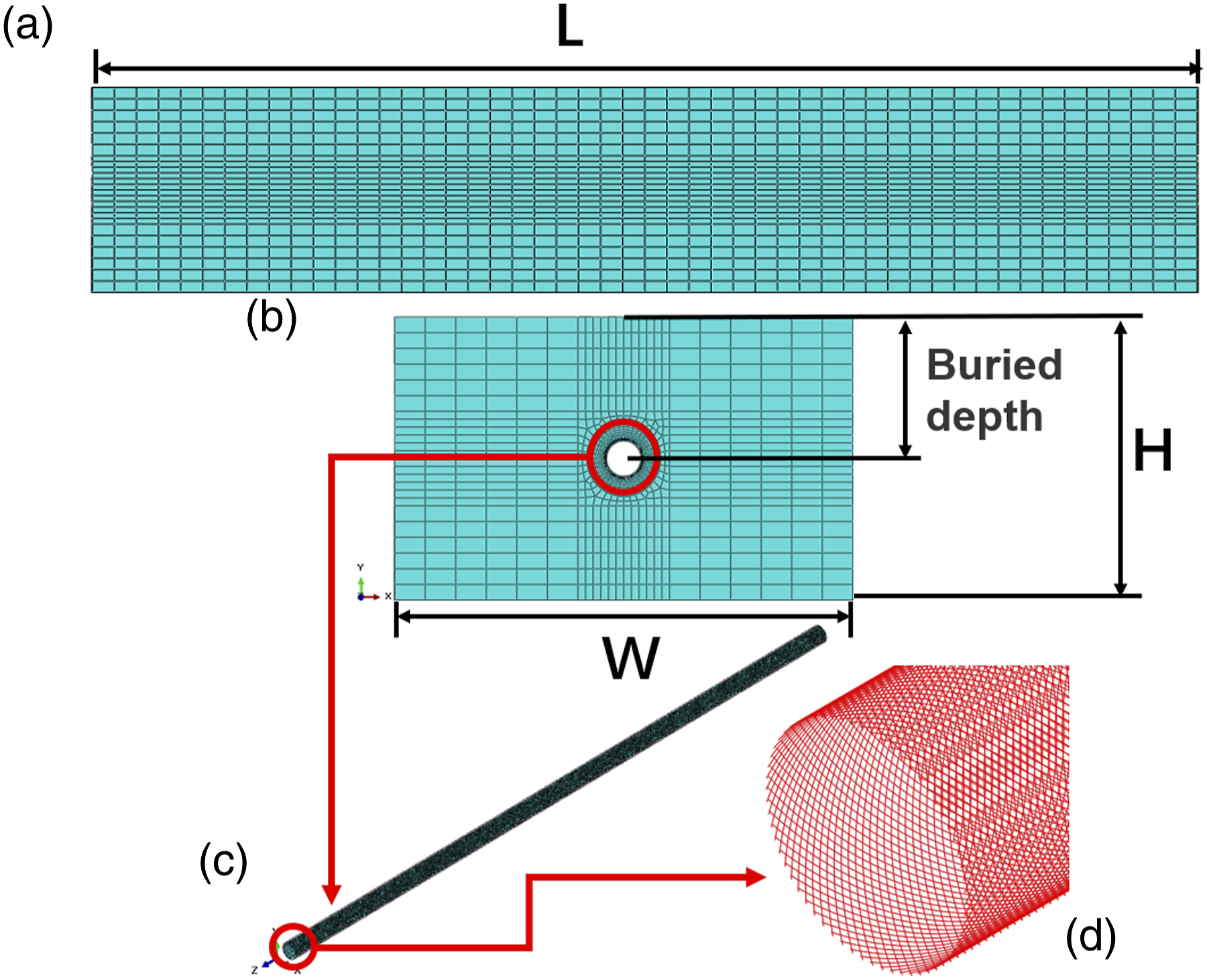
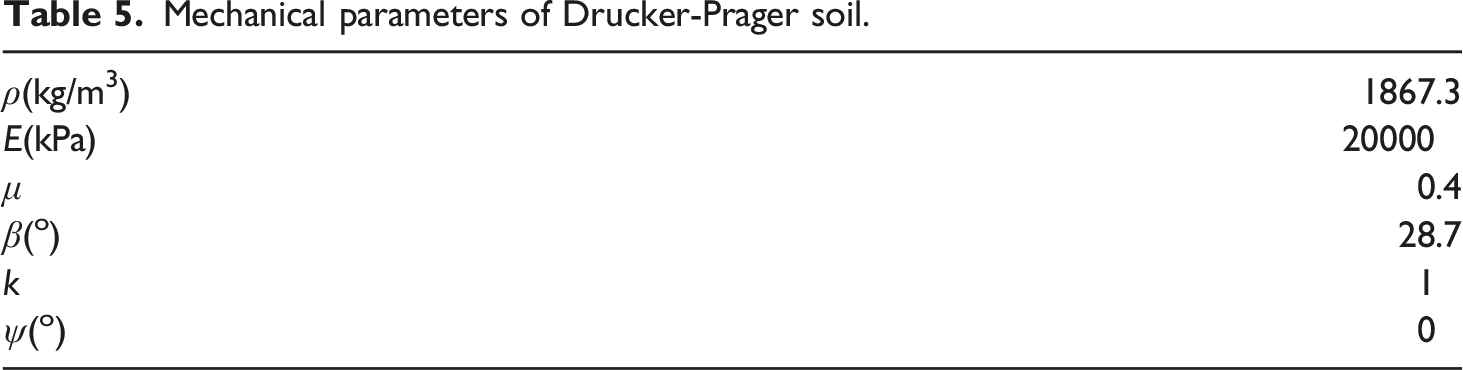
Mechanical parameters of Drucker-Prager soil.
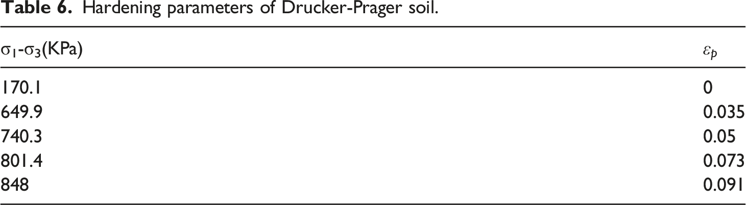
Hardening parameters of Drucker-Prager soil.
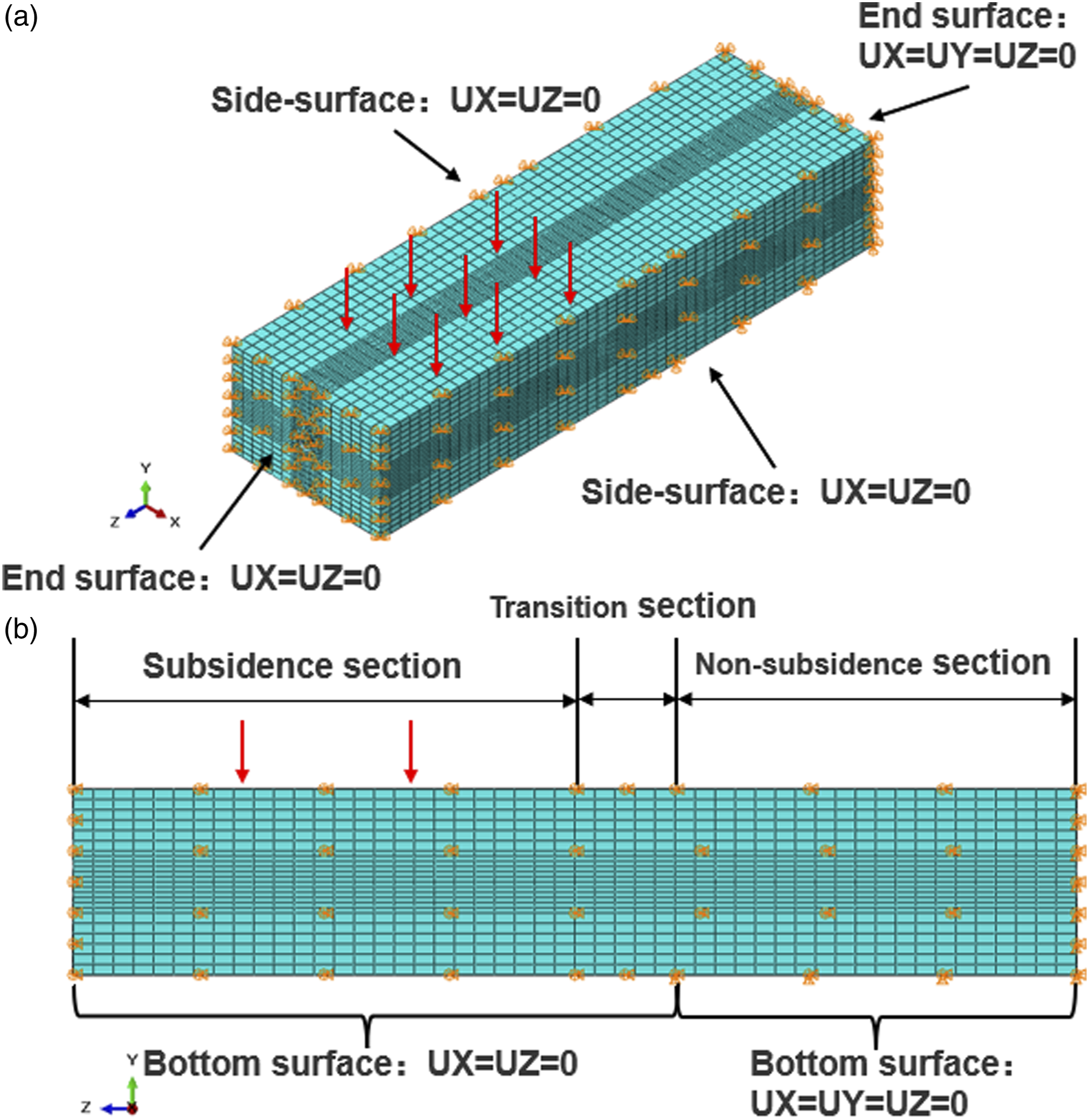
The vertical displacement was applied on the top surface of subsidence area to implement foundation settlement. No displacement was applied on the top surface of the non-subsidence section and the transition section. These two areas were unconstrained. The two side-surfaces of the whole soil cube were constrained in X, Z direction (UX = UZ = 0). The end surface of soil cube near the non-subsidence section was constrained in X, Y, Z direction (UX = UY = UZ = 0), and the other end near the subsidence section was constrained in X, Z direction (UX = UZ = 0). As for the bottom surface, the freedom of each node in X, Y, Z direction on the bottom surface of non-subsidence section were constrained (UX = UY = UZ = 0), and the remaining bottom surface were unconstrained in the Y direction (UX = UZ = 0). The details were shown in Figure 8.
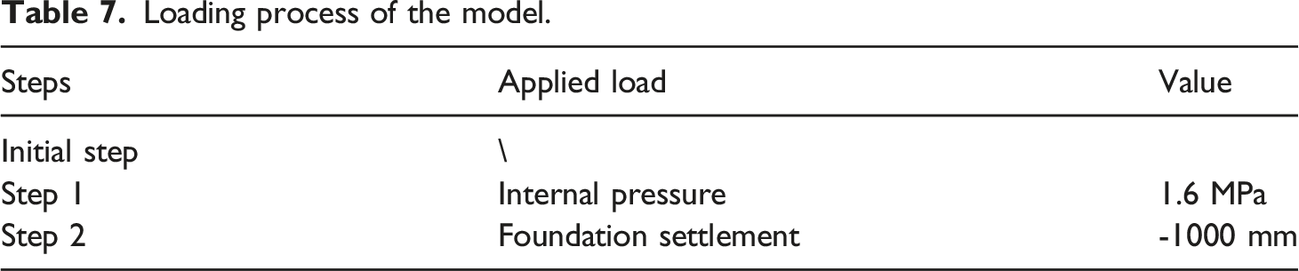
Loading process of the model.
On the aggregate, the element type of this model included C3D8R for HDPE and soil, and T3D2 for steel wires. The element shapes included hexahedral and line shape, with a total of 182,284 elements and 252,322 nodes. The discussion of mesh independence is presented in Figure 9. To strike a balance between time cost and result accuracy, we opted for the “Normal mesh” model. Different mesh densities.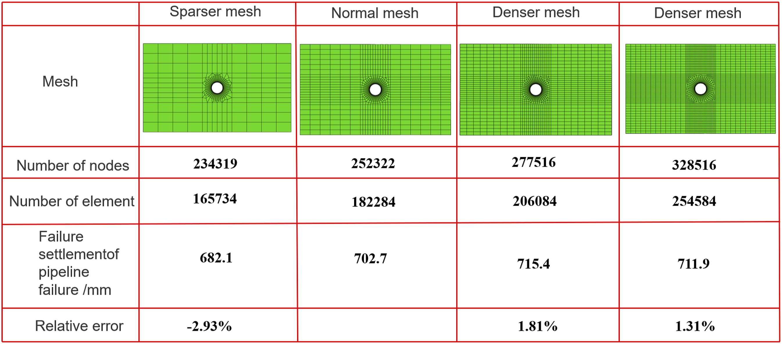
Results and discussion
Structural failure of PSP
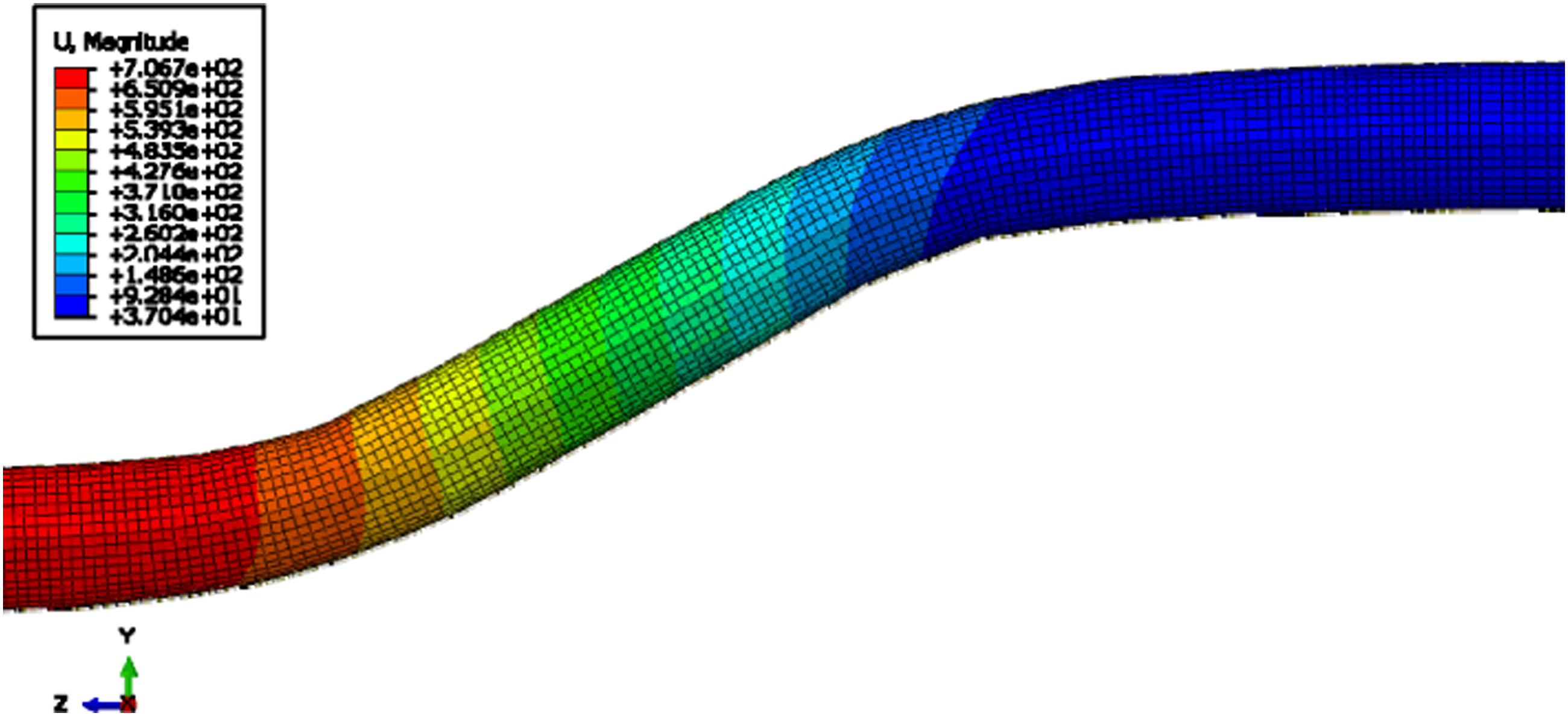
Figure 10 presents the Mises stress distribution of the whole model under foundation settlement of 702.7 mm. Steel wires were the main load-bearing components in PSP, and the maximum stress criterion was employed in this model to check whether the Mises stress of any part of steel wires reached the ultimate strength. Mises stress distribution of steel wires was illustrated in Figure 10, the maximum Mises stress was 1878 MPa, which was exactly the ultimate strength of the steel wires, meaning that failure had occurred. It could be observed that the most critical area was the bottom area of PSP between the subsidence section and transition section, because foundation settlement caused the bottom part of this section convex, while the top part became concave, as shown in zone 1 in Figure 10(c). Being convex indicated the superposition of the tensile stress caused by internal pressure and the tensile stress caused by foundation settlement, while being concave meant that the tensile stress caused by internal pressure was offset by the compressing stress. The superposition and offset of stress corresponded to the red and blue regions respectively, as shown in Figure 10(c). When the vertical displacement applied on the subsidence section increased to 702.7 mm, the failure of PSP occurred, and its deflection along axial direction was demonstrated in Figure 11. Mises stress distribution of steel wires under the foundation settlement (a) the whole model, (b) steel wires mesh, (c) detailed view of steel wires mesh. The deflection of PSP under foundation settlement.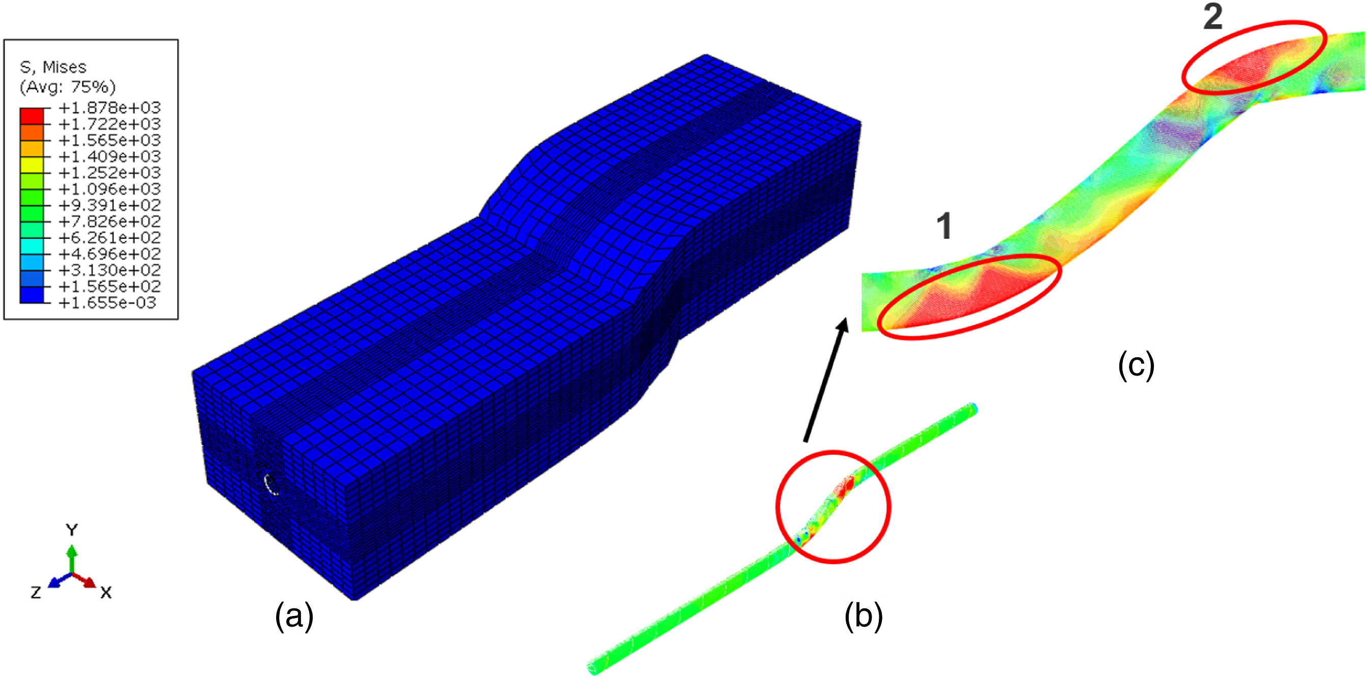
The distribution of equivalent plastic strain of PSP along axial direction could be found in Figure 12. Since the steel wires serve as the main load-bearing components, HDPE would fail when steel wires broke. In the PSP, HDPE only contained a very small amount on load, but once a steel wire failed, all the remaining steel wires would fail instantly. The load of HDPE would rise sharply due to the load transformation from steel wires that occurred, as the steel wires could not undertake load any more. Although the ductility of HDPE was excellent, HDPE would fail immediately in the failure process of PSP because of its low strength. HDPE could not work alone without support of steel wires. As a result, the strain of HDPE was not very large when PSP failed, as shown in Figure 12. The maximum equivalent plastic strain was approximately 19.4%. This indicated that the tensile curve within 30% strain in aforementioned section afforded to represent the mechanical behavior of HDPE in the model. The equivalent plastic strain distribution of PSP along axial direction.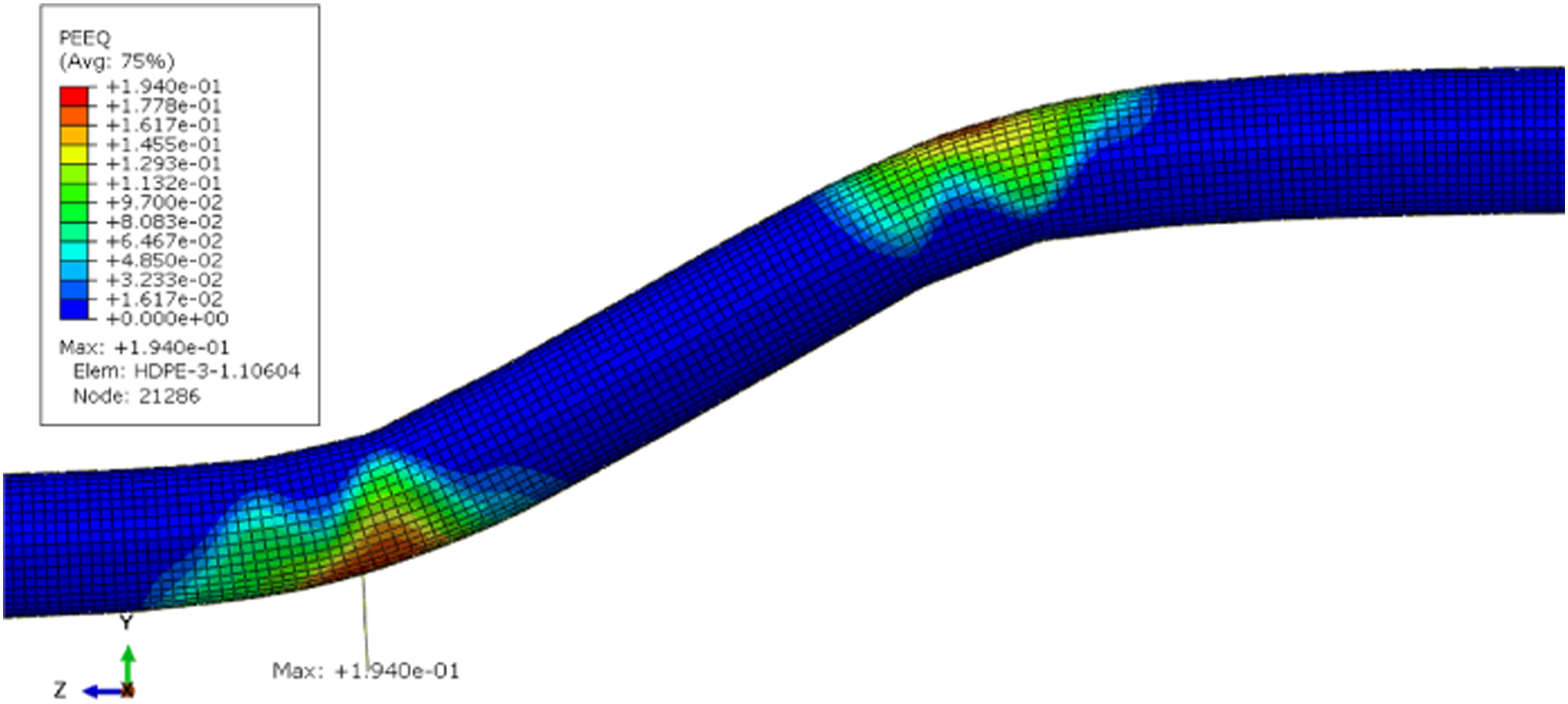
The influence of the foundation settlement on the failure of PSP could be studied by comparing the Mises stress of steel wires in the bending section under different loading conditions. When there was only internal pressure applied to the PSP, the stress was uniformly distributed and equal to 997.9 MPa. Then, adding foundation settlement resulted in the rising of the stress of the bending section up to 1878 MPa, with an increase of 88.20%.
When the foundation settlement reached 606.5 mm, the Mises stress of two steel wires started to reach the ultimate strength. One of the two steel wires was inner steel wire, and the other was outer steel wire. These two steel wires were selected, and the stress distribution were depicted in Figure 13. The stress distribution of two steel wires were similar. The pipe axial coordinate 4000 mm marked the boundary between the non-subsidence section and the transition section, while the pipe axial coordinate 5000 mm marked the boundary between the transition section and the subsidence section. The peaks value of stress appeared at the bottom area between the transition section and the subsidence section, as well as the top area between the non-subsidence section and the transition section, as PSP bended around these two locations. The two peaks correspond to the convex region of the curved part of PSP, and the two valleys between the two peaks respectively correspond to the concave region of the curved part of PSP. The stress distribution of inner and outer steel wires.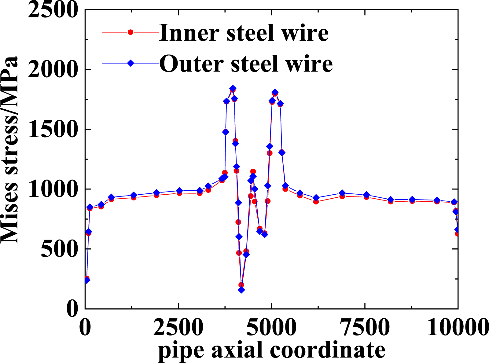
The above results were acquired using the maximum stress criterion of steel wires. But as for many other polymer pipes, yield strength of the matrix was used as the failure criterion. Herein the mechanical performance of the PSP was analyzed with yield strength of HDPE taken as the failure criterion, to discuss the possibility of the failure criterion based on matrix stress for PSP subject to the internal pressure and foundation settlement. Based on the model, the variations of the Von Mises stress of HDPE and steel wires are shown in Figure 14. When the yield stress of HDPE reaches about 18.08MPa, the corresponding settlement displacement is only 193.6 mm and the matrix just starts to undergo plastic deformation. Meanwhile, the Mises stress of steel wires is only 1399MPa which is far from its ultimate strength. Therefore, when HDPE is taken as the failure criterion, the deformation of PSP is very small in the finite element model, and it is hardly to make full use of the excellent mechanical properties of PSP. Mises stress of HDPE and steel wires under foundation settlement.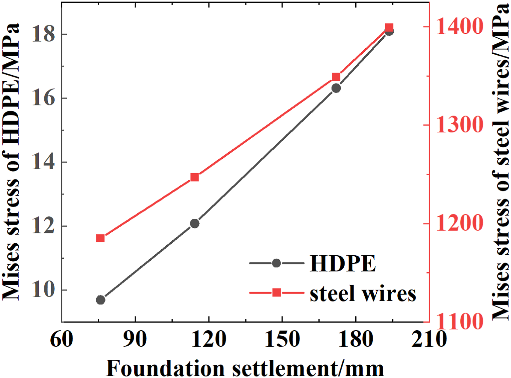
Failure process of the PSP
The increase in foundation settlement changed the position of critical points where the maximum Mises stress of steel wires occurred, and the maximum Mises stress varied accordingly. As shown in Figure 15, the red curve indicated the change of the critical point’s position, the dashed light blue arrows on the left graph represent the boundary coordinates of the transition section. With the increase in foundation settlement, the position of critical point moved from pipe axial coordinate of 4615.7 mm to 3922.98 mm, and then moved to 4953.01 mm. That was a process of successively backward and forward. During the change of the position of critical point, two abrupt changes that were the precipitate drop at foundation settlement of 316.2 mm and sudden rise of 507.2 mm had occurred. As mentioned before, the pipe's axial coordinate at 4000 mm served as the boundary between the non-subsidence section and the transition section, while the pipe's axial coordinate at 5000 mm served as the boundary between the transition section and the subsidence section. Therefore, as the foundation settlement increased, the danger point moves from the transition section to the non-settlement section and then to the settlement section. The green dashed line is a boundary line which indicates two different kinds of danger points’ locations lie on its two sides. As it is in Figure 15, the green dashed line corresponds to the foundation settlement of 316.2 mm. The variation of maximum Mises stress of steel wires under increasing foundation settlement.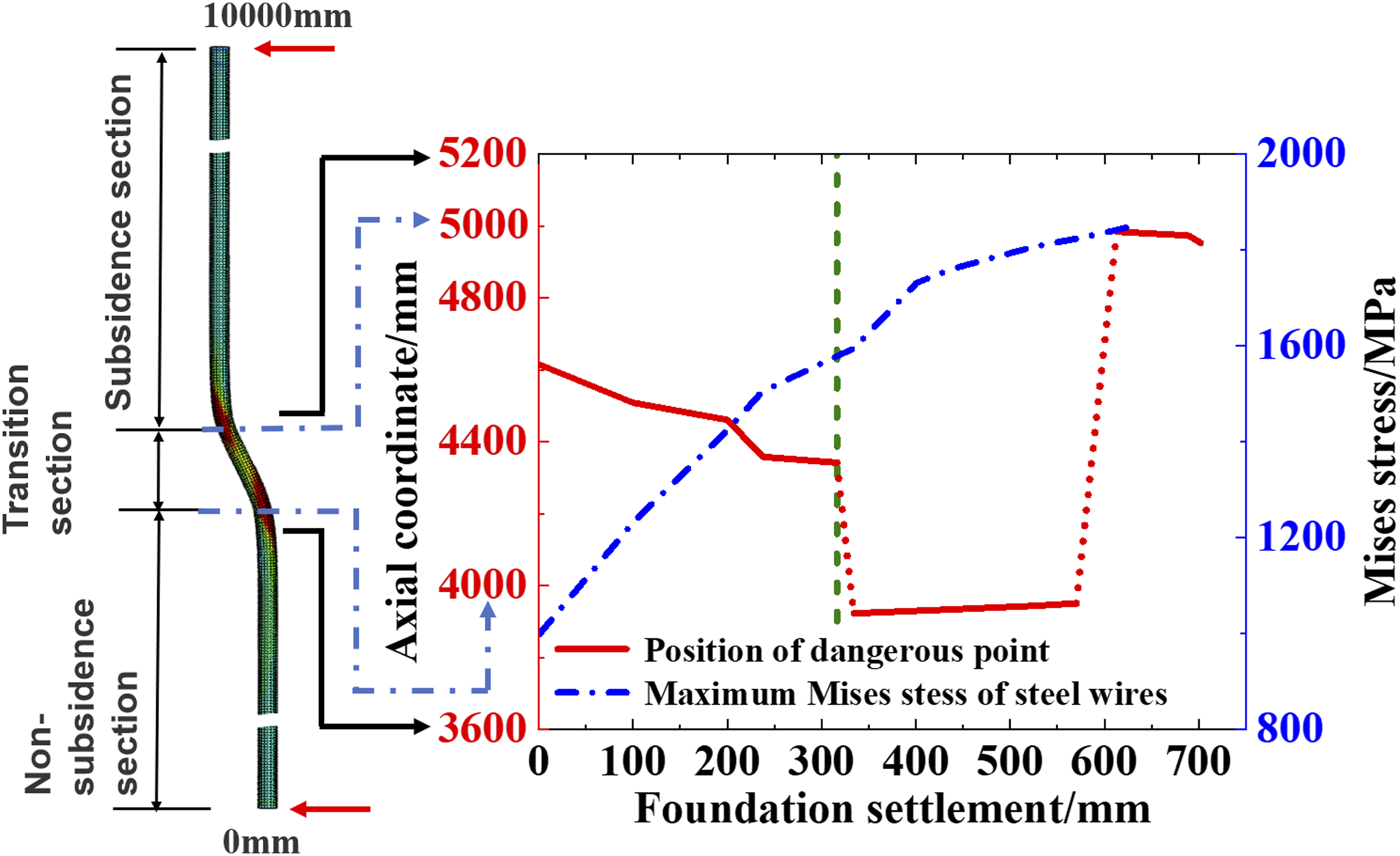
Foundation settlement brought ovality and axial tension to PSP. In the area on the left of the green dashed line, the critical point was at the right sides of the PSP cross-section. During this stage, the foundation settlement was less than 316.2 mm, ovality was dominant to make the Mises stress peak at two sides of the PSP cross-section. When the foundation settlement exceeded 316.2 mm, the critical point was at the bottom and top of the PSP, because the axial tension caused by bending was dominant in the stress-field redistribution. The blue dotted line in Figure 15 depicted the increasing trend of the maximum Mises stress of steel wire with the increasing foundation settlement.
The combination of internal pressure and foundation settlement lead to the failure of PSP, as the internal pressure causes the tensile stress in the PSP, and so does the foundation settlement. Thus, there is competition between these two loading conditions—internal pressure and foundation settlement—on the failure behavior of the PSP. In order to further show the influence of internal pressure on the process of foundation settlement, the relationship of foundation settlement and different internal pressure is studied. As shown in Figure 16, the maximum value of foundation settlement decreases with the increase of internal pressure of the PSP. When the PSP is exerted by lower internal pressure, it can undertake relatively larger foundation settlement. However, when applying greater internal pressure on the PSP, the value of foundation settlement PSP can bear becomes smaller. Relevant data of Figure 16 were fitted. And the fitting formula was shown in Equation (5), whose R2 = 0.9947, and the fitting result was good. The variation of critical foundation settlement with different internal pressures when PSP failure occurring.
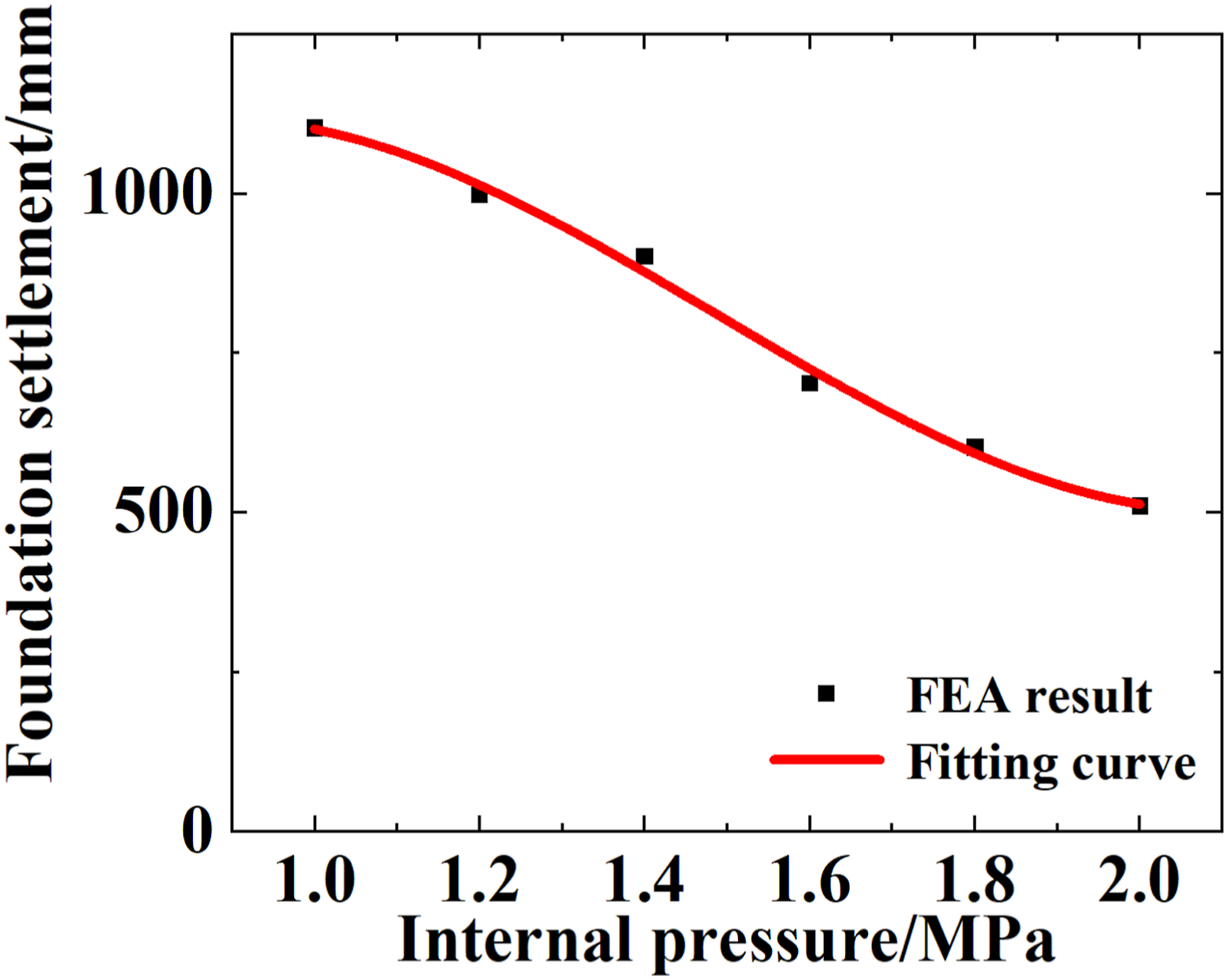
According to equation (5), the allowable foundation settlement value of PSP under the corresponding internal pressure could be predicted. Complicated and time-consuming finite element modeling could be avoided.
Ovality of PSP during failure
In this section, the influence of foundation settlement and internal pressure on pipe’s cross-section is further discussed. A parameter called ovality is defined to describe the extent of cross-section’s deformation. The ovality is defined as Related dimensions of deformation of cross-section of PSP.
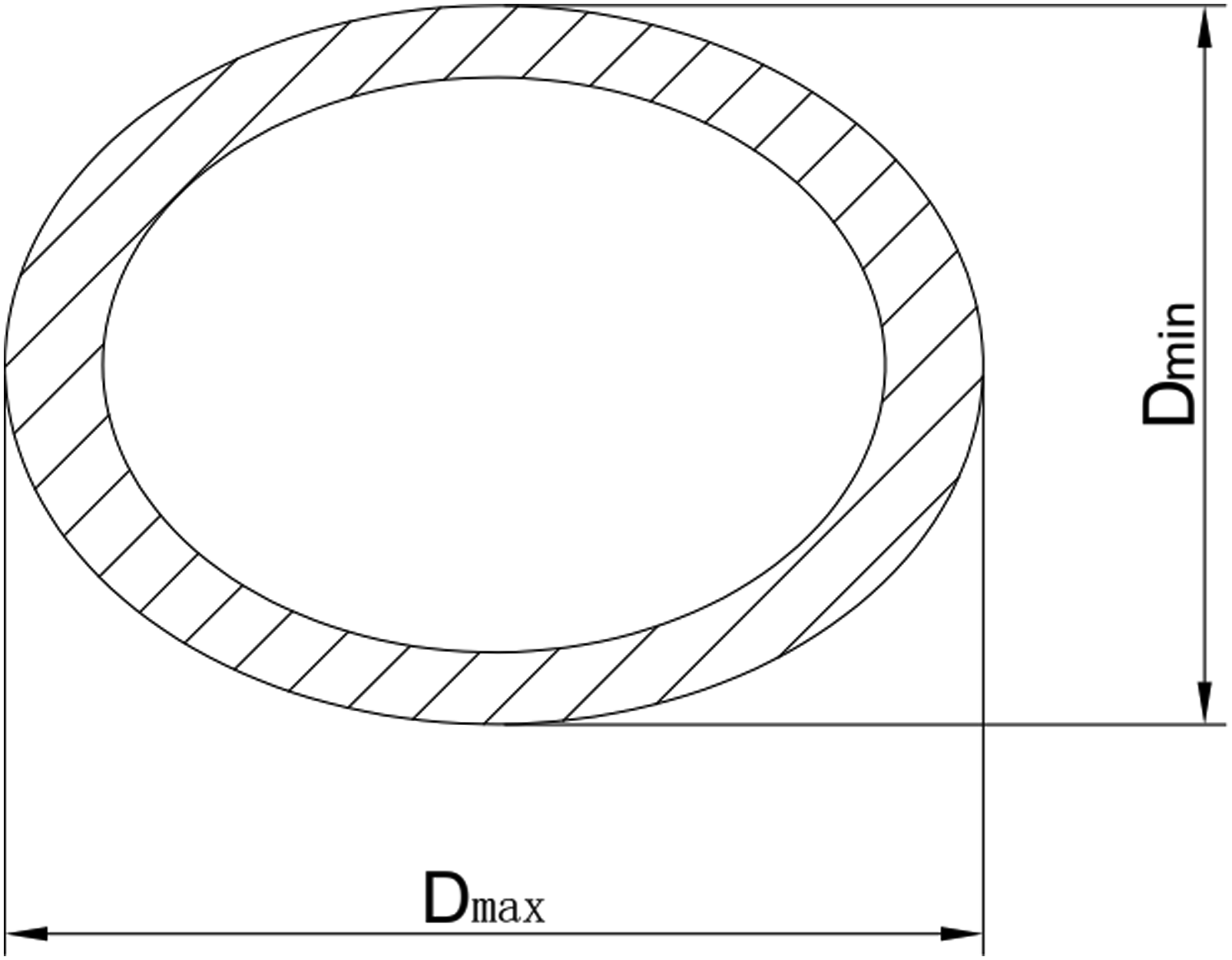
Figure 18 shows the variation of the ovality of PSP containing internal pressure of 1.6 MPa with the settlement displacement. From Figure 18, the ovality of buried PSP keeps rising with the increase in settlement. As the foundation settlement increases, the compression effect of the soil on the pipe grows stronger, leading to a continuous elevation in ovality and more severe stress distribution. This is demonstrated by the three stress contour plots of cross-section of PSP in Figure 18. The red area on the bottom part of the PSP becomes wider and wider. Ovality of the PSP under increasing foundation settlement.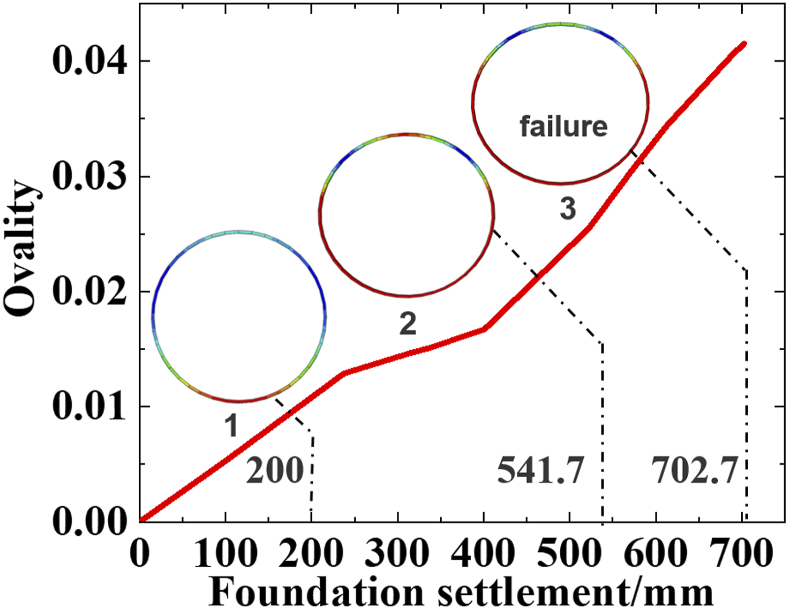
As it is shown in Figure 18, it can be seen that the ovality of buried PSP reaches its peak value of 0.0415 when the pipe fails. The peak ovality is quite small, which confirms that the ovality is not the reason why the PSP fails. It is reasonable that the strength failure of the steel wires is the main cause of the PSP failure.
Moreover, the relationship between the PSP ovality and the internal pressure is investigated. Figure 19 shows that the ovality of the PSP subject to constant foundation settlement of about 500mm is going down with the increase of the internal pressure of PSP. This is because the internal pressure plays an important role in equivalently increasing the stiffness of the PSP. When the internal pressure of the PSP is higher, it is more difficult to make the pipe bend, which is verified by earlier research.
7
Likewise, the PSP is stiffened, and in-plane bending is also difficult to happen on the PSP’s cross-section. The variation of ovality with the internal pressure.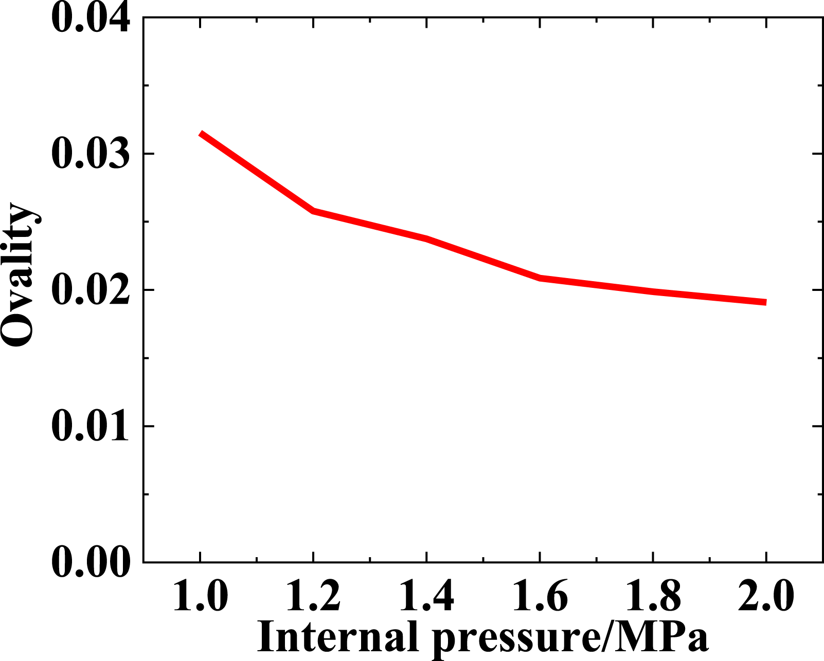
Buried depth
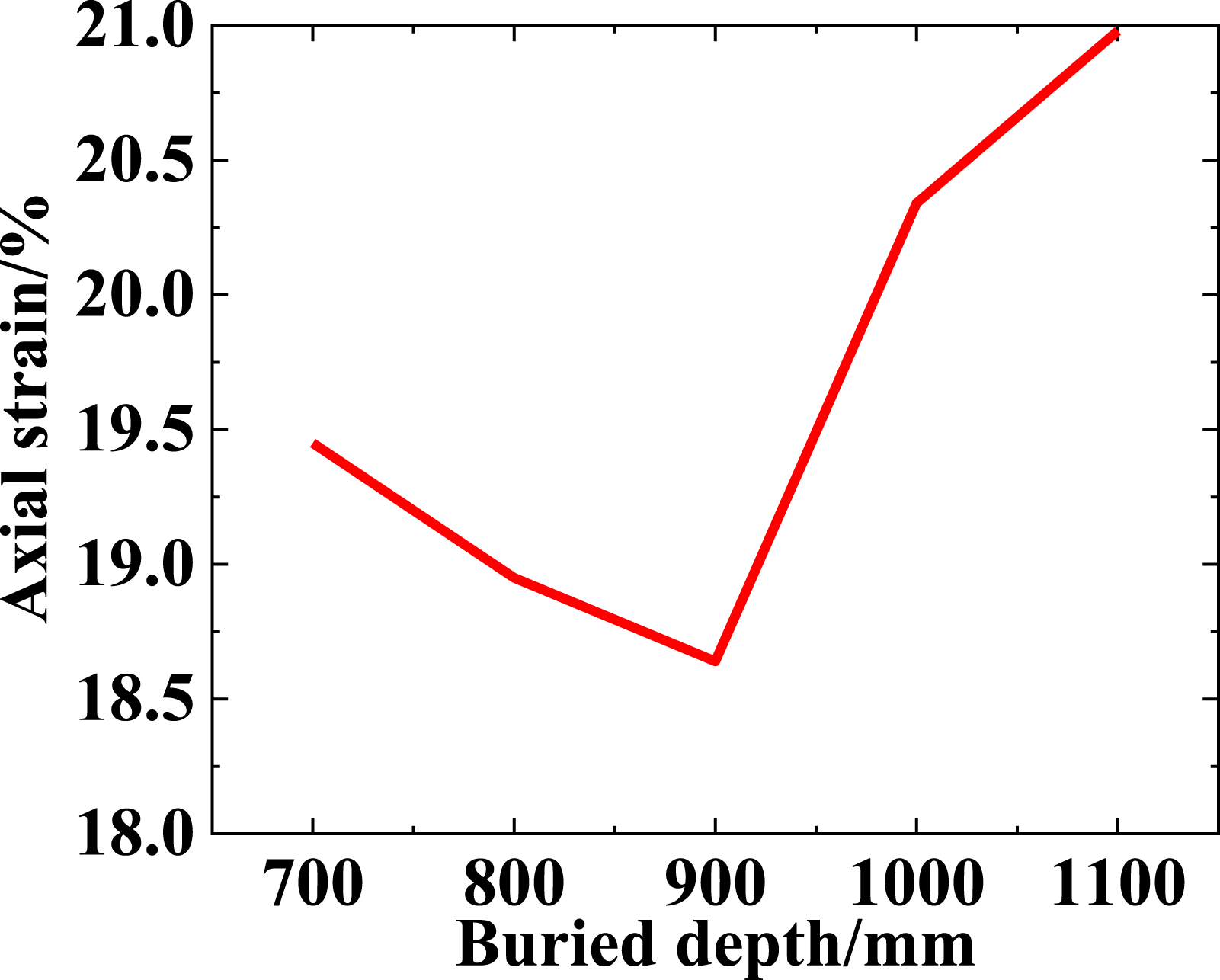
The buried depth in the soil is also an important influencing factor for the mechanical behavior of PSP. The burial depth of the pipeline is shown in Figure 7(b). Figure 20 illustrates the relationship between buried depth of PSP and settlement displacement. From Figure 20, it is observed that when the buried depth of PSP is less than 900 mm, the ultimate bearing capacity of PSP elevates with the increase of buried depth. On the contrary, when the buried depth is greater than 900 mm, the settlement displacement which PSP can bear decreases with the increase of the buried depth. In the model, the total thickness of the soil model is 1800 mm, and a buried depth of 900 mm places the PSP in the middle of the soil. That is to say, when the pipe is located in the upper part of the soil, the settlement displacement is proportional to the buried depth. And the settlement displacement is inversely proportional to the buried depth, when PSP is located in the lower part of soil. When the PSP is buried in the middle, its ability to undertake the foundation settlement is the most outstanding, which indicates the overall stress level of the pipe in that location is the lowest. The axial strain can reflect the stress level to some extent because the foundation settlement mainly causes local bending of the PSP, leading to changes in the axial strain of the PSP accordingly. Thus, the axial strain of the pipe reveals the severity of the deformation subject to the foundation settlement. Based on the finite element model, the relationship between the buried depth of PSP in soil and the axial strain of the outer HDPE layer is illustrated in Figure 21. It can be seen from Figure 21, when the buried depth is less than 900 mm, the buried depth is inversely proportional to the axial strain of HDPE; when the buried depth is greater than 900 mm, the buried depth is proportional to the axial strain of HDPE. It can be deduced that the impact of the foundation settlement on the PSP is minimal when the PSP is buried in the middle. The variation of ultimate bearing capacity of PSP with buried depth. The variation of axial strain with buried depths.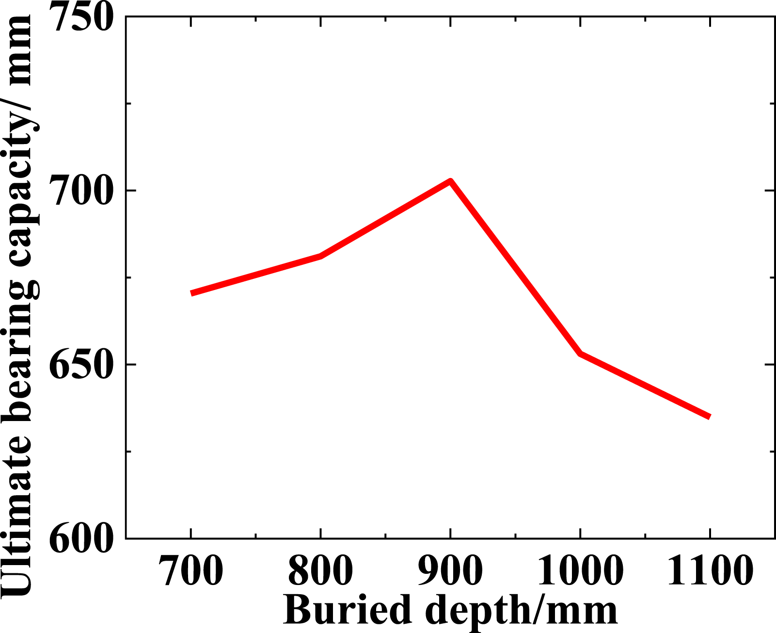
This phenomenon can be explained by the neutral surface of the soil. The failure region of PSP is within the area around the subsidence section and transition section, which is marked by the red dotted ellipse in Figure 22. Consequently, it depends on the stress level of the marked region that whether the PSP subject to combined internal pressure and foundation settlement fails or not. When the PSP is buried in the middle of the soil, the marked region is just on the neutral surface of the soil, as it is shown in Figure 22. The shaded surface is neutral surface and located in the middle of the soil. When the foundation settlement occurs, the soil on upper side of the neutral surface is elongated, and the soil on the underlying side is compressed near the curved part of the soil. Therefore, according to the nature of neutral layer in material mechanics, the strain of longitudinal fiber is proportional to its distance to neutral layer.
33
None of deformation occurs on the neutral surface. As a consequence, the further the actual burial depth of the pipe is from the depth of 900mm, the greater the axial strain of the PSP will be. Therefore, the required settlement displacement to cause PSP failure will be smaller. Diagram of soil settlement.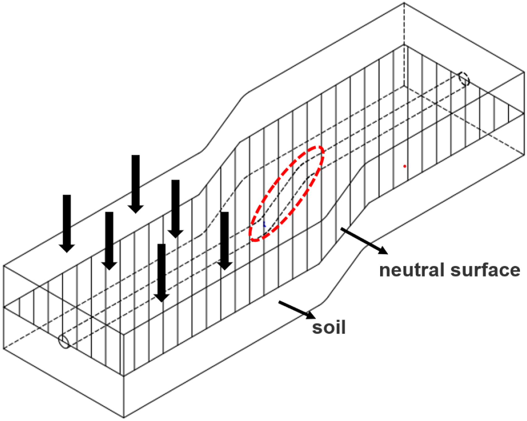
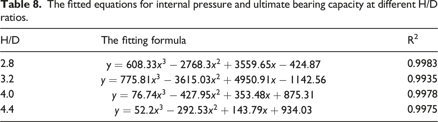
In the standard pipe diameter (250 mm), the influence of different burial depths to pipe diameter (H/D) ratios on the internal pressure and the ultimate bearing capacity of PSP was investigated. From Figure 23, it can be observed that when H/D is 3.6 (burial depth of 900mm), the ultimate bearing capacity of PSP is strongest under various internal pressures. When H/D is less than or greater than 3.6, the ultimate bearing capacity of PSP also weakens as PSP moves away from the neutral axis. The fitted curves of the ultimate bearing capacity for H/D values of 2.8 and 3.2 are close at low internal pressures, but their differences become apparent as the internal pressure increases, which overall aligns with the trends shown in Figure 20. Additionally, it is evident that the influence of different H/D ratios on the ultimate bearing capacity of PSP decreases with increasing internal pressure. The fitting equations for the curves in Figure 23 are presented in Table 8 using a third-order polynomial non-linear fit. The relationship between internal pressure and ultimate bearing capacity under different H/D. The fitted equations for internal pressure and ultimate bearing capacity at different H/D ratios.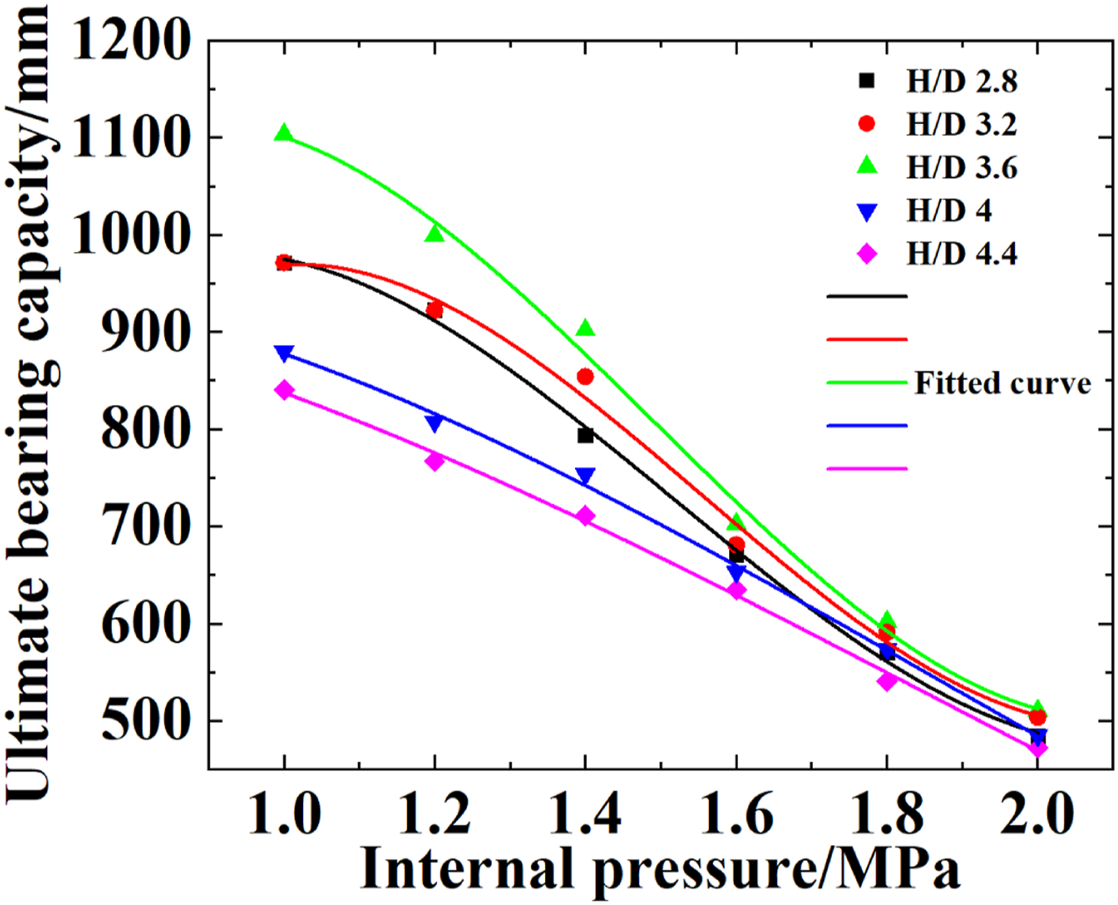
Length of transition section
The length of the transition section is another factor that influences the mechanical behavior of buried PSP in the model. Figure 24 illustrates the variation of the maximum Mises stress of steel wires in PSP with different transition section lengths, under a constant foundation settlement of 800 mm. It should be noted that the maximum Mises stress of the steel wires of PSP decreases with the increasing length of the soil transition section. As a result, it is more difficult for the PSP with a longer transition section to fail. Extending the transition section improves the safety of the PSP subject to the foundation settlement. The reason is that when the transition section is extended, the displacement stagger area of the settlement will be larger, the bending degree of the soil will be alleviated and the maximum Mises stress of steel wires will be reduced accordingly. The variation of the maximum Mises stress of steel wires with different lengths of transition section.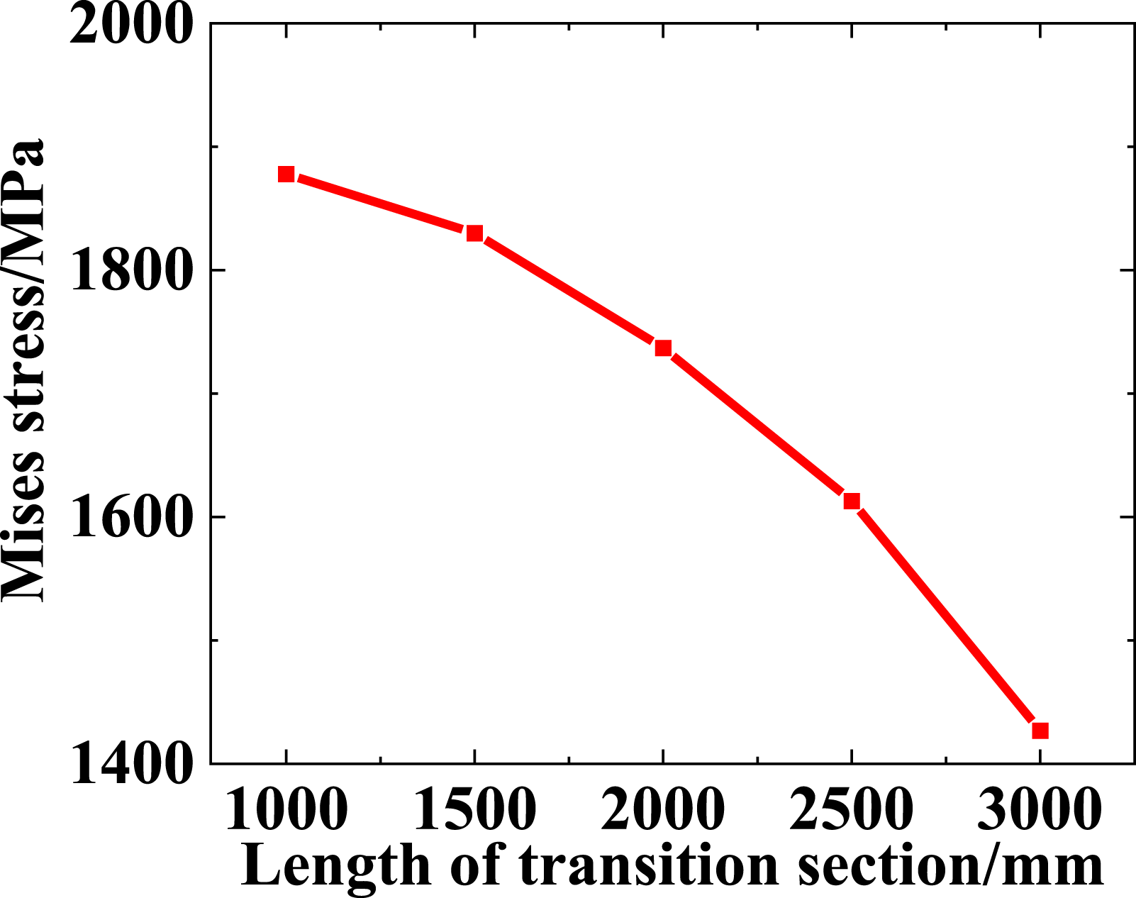
Conclusion
A full-size model of the polyethylene pipe reinforced by winding steel wires (PSP) was established. Steel wires are built to be spiral structure as the real steel-wire mesh of PSP. The nonlinear mechanical behavior of HDPE under different strain rates was taken into consideration. Groups of HDPE uniaxial tensile tests were carried out to acquire the rate-dependent constitutive equation of the HDPE. The stress-strain relationship of HDPE under strain rate of 10−5/s was deduced through the obtained constitutive equation. Subsequently, the mechanical parameters of steel wires and HDPE were incorporated into the model to simulate the failure behavior of PSP embedded in soil subject to combined the internal pressure and the foundation settlement. When there was only internal pressure applied in the pipe, the stress distribution was uniform. After applying the foundation settlement, the stress-field started to redistribute, as the foundation settlement brought ovality and axial tension to the PSP. The failure process of the PSP was analyzed. For the foundation settlement was less than 316.2 mm, ovality dominated, leading to stress concentration at two sides of the PSP cross-section. When the foundation settlement exceeded 316.2mm, the critical point shifted to the bottom of the PSP, as the axial tension caused by bending became dominant in altering stress distribution. The maximum stress criterion of the steel wires was confirmed while discussing the possibility of the HDPE yielding failure criterion. Further, the influence of loading, different structural parameters of PSP and soil were also discussed. (1) It is found that a competition exists between the effects of the internal pressure and foundation settlement on PSP failure behavior. The internal pressure can stiffen the PSP, makeing it more difficult for the in-plane bending occur on the cross-section of the PSP. Therefore, the internal pressure can prevent severe ovalization. (2) The impact of the foundation settlement on the PSP is minimal when the PSP is buried at the midpoint and coincides with the neutral surface. When the PSP is buried farther from the neutral surface, the axial strain of the PSP induced by the foundation settlement increases, and the settlement displacement required for PSP failure decreases. (3) For transition section of different lengths, the maximum Mises of PSP decreases with the increased length of transition section. Extending the transition section can improve safety of the PSP subject to the foundation settlement, because it relieves the bending degree of the soil and reduces the maximum Mises stress of steel wires accordingly.
Future work may include the following aspects: 1. Investigating the impact of truck traffic on the pipe-soil model, which may require relevant field investigations. 2. Validating the resistance factor of compressive strain in the longitudinal or hoop direction through field tests and simulation calculations. 3. Studying the influence of soil quality and H/D on settlement, which will be further explored in future pipe-soil experiments. 4. The long-term creep response needs to be studied in the subsequent buried pipeline research.
Footnotes
Declaration of conflicting interests
The author(s) declared no potential conflicts of interest with respect to the research, authorship, and/or publication of this article.
Funding
The author(s) disclosed receipt of the following financial support for the research, authorship, and/or publication of this article: This work was funded by the National Natural Science Foundation of China (Grant No.51805378), the Foundation of Wuhan Science and Technology Bureau (Grant No. 2019010701011417), the Open Research Fund Program of Hubei Provincial Key Laboratory of Chemical Equipment Intensification and Intrinsic Safety (Grant No. 2017KA01, 2018KA02, 2021KA05), the research fund of Wuhan Institute of Technology (Grant No. K201710), and the Graduate Innovative Fund of Wuhan Institute of Technology (Grant No.CX2022093).
Correction (November 2023):
The Funding section of the article has been updated since its original publication.