
Abstract
Lowering processing temperature of poly(ethylene terephthalate) waste (rPET) and ultra-high molecular weight polyethylene (UHMWPE) by blending to avoid decomposition of rice husk fiber (RHF) during the manufacturing of wood plastic composite (WPC) was one of the main goals of the research study. (rPET/LDPE)-g-MA and (HDPE/LDPE/UHMWPE)-g-MA blends were prepared with good flowability at 240°C. The MA grafted chain in the blends were verified by FTIR. Good miscibility and compatibility of the blends were revealed by SEM. The effect of blends ratios employed as blended matrices on performance properties of the manufactured WPC were explored. MFI and HDT were increased with decreasing (rPET/LDPE)-g-MA ratio. The reversed domain phase between rPET and blended PE mixture was pronounced at 50:50 ratio. Mechanical performances were generally reduced upon decreasing the (rPET/LDPE)-g-MA ratios. The reduction of high strength rPET fraction in the blended matrices was taken as the main cause. Exceeding the reversed phase ratio, the declining of the toughness was retarded due to rising on the interfacial strength and UHMWPE toughener fraction. The effect of DCP/VTMS crosslinker on the properties of the macro crosslinked WPC (XWPC) was investigated. The elastomeric bridges on the sauna cured WPC samples were revealed by SEM. High crosslink density upon increasing the crosslinker fraction had an obvious effect on MFI, HDT, toughness and ductility of the macro crosslinked XWPC. However, the flexible characteristic of the elastomeric amorphous PE chains in the blended matrices at high DCP/VTMS usage was manifested as brittleness retardant for the macro crosslinked XWPC.
Keywords
Introduction
Typically, wood plastic composites (WPCs) are materials manufactured from thermoplastics reinforced with natural fibers. They are used as a substitute or alternative for natural woods, the usage of which are widely prohibited or legally controlled by many countries. Building and decorative materials, such as the extruded outdoor decks, floors, windows, and doors, are among their main applications. Polyolefins, such as poly(vinyl chloride) (PVC), poly(propylene) (PP), and poly(ethylene) (PE), are commonly used as matrices. There are advantages and disadvantages to these matrices. For example, PP is easy to process with high service temperature product, but it has a low ultraviolet radiation (UV) resistance. The PEs offer decent melt processing, but it has a low service temperature. The PVC has an outstanding in environmental deterioration resistance, but it is harmful during melt extrusion processing and special treated processors are normally required. There has been much research into the works and attempts to overcome those weaknesses.
There were several reports on PP/wood flour WPC made with various wood flour particle sizes. It was found that the mechanical properties of wood composites depend on the fiber aspect ratio. 1 Polymer blends employed as matrices have been extensively studied and phenomenally succeed in improving the properties of WPCs such as impact strength, tensile strength, environmental stress cracking, low temperature impact properties, and more.2–6 Environmentally friendly materials and the circular economy are the current megatrends for industrial product marketing including interior and exterior construction materials. The driving force from these industrial interests, the utilization of polymeric waste from the consumer product such as PP, PET and PE, and cellulosic fibers from agro-industry by-product for manufacturing of WPC have gained their attentions by both researchers and industries especially for the bio-circular green economic (BCG) policy. 7 The WPCs made from recycled polypropylene (rPP) and wood flour were produced by extrusion. 8 It was found that the mechanical and durability properties were improved by using fine wood fiber. Using recycled high-density PE (rHDPE) and fibers from rice crop, and recycled polystyrene (PS) foam reinforced with durian husk fiber (DHF) waste for producing WPC were explored.9,10 It was demonstrated that fiber from rice straw showed the best candidate as reinforcement.
Furthermore, the effect of fibers type on the mechanical properties of WPCs were published.11–13 Improving their long-term properties by grafting, crosslinking and matrix blending, fiber modification, and adding high performance fillers were among the typical methods studied in previous literatures.14–16 Silane grafting followed by a water crosslink reaction (or sauna treatment) of the polymer matrix to form a loosely macro crosslinked chain, especially on PP and PE chains, has received much attention from industrial applications and fundamental research. 17 The macro crosslinked provides obvious advantages, such as easier to process than the completely tight crosslinked thermoset, low capital investment, and favorable properties in the processed materials.18,19 Vinyl silane was chemically grafted onto polymer chain via free radical reaction using peroxide as an initiator. Then, it was hydrolyzed and condensed to create siloxane bonds (–Si–O–Si–) between the chains and/or bond between cellulosic fiber and polymer. The macro crosslinked, via silane bridges, results in outstanding performance properties.
Generally, the fracture toughness and impact resistance of WPCs are also among the most important properties for different bending loaded applications. To achieve the highest load bearings possible, various modifications such as toughening of the matrix with stiffer polymer, rubber toughener, hybridization of the natural fiber with engineering reinforcement, and/or employing the inorganic fillers were studied. 20 Treatment or modification of the fiber/filler was one of the main methods that enhanced the properties of WPCs.21,22
In this publication, manufacturing WPC from Poly(ethylene terephthalate) waste of post-consumer drinking bottle (rPET) reinforced with rice husk fiber (RHF) as green raw materials from agro-industry by-product and toughened with ultra-high molecular weight PE (UHMWPE) was conducted. Construction materials manufactured by extrusion process is one of the main industrial application goals for this research work. rPET and UHMWPE are known as high melt processing temperature polymers. Typically, a melting temperature above 300°C is required for melt flow processing of those polymers. In contrast, the cellulosic RHF is promptly decomposed when temperature exceeds 250°C. Thus, the preliminary research challenge on this work was “processable melt compounding of WPC having rPET, UHMWPE and RHF at the temperature at 250°C or below without the thermal deterioration of RHF.” The polymer blending technique was adopted to reduce the melt processable temperature of rPET and UHMWPE. The maleic anhydride (MA) grafted blends of (HDPE/LDPE/UHMWPE)-g-MA and (rPET/LDPE)-g-MA were prepared and then employed as the blended matrices. The effect of the MA-grafted blends ratios employed as blended matrices on the properties of the manufactured WPC were also investigated. Finally, the study of peroxide/silane crosslink system on the properties of the produced macro crosslinked WPC was conducted.
Experimental
Materials
Summary of the recommended melt processing temperature and HDT of HD7000 F, LD1905 F, UHMWPE (SUNFINE UH900) and PET, respectively.
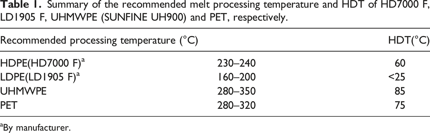
aBy manufacturer.
Rice husk hull from a local rice mill (Nakorn Ratchasima, Thailand) was ground into a fine powder RHF by a hammer mill machine. The RHF was obtained and collected via the sieving machine with the mesh size ranging from 100 to 500 microns. The RHF was vacuum dried at 105°C for 3 h prior melt compounding into WPC.
(HDPE/LDPE/UHMWPE)-g-MA and (rPET/LDPE)-g-MA blends preparation
Blending ingredient and batch size quantity of (a) (HDPE/LDPE/UHMWPE)-g-MA and (b) (rPET/LDPE)-g-MA, respectively.
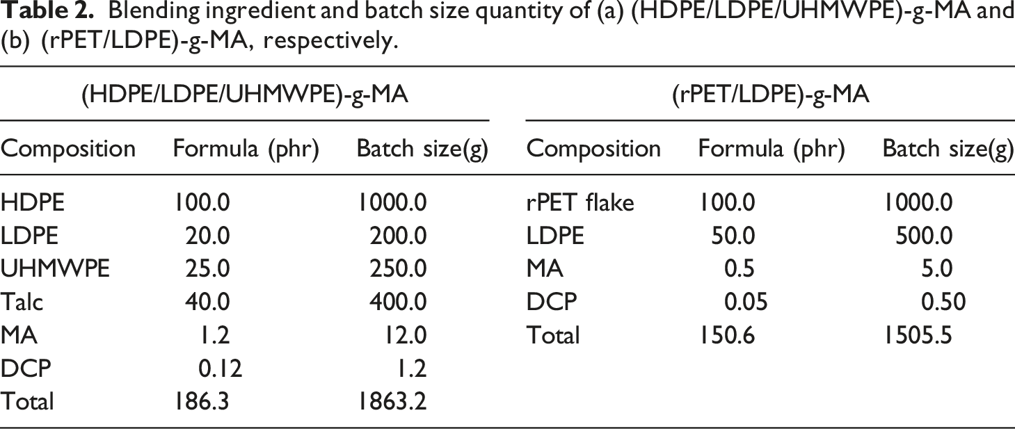
For the (rPET/LDPE)-g-MA blend preparation, a similar melt compounding procedure as described was adopted. rPET flake was vacuum dried at 100°C for 8 h prior to compounding. The calculated batch size quantity comprised of 1000 g of the vacuum dried rPET flake, 500 g of LDPE, 5.0 g of MA pellet, and 0.50 g of DCP were placed in the securely sealed plastic bag. The mixture of ingredients was placed in the oven at 100°C for 2 min. After MA and DCP were completely liquidized, the mixture was immediately transferred into high-speed mixer chamber and vigorously stirred for 2 min. The solid mixture was then undergone melt compounded onto the co-rotation twin screw extruder at the barrel temperature profiles at 230, 240, 250, 270 and 230°C, from the feed to die zones, respectively. The (rPET/LDPE)-g-MA blend resultant strand was air cooled and then pelletized.
WPC manufacturing and test specimen preparation
The WPC compounding was performed using twin screw extruder as schematically shown in Figure 1. Regarding the designed WPC formulation, the solid mixture comprised of (HDPE/LDPE/UHMWPE)-g-MA, (rPET/LDPE)-g-MA, RHF, talc and stabilizer were pre-blended and vacuum dried at 90°C for 3 h. Then, they were vigorously stirred in high-speed mixing chamber. For the crosslink system, DCP/VTMS solution was prepared beforehand and then added onto the solid mixture in the high-speed mixing chamber. The solid ingredients were then constantly fed via single screw feeder into a co-rotation twin screw extruder at the barrel temperature profiles of 220, 225, 230, 240, and 230°C from the feed to die zone, respectively. The melt compounding was achieved at a screw revolution of 25 rpm. The resultant WPC strand was cooled down and pelletized. The WPC pellet was vacuum dried at 90°C for 3 h before undergoing injection molded into the standard test specimens. The injection molding machine, CLF-80T (Chuan Lih Fa Machinery Works Co. Ltd., Tainan, Taiwan), was employed. The barrel temperatures profile of the machine was electrically set at 190, 200, 210 and 220°C from the feed to nozzle zones. The mold temperature was set at 45°C with a cooling time of 25 s. The obtained test specimens were annealed at atmospheric environment for 24 h prior to performing the tests. For the DCP/VTMS macro crosslinked system, half of the injected specimen were undergone sauna incubation in the moisture saturated and tightly closed oven at 90°C for 6 h. After that, the residual moisture was removed by vacuum drying at 90°C for 3 h. Then, they were annealed in an atmospheric environment for at least 24 h before conducting the tests. Schematic diagram for (HDPE/LDPE/UHMWPE)-g-MA and (rPET/LDPE)-g-MA blends compounding, WPC Compounding, and injection molded test specimen preparation, respectively.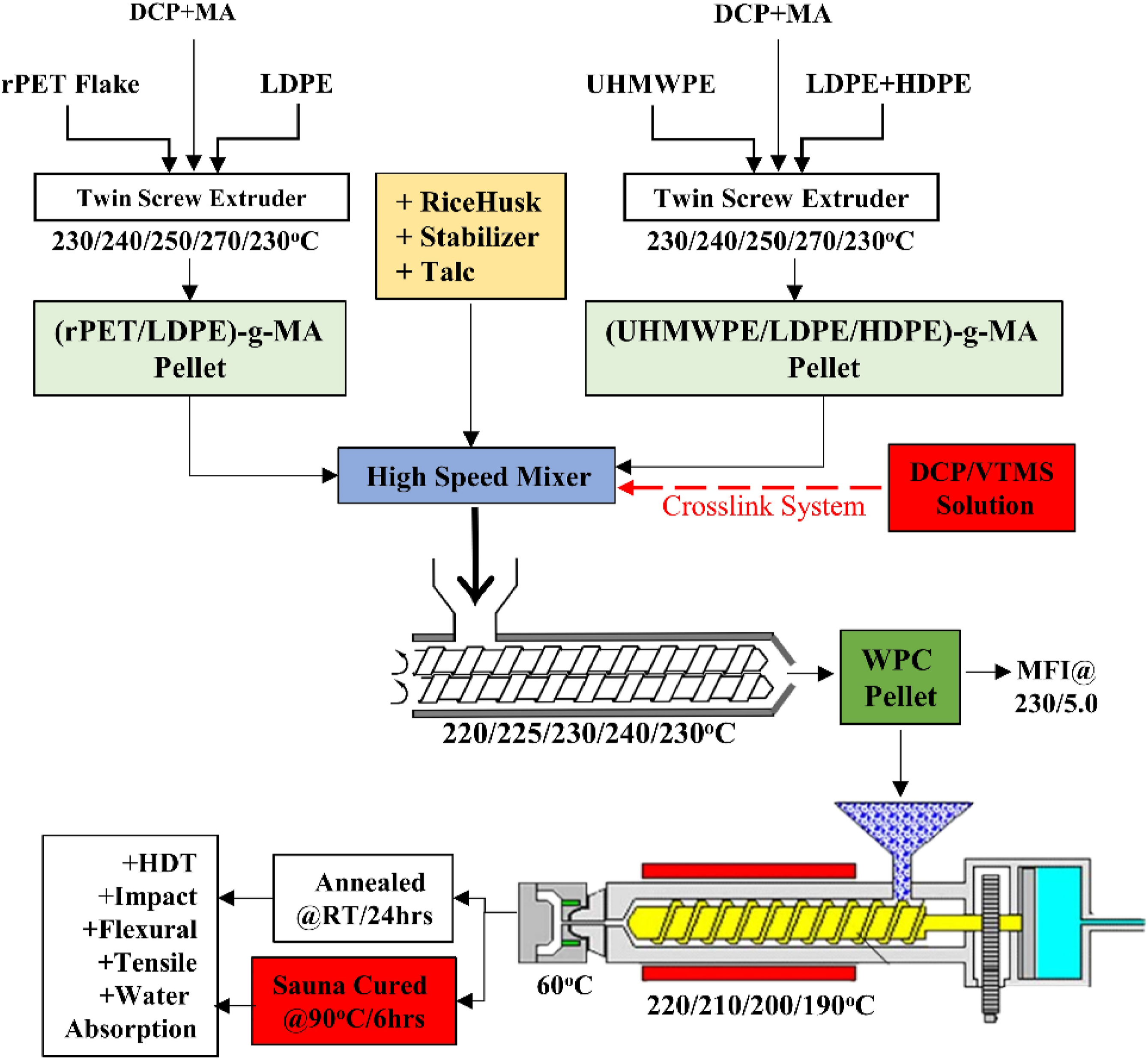
Material characterization and testing
The mechanical properties evaluation by means of three-point flexural bending, tensile, and Izod impact strengths (both notched and unnotched modes) tests were carried out in accordance with ASTM D790-10, ASTM D638 and ASTM D256-10 × 101, respectively. A universal testing machine (Instron Model 5565, Norwood MA, USA) with load cell of 5 kN was employed. The flexural span length at 80 mm and crosshead speed of 15 mm/min were assigned. The injection molded standard test specimen size of 3.2 mm × 12.7 mm × 125 mm was used. For the tensile testing, the strain rate at 50 mm/min by means of the crosshead speed was also electronically controlled. The ASTM Type I dumbbell shape standard specimen made from the above injection molding process was employed. The pendulum impact testing machine (Instron Ceast Model 9050) was employed. The impactors having the striking energy of 2.16 or 11.0 J was installed for notched or unnotched impact strength measurements, respectively. At least five replicate test pieces were conduct for all tests. The averaged and standard deviation values were recorded and reported.
The heat distortion temperature (HDT) was obtained using an Atlas testing machine (HDV1, Atlas Material Testing Technology LLC, Mount Prospect, IL, USA), and ASTM D648-07 was followed with the assigned standard load of 455 kPa and heating rate at 2.0°C/min. The melt flow index (MFI) was performed in accordance with ASTM D1238-13 using a Kayeness melt flow indexer (Dynisco, Inc., Franklin, USA) at 5.0 kg static load. The durability of the RHF wood composite samples by means of % water absorption, % thickness swelling during upon 1- and 7-days prolonged water submersion, were measured in accordance with ASTM D570-98 × 101. Three replicate samples were used for those tests. The averaged and standard deviation values were calculated and reported. The morphological observation by scanning electron microscope (SEM) was conducted at the accelerating voltage of 15 keV (JSM 6400, JEOL Ltd., Tokyo, Japan). The Mettler Toledo TGA/DSC1, Star System (Schwerzenbach, Switzerland) was employed for measuring the decomposition temperature (Td) of RHF. The IR spectra at 1 cm−1 resolution was acquired on the thin film sample. 30 scans were performed. The T27/Hyp2000 FTIR equipped with attenuated total reflection (ATR) sampling technique (Bruker Scientific LLC, MA, USA) was employed.
Results and discussion
Characterization and testing of MA-grafted blends raw materials
The main raw materials for manufacturing WPC in this research work were (HDPE/LDPE/UHMWPE)-g-MA, (rPET/LDPE)-g-MA, RHF reinforcement and talc filler, respectively. All of them, except for talc filler, were in-house prepared. As mentioned earlier, one of the main challenges for this innovative research was the attempting to use as low processable temperature as possible for manufacturing WPC comprised of high melting temperature polymeric matrices without deteriorating low Td RHF. As given in Table 1, the recommended processing temperatures of PET and UHMWPE are normally above 300°C. However, the degradation temperature (Td) of most cellulosic natural fibers is typically below 240°C. In particular in the fiber with high lignin content, a Td below 200°C is commonly reported. Accordingly, the upper limit melt compounding temperature for manufacturing WPC from high melting point polymer matrices reinforced with the natural fiber is restricted by the Td. Thermal decomposition of natural fiber during WPC manufacturing will cause a dramatic mechanical/physical properties deterioration. One of the alternative solutions to overcome this processing burden is by compatible/miscible blending high melting point polymer matrix with low melting point polymer constituent as adopted in this work. By such a method, the flow ability, processability, compatibility, and mechanical properties of the resultant blend and eventually the final WPC product must be justified and satisfied by testing.
Figure 2 shows the TGA thermogram of RHF reinforcement and talc filler employed in this work. It was seen that the Td window of the employed RHF was 200–250°C. Above 250°C, the RHF decomposition process indicated by the weight loss was obviously observed. So, it was confirmed that the allowed upper limit for processing RHF as reinforcement in the WPC manufacturing must not exceed 250°C. For the talc filler, the TGA thermogram revealed no sign of weight loss at temperatures above 400°C. TGA thermogram of ( ) RHF and (- -) talc filler.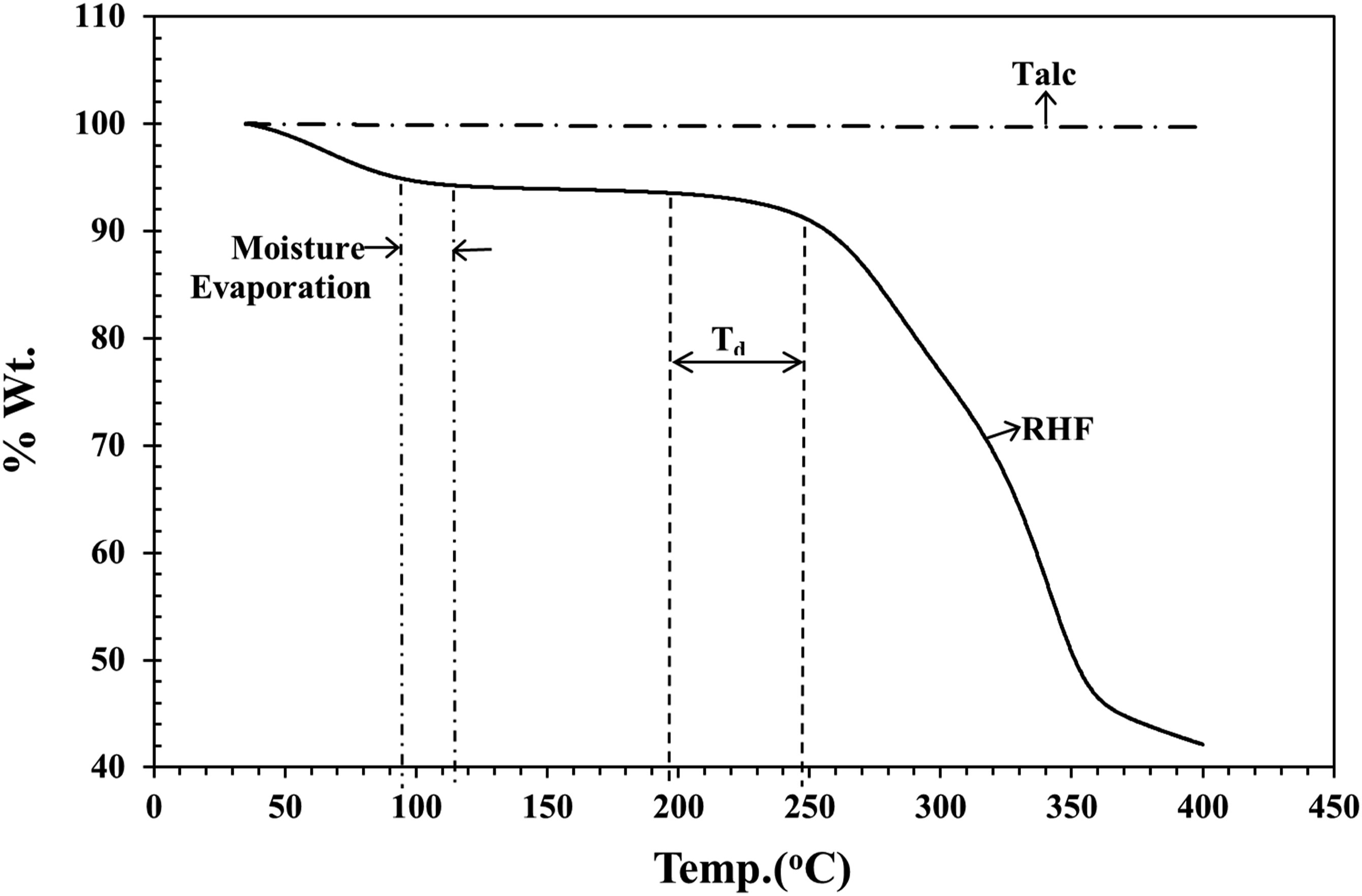
Figure 3 illustrates the SEM photos of the hammer mill grounded RHF and talc filler employed for manufacturing WPC in this work, respectively. SEM photo of RHF reveals that the fiber lengths of the grounded RHF were varied from 145 μm to approx. 500 μm. It was seen that rice hull fiber fraction was the main composition of the grounded RHF. For the talc filler, a very thin flat flake with approx. width of 10 μm was visualized by SEM. SEM Photos of (a) RHF and (b) talc filler.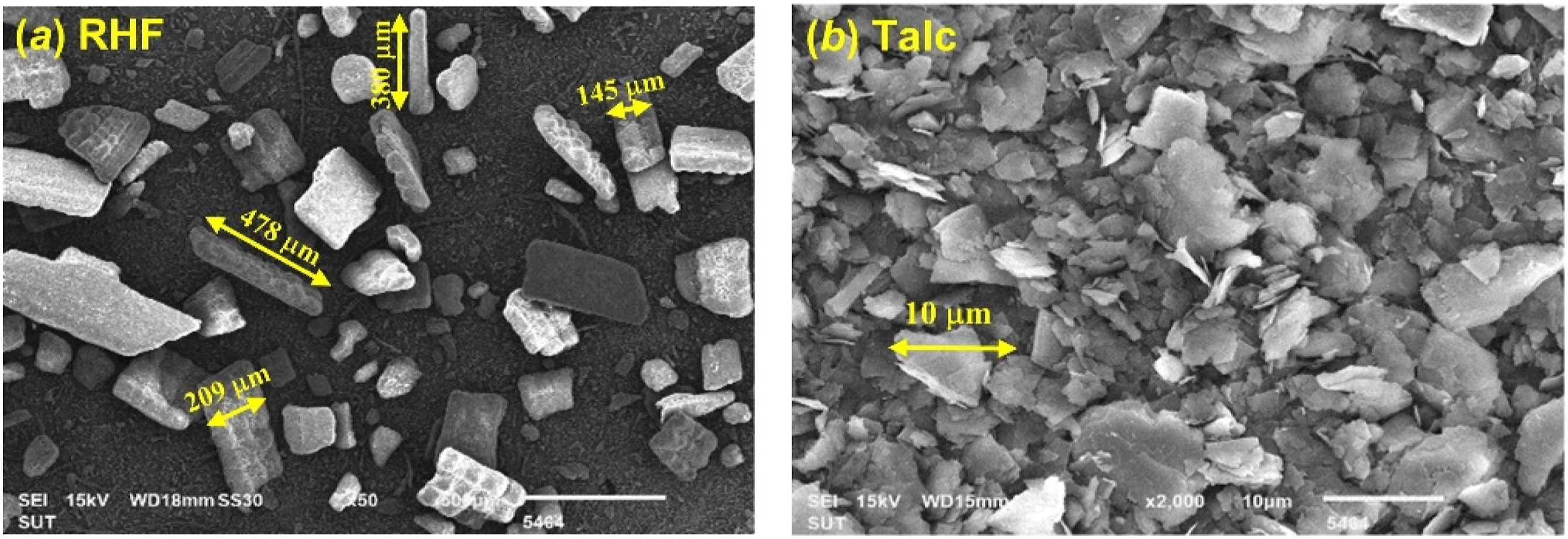
MFI results at the given melt temperatures of materials for WPC compounding.
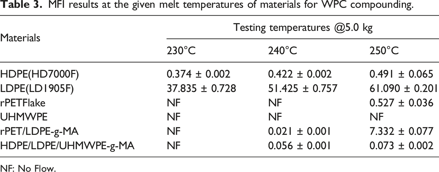
NF: No Flow.
Both (HDPE/LDPE/UHMWPE)-g-MA and (rPET/LDPE)-g-MA blends were prepared by single step melt blending on a twin screw extruder. Then, the MA would be randomly grafted onto individual polymer chains. The existence of MA grafted polymer chains was characterized by FTIR. The possible unreacted MA residual in the blend was removed by precipitation of the blend/xylene solution onto methanol. The FTIR spectra at the wave number 1750 to 2000 cm−1 of (HDPE/LDPE/UHMWPE)-g-MA and HDPE, and (rPET/LDPE)-g-MA and LDPE are presented in Figure 4(a) and (b), respectively. The strong asymmetric C = O stretching at 1791 cm−1 was obviously seen on the (HDPE/LDPE/UHMWPE)-g-MA spectra. Also, medium intensity peak of the symmetric C = O stretching at 1867 cm−1 was evidenced. These two IR peaks are the most common representative stretching for the unsaturated cyclic anhydrides such as maleic anhydride. Therefore, they were the conclusive evidence for the presenting of the MA-grafted chained in (HDPE/LDPE/UHMWPE)-g-MA blend. For (rPET/LDPE)-g-MA spectra, the asymmetric C = O stretching and symmetric C = O stretching at 1791, 1867 cm−1 were also seen with relatively lower intensity than the spectra found in the (HDPE/LDPE/UHMWPE)-g-MA blend. The interference of strong C = O stretching from the ester group of rPET should be the main reason for lowering the C = O anhydride peaks intensity. Regarding these IR characterization results, they could suggest with high confidence that the MA was grafted onto the polymer chains in both (HDPE/LDPE/UHMWPE)-g-MA and (rPET/LDPE)-g-MA blends. Another statement worth to mention from this FTIR characterization, the MA grafting efficiency via the peroxide free radical reaction on the olefin polymer chains, such as PP and PE, is more favor than on the polyester chains.23,24 The qualification and quantification of MA grating on the polymer chains by FTIR analysis were also published and reported.25,26 Therefore, the C = O stretching peaks intensity of MA found on the (rPET/LDPE)-g-MA blend were much lower than in (HDPE/LDPE/UHMWPE)-g-MA. It could manifest that (HDPE/LDPE/UHMWPE)-g-MA had higher MA grafting efficiency than (rPET/LDPE)-g-MA blend. FTIR spectra of (a) (HDPE/LDPE/UHMWPE)-g-M and (b) (rPET/LDPE)-g-MA blends, respectively.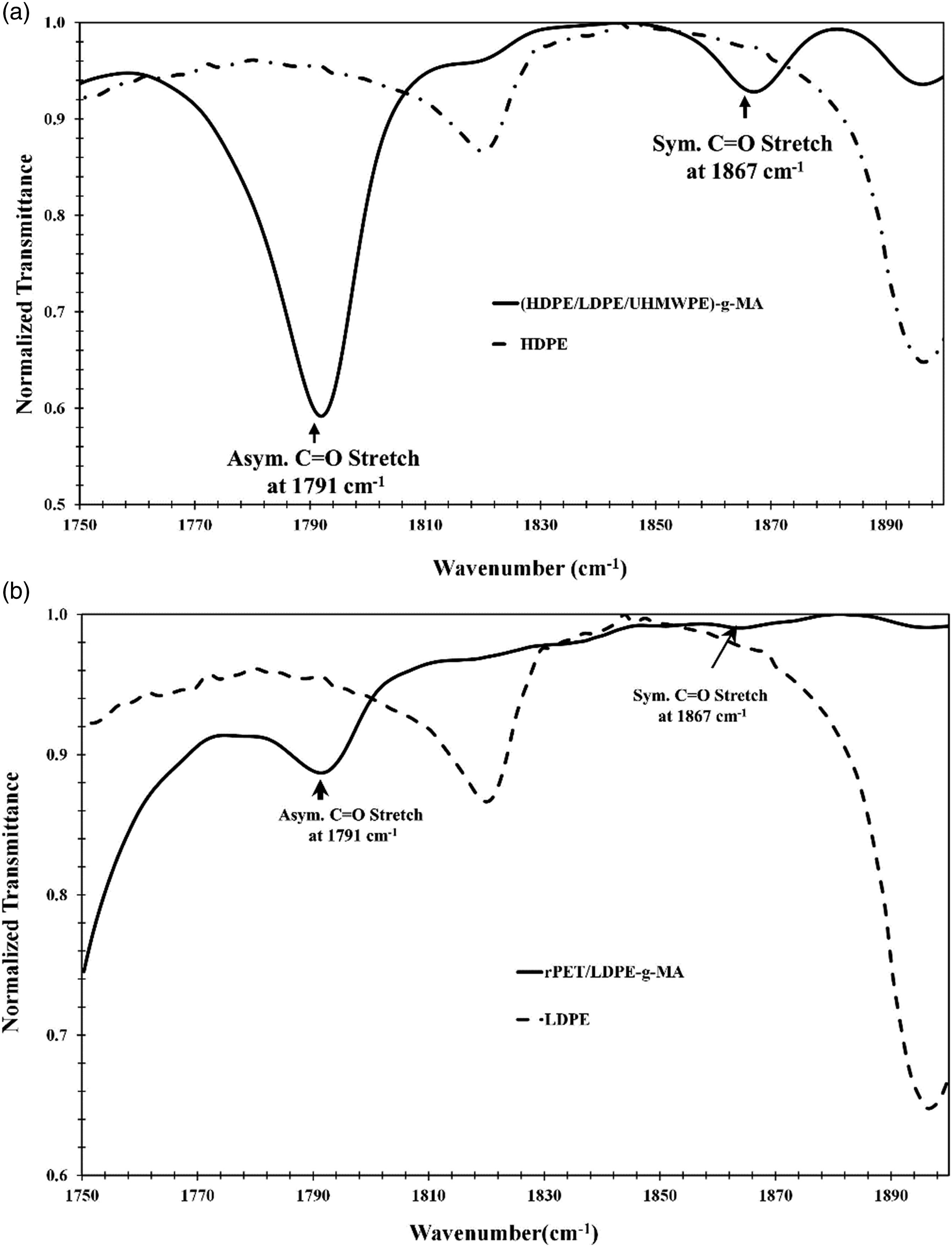
Miscibility or compatibility is a prime engineering concern in polymer blends, especially when blending two or more absolutely different generic polymers. SEM is the most common visual method to observe blend morphology. Figure 5(a) and (b) are the SEM photos of (HDPE/LDPE/UHMWPE)-g-MA at ×400 and ×1000 magnifications, respectively. It was no doubt that the (HDPE/LDPE/UHMWPE)-g-MA blend showed the single-phase material. It was a totally miscible blend. In both photos also reveal the “fibril like skin” fractured surface that was the indication of the toughened fracture traces of UHMWPE. Figure 5(c) and (d) are the fractured surface SEM photos of (rPET/LDPE) and (rPET/LDPE)-g-MA blends at ×1000 magnification, respectively. A totally poor compatible blend between rPET and LDPE was obviously seen on the (rPET/LDPE) blend. However, for the (rPET/LDPE)-g-MA blend, randomly dispersed of very tiny LDPE droplets within the rPET domain phase was evidently visualized. This SEM information strengthened that much better compatibility between rPET, and LDPE blend were obtained via the MA grafting process. SEM Photos of (a) (HDPE/LDPE/UHMWPE)-g-MA at ×400, (b) (HDPE/LDPE/UHMWPE)-g-MA at X1000, (c) (rPET/LDPE) and (d) (rPET/LDPE)-g-MA at ×1000, respectively.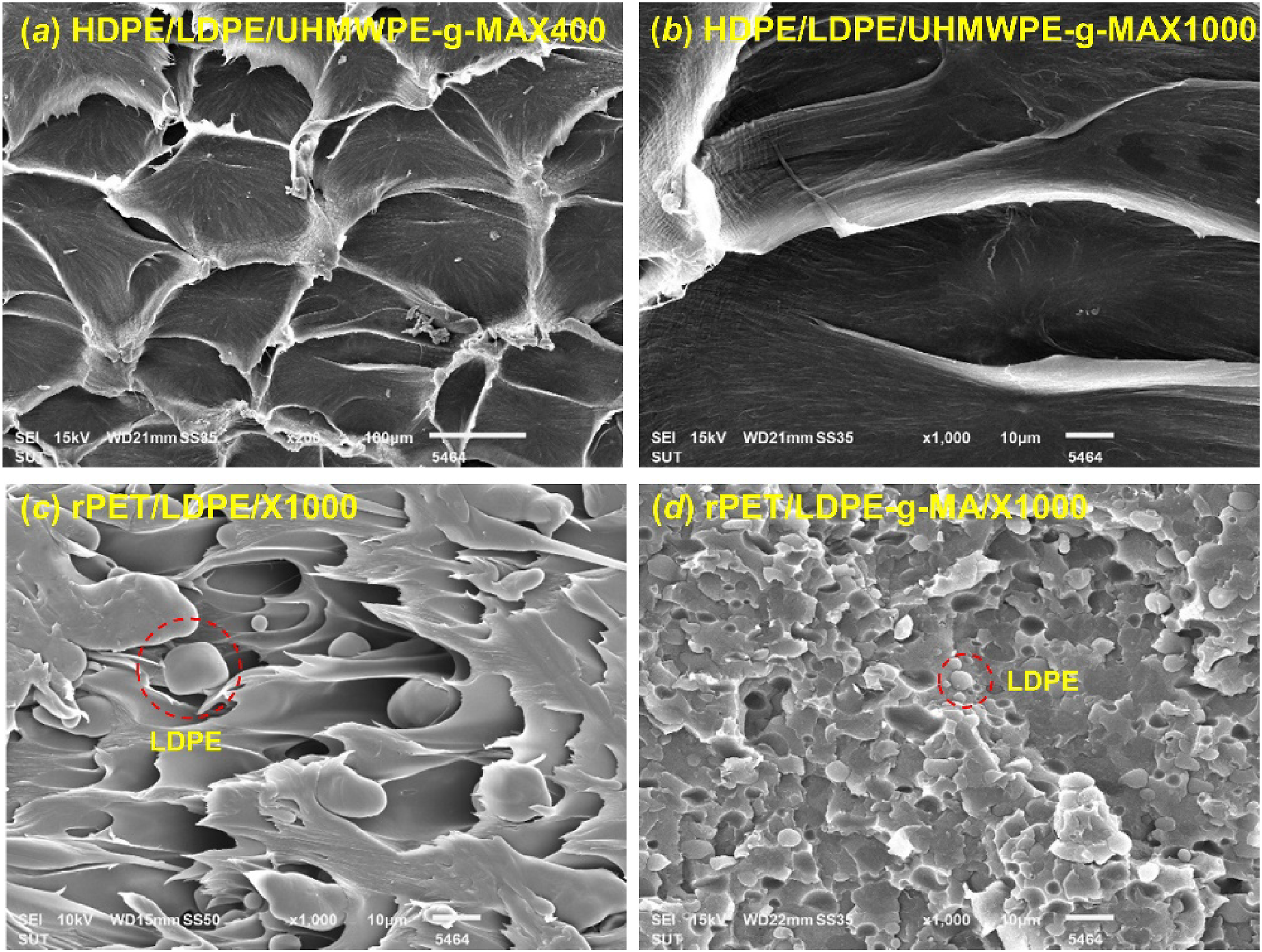
Effect of (HDPE/LDPE/UHMWPE)-g-MA and (rPET/LDPE)-g-MA blends ratios as blended matrices on properties of manufactured WPC
WPC formulations at assigned (HDPE/LDPE/UHMWPE)-g-MA and (rPET/LDPE)-g-MA blends ratios.
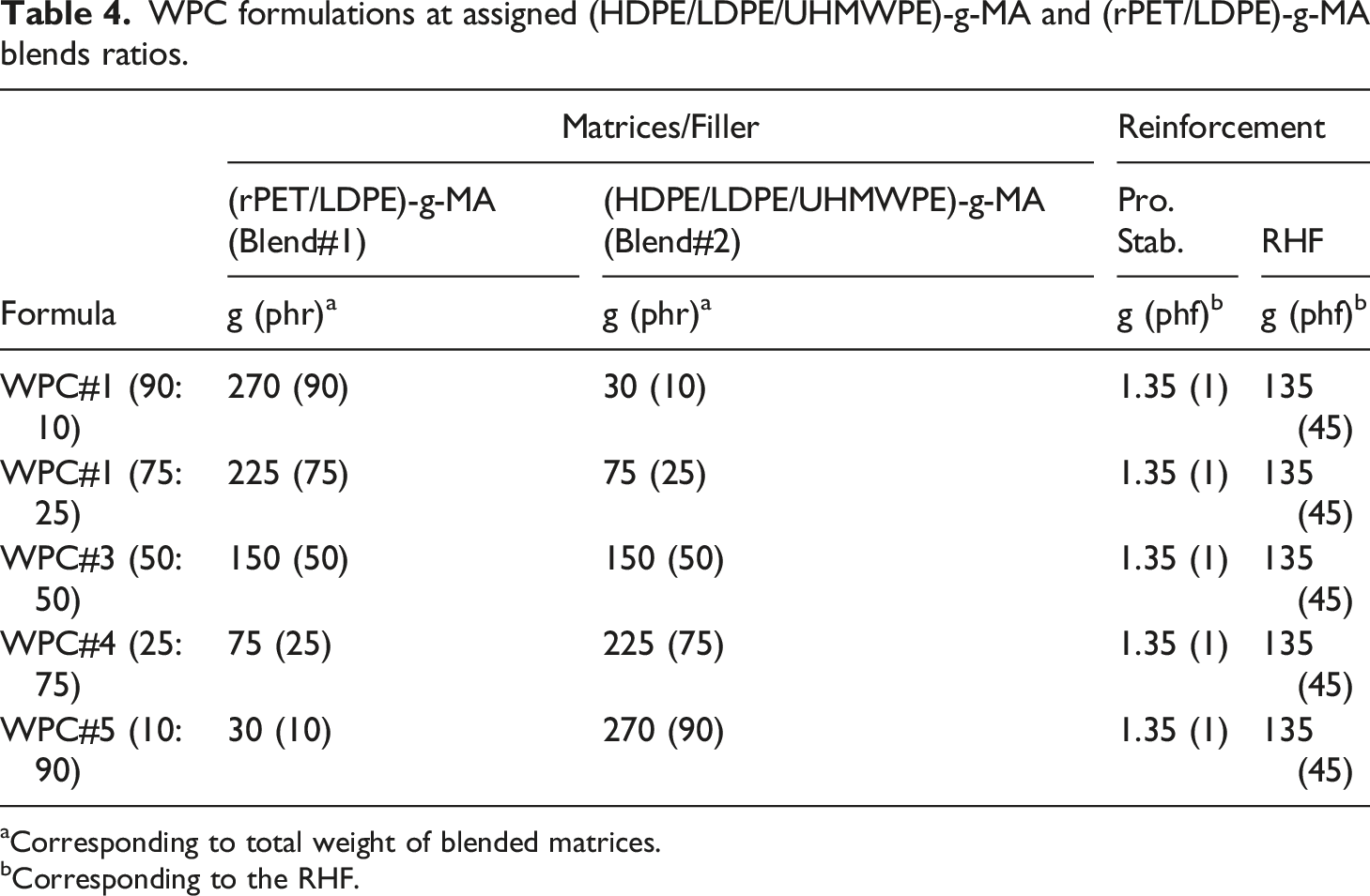
Corresponding to total weight of blended matrices.
Corresponding to the RHF.
The breakdown composition by weight of polymers in the blended matrices.
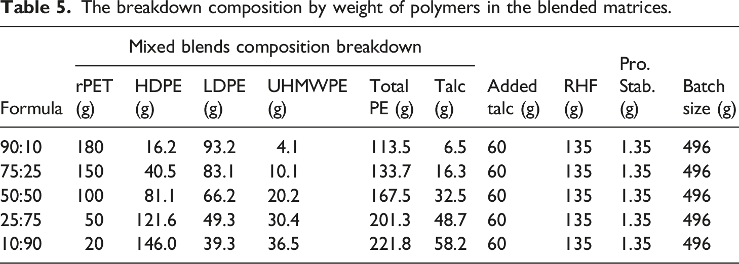
Figure 6 shows the SEM photos taken at the fractured surface of the notched impact WPC specimen produced from (rPET/LDPE)-g-MA and (HDPE/LDPE/UHMWPE)-g-MA blended matrices at weight ratio of 90:10, 75:25, 50:50 and 10:90, respectively. Observing on the matrix phase, it was seen that there was no obvious phase separation between rPET and the generic PE polymers. Only thin plate flake of talc filler and “fibril like” traces of UHMWPE toughener were clearly observed. The density of talc flake and UHMWPE fibril traces were clearly increased upon decreasing the blends ratios from 90:10 to 10:90, respectively. These SEM evidences were in good agreement with the weight breakdown composition shown in Table 5. The UHMWPE toughener and total talc filler contents were increased from 90:10 to 10:90 blend ratio, respectively. Observation between RHF surface and blended matrices interface, it was obvious that relative clean RHF surface was noticed at 90:10 ratio. Increasing in the adhered traces risen from the blended matrices on the RHF surface were observed when the (rPET/LDPE)-g-MA ratio in the blended matrices was decreased. Also, SEM result clearly demonstrated that poor fiber/matrices interfacial adhesion was revealed on the WPC produced from 90:10 blends ratio. Gradual enhancement of the interfacial bonding was detectable when the blend ratio was progressively increased to 10:90. It manifested that better RHF/matrices interfacial adhesion was established when low (rPET/LDPE)-g-MA ratio was employed in the blended matrices. Referring to the previous FTIR discussion, (HDPE/LDPE/UHMWPE)-g-MA blend had higher MA grafting efficiency than (rPET/LDPE)-g-MA. Consequently, the RHF/matrices interfacial adhesion should be enhanced by increasing the (HDPE/LDPE/UHMWPE)-g-MA ratio on the blended matrices because the grafted MA was preferably reacted with the cellulosic RHF to form the strong chemical interfacial surface bonding. Increasing in UHMWPE toughener fraction and the enhancement of the fiber/matrices interfacial bonding upon increasing the (HDPE/LDPE/UHMWPE)-g-MA ratio on the blended matrices must have a significant positive effect on the mechanical performance of the WPC. Finally, the SEM analysis showed no evidence of microfibril formation of rPET within the domain phase of the inclusive PEs matrix.
27
SEM photos at ×400 for WPC manufactured from (rPET/LDPE)-g-MA and (HDPE/LDPE/UHMWPE)-g-MA blended matrices at the ratio of (a) 90:10 (b) 75:25, (c) 50:50 and (d) 10:90, respectively.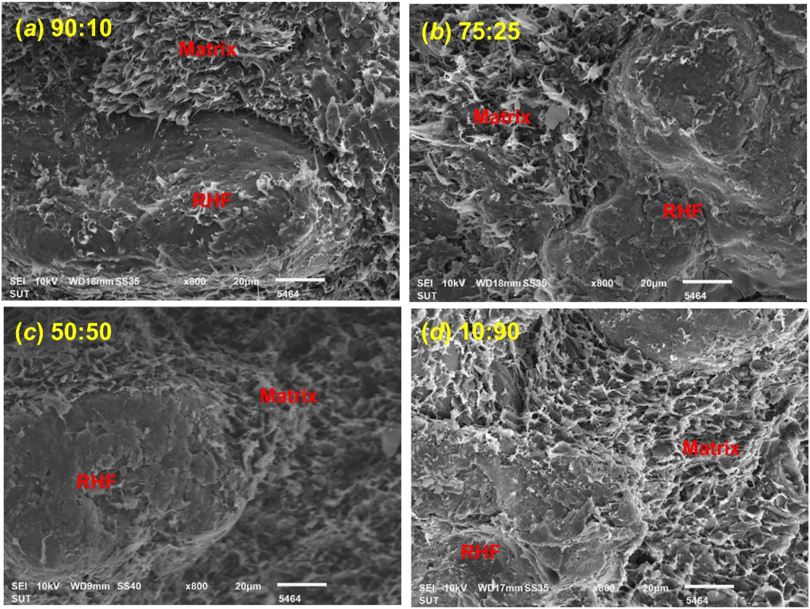
The rheological property, obtained as MFI, of the WPC manufactured from the (rPET/LDPE)-g-MA and (HDPE/LDPE/UHMWPE)-g-MA blended matrices at various blend ratios was conducted at 230/5.0. Test results versus blend ratios were graphically presented in Figure 7. It was noticed that the MFI was raised from 0.044 to 0.070 g/10 min when (rPET/LDPE)-g-MA ratio was decreased from 90:10 to 50:50. After that, the declining trend of MFI was observed by further reducing (rPET/LDPE)-g-MA ratio to 10:90. From the material principle viewpoint, the rheological property of fiber reinforced material is chiefly depended on matrix type and on both fiber characteristic and content. In this study, RHF loading was identically assigned at 45 phr for all WPC formulations. Only the ratios of the blends as the blended matrices were varied. According to the weight breakdown composition given in Table 5, rPET content was reduced but the total weight of generic PE polymers and talc filler loading were increased when the ratios were increased from 90:10 to 10:90, respectively. The talc filler employed in this study is categorized as a property enhancement filler and it normally acts as solid lubricant at certain loading.
28
With regard to the employed rPET and UHMWPE toughener, flowability of both polymers require high melting temperature. As concluded in Tables 1 and 6, a melting temperature exceeding 300°C was necessarily acquired for good flowability of both polymers. At the standard assigned melt temperature at 230°C for MFI testing conducted in this work, the influence of rPET and UHMWPE toughener contents must be the prime suspect on the MFI results of the obtained WPC. Obeying the MFI results shown in Table 3, the flowable melt temperature of rPET was lower than UHMWPE. Also, the melt temperatures of HDPE and LDPE were much lower than rPET. Then, both HDPE and LDPE would not have a significant effect and contribution on the flowability of the blended matrices at 230°C. Regarding the obtained MFI outcome, it could be hypothesized that the MFI of WPC manufactured from the (rPET/LDPE)-g-MA and (HDPE/LDPE/UHMWPE)-g-MA blended matrices at 90:10 to 50:50 weight ratio was controlled by the rPET fraction. The increase in MFI was due to the decreasing in high rPET content which has high melting point. Further decreasing in the (rPET/LDPE)-g-MA blend ratios from 50:50 to 10:90, the flowability of the obtained WPC material was regulated by UHMWPE contents. The flowability of WPC was reduced by increasing UHMWPE fraction. Referring to the weight breakdown composition, rPET was the domain phase for the blended matrices at high (rPET/LDPE)-g-MA ratio, for example at 90:10. Meanwhile, a small weight fraction of UHMWPE which was completely miscible/soluble with LDPE and HDPE phase. Accordingly, the single-phase blended polymer comprised of UHMWPE, LDPE and HDPE was played as the disperse phase. In addition, high melt viscosity of UHMWPE was reduced and compensated by the easy flow characteristic of HDPE and LDPE as seen in Table 3. Therefore, the flowability of the blended matrices contained high ratio of (rPET/LDPE)-g-MA blend at 230°C was mainly dominated by molten rPET. The weight fraction of rPET was reduced upon decreasing of (rPET/LDPE)-g-MA ratio in blended matrices. Subsequently, MFI of molten WPC must be increased. At 50:50 ratio, the inverse phase of the blended matrices was occurred as indicated in Table 5. The complete miscible polymers blend of UHMWPE, HDPE and LDPE became the domain phase. Meanwhile, rPET was inverted into the disperse phase. Consequently, the flowability of the blended matrices should be regulated by the rheological means of the miscible PE polymers blend domain phase. Moreover, the weight fraction of UHMWPE in the miscible PEs blend was increased upon decreasing in (rPET/LDPE)-g-MA ratio or increasing in (HDPE/LDPE/UHMWPE)-g-MA ratio. Hence, the viscosity of the molten domain phase must be increased. Accordingly, the MFI of WPC must be progressively reduced upon reducing the (rPET/LDPE)-g-MA blend ratio from 50:50 to 10:90, respectively. MFI of WPC versus (rPET/LDPE)-g-MA and (HDPE/LDPE/UHMWPE)-g-MA ratios. WPC formulations with varied DCP/VTMS crosslink agent’s ratios. Corresponding to total weight of blended matrices. Corresponding to RHF.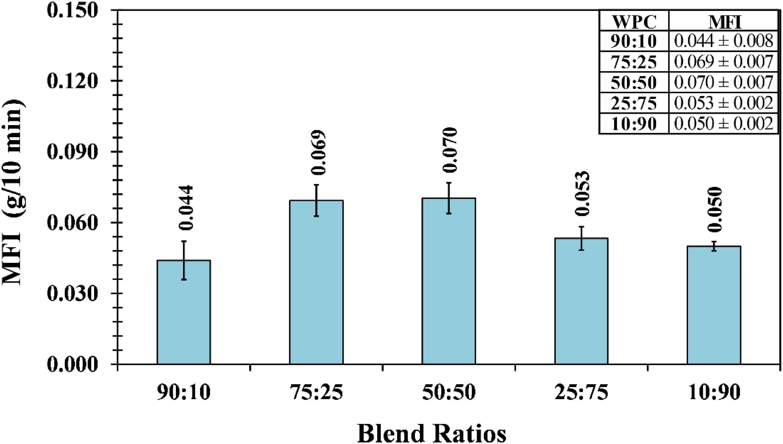
The effect of the blends ratios as the blended matrices on HDT of the manufactured WPC was measured at 455 kPa standard load. The HDT results were plotted against ratios and presented in Figure 8, respectively. It was seen that HDT was gradually increased from approx. 67°C–96°C when (rPET/LDPE)-g-MA blend ratios were decreased from 90:10 to 25:75, correspondingly. An almost insignificant change in HDT was observed upon further reducing the ratio to 10:90. For the fiber reinforced materials, HDT is typically dependent on matrix, filler, fiber characteristic/content, and matrix/fiber interfacial adhesion. In this study, identical RHF at 45 phr content was used in all WPC formulations. Then, the blended matrices, talc filler and interfacial bonding must be the main influences on the HDT of WPC. Referring to the polymeric raw materials data concluded in Table 1, typical HDT of LDPE, HDPE, UHMWPE and PET are <25°C, 60°C, 85°C and 75°C, respectively. Theoretically, by obeying the “rule of mixture,” the HDT of the blended matrices should be increased upon decreasing the (rPET/LDPE)-g-MA ratio. As given in Table 5, it was because of that rPET and LDPE fractions in the blended matrices were decreased but the fraction of high HDT polymers, comprised of HDPE and UHMWPE, were increased. Then, the HDT of WPC must be elevated. At 90:10 ratio, it was observed that the HDT of WPC was obviously lower than HDT of rPET. It could be justified by the high weight fraction of the extra low HDT characteristic of LDPE. The effect of low HDT from LDPE was gradually less pronounced when (rPET/LDPE)-g-MA blend ratio was decreased. Moreover, it was seen that the HDT values of WPC at high (HDPE/LDPE/UHMWPE)-g-MA ratio were higher than the HDT of UHMWPE which is at 85°C. This observation should be explained by the RHF/matrices interfacial adhesion enhancement. As discussed in the SEM analysis, the improvement on RHF/matrices interfacial bonding was accomplished upon reducing the (rPET/LDPE)-g-MA or increasing (HDPE/LDPE/UHMWPE)-g-MA ratios. This interfacial enhancement must have a positive effect on the reinforcing efficiency of RHF. Subsequently, the HDT of WPC manufactured from (rPET/LDPE)-g-MA/(HDPE/LDPE/UHMWPE)-g-MA/RHF with great fiber/matrix adhesion bonding must have higher HDT than of the WPC material with low fiber/matrix adhesion. HDT of WPC manufactured from the blended matrices at the given blends ratios.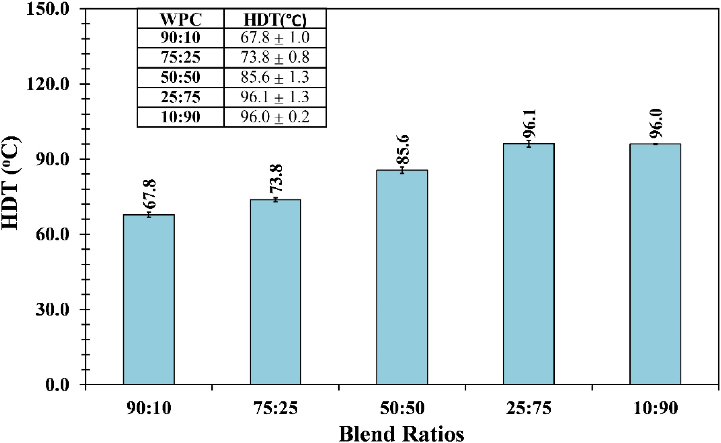
The impact toughness of WPC at the given blends ratio was measured by notched and unnotched modes. The results were plotted against blends ratios and presented in Figure 9. It was seen that the unnotched impact strength was reduced when (rPET/LDPE)-g-MA blend ratios were decreased from 90:10 to 75:25. After that, the strength was almost unchanged with the ratios. Vice versa, slow rising trend in the notched impact strength was seen when (rPET/LDPE)-g-MA ratios were declined from 90:10 to 50:50. The obvious increase in the strengths were observed when the ratios were further reduced from 50:50 to 10:90. For the unnotched impact strength of the fiber reinforced composite material that is manufactured from the identical fiber characteristic and loading, the impact toughness is commonly obeyed on matrix performance and perhaps interfacial adhesion. PET is considerably superior in unnotched impact strength to PE polymers, except for UHMWPE. According to these polymers performances, the unnotched impact strength of the produced WPC should be reduced when (rPET/LDPE)-g-MA blend ratios were reduced from 90:10 to 75:25. Referring to the above SEM remark and the polymeric breakdown composition, interfacial bonding enhancement and obvious increase in UHMWPE fraction were occurred upon reduction of (rPET/LDPE)-g-MA ratio. These two phenomena had a positive effect on the unnotched impact strength and could have an add-on compensation to unnotched impact strength loss due to the rPET fraction reduction. As such rationalization, further inferiority on unnotched impact toughness caused by rPET fraction diminishing was not experienced. Therefore, a constant trend in the unnotched impact strength was revealed from 75:25 to 10:90 blends ratios. In the case of the notched impact outcomes, matrix and interfacial bonding must play the important roles for the impact enhancement. PET is well known for having higher notch sensitivity than PE polymers. Therefore, the notched impact strength would be increased upon reducing the rPET fraction as visualized from 90:10 to 50:50 ratios. In addition, the fiber/matrices interfacial adhesion enhancement and increasing of talc filler loading would have a further positive contribution to the notched impact improvement. Moreover, the most obvious notched impact strengths advancement were seen from 50:50 to 10:90 blend ratios. As previously mentioned, the domain phase inversion from rPET to the UHMWPE/PEs miscible blend was occurred when the blends ratio was exceeded 50:50. Moreover, the UHMWPE toughener fraction was obviously dominated from 25:75 to 10:90 ratios. For such reasons, the notched impact of the WPC produced from these given ratios were clearly and obviously enhanced. Notched and Unnotched impact strengths of WPC manufactured from the blended matrices at the given blends ratios.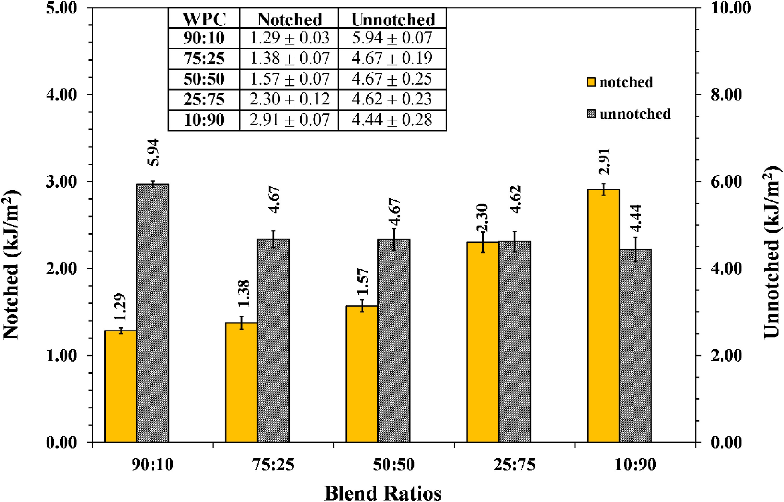
The rupture toughness by means of three point bending flexural testing was conducted at 80 mm span length and 15 mm/min deformation rate. The obtained flexural strength, modulus and deformation at break were plotted versus blends ratios and illustrated in Figure 10. The result in Figure 10(a) revealed that the flexural strength was almost unchanged with the blends ratio on the blended matrix. The flexural modulus shown in Figure 10(a) was slowly increased when (rPET/LDPE)-g-MA ratio was decreased. Meanwhile, in Figure 10(b), the deformation at break was slowly increased when the (rPET/LDPE)-g-MA ratio was decreased from 90:10 to 25:75 and the sudden increase in the deformation at break was noticeably observed at 10:90 ratio. Commonly, similar to impact testing, flexural interpretation is the measurement of material toughness under constant deflection rate. The rupture energy required for breaking the test specimen is calculated from the integrated area under the load versus displacement plot. Basically, increasing in the flexural strength, modulus and deformation at break are referred to rising in the rupture energy. Consequently, enhancement of the flexural toughness of material is concluded. According to the obtained flexural characteristics of the WPC upon reducing (rPET/LDPE)-g-MA ratios or increasing (HDPE/LDPE/UHMWPE)-g-MA ratios, it could be proposed that the flexural toughness of the obtained wood composite was superior upon reducing the (rPET/LDPE)-g-MA ratio in the blended matrix. The enhancement of the flexural toughness could be explained by two stages. First stage was at 90:10 to 50:50 blends ratios where the modulus and deformation at break were barely increased. In fact, the flexural toughness should be declined because the good flexural strength rPET fraction was reduced. In contrast, interfacial bonding advancement between RHF and the blended matrices was found to be enhanced at this stage. Possibly, the decline on the flexural properties due to the reduction of rPET fraction was conquered by the adhesion bonding strength superiority. Consequently, the ambiguous sign of the flexural toughness enhancement was visualized. At the domain phase reversion stage and beyond, 25:75 to 10:90 ratios, greater interfacial adhesion plus higher in of UHMWPE toughener fraction was acquired. These two positive effects must have a significant influence and contribution to the flexural toughness improvement of the WPC. (a) Flexural strengths and modulus, and (b) deformation at break of WPC manufactured from the blended matrices at the given blends’ ratios, respectively.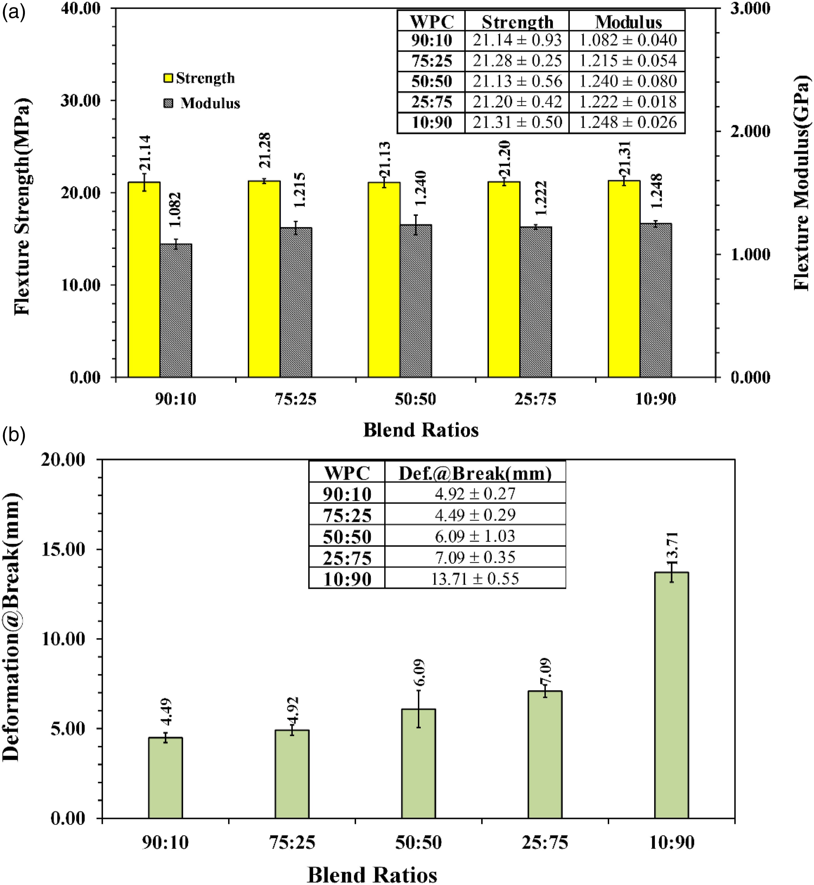
Figure 11(a) and (b) are the plots of tensile properties by means of ultimate strength, modulus, and % elongation at break of the WPC manufactured from the blended matrices at the given blends ratios. The ultimate tensile strength in Figure 11(a) revealed that it was slowly decreased from 16.62 to 13.24 MPa by reducing (rPET/LDPE)-g-MA ratios from 90:10 to 10:90, respectively. Meanwhile, the modulus was seen to be increased from 2.318 to 2.640 GPa upon reduction of the ratios from 90:10 to 50:50. Further ratios reduction to 10:90, the doubtful down trend on the modulus was observed. For the % elongation at break, shown in Figure 11(b), it was slowly decreased when the blends ratios declined from 90:10 to 50:50. But, the rising trend was seemly picked up again when the ratios were exceeded 50:50. Obeying material ductility and brittleness principles, these obtained tensile characteristics could be explained into two stages. The first stage was at 90:10 to 50:50 ratios. The tensile outcomes showed that ultimate strength and % elongation at break were declined upon reducing of (rPET/LDPE)-g-MA ratio. Vice versa, the modulus was in the slow rising trend. According to these measured tensile features, they could be rationalized that the ductility of the obtained WPC was decreased with reducing (rPET/LDPE)-g-MA ratio. As manifested in the breakdown polymers compositions in Table5, high ductility rPET was the domain phase for the blended matrices and its weight fraction was reduced upon (rPET/LDPE)-g-MA ratios reduction. Those blended matrices were reinforced with brittle RHF reinforcement. Then, the ductility of the obtained WPC should be reduced due to the decreasing of rPET fraction. Moreover, progressive fiber/matrices interfacial improvement was demonstrated at low rPET fraction. Then, the brittleness characteristic of RHF reinforcement could be gradually contributed into the WPC tensile property. Moreover, the increase in the talc filler loading was worth mentioning. Generally, the tensile ductility of polymer compound is diminished by increasing the talc filler loading. By summing up those phenomena, reduction of the WPC ductility upon decreasing (rPET/LDPE)-g-MA ratio from 90:10 to 50:50 must be justified. However, at the inversed phase blends ratio at 50:50 and beyond, the ductility of the manufactured wood composites were retained. Ambiguously, the sign of toughness improvement was noticed upon further decreasing of (rPET/LDPE)-g-MA (or increasing (HDPE/LDPE/UHMWPE)-g-MA) ratios. It could be the fact that the fraction of miscible PEs blends, inclusively UHMWPE, was increased at beyond reverse phase blends ratio. PE polymers are typically well known as one of the high elastomeric materials. Then, the brittleness of the obtained WPC was gradually overthrown upon rising in the miscible PEs blends content. Hence, the improvement of the tensile ductility of WPC was noticed at high (HDPE/LDPE/UHMWPE)-g-MA ratio. (a) Ultimate tensile strengths and modulus, and (b) Elongation at break of WPC manufactured from the blended matrices at the given blends ratios, respectively.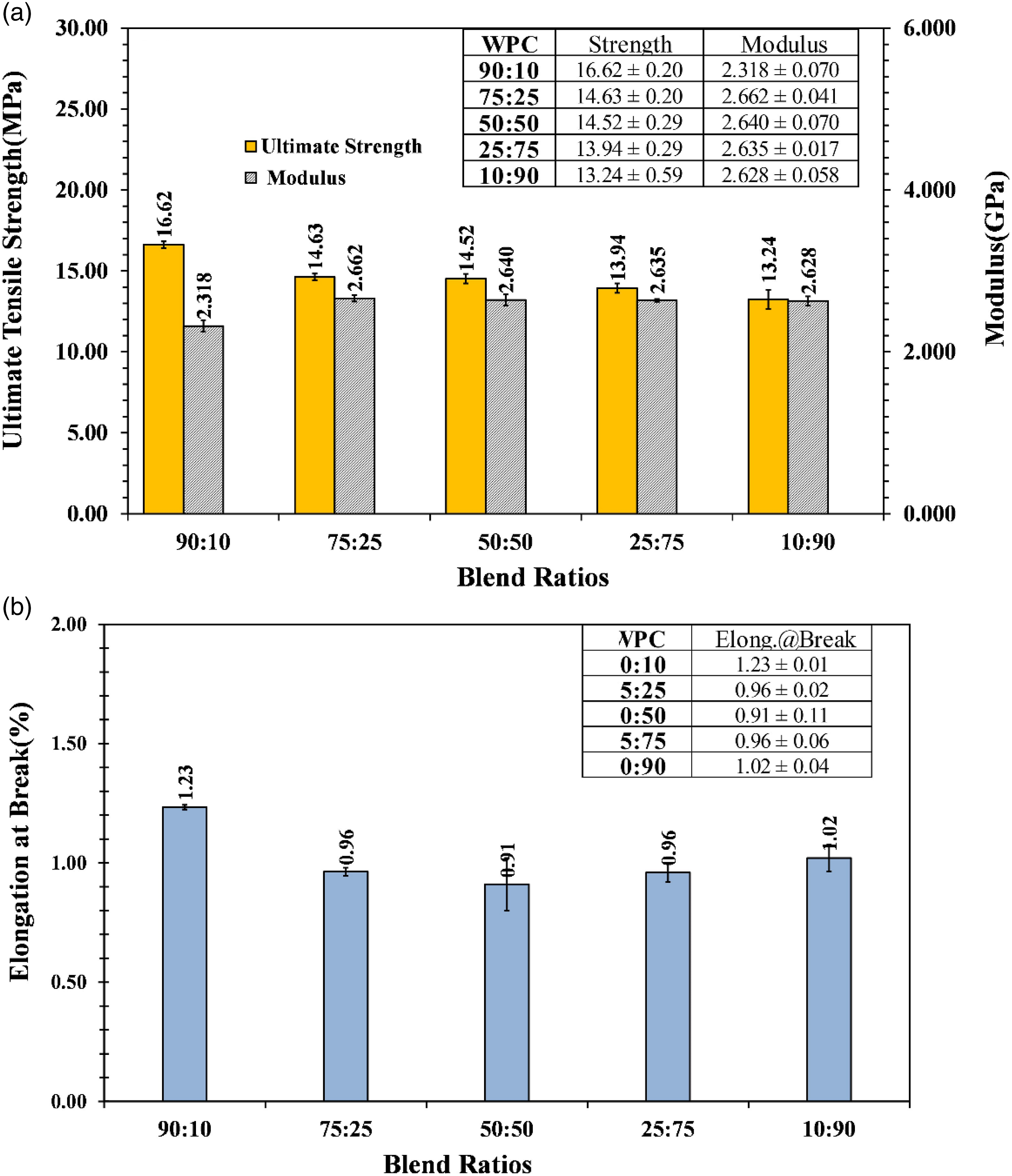
The durability by means of % water absorption and % dimensional swelling or shortly as % swell under prolonged water immersion for 1- and 7-days of the WPC manufactured from (rPET/LDPE)-g-MA/(HDPE/LDPE/UHMWPE)-g-MA blended matrices at the given blends ratios were analyzed. The obtained test values versus blends ratios were plotted and presented in Figure 12. Obviously, in Figure 12(a), the 1-day % water absorption for all blends ratios as shown were less than 1.0% and it was merely decreased when (rPET/LDPE)-g-MA ratio was decreased. Similarly, % absorption results for 7-days water immersion for all samples were approximately 1% and ambiguously reduced upon reduction of (rPET/LDPE)-g-MA ratio. rPET is one of the polyester types. It is well established that the hydrophilicity of polyester is much higher than the olefin polymer. Certainly, % water absorption of the manufactured WPC must be reduced when rPET fraction in the blended matrices was decreased. Another point worth mentioning is the interfacial adhesion between RHF and blended matrices. As concluded in SEM analysis that enhancement of interfacial bonding was achieved when (rPET/LDPE)-g-MA ratio was reduced. Then, the lower in (rPET/LDPE)-g-MA ratio the tighter in RHF interfaces adhesion. Accordingly, water diffusion into the micro interface gap via the capillary force was diminished upon the enhancement of interfacial adhesion. Obeying on these two events, % water absorption must be minimized and reduced at low (rPET/LDPE)-g-MA ratio. For % dimensional swelling results shown in Figure 12(b), the declining trend upon reducing (rPET/LDPE)-g-MA ratio was clearly seen on both 1- and 7-days immersion. All the measured % swelling values were obviously less than 1%. Especially at 10:90 ratio, only 0.2% swelling was recorded. It was no doubt that % swelling must be directly related to % water absorption. Regardless of the immersion period, the greater in % water absorption the higher in the hydro static pressure building up inside the WPC sample. Thus, the % dimensional swelling value must be increased accordingly. In conclusion, % water absorption of the WPC was decreased when high hydrophilic rPET content in the blended matrices was reduced. Subsequently, a low level of % swelling value must be established due to the insufficient hydro static pressure from low % water absorption. (a) Moisture absorption (%), and (b) % swelling of the WPC manufactured from the blended matrices at the given blends ratios, respectively.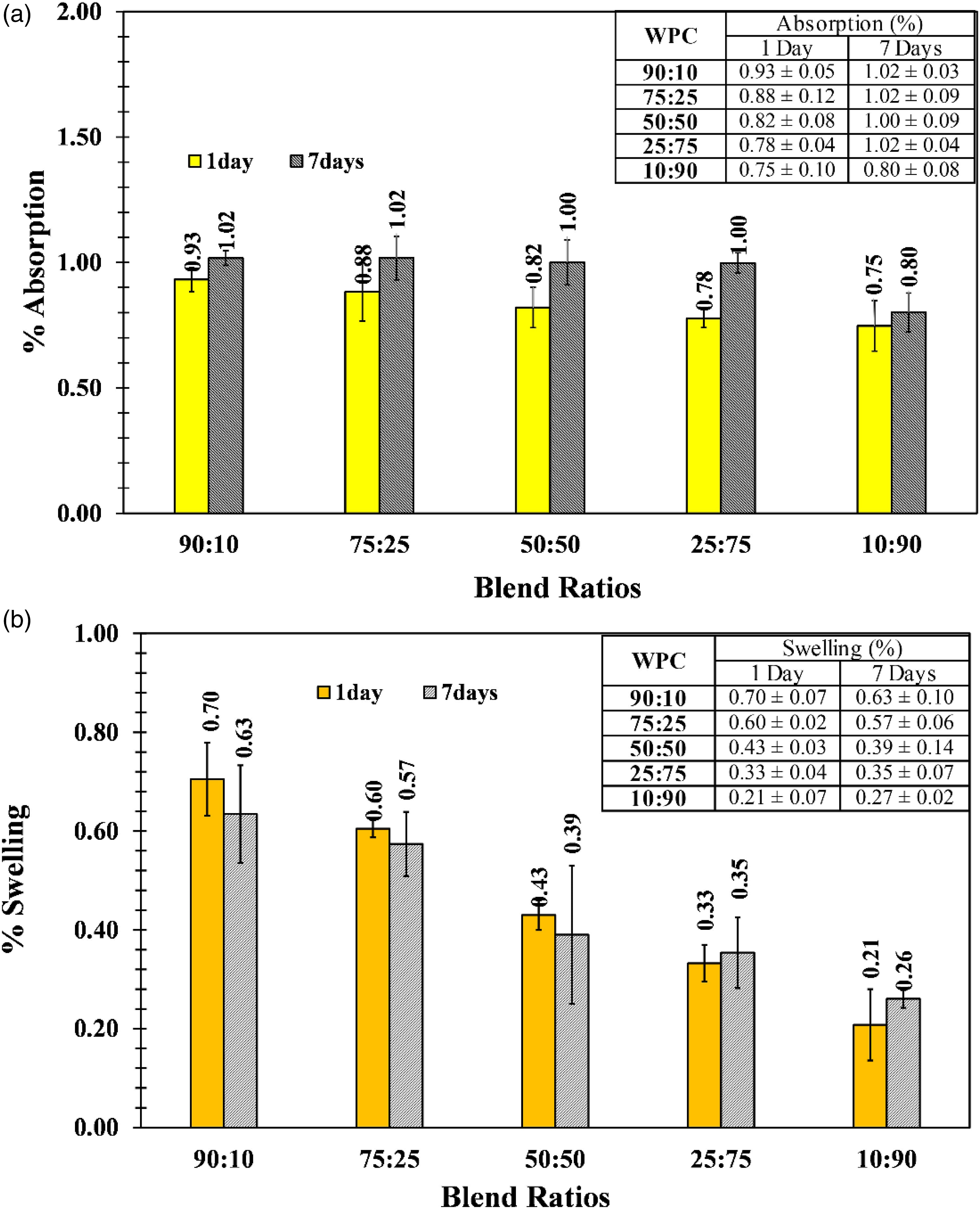
Peroxide/silane macro crosslinked XWPC
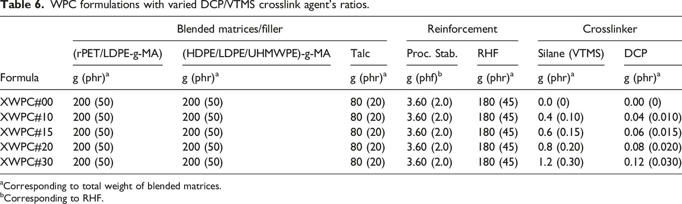
The macro crosslink formation using peroxide/silane system was explored on the (rPET/LDPE)-g-MA/(HDPE/LDPE/UHMWPE)-g-MA/RHF wood composite manufacturing. DCP and vinyltrimethoxy silane (VTMS) crosslinker system was employed. The assigned XWPC formulations regarding DCP/VTMS ratios and other ingredients are summarized in Table 6. (rPET/LDPE)-g-MA and (HDPE/LDPE/UHMWPE)-g-MA blends ratio was constantly assigned at 50:50. The added talc, thermal/processing stabilizer and RHF contents were at 45 phr, 2.0 phf and 45 phr, respectively. The DCP/VTMS ratios were varied from 0.00/0.000 to 0.30/0.030. The designed XWPC formulations were denoted as XWPC#00 to XWPC#30, respectively. All XWPC formulations were compounded and then injection molded into test pieces at the processing temperature did not exceed 240°C. In order to accelerate the macro crosslink reaction to form siloxane bonding bridges (-Si-O-Si-), half of the injected specimens were undergone sauna incubation in tightly closed moisture saturated oven at 90°C for 6 h (Zhou et al. 2009). After that, the residual moisture on the sauna cured XWPC sample was removed by vacuum drying at 90°C for 3 h prior to testing. These samples were called “cured” XWPC samples. The other half of the injected specimens were annealed under atmospheric condition for 24 h prior to testing and they were called “original” in this work.
Figure 13 shows the SEM photos of the XWPC manufactured using the DCP/VTMS ratios as crosslinker system at 0.00/0.000, 0.10/0.010, 0.20/0.020 and 0.30/0.030, respectively. SEM photos were taken from the fractured surfaces of original and cured notched impact strength test samples. In all original samples, the “fibril like” traces risen from UHMWPE were clearly seen on the surface of the blended matrices. In contrast, the UHMWPE toughener traces were obvious only for the cured XWPC#00 sample. For the other “cured” samples manufactured from DCP/VTMS crosslinker, the “elastomeric bridges like” was apparently seen on the matrix fractured surface and at RHF/matrix interface. These elastomeric traces could be formed due to the presenting of macro crosslinked PE chains via the “moisture induced condensation reaction of the silane grafted chains”.29–31 Observation on the surface of RHF, it was clearly noticed that the relative clean RHF surface was found on the original XWPC#00. The RHF surface adhered with the blended matrices was obviously observed on all the original DCP/VTMS loaded XWPC samples. Furthermore, these matrices adherence phenomena were clearly visualized on all cured macro crosslinked XWPC specimens. At the interfacial surface adhesion area, good interface bonding was seen in all XWPC samples, with and without DCP/VTMS addition. However, the “elastomeric bridges like” between blended matrices and RHF surfaces was obviously visualized only on the cured DCP/VTMS macro crosslinked XWPC samples regardless of the dosing ratios.
32
This piece of visual evidence could manifest that the formation of macro crosslinked structure had promoted the physical/chemical bonding between RHF and blended matrices. Consequently, the mechanical performances of the manufactured macro crosslinked XWPC must have a significant positive effect from this phenomenon. SEM photos of XWPC at the given DCP/VTMS ratios.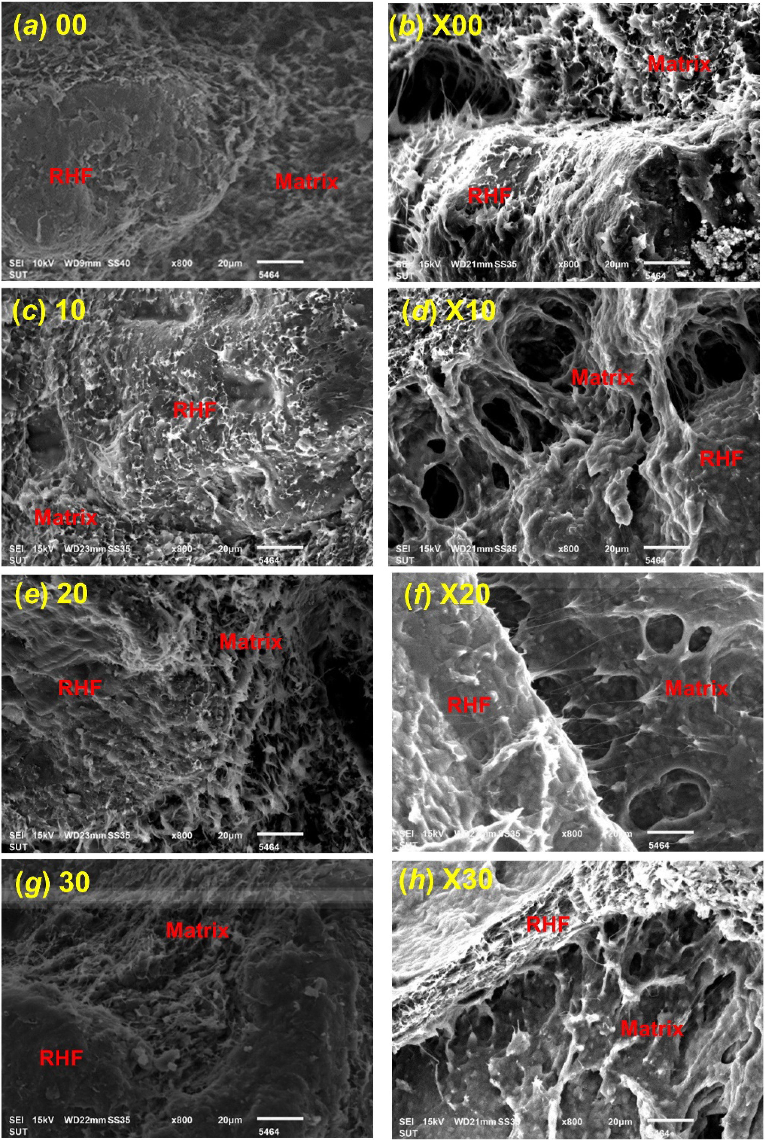
The rheological characteristic under static loading of the macro crosslinked XWPC was analyzed by MFI testing. The obtained test values versus DCP/VTMS ratios loading were plotted and presented in Figure 14. It was undoubtedly revealed that the MFI results of both original and cured XWPC were decreased from 0.083 to 0.014 g/10 min and from 0.055 to 0.013 g/10 min when DCP/VTMS ratios were increased from 0.00/0.000 to 0.30/0.030, respectively. The exponential declining trend of MFI was obviously seen from 0.00/0.000 to 0.15/0.015 ratios. In comparison for all formulations, MFI of the cured samples were apparently lower than the original ones. As expected, greater crosslink density must be formed when higher DCP/VTMS ratio was employed. For the original sample, the main chemical reaction product in the blended matrices would be silane grafted chains. Meanwhile small amount of the pre-matured macro crosslinked structure caused by residual atmospheric moisture reaction during twin screw compounding and sample injection molding should be included as small minor fraction. After undergoing sauna incubation, the completed macro network structure must be formed. The higher in DCP/VTMS ratio dosing the greater in the silane grafted chains density. Consequently, the greater in the macro crosslinked chain density must be obtained after sauna incubation process. Surely, melt viscosity of high macro network density XWPC must be very viscous. Thus, a low measured MFI value must be recorded. From this MFI outcome, it suggested that macro network chains formation induced by DCP/VTMS crosslinker had a significant effect on the flowability of the XWPC. Therefore, to diversify the physical and mechanical properties of the XWPC by using DCP/VTMS crosslinker, the quantity of these chemicals must be carefully designed. With respect to all obtained MFI results, the measured values seem to be very low, less than 0.100 g/10 min. However, at these MFI magnitudes, the flowability or melt processability of XWPC can be managed, especially by extrusion based processors. For industrial applications consideration, most of the WPC products are typically fabricated by die equipped extrusion machine processor. MFIs of XWPC against DCP/VTMS ratios.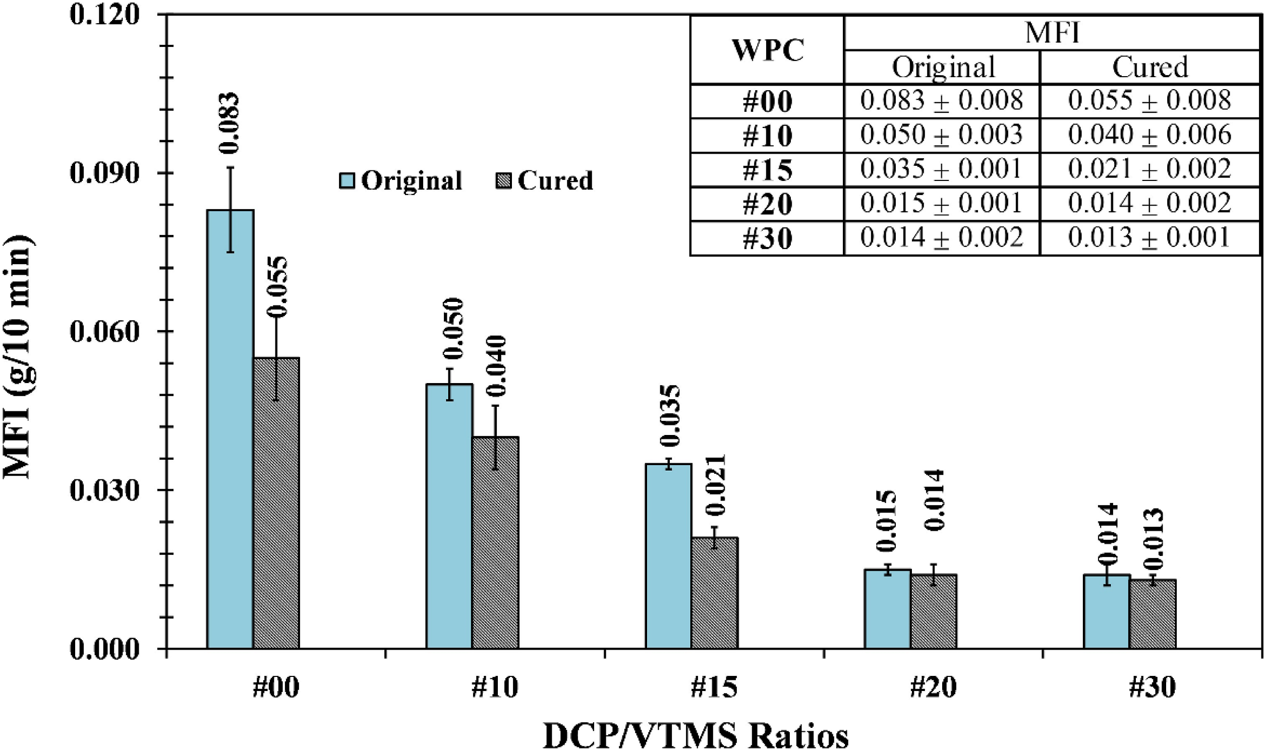
The service temperature of the XWPC fabricated from (rPET/LDPE)-g-MA and (HDPE/LDPE/UHMWPE)-g-MA blended matrices in the presence of DCP/VTMS crosslink agents was analyzed by HDT measurement at 455 kPa standard load. The obtained HDT results versus DCP/VTMS ratios were plotted and illustrated in Figure 15. For the annealed or original sample, HDT values were slowly increased from 80.3 to 84.0°C when the DCP/VTMS ratios was increased from 0.00/0.000 to 0.30/0.030. A similar trend was found on cured sample where HDT values were increased from 110.3 to 112.4°C. However, the degree of increasing on an original specimen was smaller than cured one. Moreover, the plateau trend was noticeably occurred at high crosslinker ratios. At the given crosslinker ratio, it was no doubt that the service temperature of cured XWPC was much higher than the original one. The changing in HDT upon increasing DCP/VTMS ratio could be justified by the following statements: (i) macro crosslinked and silane grafted chains density, (ii) chain crystallinity and (iii) elastomeric characteristic of the macro crosslinked PE chains. For the original samples, two prime reasons must be taken for explanation. The silane grafted chains density must be increased when the crosslinker ratio was increased. Accordingly, the partially or pre-matured crosslinked chains induced by atmospheric residual moisture during melt compounding and injection molding processes must also be increased, progressively. For such effects, the HDT of the original WPC must be elevated, accordingly. In cured XWPC cases, the macro crosslinked polymers chains on the blended matrices was fully acquired upon the sauna incubation. The greater crosslink density must be established by higher crosslinker dosing. Then, rising in the HDT must be experienced. Moreover, the chain crystallinity of rPET and all PE polymers chains in the blended matrices must be increased when the XWPC test specimens were undergone prolonged sauna incubation at 90°C for 6 h and then vacuum drying at 90°C for 3 h to remove the moisture residual. These phenomena must have a positive and supplementary effect on the HDT of the cured XWPC. Consequently, HDT of cured XWPC sample was obviously greater than the original one and it was slowly increased with increasing the DCP/VTMS ratio. Worth mentioning, insignificant increase on the HDT of cured XWPC was noticed at high DCP/VTMS ratio. This could be the fact that the elastomeric amorphous PE chain fraction is commonly increased upon increasing the crosslink density (Liu et al. 2014). For such material principle, soft or flexible elastomeric amorphous PE chain fraction should be randomly formed and dispersed within the crosslinked structure. Therefore, the advancement of the HDT due to the increasing of the network density should be conquered by the flexible segment of amorphous chains at high crosslinker dosing. HDT plot of XWPC versus DCP/VTMS ratios.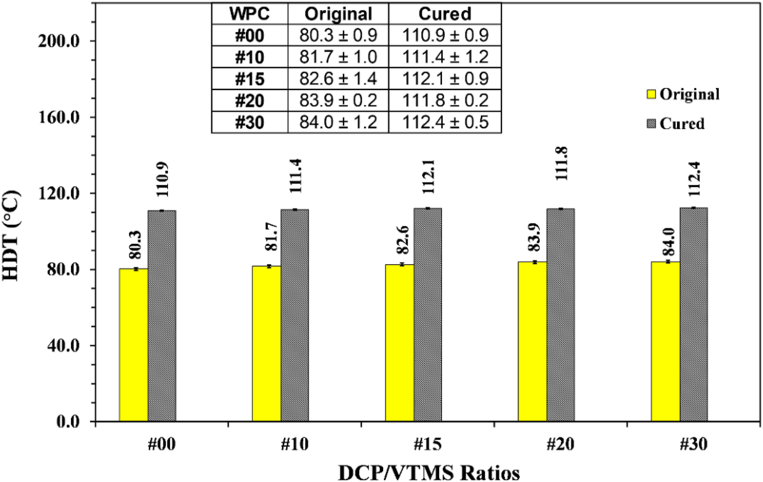
Notched and unnotched impact strengths of the macro crosslinked XWPC were measured on both original and cured samples. The test results were plotted against the DCP/VTMS ratios and shown in Figure 16. For the notched mode, it was seen that the impact strength was slowly reduced, on both original and cured samples, upon increasing the DCP/VTMS ratios. In comparison, it was obviously noticed that the original impact strength was greater than the cured one, regardless of the crosslinker ratio. With careful observation, the degree of reduction on notched impact strengths at the DCP/VTMS ratios from 0.20/0.020 to 0.30/0.030 were insignificant for both original and cured specimens. On the unnotched impact strength results, a similar trend to those notched mode was observed. In contrast, the unnotched strength of the cured XWPC was greater than the original one. Unnotched strength decreased from 5.75 to 5.18 and from 6.01 to 5.39 kJ/m2 for original and cured when crosslinker ratio was increased from 0.00/0.000 to 0.15/0.015, respectively. An insignificant change on both types of sample was noticed upon increasing the DCP/VTMS ratio from 0.15/0.015 to 0.30/0.030, progressively. A similar postulation stated in the HDT discussion must be adopted to explain these obtained impact strengths versus DCP/VTMS ratio correlation. Macro crosslink density and crosslinker dosing relationship must be the prime concerns. From the fact that the network density in the blended matrices was raised upon increasing the crosslinker dosing. Therefore, increasing in the brittleness of XWPC must be resulted. Then, reducing the impact strengths, both notched and unnotched, must be consequences. However, the thermoset characteristic of XWPC was delayed by the elastomeric amorphous PE chains formation at high DCP/VTMS dosing, from 0.20/0.020 to 0.30/0.030. With supplementing of the tough amorphous fraction, then the brittleness inferiority of XWPC must be retarded. (a) Notched and (b) unnotched impact strengths of the DCP/VTMS macro crosslinked XWPC, respectively.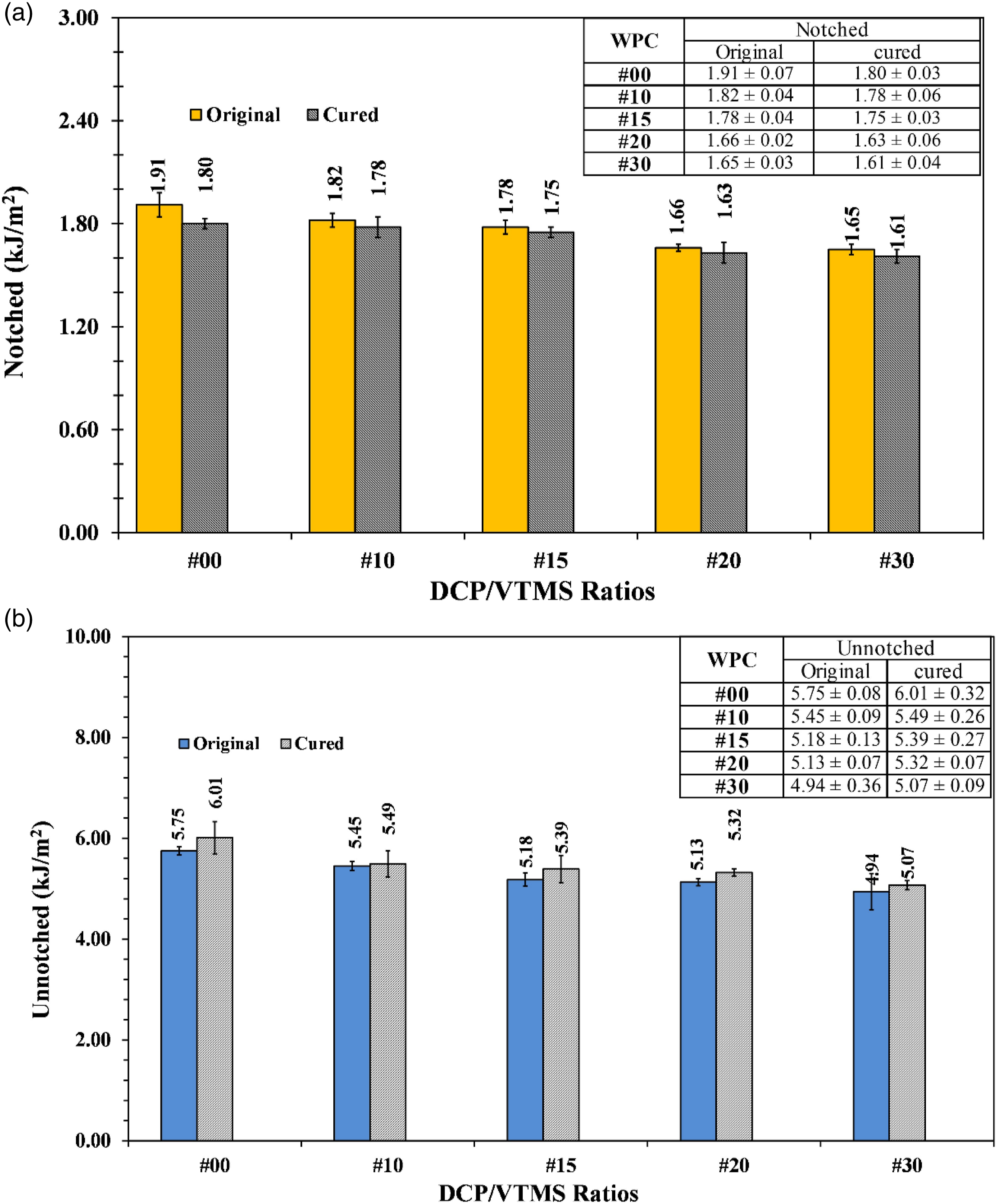
The rupture toughness of the macro crosslinked XWPC by means of three point bending flexural testing was conducted at the constant deformation rate of 15 mm/min. The flexural strength, modulus and deformation at break were recorded. Plots of the obtained test results versus DCP/VTMS ratios were performed and presented in Figure 17. Figure 17(a) shows that the flexural strength of the original XWPC was insignificantly changed with the DCP/VTMS ratio. Meanwhile, the strength measured from cured XWPC showed miniature increasing upon increasing the crosslinker ratio. However, from 0.15/0.015 to 0.30/0.030 ratios, the plateau trend on strength versus ratio was observed. Obviously, the strength of cured sample was greater than the original one, regardless of the crosslinker ratio. For the flexural modulus of both original and cured, as seen in Figure 17(b), were slowly climbed upon increasing DCP/VTMS ratio. Again, the plateau trend was observed from 0.20/0.020 to 0.30/0.030 ratios. At the given ratio, modulus of cured XWPC was clearly greater than the original sample. Figure 17(c) revealed that the deformation at break was found to be in the slow declining trend with the crosslinker ratio, for both original and cured XWPC. For all XWPC formulations, the deformation at break of cured XWPC was noticeably lower than the original one. The plateau area of the deformation was seemingly noticed from 0.15/0.015 to 0.30/0.030 ratios. Obeying the obtained flexural properties, the general interpretation by means the rupture toughness versus the DCP/VTMS ratios could pronounced. Insignificant change in flexural strength but increasing in the modulus and decreasing in the deformation at break upon increasing DCP/VTMS ratios were observed. These resulted flexure characteristics were commonly translated that the toughness of the manufactured macro crosslinked XWPCs was decreased upon increasing the crosslinker loading. As mentioned earlier, the thermoset characteristic of macro crosslinked chains, chain crystallinity and elastomeric amorphous PE chains formation must be all gathered for justification, especially on the cured XWPC results. Macro crosslinked density on the blended matrices caused by pre-mature atmospheric residual moisture reaction and by completed sauna incubation must be increased upon increasing the DCP/VTMS loading. Moreover, the network density of cured matrices was much higher than the original sample. Then, the brittleness thermoset property of cured XWPC must be dominated. In addition, the crystallinity of polymers chains must be increased upon prolonging sauna incubation and then vacuum drying of the cured XWPC at 90°C. This phenomenon must have an additional positive effect on the flexural strength of the wood composite material. Then, flexural strength and modulus of cured XWPC were greater than the original one. In contrast, the higher in crosslink density of macro crosslinked PE chains the greater in elastomeric amorphous chain fraction occurrence. Consequently, the progressive on the XWPC brittleness was delayed by this flexible amorphous constituent at high DCP/VTMS loading ratio. (a) Flexural strength, (b) modulus and (c) deformation at break of the DCP/VTMS macro crosslinked WPC, respectively.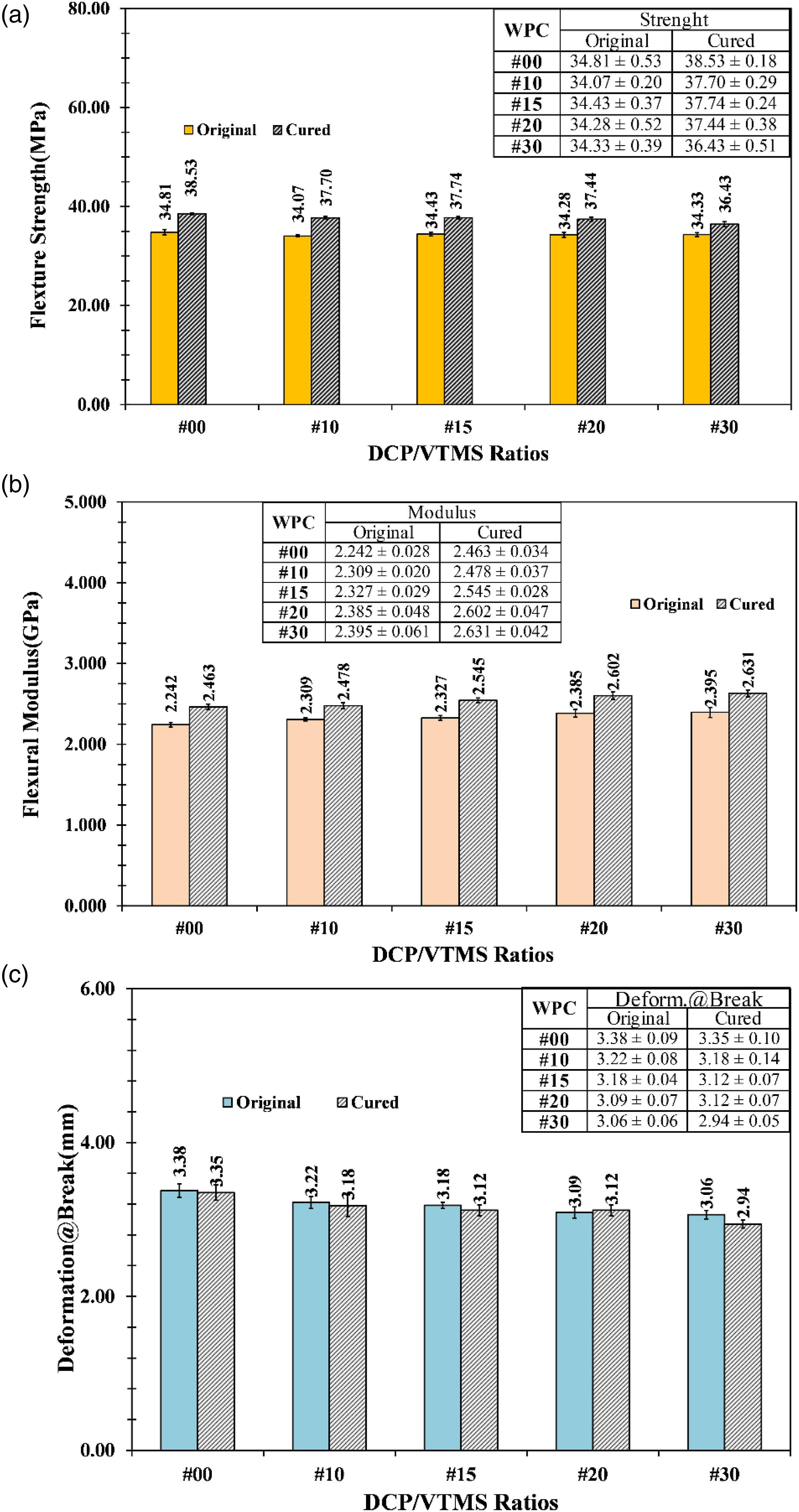
The tensile properties of the DCP/VTMS macro crosslinked XWPC by means of ultimate tensile strength, modulus and % elongation at break were measured at the strain rate of 50 mm/min. The obtained results versus crosslinker ratios were graphically presented in Figure 18. Obviously, the tensile strengths of both original and cured XWPC, shown in Figure 18(a), were gradually reduced when the DCP/VTMS ratios were increased from 0.00/0.000 to 0.15/0.015. Further increasing the ratio from 0.20/0.020 to 0.30/0.030, the magnitude of reduction became very tiny. Regardless of the DCP/VTMS ratio, the strength of cured XWPC was greater than the original sample. Insignificant change in tensile modulus for both types of XWPC sample versus the ratios were seen in Figure 18(b). However, the declining trend of the tensile modulus versus DCP/VTMS ratios could be biasedly proposed. At the given ratio, modulus of cured XWPC was apparently lower than the original one. For the % elongation at break, a similar trend to strength outcome was revealed. The obvious reduction in the % elongation at break for both cured and original XWPC were seen when the DCP/VTMS ratios were decreased from 0.00/0.000 to 0.15/0.015. After that, the degree of reduction became very small. For engineering material consideration, changing on the obtained tensile characteristics versus DCP/VTMS loading should be translated that the ductility of the manufactured XWPC was declined upon increasing the crosslinker loading. As stated in the impact and flexural properties rationalization, the higher in the crosslink density via high crosslinker loading the lower in tensile ductility or the greater in brittleness material. In comparison, the sauna incubated XWPC must have much greater macro network density than the untreated sample. Then, higher in tensile strength and modulus, but lower in % elongation at break must be experienced. Increasing in polymer chains crystallinity during prolonged sauna incubation and then vacuum drying had the exact trend and add-on effect on the tensile properties of the XWPC. In contrast, the rising in elastomeric amorphous PE chains occurrence upon increasing the macro crosslink density could retard the ductile inferiority of XWPC. Thus, the brittleness of the macro crosslinked XWPC must be conquered by those elastic chains formation. Consequently, the reduction in the XWPC ductility must be slowed down. Plots of (a) Ultimate tensile strengths, (b) modulus and (c) % elongation at break of the DCP/VTMS macro crosslinked XWPC, respectively.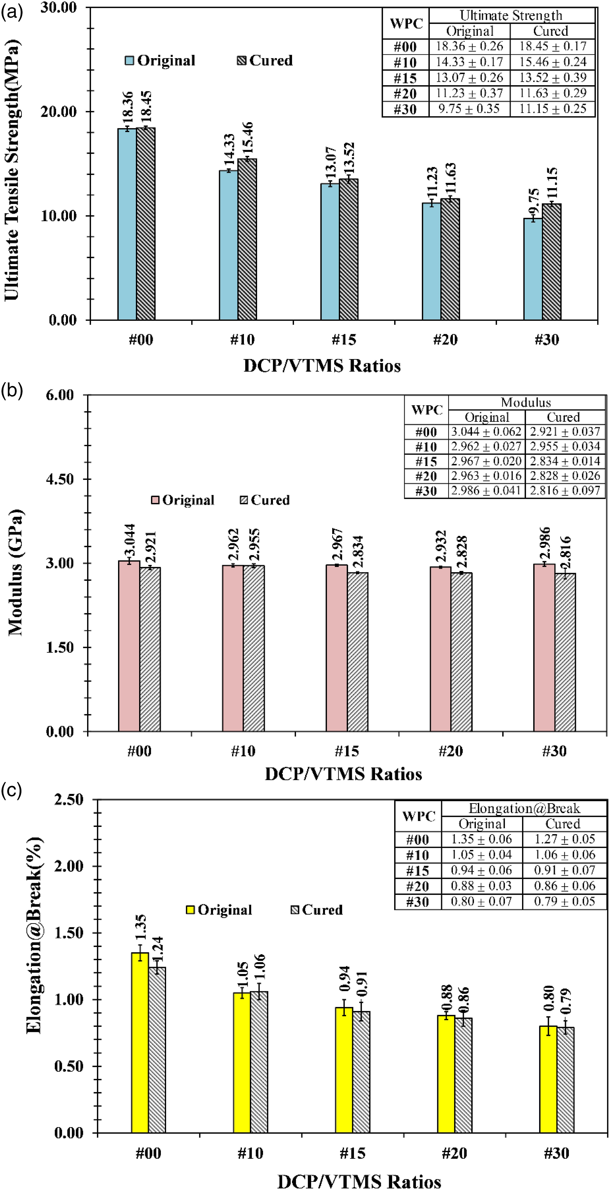
% water absorption and % dimensional swelling on XWPC after prolonged water submersion for 1- and 7-days were conducted. The test results were plotted against the DCP/VTMS ratios and shown in Figure 19(a) and (b), respectively. % water absorptions of XWPC on both original and cured samples after 1 day water submersion were noticeably increased, with very small magnitude, when the crosslinker ratios were increased. % absorption of cured XWPC was higher than the original one, at all given DCP/VTMS ratios. The exact trend was found for the 7-days immersion testing. Expectedly, results of 7-days immersion were obviously greater than the 1-day test. However, the magnitude of % absorptions on both immersion times were bare minimum. Much lower than 1% was recorded. The obtained test values were much lower than that was commonly found for natural wood cases. % Dimensional swelling of the manufactured macro crosslinked XWPC was almost unchanged upon increasing the DCP/VTMS ratios, for both original and cured samples, and both prolonged immersion periods. In comparison between original and cured samples, % swelling of the later sample was greater than the formal ones. The tiny degree of increasing on % water absorption against the crosslinker ratio could be justified by the chemical principle that VTMS has higher hydrophilicity than PE and rPET. Therefore, the water infusion capability on the manufactured XWPC must be raised upon increasing VTMS loading. On the sauna incubated DCP/VTMS macro crosslinked XWPC sample, the siloxane bonds (-Si-O-Si-) were formed as the crosslink bridges between the polymer chains, in the blended matrices, and also between RHF and polymer matrices (Zhou et al. 2009). High polarity of siloxane bonds could further enhance the hydrophilicity of cured XWPC. Consequently, the % water absorption of cured XWPC must be greater than the original one. % Dimensional swelling of the manufactured XWPC was a direct consequence from % water absorption. Great internal hydro static pressure must be attained at high % water absorption on XWPC sample. Then, an increase in % swelling should be experienced when % absorption was increased. However, the magnitude of % absorption and % swelling values for all XWPC formula were considerably very small, especially in comparison with other engineered and natural woods. It could be pronounced that the macro crosslinked XWPC manufactured from (rPET/LDPE)-g-MA, (HDPE/LDPE/UHMWPE)-g-MA and RHF with the presence of DCP/VTMS crosslinker showed particularly excellent durability property. (a) Water absorption, and (b) % swelling of the DCP/VTMS macro crosslinked WPC, respectively.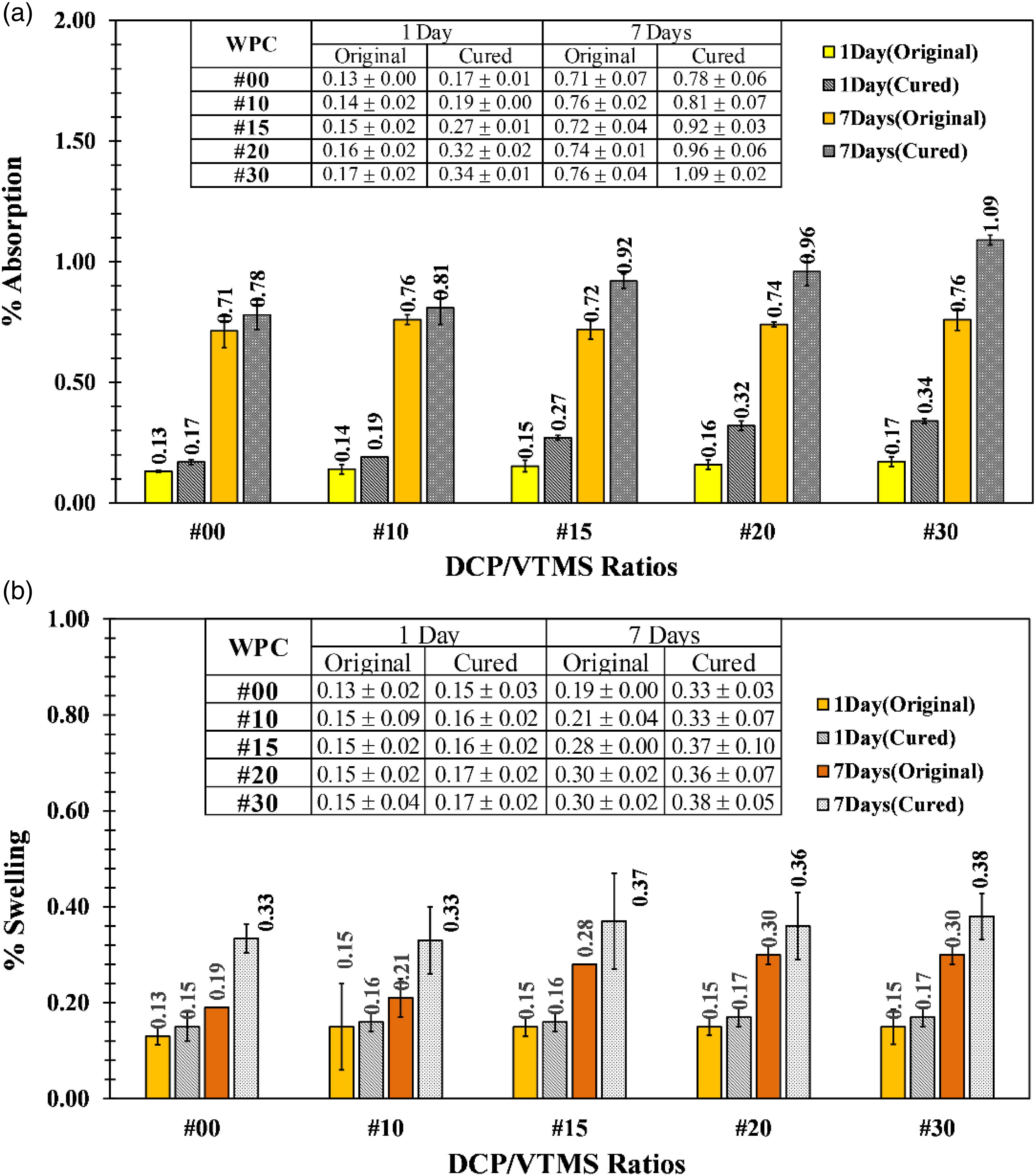
Conclusions
The RHF reinforcement showed a degradation temperature window in the range of 200–250°C. To prevent the thermal decomposition of RHF in the WPC manufacturing comprised of high melting point rPET and UHMWPE toughener polymers, the (rPET/LDPE)-g-MA and (HDPE/LDPE/UHMWPE)-g-MA blends were successfully prepared and used as the blended matrices. The sufficient flowability of the obtained blends at 240°C was verified by MFI. It was lower than the critical thermal decomposition temperature of RHF at 250°C. The presenting of MA grafted chains on the blends was confirmed by FTIR analysis. Absolute miscible blend was observed for the (HDPE/LDPE/UHMWPE)-g-MA. The acceptable compatibility between rPET and LDPE in the (rPET/LDPE)-g-MA blend was satisfied and verified by SEM. The WPC compounding temperature at below critical Td of RHF was accomplished. The effect of blend ratios in the blended matrices on the properties of manufactured WPC was testified. Interfacial improvement upon decreasing the (rPET/LDPE)-g-MA blend ratio was observed by SEM. High MA grafting efficiency on the (HDPE/LDPE/UHMWPE)-g-MA blend was justified and taken for explanation. The domain phase reversion between rPET and miscible PE polymers blend on the blended matrices was found at 50:50 blend ratio. The phase inversion ratio was one of the main critical factors that has a significant effect on the properties of the manufactured WPC. Typically, MFI and HDT were increased with decreasing (rPET/LDPE)-g-MA ratio from 90:10 to 50:50. Decreasing in MFI, but almost unchanged in HDT were found when further decreasing (rPET/LDPE)-g-MA ratio. For the mechanical performances, they were mostly reduced upon reducing the (rPET/LDPE)-g-MA portions to 50:50 ratio. Then, insignificant changes in the mechanical performances were occurred upon further decreasing the ratio to 10:90. The reduction of high strength rPET fraction was taken for justification on the mechanical performance deterioration. However, when the ratio exceeded the reversed phase composition, fiber/matrices interfacial enhancement and effectiveness of UHMWPE toughener were the add-on compensation for the mechanical properties weakening. % Water absorption and % swelling of the WPC were reduced due to the declining of hydrophilic rPET composition in the blended matrices. The macro crosslinked XWPC using DCP/VTMS as crosslinker system was explored. The SEM analysis revealed the elastomeric bridges formation on the sauna cured samples. The MFI values of both original and cured XWPC samples were reduced by increasing the crosslinker ratios. MFI of cured XWPC was decreased with increasing DCP/VTMS ratio. Rising in macro crosslink density was taken for explanation. There was an insignificant effect of DCP/VTMS ratios on the HDT of the manufactured XWPC. Small enhancement of HDT was mainly caused by the macro network density. The toughness and ductility characteristics by mean of impact strengths, flexural and tensile characteristics were found to be decreased upon increasing the crosslinker loading. High macro crosslink density at high DCP/VTMS dosing was taken for explanation. However, rising in the flexible fraction of the elastomeric amorphous PE chains at high crosslinker dosing retarded the brittleness advancement of the macro crosslinked XWPC. The durability by means of % water absorption and % swelling was found to be insignificantly changing with the DCP/VTMS ratios. However, a very tiny increasing trend upon rising in the ratio was observed. Hydrophilicity of the grafted silane and the siloxane bonding formation was a prime suspect.
Footnotes
Acknowledgements
This work was financially supported by the Suranaree University of Technology.
Declaration of conflicting interests
The author(s) declared no potential conflicts of interest with respect to the research, authorship, and/or publication of this article.
Funding
The author(s) received no financial support for the research, authorship, and/or publication of this article.