
Abstract
The main purpose of this study is to investigate usability of resistance welding joining method for poly (aryletherketone) (PAEK) thermoplastic matrix/carbon fiber (CF) reinforced composite laminates (PAEK/CF). For this purpose, effects of six different Interlayer Forms having different stainless steel meshes as Heating Elements and different woven glass fiber forms as Insulating Layers were studied. After determining welding parameters for each specimen group, performance of the resistance welding operations was compared by ultrasonic inspection, microscopic examination, DSC analyses, and by three different interlaminar mechanical tests. Analyses and tests generally revealed that use of stainless steel meshes as Heating Elements could supply proper amperage level for the heating, melting and crystallization stages of the PAEK matrix during welding consolidation. Depending on the lay-up configuration of Interlayer Forms, “amperage levels” determined for the heating, melting dwell and crystallization dwell were in the ranges of 46–100 A, 40–90 A and 25–50 A, respectively, It was also observed that in order to prevent Current Leakage problem to the other layers in the composite laminate, rather thicker and heavier woven glass fiber forms as Insulating Layers should be used. Otherwise, not only voids could form in the thermoplastic matrix, but also delamination might occur in the upper or lower PAEK/CF composite laminates being welded. When thicker and heavier insulating layer was used; interlaminar mechanical properties of Single Lap Shear Strength, Fracture Toughness under Mode-I and Mode-II were determined as high as 36.77 MPa, 3.76 kJ/m2 and 4.71 kJ/m2, respectively.
Keywords
Introduction
Although many engineering thermoplastics could be used as the matrix material for a variety of applications, aerospace industry especially prefers higher mechanical performance, higher temperature resistant, semi-crystalline engineering thermoplastics such as poly (etheretherketone) (PEEK), poly (etherketoneketone) (PEKK), poly (aryletherketone), (PAEK) and poly (phenylenesulfide) (PPS). Due to their semi-crystalline structure and aromatic groups present in their monomers, it is possible to use them even above their glass transition temperatures. In this study, thermoplastic composite laminates to be welded has PAEK matrix.
Although there are well established mechanical fastening and adhesive bonding techniques for the traditional thermoset matrix composite structures, they are not generally preferred to be used in the continuous fiber reinforced thermoplastic composite structures. In aerospace industry, the most common four methods utilized to join thermoplastic matrix composite structures are co-consolidation, induction welding, ultrasonic welding and resistance welding.
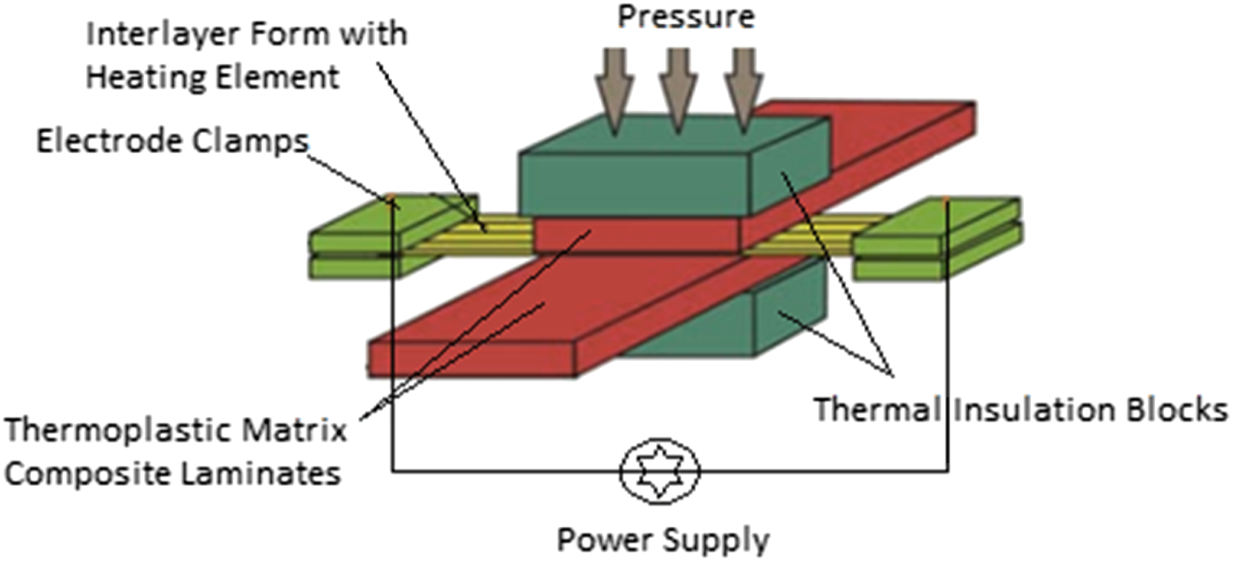
The resistance welding process basically includes placing an interlayer form having conductive heating element between the composite laminates to be welded. Electrical current generated by power supply unit is circulated across the weld-line to rise the temperature at the interface. Figure 1 shows a typical laboratory-scale resistance welding set-up indicating main parts of the system.
1
Power unit as the voltage supplier can deliver either direct or alternating current as both are applicable and feasible in the welding process. The function of the thermal insulation blocks in the resistance welding system is to avoid temperature outflow causing heat loss in the system while electrode clamps made of metals with excellent conductivity are used to obtain maximum conductance in the heating element for consistent weld-line. Before the start of welding operation, thermocouples are used to monitor the level and distribution of the temperature in the welding zone. Typical laboratory-scale resistance welding set-up.
1
Resistance welding technique could be used for joining of various thermoplastic matrix composite laminates. One of the most significant pieces in resistance welding operations is the “Interlayer Form” placed in between the two composite parts to be joined (Figure 2). The main layer located in the center of this form is named as conductive “Heating Element”. When power supply unit gives electric current to the heating element, it melts the surrounding thermoplastic matrix of the composite laminates. Heating element cannot be taken out from the interface, it remains within the composite joint. Typical structure and composition of the interlayer form having (i) heating element, (ii) neat thermoplastic film, (iii) insulating layer.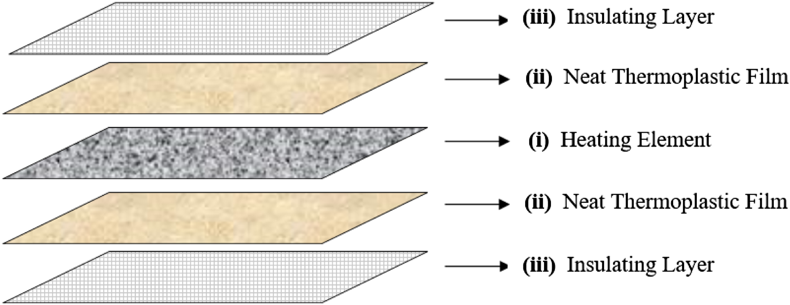
Although there are other non-metallic materials such as different carbon fiber forms impregnated with different neat polymer films and nanocomposites with MWCNT; the most widely used heating element in the industry is the various forms of “stainless steel meshes” since they generally provide a uniform current distribution across the weld besides from other parameters affecting uniformity of the current distribution such as edge effects etc. Uniform current distribution prevents possible anomalies in the temperature profiles and formation of flaws in the weld. In this study, use of two different stainless-steel mesh forms is investigated.
Interlayer forms might have only heating element layers; on the other hand, to achieve higher performance in resistance welding operations, interlayer forms might also include two more very thin layers located above and below the heating element central layer as shown in Figure 2. The function of the “Neat Thermoplastic Film” is to increase the resin content in between the heating element and insulating layer for a better joining performance. It is usually chosen as the thin film layer made of the same thermoplastic matrix used in the composite laminates to be welded. Thus, in this study, thin films of PAEK were used.
The function of the “Insulating Layer” is to insulate other layers of the laminate from the welding current so that they might be kept away from any thermal damages. This layer used in the industry is usually woven forms of Glass Fibers (GF) impregnated with the same thermoplastic matrix as the laminates. Thus, in this study, effects of three insulating layers having PAEK impregnated three different woven GF forms were evaluated.
Consolidation is one of the most crucial step during all manufacturing processes of continuous fiber reinforced thermoplastic matrix composite parts. It is simply hot pressing of matrix and fiber layers or their prepregs to achieve proper interlayer adhesion and to get a consistent thickness for the composite laminate structure. Of course, for the semi-crystalline thermoplastic matrices, proper cooling parameters are also required in order to achieve higher degree of matrix crystallinity. Therefore, “consolidation” is also significant during resistance welding operation. There are four main process parameters of resistance welding process; power level, pressure level, melting dwell time and crystallization dwell time, influencing the consolidation level and degree of crystallinity of the thermoplastic matrix of the composite parts to be welded.
In the last two decades, use of high temperature resistant thermoplastic matrices reinforced with high mechanical performance continuous fibers are increasing especially in aerospace industry such as aircrafts, UAVs, helicopters, drones, satellites, etc. Therefore, use of resistance welding process for joining of the components in these structures became inevitable. Common examples for the resistance welded parts are stiffeners, ribs, spars, wedges; and stringers to primary load carrier parts such as composite skins of fuselages, spoilers, landing doors, ailerons, etc.
Literature review revealed that although there are extensive number of studies2–21 on the ultrasonic welding and induction welding, the number of the studies on resistance welding are rather limited;22–32 being especially on the heat transfer modelling of parameters and effects of interlayer form, as summarized below.
Ageorges et al. 22 used both thermal imaging and three-dimensional heat transfer modelling to determine the process parameters for welding of carbon fiber reinforced PEI composite laminates. As the heating element of the process, unidirectional and woven carbon fiber forms, while for the insulating layer glass fiber forms impregnated with PEI were used. Joining performance of the interface was evaluated by applying lap shear strength and double-cantilever beam tests. As a result of the study, it is found that the temperature distribution through the woven heating element was more homogenous, and the temperature distribution predictions obtained via finite-element model was slightly higher than the recorded values during the welding operations.
In the study of Xiao et al., 23 thermal analysis by two-dimensional finite element modelling was used to select the process parameters for welding of carbon fiber reinforced PEEK composite laminates. Heating element selected was also carbon fiber forms. Evaluations on the mechanical performance of the joint was made by applying single lap shear strength tests and examining the microstructure of the weld-line. They indicated that when the optimum parameters determined were used, 34 MPa lap shear strength could be obtained.
Jakobsen et al. 24 conducted a study on transient two-dimensional thermal model for resistance welding of carbon fiber reinforced PEEK composite laminates to determine the optimum processing parameters. A single layer of unidirectional carbon fiber form was used as the heating element along with two neat PEEK films wrapping the heating element to avoid current leakage from the interface. Double cantilever beam specimens were tested to evaluate the mechanical performance of the joints in terms of Mode-I fracture toughness values. They revealed that when the optimum welding parameters determined by the model were used; fracture toughness value of the welded laminate (2 kJ/m2) would be almost the same obtained from the compression molded (without welding) laminate, i.e. almost 100% match.
Colak et al. 25 investigated the resistance welding of carbon fiber reinforced PEEK composite laminates with varying thicknesses by using one-dimensional transient heat transfer model, degradation kinetics model and bonding model. Heating element used in the models were also carbon fiber forms. They indicated that the optimum process parameters for welding of the laminates with varying thicknesses could be obtained to minimize processing time significantly without sacrificing the quality requirements such as degree of crystallinity of the PEEK matrix.
Holmes and Gillespie 26 conducted a parametric study on the usability of resistance welding for very large-scale joints of carbon fiber reinforced PEEK composite structures by using certain thermal analysis based on carbon fiber heating element forms. They indicated that process parameters especially power level could be modeled via a three-dimensional analysis to achieve sequential resistance welding of the large-scale components.
Hou and Friedrich 27 investigated effects of using carbon fiber forms as the heating element layer during resistance welding of PPS/CF composite laminates. Weld-line quality was assessed by applying lap shear strength and double cantilever beam tests. The morphology and microstructure of the contact surfaces were also analyzed by using scanning electron microscopy (SEM). They indicated that sufficient level of weld quality could be obtained within the power range of 40 to 140 kWm−2. It was also observed that the intralaminar fracture toughness values were found equivalent to the ones obtained from compression molded specimens.
Hou et al. 28 conducted a study regarding the resistance welding of carbon fiber reinforced PEI composite laminates. They used steel meshes as the heating element to achieve uniform temperature distribution at the interface. They also used glass fiber forms impregnated with PEI to insulate the surfaces of the composite laminates from electrical current leakage. Welding parameters such as power level, welding time and pressure were optimized by using the results of microstructure analysis and mechanical tests of lap-shear strength and Mode-I fracture toughness. They revealed that power level (kW/m2) plays a very significant role in the mechanical performance of the joints.
Howie et al. 29 investigated optimum parameters for the resistance welding of carbon fiber reinforced polyarylsulfone/polysulfone dual-polymer matrix composite laminates. A single layer of carbon fiber form was used as the heating element, and both surfaces were impregnated with neat polysulfone to increase the contact performance. Ultrasonic images and photomicrographs were used to observe the weld line, and their performance were compared with lap shear strength tests. They concluded that the bond line thickness is mainly a function of pressure and temperature rather than the welding time.
Optimum welding process parameters for carbon fiber reinforced PEEK composite laminates were also studied by Don et al. 30 A single layer of unidirectional carbon fiber form was used as the heating element impregnated with neat PEEK and PEI films. In order to assess different configurations of composite laminates having unidirectional and quasi-isotropic lay-up, lap shear strength and Mode-I fracture toughness tests were conducted. Shear strength results (10–30 MPa) and fracture toughness results (0.41–1.34 kJ/m2) were evaluated with respect to the power level, pressure level and laminate lay-up sequence; concluding that welding performance was very promising compared to the compression molded laminates without welding.
Brassard et al. 31 proposed an alternative heating element as 10 wt.% multi-walled carbon nanotube (MWCNT) mixed into PEI matrix to be used in the resistance welding of PEEK/CF composite laminates. In order to evaluate mechanical performance of the joints, single lap shear strength tests were conducted. It was observed that due to the deficiency of uniform distribution of nanoparticles in the matrix; a non-uniform heating occurred at the weld area, resulting in rather a low shear strength of 19.6 MPa with a cohesive failure within the heating element layer. They concluded that nanocomposite approach for the heating element layer need further investigations in terms of uniform nanoparticle distribution.
Brassard et al. 32 also introduced a 3D transient finite element model of the resistance welding process performed by using MWCNT reinforced PEI matrix nanocomposite heating element to join the CF/PEEK composite laminates. Simulations were conducted to obtain the uniform temperature distribution across the weld line, and the fracture mechanisms along with the types were investigated via SEM. As the ultimate conclusion of the study, welding performance of LSS specimens were improved up to 28% by using the optimized processing window for the materials to be joined.
Literature survey discussed above revealed that although there are certain number of resistance welding studies on the Carbon Fiber (CF) reinforced composite laminates having thermoplastic matrices of PEEK, PEI and PPS; no studies were reported on the poly (aryletherketone) (PAEK) matrix.
Therefore, the main purpose of this study is, as the first time in the literature, to investigate the usability of resistance welding joining method for PAEK/CF thermoplastic composite laminates.
For this purpose, six different “Interlayer Forms” comprised of two different stainless steel meshes as “Heating Elements” and three different glass fiber reinforced PAEK forms as “Insulating Layers” were investigated. After having the optimum welding parameters determined for each interlayer form configuration, joint performance of the resistance welding operations was compared by ultrasonic inspection, microscopic examination, DSC analyses, and by three different interlaminar mechanical tests.
Experimental work
Experimental procedures used in this study could be grouped into four main steps; (i) preparation of the thermoplastic matrix composite laminates to be welded, (ii) production of the six different interlayer form configurations, (iii) resistance welding operations, and (iv) testing and analyses for the evaluation of the weld performance.
PAEK/CF thermoplastic composite laminates to be welded
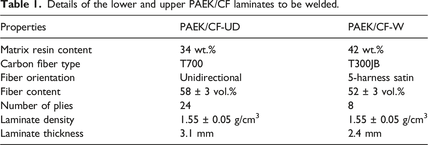
Details of the lower and upper PAEK/CF laminates to be welded.
Preliminary analyses conducted for the PAEK/CF laminates
In order to verify certain properties of the PAEK/CF laminates given by the supplier, three analyses were conducted; the first one was Fiber Volume Content determination while the others were Microstructural and Thermal Analyses.
Fiber volume content analysis
It is known that amount of the reinforcing fibers in the composite laminates is the most crucial parameter in improving all mechanical and other properties. Therefore, in this study, ASTM D3171 standard was used to determine the fiber content of the PAEK/CF laminates with sulfuric acid and hydrogen peroxide solution digestion method by using the Procedure B in the standard. First, specimens were weighted using a precision balance before holding them in the acid solution until no PAEK matrix was left. The remaining carbon fibers were washed, dried, and weighted precisely to determine their weight percentage values. Eight specimens were tested in total, with the dimensions of 20 mm × 10 mm having 3.1 mm and 2.4 mm thickness values.
Microstructural analysis
In order to examine possible interfacial defects including porosity and fiber distortion in the PAEK/CF laminates, microstructural analyses were conducted by using Olympus GX53 optic microscope system with an image analysis software. At least three measurements were conducted for each condition.
It should be noted that microstructural analyses were conducted also after the welding operations in order to reveal possible microstructural changes, especially the degree of deviations in the thickness of the welded laminates.
Differential scanning calorimetry analysis
Differential scanning calorimetry (DSC) (TA Instruments, Q100) analyses were carried out to determine the glass transition temperature (Tg) and enthalpies of melting and cold crystallization of the PAEK matrix of the laminates under first heating profile from room temperature to 350°C at a rate of 10°C/min under nitrogen flow. At least three measurements, using around 20 mg samples, were conducted for each condition. Degree of crystallinity of PAEK matrix was calculated after the enthalpies were determined.
Apart from the Tg and
Production of six different interlayer forms
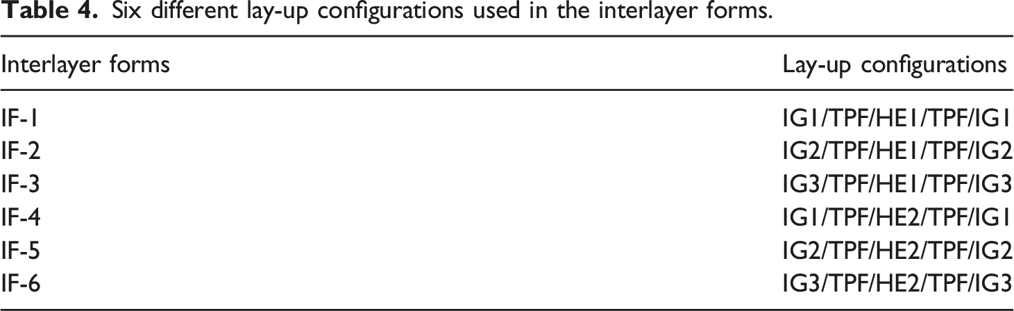
As shown in Figure 2, interlayer forms used are comprised of three sublayers; (i) heating element, (ii) neat thermoplastic film and (iii) insulating layer. In this study, effects of Interlayer Form (IF) on the performance of resistance welding were investigated by constructing six different configurations. For this purpose, as the heating element layer two different stainless steel (SS) mesh forms are used; while for the insulating layer three different woven glass fiber (GF) forms impregnated with the matrix resin are used. As the neat thermoplastic film, only one type of the neat PAEK film was used. Details of these layers are summarized below.
Heating element
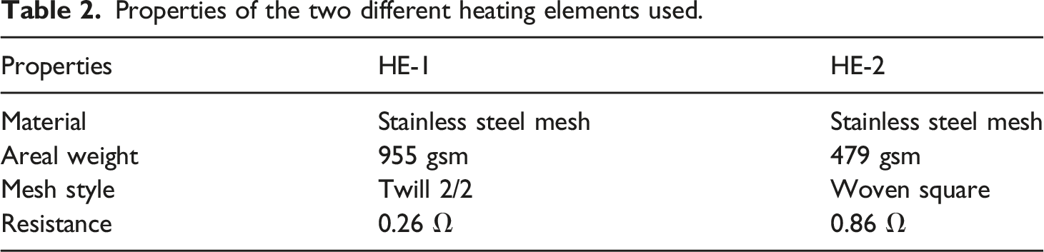
Properties of the two different heating elements used.
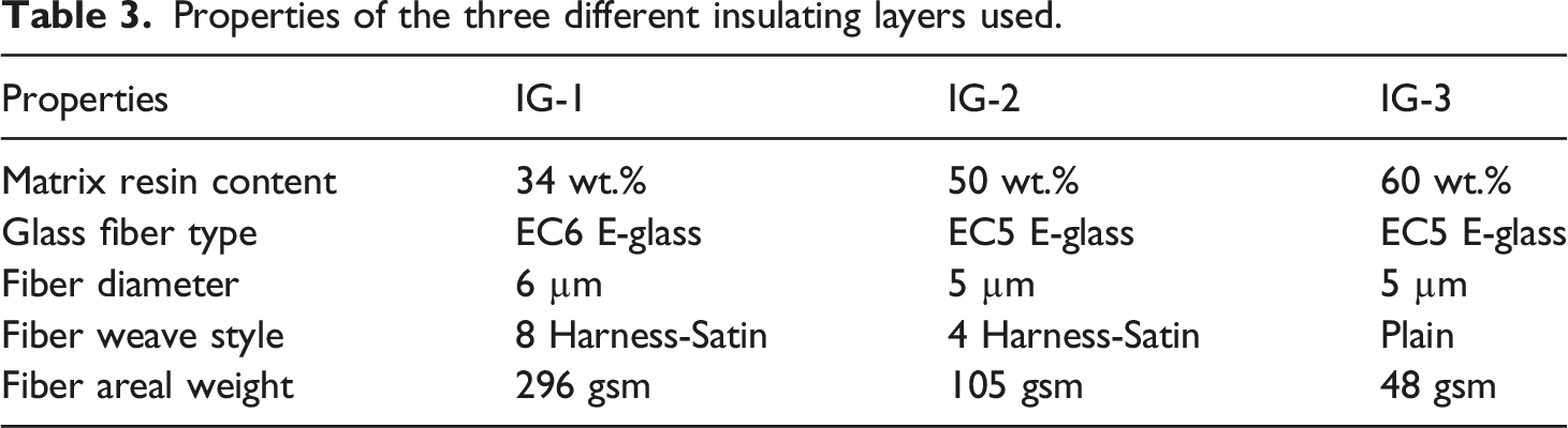
Insulating layer
Properties of the three different insulating layers used.
Neat thermoplastic film
The same thermoplastic type (PAEK) with the matrices of the composite laminates was used as the neat thermoplastic film (TPF) with a thickness of 60 μm. Its function was to increase the matrix resin content at the interface between the insulating layers and heating elements.
Six different lay-up configurations used in the interlayer forms.
Consolidation of the interlayer forms
Before welding operations, these interlayer forms having many sub-layers should be converted into “one piece” form, i.e. a kind of “consolidation” process would be necessary. As shown in Figure 3(a), six different lay-up configurations were constructed on a tool in the form of large plates. Then, these plates were covered with a high temperature resistant plastic bag (Figure 3(b)) for autoclave consolidation (Figure 3(c)). Steps during consolidation of the interlayer forms; (a) a plate of IF lay-up’s on a tool, (b) plastic bagging of the IF plate, (c) consolidation in the autoclave, (d) IF plates after consolidation, (e) IF plate after demolding, and (f) IF strips after cutting.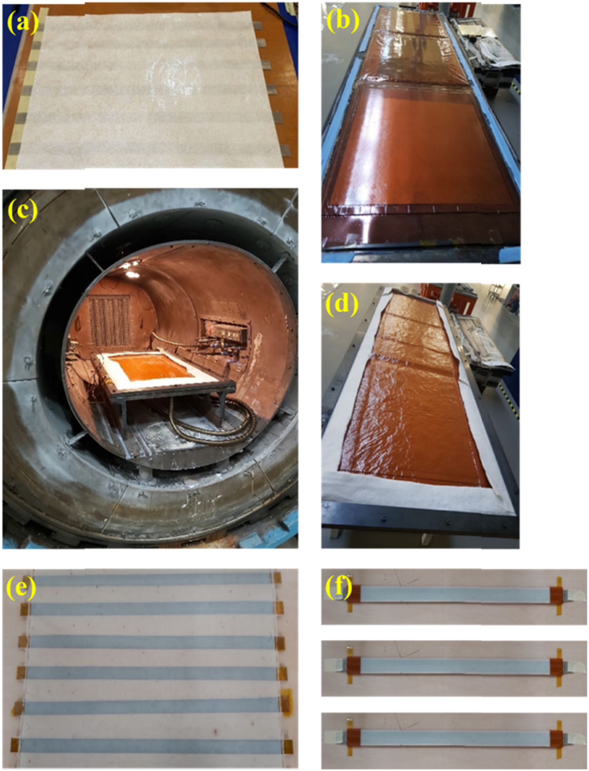
In the autoclave, vacuum bagging (−450 to −650 mmHg) was applied with the consolidation temperature of 370°C, pressure of 8 bar, and a dwell time of 30 min to obtain uniform melting of the polymer layers. Then, these large plates of interlayer forms were cooled slowly (4°C/min) so that there would be sufficient time for the crystallization of the polymer layers.
When the autoclave consolidation was over, plates of interlayer forms were ready for demolding (Figure 3(d)). Figure 3(e) shows plates of consolidated interlayer form while Figure 3(f) indicates individual interlayer forms after cutting into strips. These strips of interlayer forms would be placed in between the lower and upper composite laminate strips during welding operations.
Resistance welding operations
It is known that, as shown in Figure 4, during resistance welding operations of thermoplastic composite laminates under constant pressure, four thermal stages are required: Heating, Consolidation Melting, Crystallization, Cooling. Thus, for an efficient resistance welding operation, determination of the welding parameters; pressure level, power level, heating and cooling rate, dwell times of consolidation melting and matrix crystallization are crucial. Typical temperature—time profile during four thermal stages required in resistance welding of the thermoplastic matrix composite laminates. Note that, values given in the axes are typical ranges for the PAEK matrix.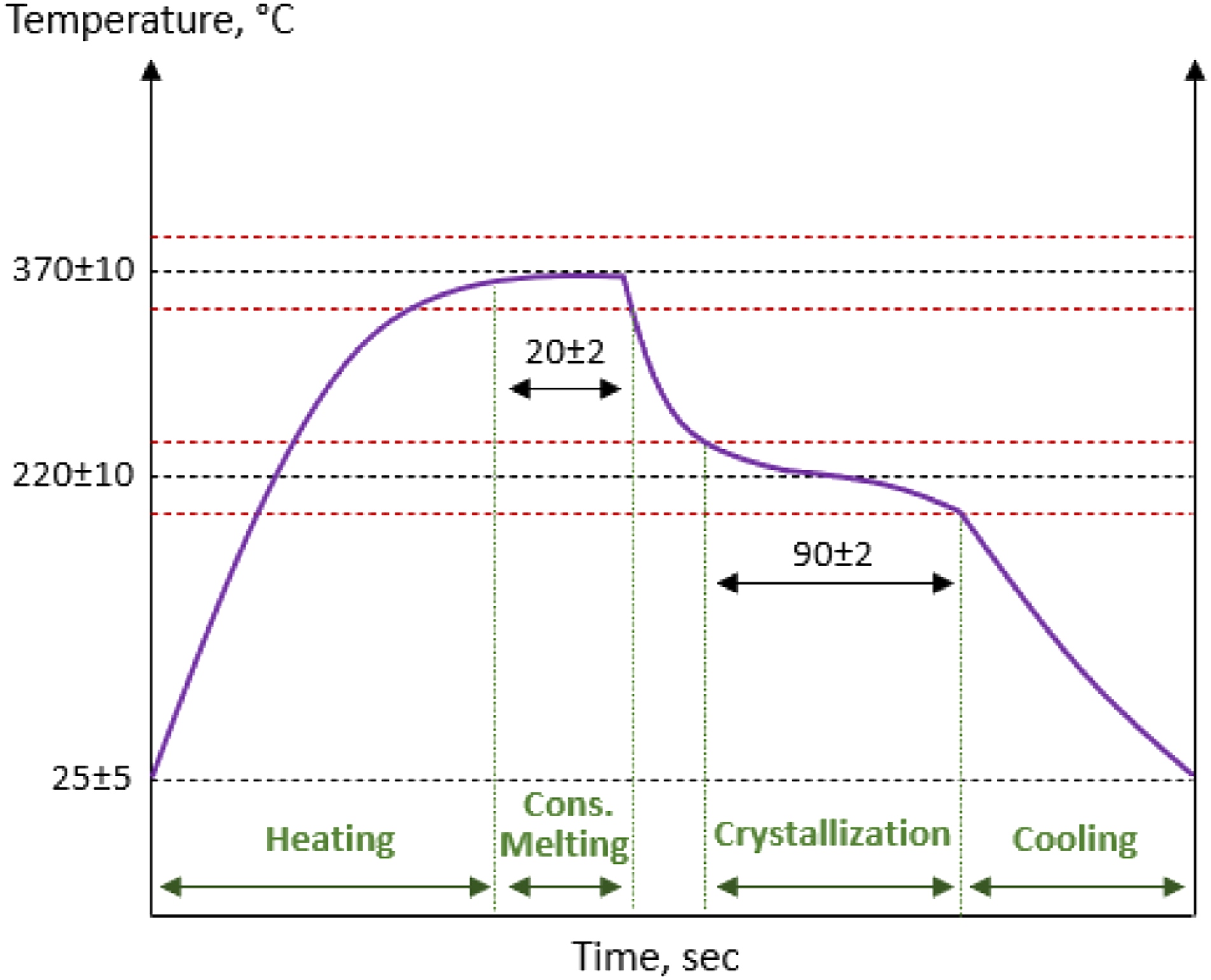
Therefore, for each six different interlayer forms, before starting resistance welding operations; several thermal studies were conducted to determine the optimum parameters of power level (voltage and amperage), heating and cooling rates, consolidation melting and crystallization dwell times, etc. The applied pressure was kept constant around 6 bars while the other consolidation parameter ranges required for melting and crystallization of the PAEK matrix were indicated in the time-temperature axes of Figure 4.
It should be noted that details of these preliminary thermal studies together with the optimum resistance welding parameters obtained for each configuration will be given in the results and discussion section. After determining the optimum parameters, resistance welding operations of the lower and upper PAEK/CF laminates with six different interlayer forms were conducted by using the welding system.
Ultrasonic inspection and machining of the welded specimens
After welding operations, all specimen groups were inspected for the possibilities of void formation and delamination. For this purpose, Automated Ultrasonic Through Transmission (AUTT) inspection technique was used via Tenotomy Taurus Twin 2.0 system operated by properly qualified personnel. After examining the images of C-Scan maps obtained, certain suspicious regions were verified by using the Manual Ultrasonic Pulse Echo (MUPE) technique via Olympus Omniscan SX system. Then, in accordance with the related standards, mechanical testing specimens were machined by using 5-axis CNC system (CMS Advanced Materials Technology).
Mechanical testing of the welded specimens
In order to evaluate welding performance of the specimens having six different interlayer form configurations, mechanical tests were conducted to determine their “Interlaminar Fracture Toughness” and “Interlaminar Shear Strength” properties in accordance with the testing standards used for aerospace structures. Tests were conducted at laboratory conditions by using 250 kN capacity Instron Universal Testing system. For each specimen group four specimens were tested, and the properties were reported as average values with ± standard deviation.
Mode-I interlaminar fracture toughness energy (GIC) tests
This test was conducted in accordance with the EN 6033 standard. The edge initial crack necessary was introduced by inserting a release film into the interface before the welding operations. After obtaining the “Load versus Displacement” curve when a total of 100 mm propagated crack length was reached, G IC Fracture Toughness values were calculated.
Mode-II interlaminar fracture toughness energy (GIIC) tests
This test was conducted in accordance with the EN 6034 standard. The edge initial crack necessary was introduced by inserting a release film into the interface before the welding operations. During the test, “Load versus Displacement” curves were recorded until a sudden load drop was observed, which represents the start of failure in the weld interface. At this point, G IIC Fracture Toughness values were calculated.
Single lap shear strength tests
This test was conducted in accordance with ASTM D5868 standard. Lap-shear regions, i.e. weld area of 25 × 12.5 mm, between the laminates were obtained by machining slots to the upper and lower welded laminates. During the test, “Load versus Displacement” curves were recorded until the interlaminar shear failure occurred in the weld interface. Then, Single Lap Shear Strength (SLSS) values were calculated.
Results and discussions
In this study, before welding operations, certain preliminary analyses were conducted to verify basic data on the upper and lower PAEK/CF laminates given by the supplier. Then, thermal profile studies were carried out to determine the welding parameters to be used for each interlayer form configurations. After welding, laminate strips were inspected by an ultrasonic non-destructive technique. In order to investigate effects of six different interlayer form configurations on the welding performance of the specimens, three different interlaminar tests were conducted. After mechanical tests, failure mode observations, microscopic examination and thermal analysis were also performed. Results of these experimental steps are discussed in the following sections.
Preliminary analyses of the PAEK/CF laminates
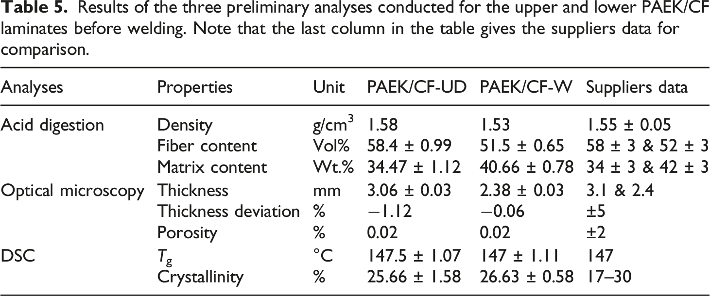
Results of the three preliminary analyses conducted for the upper and lower PAEK/CF laminates before welding. Note that the last column in the table gives the suppliers data for comparison.
Fiber and matrix content determination by acid digestion method
Contents of the fiber and matrix phases are very important key characteristics for composite materials; since the reinforcement (fiber) phase is the main load carrier allowing the composite material to endure against mechanical loads and stresses, while the matrix is the other crucial phase to transfer the applied loads to the strong reinforcements.
In this study, fiber and matrix content of the PAEK/CF laminates to be welded were determined by conducting acid digestion method. At least three measurements were carried out for both upper and lower laminates in accordance with the procedure given in the experimental part. Average values of the fiber and matrix contents together with densities are tabulated in Table 5. It was seen that density of the lower and upper laminates were 1.58 and 1.53 g/cm3; while their fiber contents were 58.5 and 51.5 vol.%, and their matrix contents were 34.5 and 40.6 wt.%, respectively. All the values determined were consistent with the suppliers data.
Thickness and porosity determination by optical microscopy
Before starting welding operations, it was also important to verify given thicknesses of the upper and lower PAEK/CF laminates including the possible microstructural defects such as porosity. Therefore, upper and lower laminates used in this study were first inspected by using an optical microscope with an image analyses software to observe porosity and to measure the thicknesses of the laminates precisely.
At least three examinations and measurements were conducted for the upper and lower laminates, and the calculations were done as explained in the experimental part. Figure 5 shows an example of the through-thickness optical microscope image analyses for precise thickness measurements and porosity determination for the upper and lower laminates. Note that thickness measurements were done at least from three different locations of the cross-sectional views of the laminate thicknesses. Example of the through-thickness optical microscope image analysis for the upper and lower PAEK/CF laminates.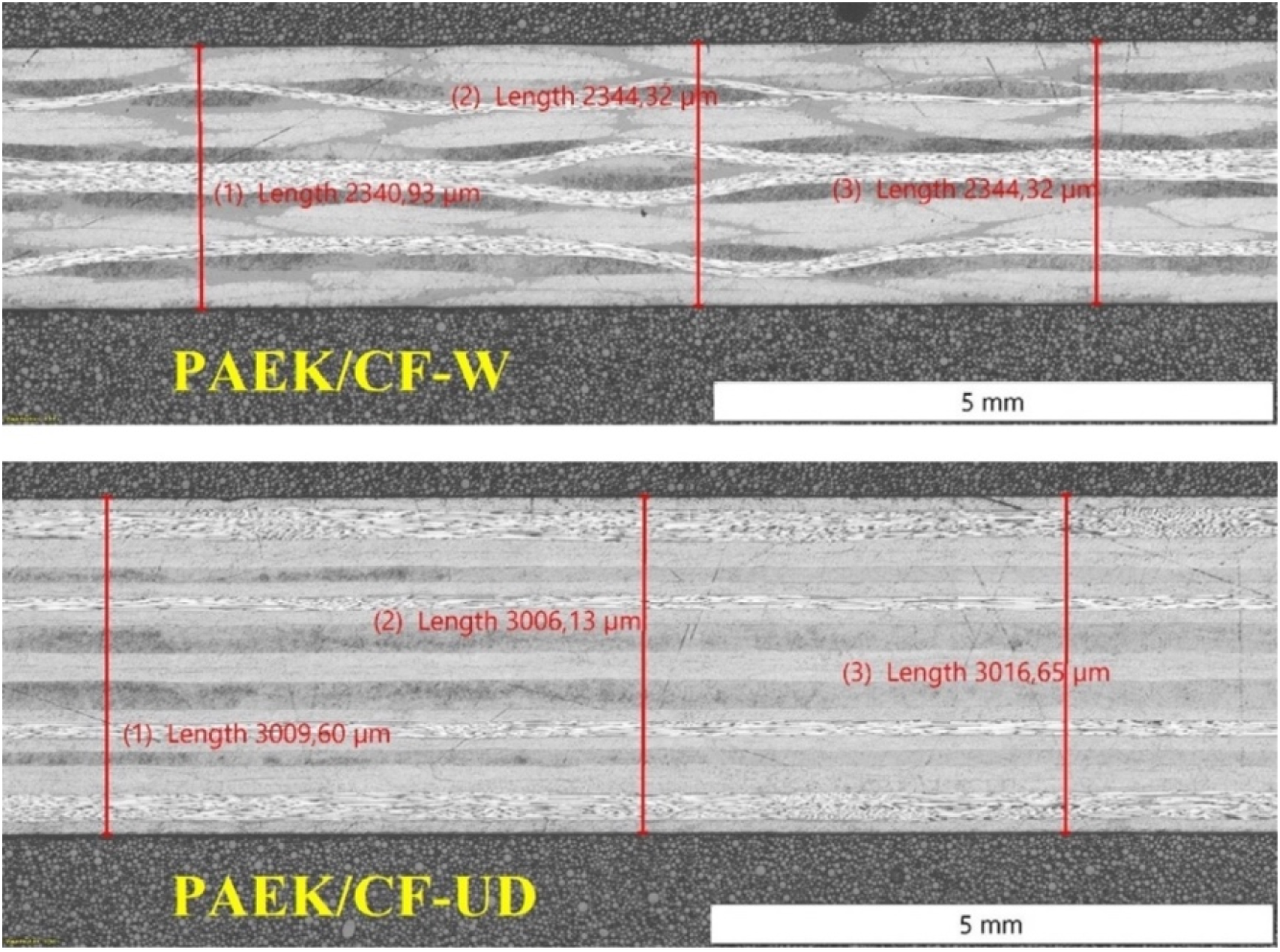
Table 5 indicated that the precise thickness of the lower laminate was 3.06 mm with a thickness deviation of −1.12%; while these values for the upper laminate were 2.38 mm and −0.06%, respectively. Porosity level determined with the image analysis software for each laminate were only 0.02%. These measurements were again consistent with the suppliers data.
Glass transition and crystallinity determination by DSC analyses
In order to assess Glass Transition Temperature (Tg) and Crystallinity ( Example of the first heating DSC thermograms for the upper and lower PAEK/CF laminates.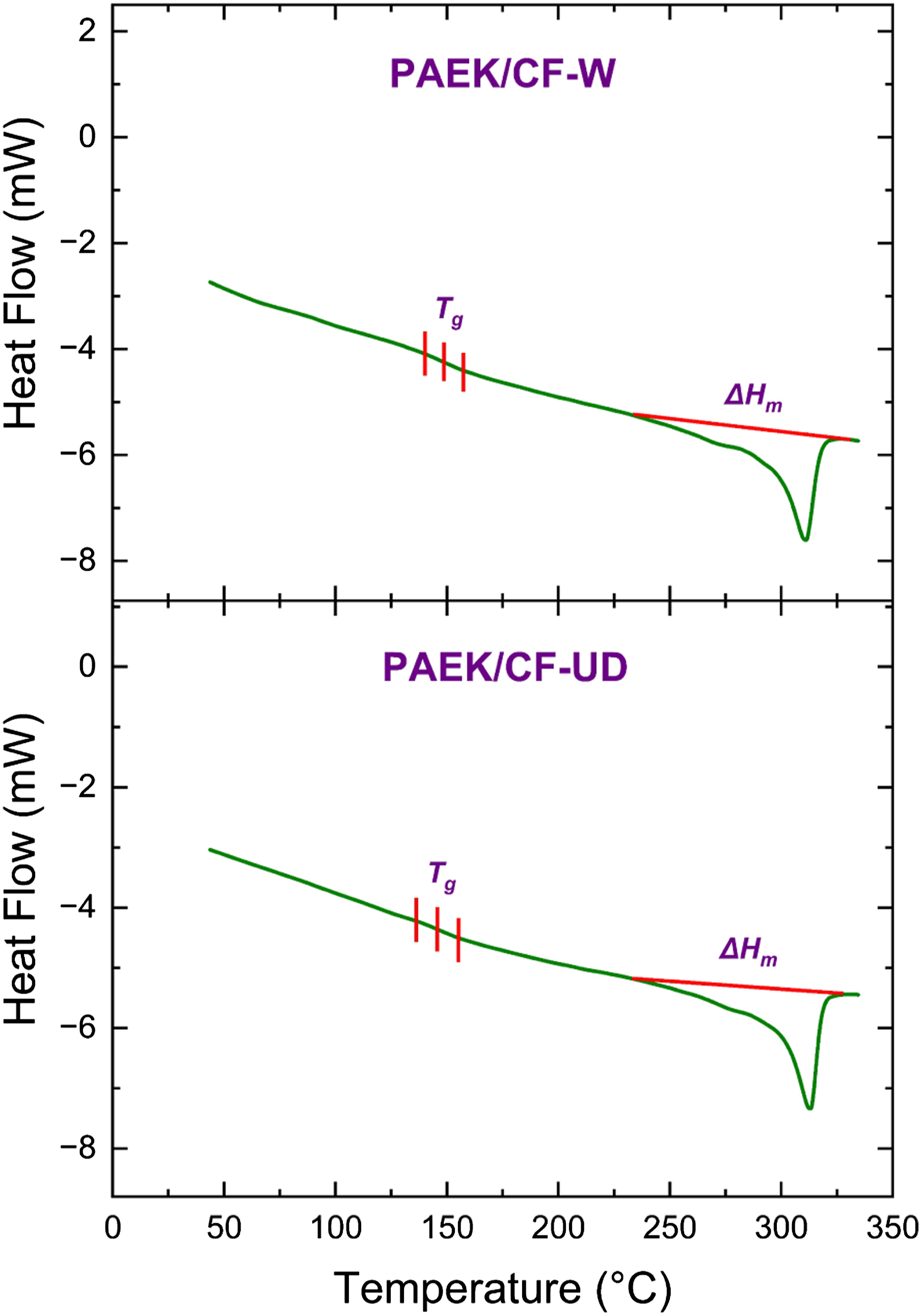
It is seen in Table 5 that Tg of the laminates were between 147–147.5°C while their matrix crystallinity
Determination of the resistance welding parameters for each interlayer forms
As explained in the experimental part, for an efficient resistance welding operation proper temperature-time profile should be used during the four stages of consolidation: Heating, melting, crystallization, cooling. As shown in Figure 4, for the homogenous melting (370 ± 10°C) and proper hot crystallization (220 ± 10°C) temperatures, dwell times for melting and crystallization of the PAEK matrix were determined as 20 s and 90 s, respectively; under the power level of 50 V and pressure level of 6 bars.
Then, in order to determine optimum “amperage” levels required for the heating, melting and crystallization stages of the six different Interlayer Forms, several temperature-time profile studies were conducted by placing thermocouples into the three different locations between the upper PAEK/CF laminates and Interlayer Forms.
One example of these temperature-time profiles obtained from three different thermocouples for the IF-1 Interlayer Form is given in Figure 7. Note that, these curves were all in accordance with the typical temperature-time profiles of the resistance welding of PAEK/CF laminates given in Figure 4 in the experimental procedures section. Example of the temperature-time profile obtained from three different thermocouples for the IF-1 interlayer form.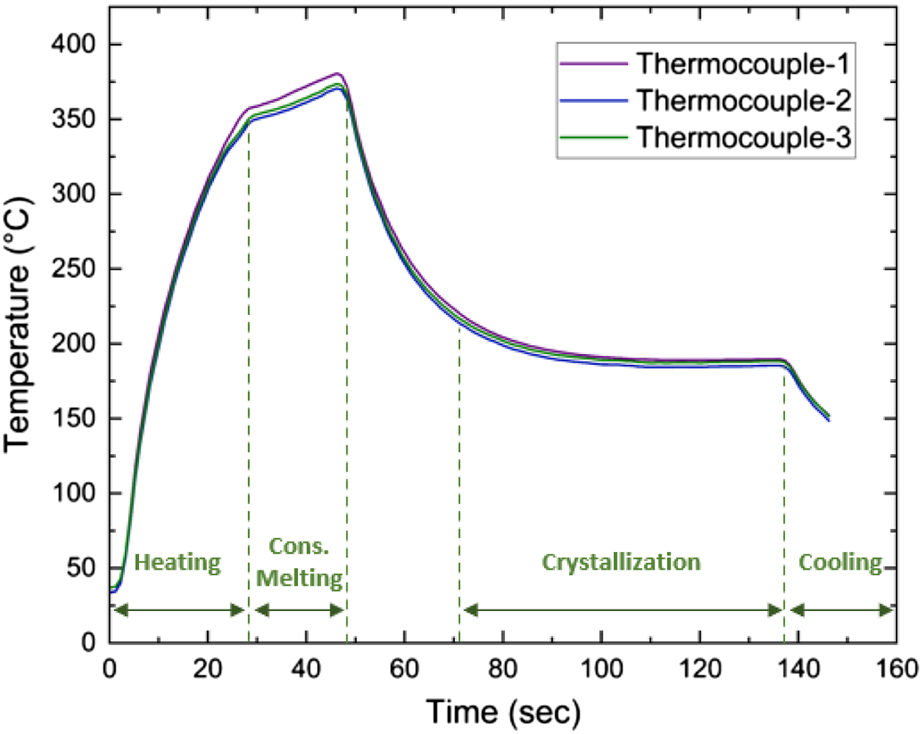
After obtaining all the temperature-time profiles for each Interlayer Forms, optimum “amperage” parameters required for the welding consolidation stages of heating, melting and crystallization were determined. Depending on the lay-up configuration, “amperage levels” determined for the heating, melting dwell and crystallization dwell were in the ranges of 46–100 A, 40–90 A and 25–50 A, respectively,
Ultrasonic inspection of the welded specimens
After welding operations, before the mechanical tests, in order to reveal possibilities of void formation and delamination, welded laminate strips were inspected by Automated Ultrasonic Through Transmission (AUTT) and Manual Ultrasonic Pulse Echo (MUPE) techniques. For six different Interlayer Forms, four welded laminate strips were inspected on the images obtained in the form of C-Scan mapping (Figure 8). C-scan images obtained from the AUTT inspection of the four welded strips for six different interlayer forms.
Figure 8 generally shows that IF-1 and IF-4 Interlayer Forms with IG1 Insulating Glass Fiber layer (having the highest areal weight) had rather uniform color mapping, while the other Interlayer Forms with IG2 and IG3 insulating layers (having lower areal weights) had C-Scan maps with certain degree of suspicious areas having sound wave attenuations (decibel losses). After the C-Scan mapping, MUPE technique was also used to confirm the sound wave attenuations detected during AUTT inspection.
As will be discussed in the following section, those welded specimens with IF-1 and IF-4 interlayer forms (having IG1 insulating layer) resulted in higher mechanical performance. On the other hand, other Interlayer Form configurations having IG2 and IG3 insulating layers resulted in lower interlaminar properties.
Effects of interlayer forms on the mechanical performance of welded specimens
In this study, effects of interlayer forms on the mechanical performance of welded specimens were investigated by conducting three tests; Interlaminar Fracture Toughness Energy under Mode-I (G
IC
) and Mode-II (G
IIC
), and Single Lap Shear Strength (SLSS). After obtaining load versus displacement curves during these tests (Figure 9), mechanical properties of G
IC
, G
IIC
and SLSS were calculated for the specimens having six different Interlayer Forms. Average values with standard deviations are evaluated in Figure 10 and Table 6. Load versus displacement curves obtained during G
IC
, G
IIC
and SLSS tests. Effects of interlayer forms on the interlaminar fracture toughness (G
IC
, G
IIC
) and shear strength (SLSS) values of the welded specimens. Average values of the interlaminar fracture toughness (G
IC
, G
IIC
) and interlaminar lap shear strength (SLSS) values of the welded specimens with six different interlayer forms.
It is clearly seen that welded specimens with IF-1 interlayer form had the highest level of mechanical performance. Their G IC and G IIC Interlaminar Fracture Toughness values were as much as 3.76 and 4.71 kJ/m2, respectively. Similarly, their SLSS Interlaminar Shear Strength was as much as 37 MPa. It is known that these mechanical performances could be sufficient for many structural applications made from composite laminates.
Figure 10 and Table 6 also indicated that welded specimens with IF-4 interlayer form had similarly high-level mechanical performance (especially in terms of G IC and G IIC ) with the ones having IF-1 interlayer form. The only difference between these Interlayer Forms is their “Heating Element” layers designated as HE1 and HE2.
As tabulated in Table 2, both HE1 and HE2 layers are made of “Stainless Steel Meshes”, having certain differences in terms of “Mesh Style” and “Areal Weight”. Since both of them resulted in higher level of mechanical performance, it could be stated that use of these two different Stainless Steel Mesh forms as Heating Element layers (HE1 and HE2), could be considered as an appropriate choice in the resistance welding of PAEK/CF thermoplastic composite laminates.
The common layer in IF-1 and IF-4 interlayer forms was their “Insulating Layer” designated as IG1, which is actually a “Woven Glass Fiber” layer impregnated with the matrix resin. Thus, it could be interpreted that the main reason of having very high-level mechanical performance in the welded specimens with IF-1 and IF-4 interlayer forms should be due to their common IG1 insulating layer.
On the other hand, Figure 10 and Table 6 revealed that those welded specimens having IG2 and IG3 insulating layers in their Interlayer Forms had rather lower-level mechanical performance. For instance, welded specimens with IF-6 interlayer form (i.e. having IG3 insulating layer) had the lowest mechanical properties. Their G IC and G IIC Interlaminar Fracture Toughness values were as low as 1.82 and 2.62 kJ/m2, respectively. Similarly, their SLSS Interlaminar Shear Strength was as low as 16 MPa. These decreases, compared to the welded specimens with IF-1 were −51%, −44% and −56%, respectively.
Then, it could be pointed out that, in the resistance welding of PAEK/CF laminates, if Stainless Steel Mesh layers were used as the Heating Element, then the type of the Woven Glass Fiber form as the Insulating Layer become very crucial. For instance, use of IG1 could be considered as a perfect choice compared to the lower performance of IG2 and IG3.
What is the difference between the IG1 and the other two IG2 and IG3? Table 3 indicates that although all of them are made of woven E-glass fibers, the main differences are their “Fiber Diameter”, being 6 μm for IG1 and 5 μm for the others; and more significantly their “Areal Weight”, being 296 gsm for IG1 and only 105 gsm and 48 gsm for the others. This means that during resistance welding operations, use of thicker and heavier Woven Glass Fiber insulating layers would perform their functions much more properly and efficiently.
It is known that during resistance welding the main function of the electrically “Insulating Layer” present in the “Interlayer Form” was to prevent current leakage to the other layers in the composite laminate. This phenomenon is called “Current Leakage” problem being one of the significant issue during resistance welding operations. Because if current leakage occurs to the upper or lower composite laminates during welding, then not only voids could form in the thermoplastic matrix, but also delamination might occur in the upper or lower composite laminates being welded.
Apart from “Current Leakage” problem, another issue encountered during resistance welding operations is named as “Short-Cut” problem. This problem takes place if the Stainless-Steel Mesh heating element touches to the carbon fiber reinforcement present in the upper or lower composite laminates. Since carbon fiber reinforcements have certain degree of electrical conductivity, current in the Stainless-Steel Mesh heating element would pass to the carbon fiber reinforcements, leading to “Short-Cut” in the welding interface. Due to the loss in the magnitude of the current, melting stage of the welding would not take place properly, resulting in improper welding.
Of course, these two problems (Current Leakage and Short-Cut) directly depend on the efficiency of the Insulating Layers. If Insulating Layers (IGs) electrically insulate the Heating Element layers (HEs) properly from the upper and lower composite laminates, then these issues would be not significant.
Therefore, it can be concluded that, in this study, use of rather thicker and heavier Woven Glass Fiber insulating layers, i.e. use of IG1, was very efficient to prevent problems of Current Leakage and Short-Cut during resistance welding operations of PAEK/CF composite laminates.
As discussed in the Literature Review section, no reported research was found on the resistance welding of PAEK/CF composite laminates; thus it was not possible to compare welding performance obtained in this study with the other PAEK/CF studies. However, limited number of studies on PEEK/CF and PEI/CF23,24,28,30,31 conducted mechanical tests to observe welding performance of their systems. In those studies, SLSS values were determined within the range of 19.60–34.46 MPa while G IC values were found to be within the range of 0.41–3.60 kJ/m2. Note that, for PAEK/CF laminates in this study, SLSS and G IC values were determined as 36.77 MPa and 3.76 kJ/m2 for IF-1 interlayer form, respectively. It was seen that, interlaminar mechanical properties obtained for PAEK/CF laminates were all above the values obtained in the other studies conducted for PEEK/CF and PEI/CF laminates.
Interlaminar failure modes observed during testing of welded specimens
It is known that when welded composite laminates are loaded; depending on the weld quality and the applied load direction, “interlaminar failure” might occur in various ways. As shown in Figure 11, after interlaminar fracture toughness tests (such as G
IC
, G
IIC
) and interlaminar shear strength tests (such as SLSS), generally four typical interlaminar failure modes are observed; (i) cohesive failure, (ii) adhesive failure, (iii) delamination failure and (iv) mixed failure (i.e. mixture of the others). In this study, after all mechanical tests, interlaminar failure modes of the welded specimens were examined. Typical examples observed during G
IC
, G
IIC
and SLSS tests are given in Figures 12–14, respectively. Four typical interlaminar failure modes; (i) cohesive, (ii) adhesive, (iii) delamination and (iv) mixed failure that might be observed during the mechanical tests of welded specimens. Examples of interlaminar failure modes observed during G
IC
tests. From top to down: cohesive, adhesive, mixed (cohesive and delamination). Examples of interlaminar failure modes observed during G
IIC
tests. From top to down: cohesive, adhesive, delamination. Examples of interlaminar failure modes observed during SLSS tests. From top to down: cohesive, adhesive, mixed (cohesive and delamination).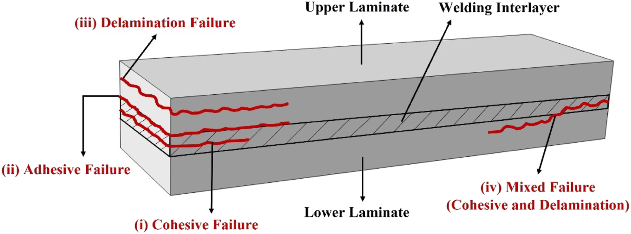
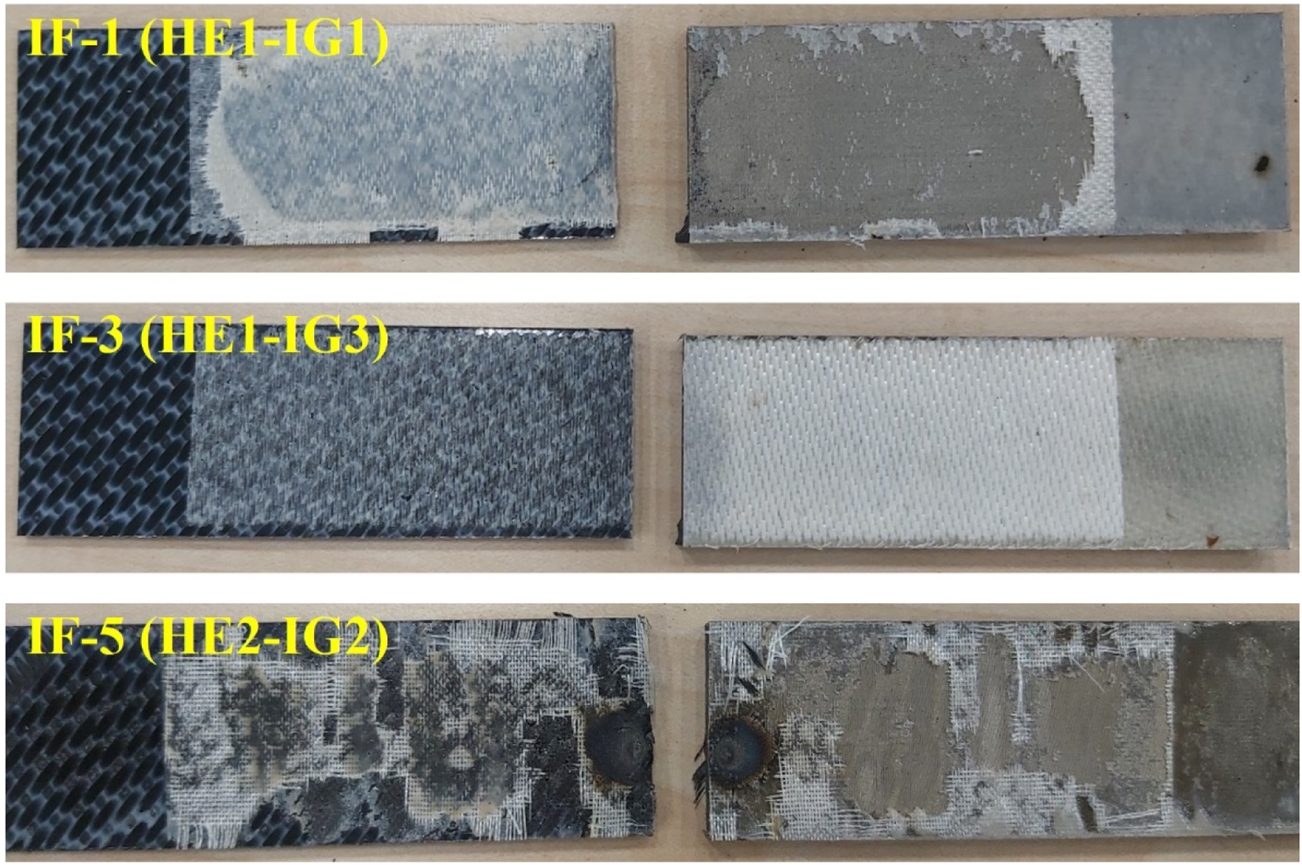
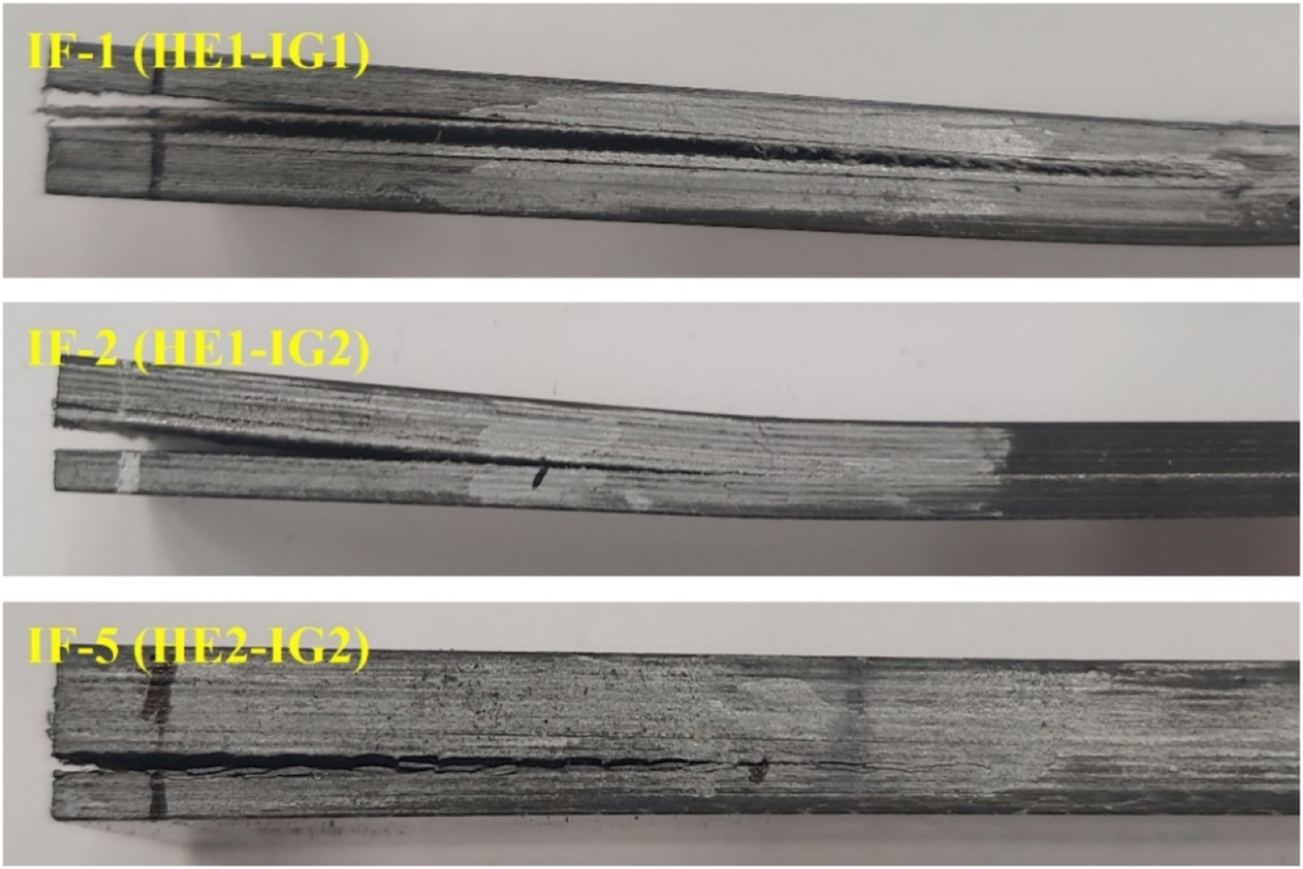
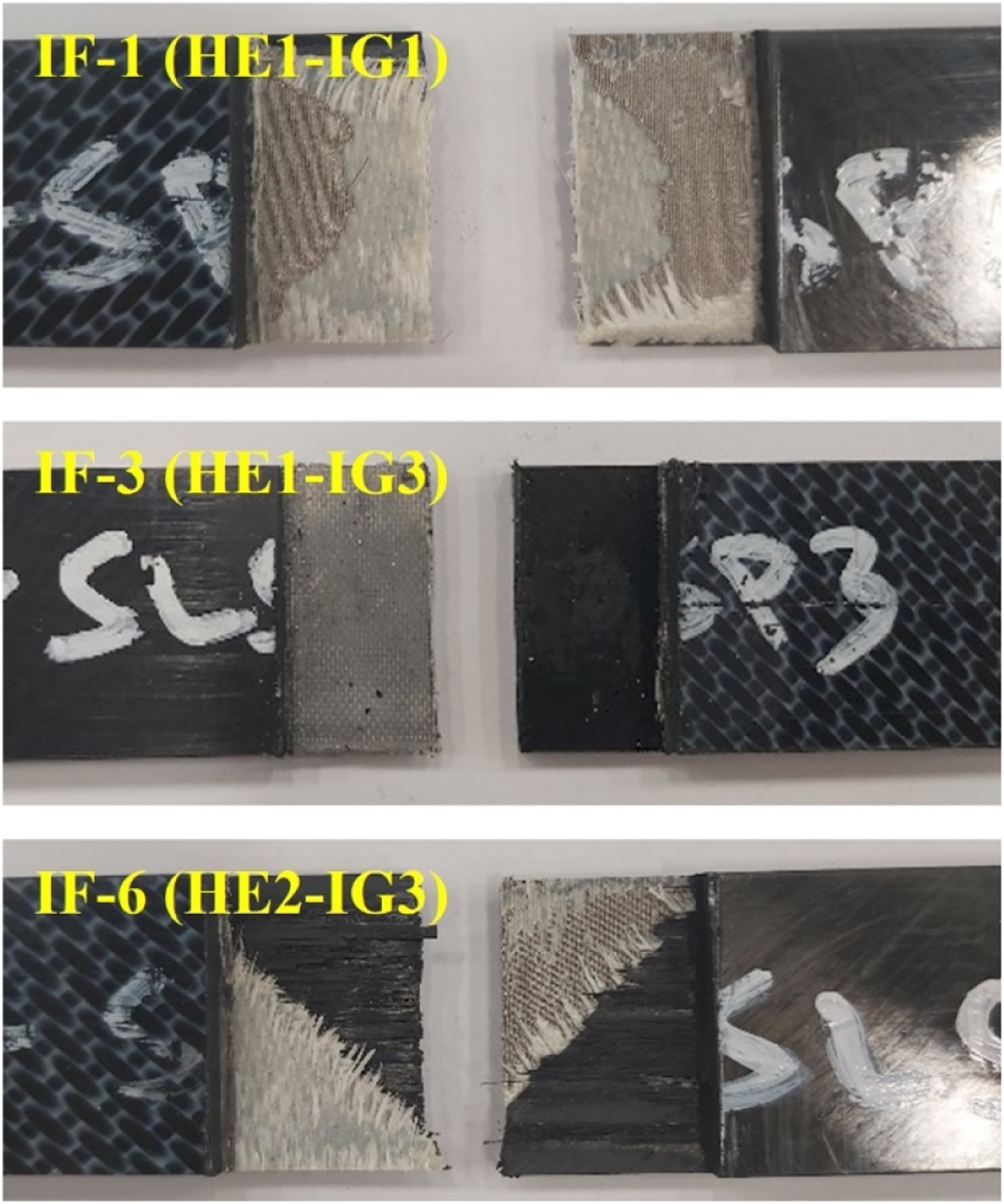
“Cohesive Failure” is defined as the failure i.e. crack propagation along the welding interlayer 33 which represents high quality of the welding operation because the interlaminar failure is not taking place between the weld and the upper or lower composite laminate. In this study, Cohesive Failure was especially observed in the specimens having IF-1 and IF-4 interlayer forms. In this mode, as shown in Figures 12 and 14, weld adherent was observed on both sides (upper and lower) of the joined laminates. It should be noted that these specimens (having IF-1 and IF-4 interlayer forms) also had the highest mechanical properties as discussed before.
“Adhesive Failure” is defined as the failure i.e. crack propagation in between the welding interlayer and upper or lower composite laminates, which represents lower quality of the welding operation because this means that intertwining mechanism between the macromolecular chains present in the PAEK matrix of welding interlayer and the PAEK matrix of the upper or lower composite laminate is not occurring properly. As shown in Figures 12–14, in some of the welded specimens (such as IF-2 and IF-3) having rather lower mechanical properties, Adhesive Failure mode was observed.
“Delamination Failure” is defined as the failure i.e. crack propagation totally through the interlayers of the upper or lower composite laminates, not related to the welding interlayer. 33 This type of interlaminar separation in the welded composite specimens could be due to the problems encountered during specimen production, specimen cutting, improper testing loads, etc. In this study, that kind of interlaminar failure was observed in very limited number of specimens, one example is shown in Figure 13 for the IF-5 specimen. Since this failure mode is not related to the welding operation, their mechanical properties obtained were not included in the average values.
It is known that apart from cohesive, adhesive and delamination failure modes, there is another possibility in the welded composite laminates, which is named as “Mixed Failure”, i.e. a mixture of the other three. In this study, that type of mode was observed in the form of “Cohesive/Delamination Failure” mixture, especially in some of the specimens having IF-5 and IF-6 interlayer forms, as indicated in Figures 12 and 14. In this mode, cracks propagate both in the welding interlayer and in the upper or lower composite laminates. The main reason for this behavior was, as also observed in the C-Scan images of these specimens, presence of the interior defects in the upper and lower composite laminates. Since their Insulating Layers were IG2 or IG3, it was difficult to prevent the “Current Leakage” problem discussed before. Therefore, welded specimens having IF-5 and IF-6 interlayer forms had the lowest mechanical properties.
Microscopic analyses of the welded specimens
In order to assess whether there were any significant changes or not in the Thickness Deviation and Porosity Level of the specimens “after” welding operation, optical microscope inspection with an image analysis software was conducted for all specimens having six different Interlayer Forms. At least three examinations and measurements were taken for each specimen.
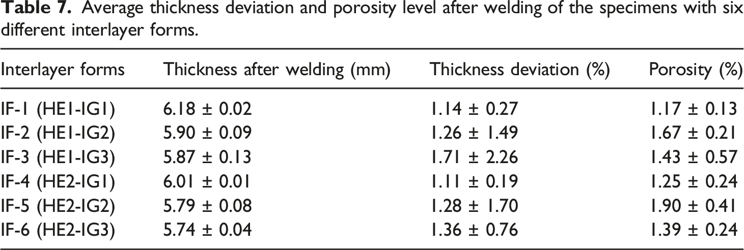
As shown in Figure 15, total thickness of the specimens before and after welding was determined as the summation of the thicknesses of Upper Laminate + Interlayer Form + Lower Laminate. Then, average values of the “Thickness Deviation” and the “Porosity Level” in percentages were tabulated in Table 7. One example of the through-thickness optical microscope image analysis conducted after welding. Average thickness deviation and porosity level after welding of the specimens with six different interlayer forms.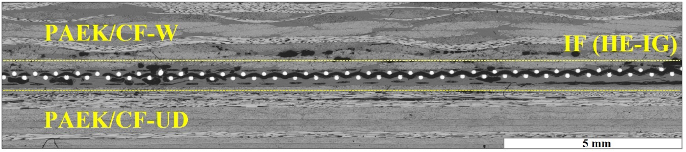
As a general assessment, the main problem was determined as the porosity concentration at the interface which was the expectation coming from NDI results. However, the delaminations observed between the plies of consolidated laminates were not estimated via NDI. These delaminations affect the mechanical performance of the laminates under peel, bending or tensile loading. The reason for them to be formed may be the insufficient pressure applied to the surface of the welding specimens or the duration at the melting region where the electrical current could not be prevented from reaching the consolidated laminate plies. In addition to the interior defects, the thickness deviations calculated for the configurations showed that the pressure was a little bit insufficient for the interlayer forms since the deviations of consolidated laminates are small while the total thickness of the welded specimens is higher than the nominal requirements.
Concerning the individual observations, Thickness Deviation of the specimens after welding was in the range between 1.1% and 1.7%, which could be considered as an acceptance range. Table 7 also revealed that, compared to others, specimens with IF-1 and IF-4 interlayer forms after welding had rather lower Porosity Levels being only 1.17% and 1.25%. Thus, as discussed before, those welded specimens having IF-1 and IF-4 performed with the highest mechanical properties.
DSC analyses of the welded specimens
In order to reveal whether there were any significant changes or not in the Glass Transition Temperature (Tg) and Crystallinity Degree ( Examples of the first heating DSC thermograms of the welded specimens with six different interlayer forms. Glass transition temperature (Tg) and crystallinity degree (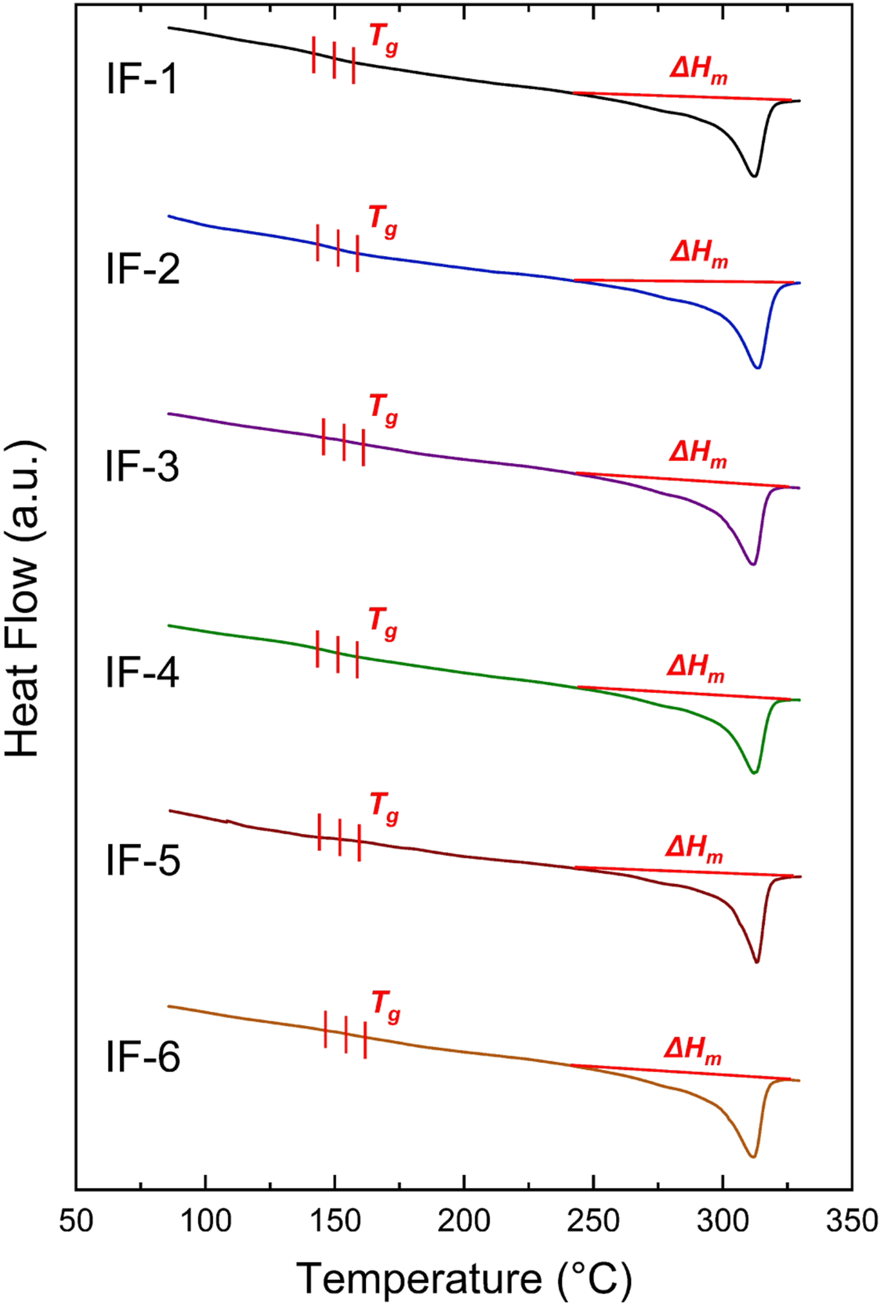
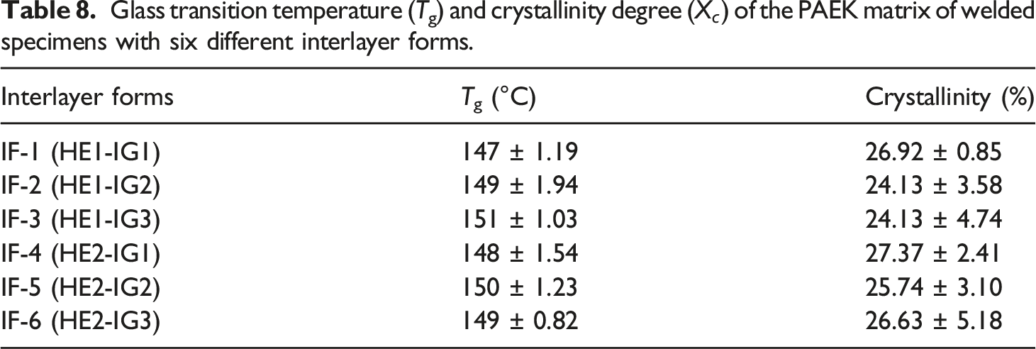
Figure 16 revealed that, just like the DSC analyses conducted for the upper and lower PAEK/CF laminates before welding as shown in Figure 6; during the first heating no cold crystallization enthalpy (
Thus, it can be stated that, resistance welding parameters determined for the welding of PAEK/CF laminates with six different interlayer forms had no detrimental effects on the thermal behavior of the PAEK matrix. That is, temperature-time profiles applied for different specimens resulted in similar Tg values and allowed sufficient time necessary for the expected matrix crystallinity degree.
Conclusions
Main conclusions drawn from the resistance welding studies of PAEK/CF thermoplastic composite laminates can be summarized as follows. • Temperature-time profile studies indicated that during welding consolidation, for the homogenous melting and proper crystallization of the PAEK matrix, their dwell times should be 20 s and 90 s, respectively; under the power level of 50 V and pressure level of 6 bars. Then, for the six different Interlayer Forms, optimum “amperage” levels should be determined for the heating, melting and crystallization stages separately. • After welding operations, Automated Ultrasonic Through Transmission inspection revealed that IF-1 and IF-4 Interlayer Forms with IG1 Insulating Glass Fiber layer had rather uniform color C-Scan mapping, while the other Interlayer Forms with IG2 and IG3 insulating layers had C-Scan maps with certain degree of suspicious areas having sound wave attenuations (decibel losses). • Mechanical tests indicated that welded specimens with IF-1 and IF-4 interlayer forms had the highest level of mechanical performance in terms of G
IC
and G
IIC
Interlaminar Fracture Toughness and SLSS Interlaminar Shear Strength. • The only difference between IF-1 and IF-4 interlayer forms is their “Heating Element” layers designated as HE1 and HE2. Both of them are made of “Stainless Steel Meshes”, having certain differences in terms of “Mesh Style” and “Areal Weight”. Since both of them resulted in higher level of mechanical performance, it could be stated that use of these two different Stainless Steel Mesh forms as Heating Element layers, could be considered as an appropriate choice in the resistance welding of PAEK/CF laminates. • The common layer in IF-1 and IF-4 interlayer forms was their “Insulating Layer” designated as IG1, which is actually a “Woven Glass Fiber” layer. Thus, it could be interpreted that the main reason of having very high-level mechanical performance in the welded specimens with IF-1 and IF-4 interlayer forms should be due to their IG1 insulating layer. • Although IG1, IG2, IG3 insulating layers are all made of woven E-glass fibers, the differences are their “Fiber Diameter” and “Areal Weight”, in which IG1 has much higher values. This means that during resistance welding operations, use of thicker and heavier Woven Glass Fiber insulating layers would perform their functions much more properly and efficiently. • During resistance welding the main function of the “Insulating Layer” present in the “Interlayer Form” was to prevent “Current Leakage” to the other layers in the composite laminate. If current leakage occurs to the upper or lower composite laminates during welding, then not only voids could form in the thermoplastic matrix, but also delamination might occur in the upper or lower composite laminates being welded. • Interlaminar failure mode observations during mechanical tests revealed that four typical modes (cohesive, adhesive, delamination and mixed) might take place depending on the weld performance. Cohesive Failure which represents higher quality of the welding operation, was especially observed in the specimens having IF-1 and IF-4 interlayer forms. • Microscopic analyses proved that Thickness Deviation in all specimen groups after welding was all in an acceptable range, while specimens with IF-1 and IF-4 interlayer forms after welding had the lowest Porosity Level. • For all specimen groups DSC analyses showed that Glass Transition Temperature (Tg) and Crystallinity Degree (
As the final remark, it could be concluded that, resistance welding parameters used for the PAEK/CF specimens with IF-1 Interlayer Form might be considered as the basic proper start for further studies with more welding performance.
Footnotes
Declaration of conflicting Interests
The author(s) declared no potential conflicts of interest with respect to the research, authorship, and/or publication of this article.
Funding
The author(s) received no financial support for the research, authorship, and/or publication of this article.