
Abstract
Disentangled ultrahigh molecular weight polyethylene (DPE) is a high-tenacity and high-modulus material having great potential for impact resistance applications. This research presents a comprehensive experimental study on the effect of orientation on the tensile and low-velocity impact performance of laminates produced from DPE tapes. The laminates were constructed by laying the DPE tape at different orientations followed by compression moulding. Quasi-isotropic laminate showed good tenacity in all directions whereas cross-ply orthotropic laminate showed the maximum tenacity in both the principal directions (0° and 90°). The impact energy absorption by the orthotropic laminate was 61.1% higher compared to that of quasi-isotropic laminate. The results imply that cross-ply laminate is the most suitable one for ballistic applications.
Keywords
Introduction
Lightweight soft body armour made from para-aramid1–4 and ultrahigh molecular weight polyethylene (UHMWPE)5–8 fibres are being used as an advanced system for ballistic protection. Ultrahigh molecular weight polyethylene fibres are gel spun as their melt viscosity is very high whereas para-aramid fibres are manufactured through solution spinning route. In recent times, UHMWPE is getting preference over para-aramid because of the former's high specific strength, modulus, and low density.9–11 Disentangled ultrahigh molecular weight polyethylene12,13 polymer is the advanced version of conventional UHMWPE which is directly converted into the tape by melt processing process. Most of the commercially available laminates and woven fabrics used for ballistic protection are orthotropic in construction.6,8 Several researchers have presented experimental and numerical works on the multi-layered soft body armours considering varying ply orientation, layering sequences, and their impact performance. Nilakantan and Nutt 14 carried out the finite element analysis to study the effect of woven fabric ply orientation with varying ply angles such as 0°, ±15°, ±30°, and ±45°. Among these configurations, ±45° configuration showed the best impact performance. Wang et al.15,16 investigated the effect of projectile velocity, construction, and the number of plies using finite element simulation and experimental work. The angular orientation of plies in the panels consistently increased the energy-absorbing capacity, compared with the aligned panel, depending on the number of plies in the panel. Arora et al. 17 studied the effect of the angular orientation of fabric layers on ballistic impact performance. They reported that higher the number of angular orientations of fabrics within a panel, the better the energy-absorbing capacity. Min et al. 18 reported that the orthotropic multilayer UHMWPE fabrics were 15% less energy absorbent than their quasi-isotropic counterparts due to the increase in stress dissipation area. Zhou et al. 19 examined the ballistic performance of para-aramid woven thermoset composites with varying orientations of fabric layers. The results showed that quasi-isotropic structure exhibited improved ballistic performance compared to orthotropic structures. Zang et al. 20 investigated the ballistic performance of hybrid (ply orientation) and cross-ply laminates-based UHMWPE panels in terms of back face signature. The hybrid panel showed higher impact resistance compared to cross-plied orientation in multi-layered panels. Bajya et al. 21 studied the effect of various structures of DPE laminate at low velocity impact. The study showed that tape-basedcross-plylaminates at optimised temperature exhibited better impact performance compared to other structural forms such as woven twisted tape, untwisted tape, etc. From the existing literature, it is observed that ply orientation in the multi-layer panel, specially with woven fabrics, has been explored and understood well. However, the effect of ply orientation within a single layer of laminate, which is the building block of many structural materials including body armour, is conspicuously missing in the extant literature. To fill this research gap, single layer laminates were prepared from six layers of DPE tape. Thereafter, the effect of tape orientation in single layer laminates was analysed in terms of tensile and impact performance.
Materials and methods
Disentangled ultrahigh molecular weight polyethylene tapes
Disentangled ultrahigh molecular weight polyethylene tape having width of 23–25 mm was obtained from a reputed Indian industry. The thickness and areal density of DPE tape were 0.20 μm and 15 g·m−2, respectively. The mechanical properties were measured as per ASTM D7744. The measured tenacity and modulus of the tape were 1.5 GPa and 65 GPa, respectively 22 . The tape was used to manufacture different laminates with varying orientations.
Preparation of laminates
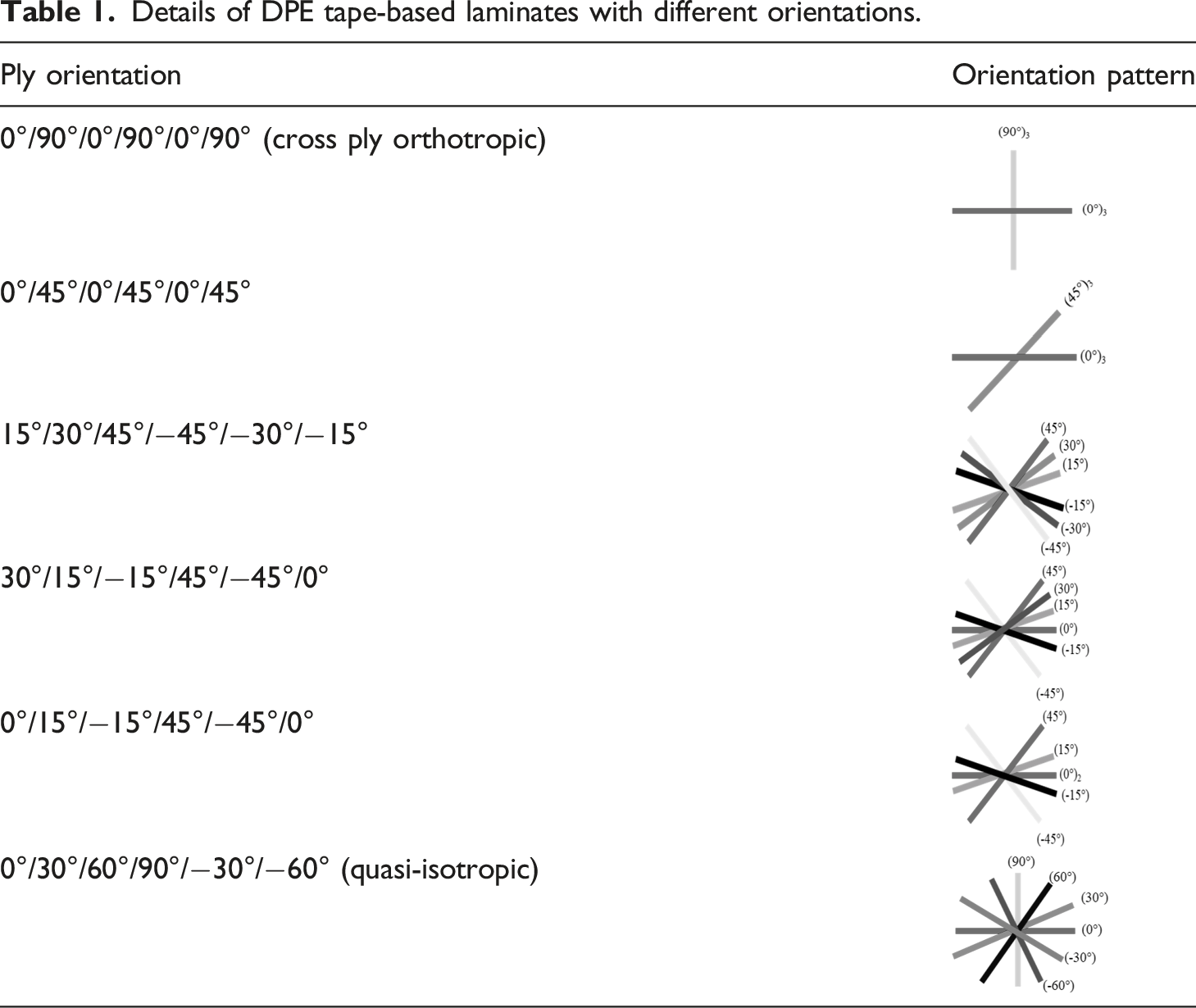
Figure 1 shows the metallic frame (a), laying of lowdensity polyethylene (LDPE) film (b) and pattern of laying of DPE tape (c), and compression moulding machine (d). The edges of the frame were covered with an array of pins to facilitate the mounting of tape strips. Strips of the required length of DPE tape, slightly longer than the distance between opposite edges of the frame, were cut. First, an LDPE sheet was fixed across the frame by fixing it on the peripheral pins. Then, the strips of tape were held taut and fixed following the orientation patterns. Such laying of strips of tapes at different orientations was continued as per the specification of the laminates as shown in Table 1. Finally, another LDPE sheet was laid on the top. The entire assembly was then compressed in a compression moulding machine at 130 °C, 120 bar pressure, for 5 min to form various laminates. The laminate with 0°/90°/0°/90°/0°/90° orientation of tape gives cross-ply orthotropic structure whereas the one with 0°/30°/60°/90°/−30°/−60° tape orientation produces a quasi-isotropic structure. The number of plies of DPE tape and the number of LDPE layers in each laminate were six and two respectively. The overall areal densities of DPE tape and LDPE, within a laminate, were 90 g·m−2 and 30 g·m−2 respectively. Process for the preparation of laminates from tape.
21
Details of DPE tape-based laminates with different orientations.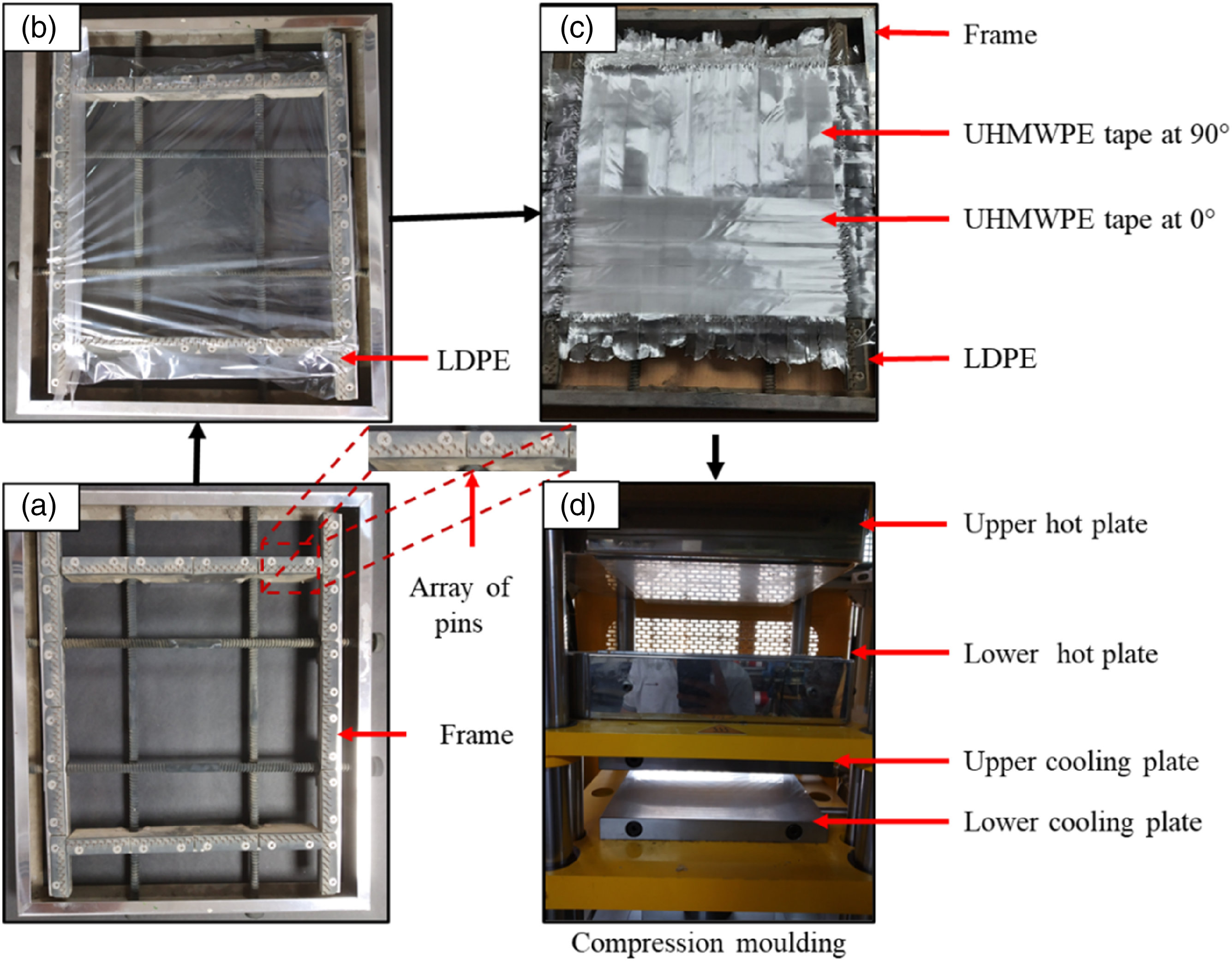
Scanning electron microscopy
The cross-sectional analysis of the laminates was performed by using ZEISS EVO 15 scanning electron microscope. The specimens were sharply cut by using a surgical blade and then mounted on a stub vertically using double-sided silver tape. Sputter-coating of specimens was done with gold to make them conductive. The specimens were dried before testing to avoid charge build-up.
Tensile testing
The tensile properties of laminates were evaluated on the universal tensile testing machine (Tinus Olsen H5KS). The specimens having 250 mm length and 25 mm width were clamped between the two serrated jaws placed 75 mm apart following ASTM D5035. Five specimens were tested for each sample at 0°, 45° and 90° directions at 300 mm·min−1 rate of extension. All the testing was done at standard atmospheric conditions, i.e., 27 °C ± 2°C temperature and 65% ± 2% relative humidity.
Dynamic impact testing
Low velocity dynamic impact tests were performed on UD laminates having dimensions 14 cm × 14 cm. The tests were conducted on a drop tower impact tester (Instron, CEAST-9350) following ASTM D3763 as shown in Figure 2. The laminates were placed between the two circular jaws (inner diameter:76 mm) having knurled metallic surfaces to grip the sample with a clamping force of 7 kN. The diameter of the hemispherical tip of the impactor was 12.7 mm. The impact velocity and total impact energy were 4.88 m·s−1 and of 300 J, respectively. Dynamic impact testing.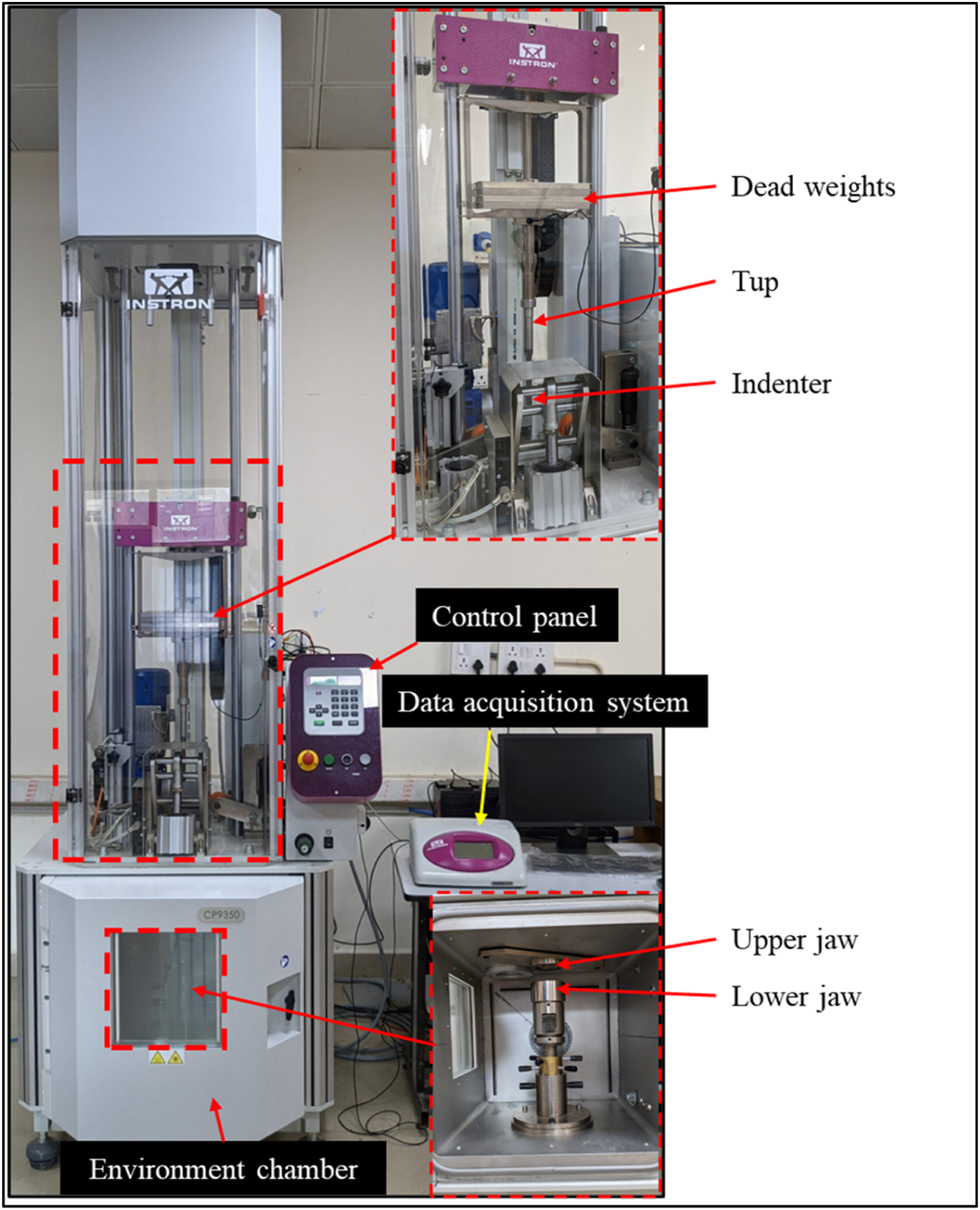
Results and discussion
Scanning electron micrographs of laminates
Figure 3 shows the cross-sectional views of the laminates having different orientations of DPE tape. It is observed that DPE tapes are sandwiched between two LDPE layers without any air gaps. It is also noticed that the separation between layers was observed when the orientation follows the orthotropic pattern (0°/90°/0°/90°/0°/90°). The distinction between layers was difficult to observe in the case of the quasi-isotropic pattern (0°/30°/60°/90°/−30°/−60°). Scanning electron micrographs of laminates with varying ply orientation.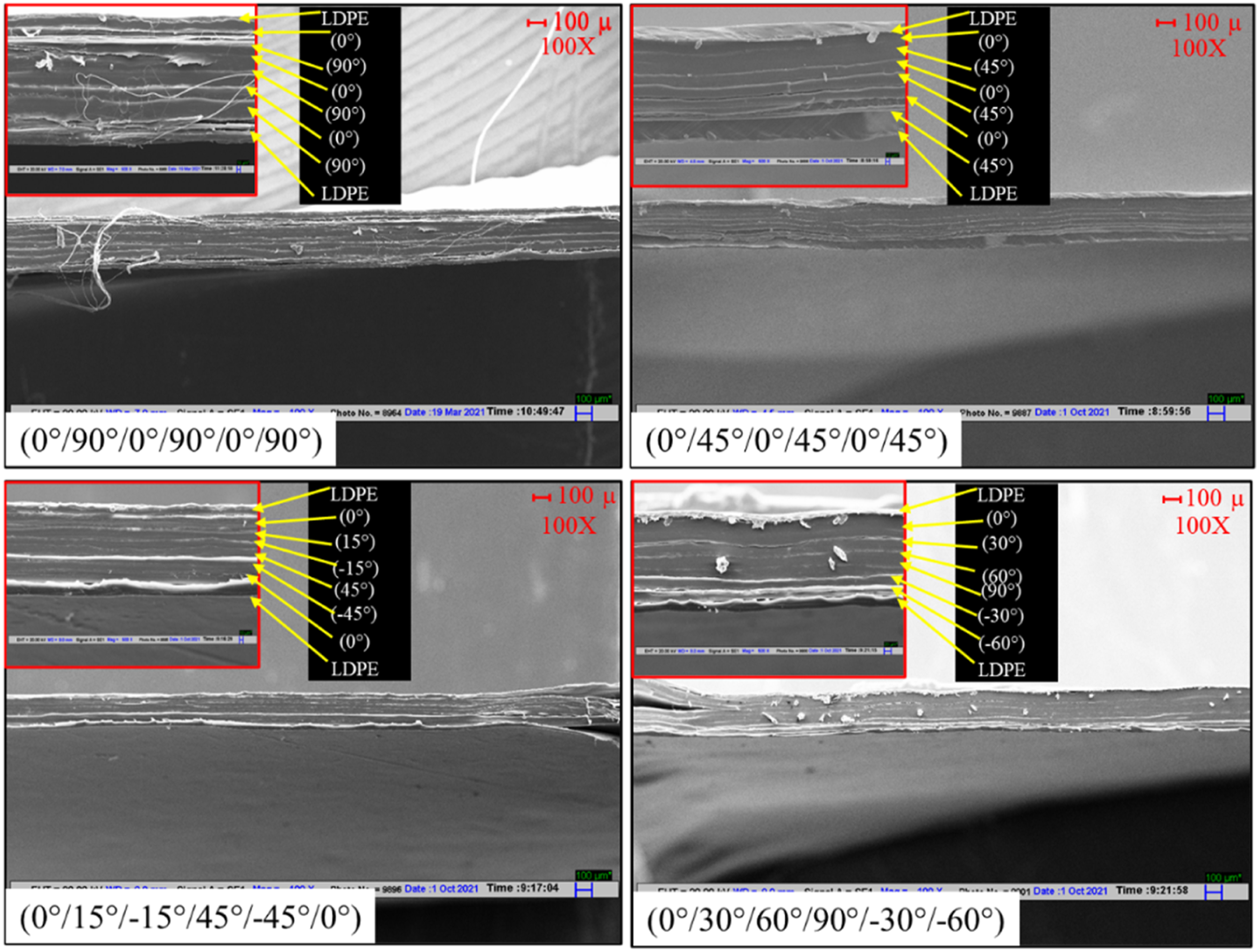
Tensile properties
Figure 4 shows the tenacity of laminates in the primary (0° and 90°) and bias (45°) directions. The cross ply orthotropic laminate (0°/90°/0°/90°/0°/90°) shows the highest tenacity at 0° (0.75 N·tex−1) and 90° (0.70 N·tex−1) and the minimum in bias direction (0.03 N·tex−1). This can be attributed to that fact that this laminate has tapes oriented in two principal directions only. With varying ply orientation, the component contributing to the tenacity also varies, which is confirmed from the tenacity of different laminates. The quasi-isotropic laminate, i.e., (0°/30°/60°/90°/−30°/−60°) yields higher tenacity in bias direction compared to cross ply orthotropic laminate and the former has moderate tenacity (0.36 N·tex−1 and 0.32 N·tex−1) in principal directions (0° and 90°). The laminate having 0°/45°/0°/45°/0°/45° tape orientation shows very good tenacity (0.75 N·tex−1) in only one principal direction (0°) and also in bias direction (0.60 N·tex−1). On the other hand, the laminate having 15°/30°/45°/−45°/−30°/−15° tape orientation shows very poor tenacity in both the principal directions (0.01 N·tex−1 and 0.05 N·tex−1 in 0° and 90° respectively) with moderate performance (0.21 N·tex−1) in biased direction, the latter arising from tape orientation at 45°. Therefore, it can be inferred that the tenacity of the laminates can be tuned as per the requirement by choosing the direction of tape orientations. Tenacity of laminates at different testing directions.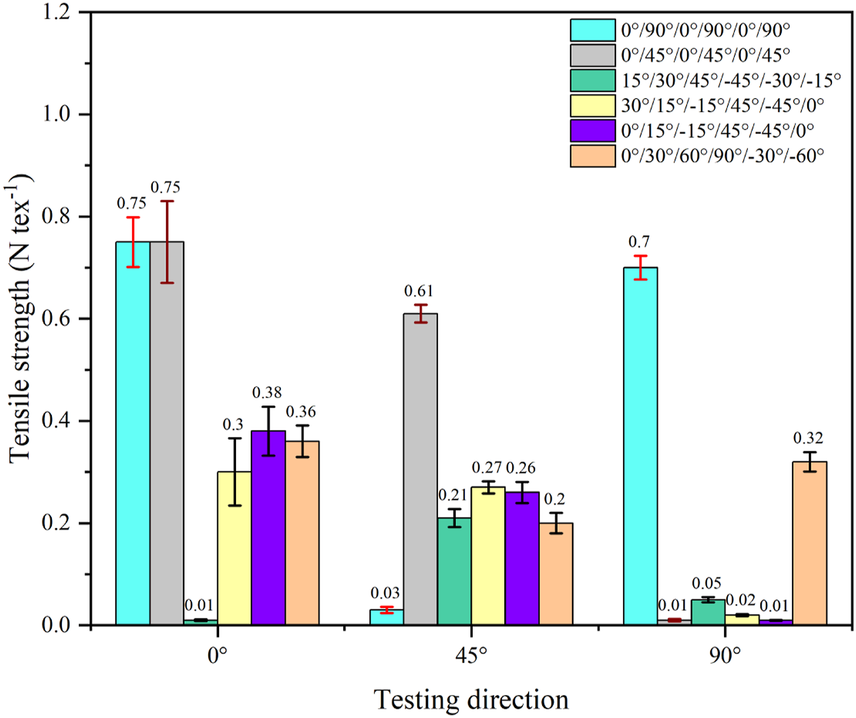
Impact resistance
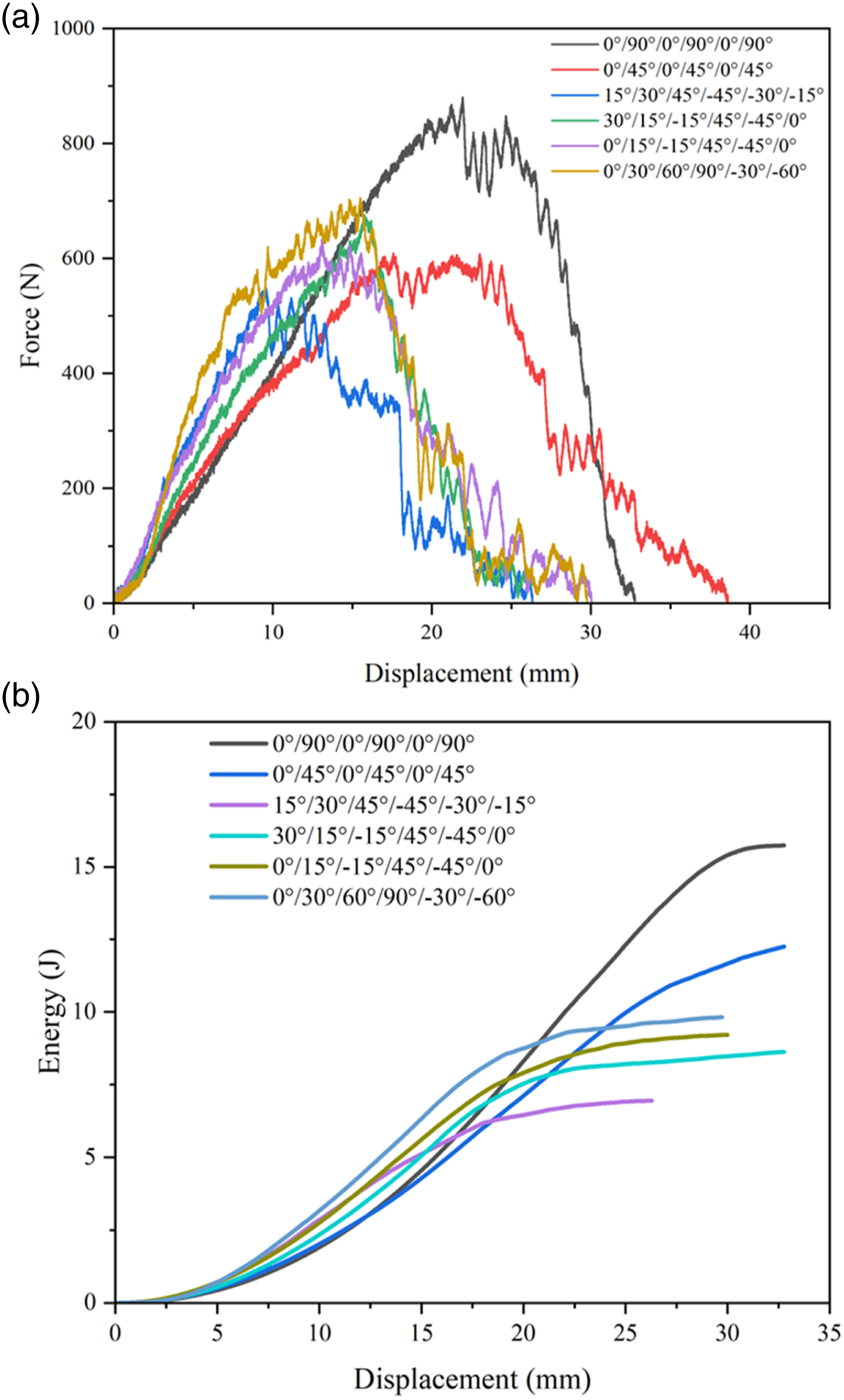
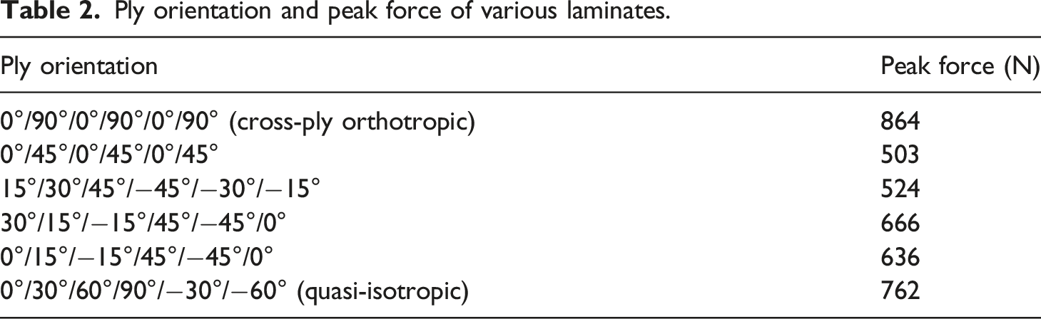
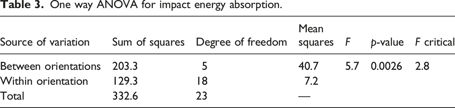
Figure 5 presents the impact energy absorption by different laminates. Figure 6 shows the impact force versus displacement and energy versus displacement plots of various laminates. It is observed that the cross-ply orthotropic laminate shows the maximum impact resistance in terms of energy absorption and peak force as listed in Table 2. The energy absorption of cross-ply orthotropic laminate is 61.1% higher (16.6 J vs 10.3 J) than that of quasi-isotropic laminate. The worst impact performance (8.9 J) is given by the laminate having 15°/30°/45°/−45°/−30°/−15° tape orientations. This can be ascribed to the fact that this laminate is devoid of any reinforcement in the two principal directions. One way-ANOVA was performed for energy absorption to check the statistical significance of tape orientation on impact performance as shown in Table 3. The calculated value of F is found to be 5.7 and 6.5 respectively for impact energy and peak force whereas the F
critical
for the significant difference is only 2.8. This implies that the impact performance of laminates is significantly influenced by the tape orientation (p value of 0.0026 and 0.0013, respectively). Impact energy absorption of different laminates. Dynamic impact performance: (a) Impact force vs displacement (b) Energy vs displacement. Ply orientation and peak force of various laminates. One way ANOVA for impact energy absorption.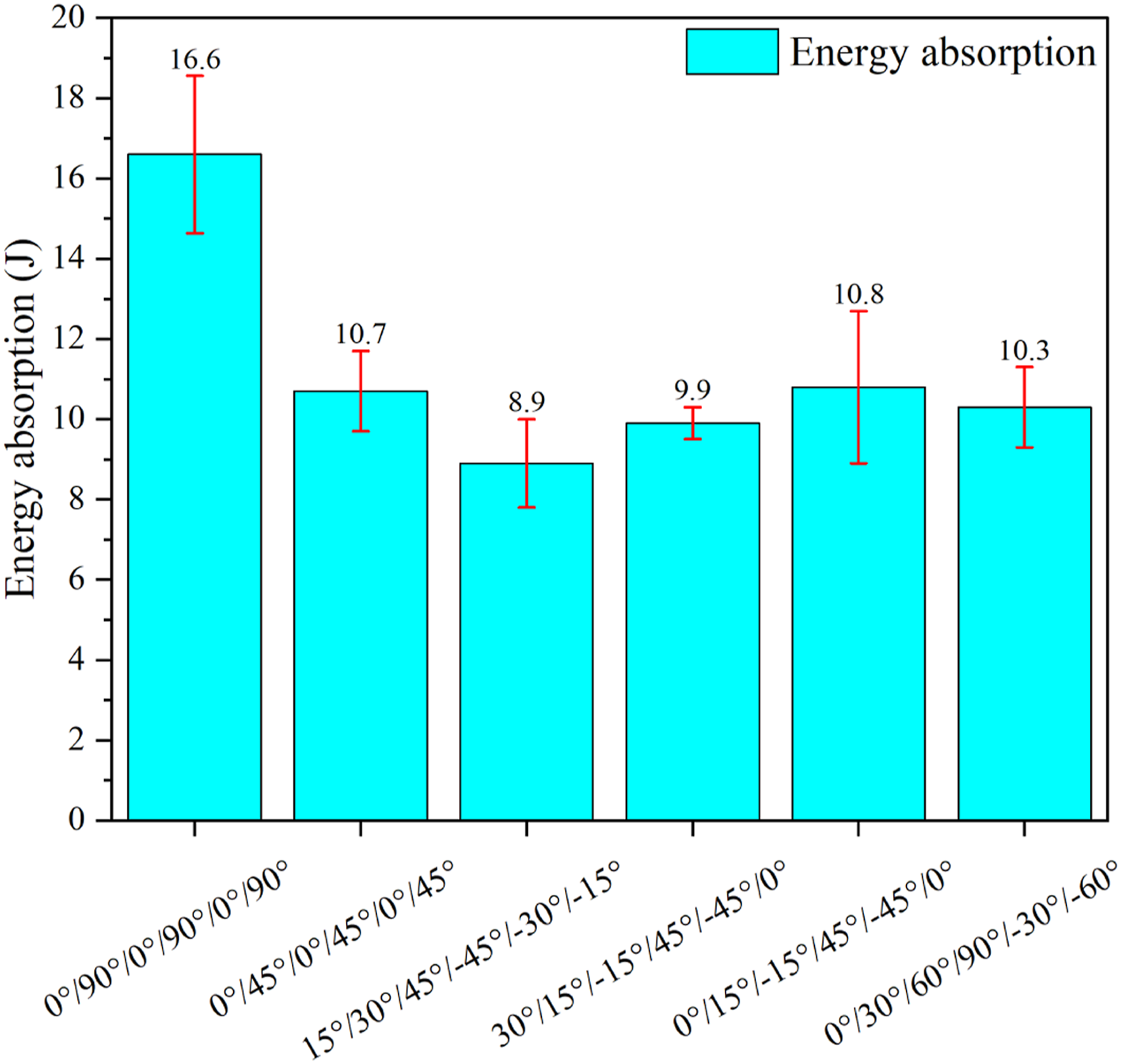
Failure mode analysis
Figure 7 depicts the failure modes of various laminates after the tensile testing. The laminates after the tensile testing at 0°, bias and 90° directions are shown in the left, middle and right of each picture, respectively. Tensile, shear, and mixed mode failures are observed during the tensile testing of different laminates. Pure tensile failure is observed when the orthotropic laminate is tested in primary directions (0° and 90°). However, shear failure is dominant in this laminate when it is tested in bias direction as the alignment of the tapes within the laminate and the direction of applied force are not the same. While testing at 90°, shear failure is dominantly observed in laminates (0°/45°/0°/45°/0°/45°; 15°/30°/45°/−45°/−30°/−15°; 30°/15°/−15°/45°/−45°/0°; 0°/15°/−15°/45°/−45°/0°) which do not have any tape orientation at 90°. Quasi-isotropic laminate shows the mix mode failure, in all three testing directions, as tapes are oriented in the direction of applied force and also at an angle. It can be inferred from the failure mode analysis that the laminates which fail purely in tensile mode show better mechanical performances. As the failure mode changes either to pure shear or to mix mode, energy absorption by the laminates decreases as the contribution due to tensile failure mode reduces. As DPE is a high-tenacity material, tensile rupture ensures the maximum energy absorption by the laminates. Failure modes of laminates in tensile testing.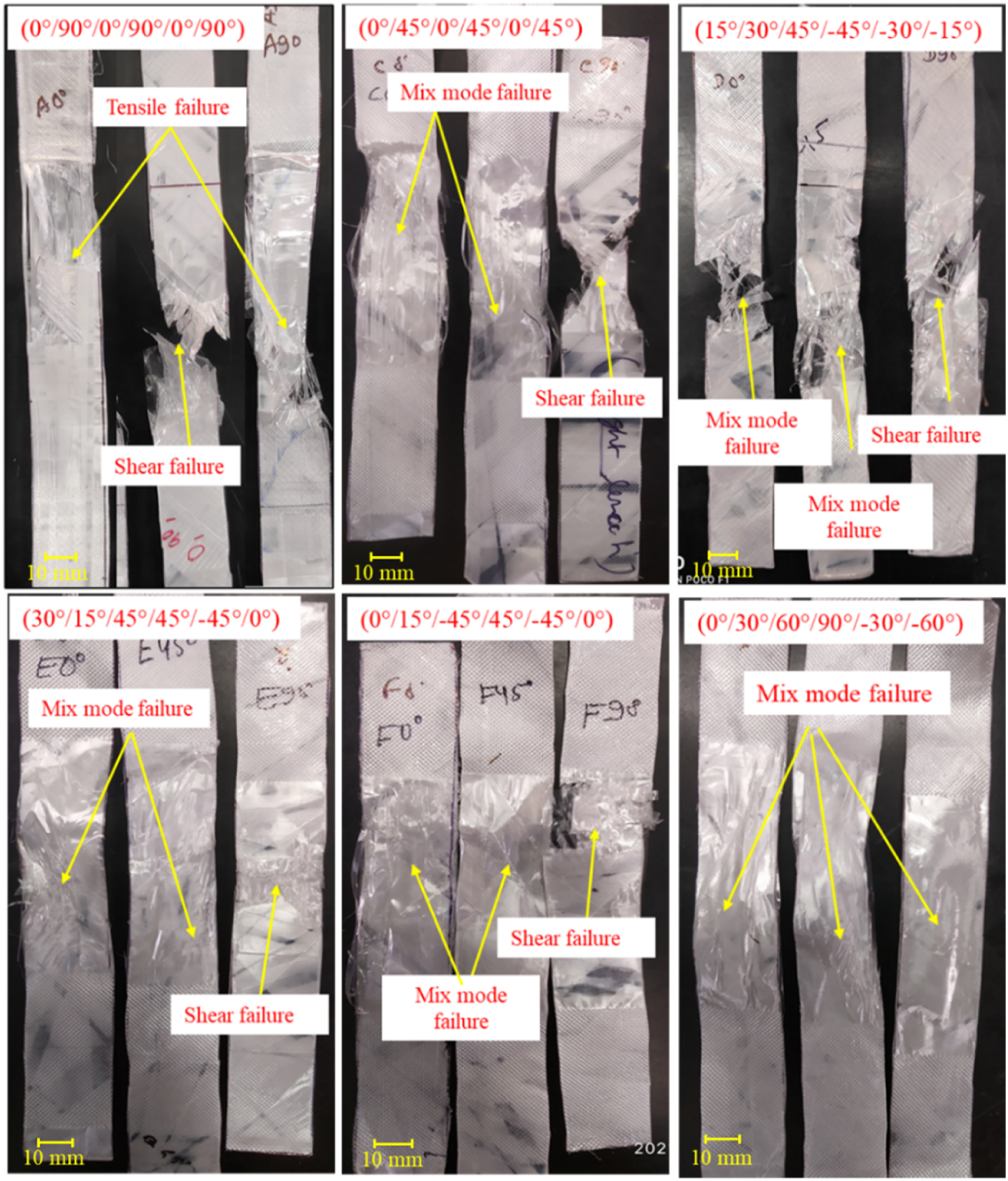
Figure 8 depicts the tested specimen after the low velocity impact performance. Tested laminates after the low velocity impact evaluation were analysed to understand the modes of failure. In general, delamination, tape pull out, tape rupture, wrinkle formation, and windowing effect are observed in the tested laminates. It is observed that the tendency for delamination increases as the ply orientation changes from orthotropic to quasi-isotropic. Tape rupture and tape pull-out are more prominent in cross-ply orthotropic laminate which justifies its superior impact resistance. Failure modes of laminates during impact testing.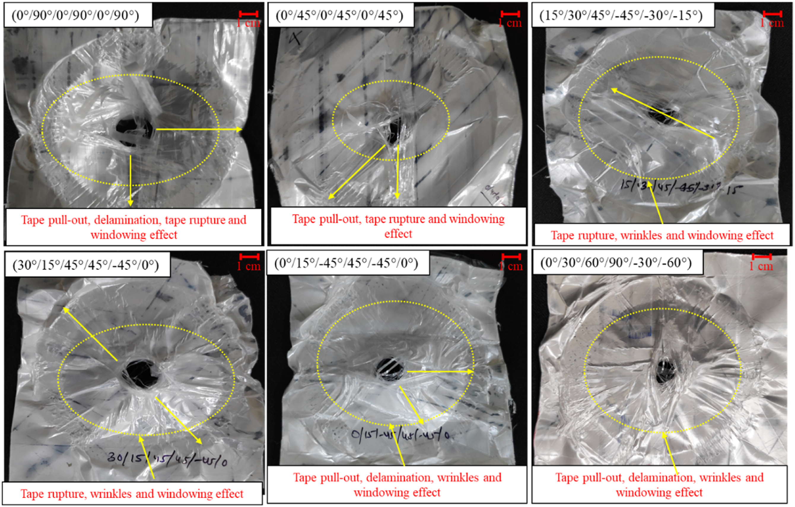
Conclusion
The effect of intra-laminate orientation on the tensile and impact resistance performances of laminates made from DPE tape has been analysed. The results show that the tape orientation significantly affects the tenacity and impact energy absorption capacity of the laminates. Tenacity of cross-ply orthotropic laminate is the highest in both the primary directions (0° and 90°) whereas quasi-isotropic laminate demonstrates moderate tenacity in primary as well as in bias direction. Moreover, cross-ply orthotropic laminate shows dominant tensile failure in primary directions while the quasi-isotropic laminate fails due to the mix mode (tensile and shear) justifying the relatively inferior performance of the latter. Overall, the tenacity of laminates, in different directions, can be tuned by selecting the orientation of the tape. Cross-ply orthotropic laminate shows the maximum impact energy absorption and it is significantly higher than that of quasi-isotropic laminate. Therefore, cross-ply orthotropic laminate is the most suitable structure for low velocity impact resistance applications.
Footnotes
Acknowledgements
The supports of Reliance Industries Ltd. Vadodara, India; Science and Engineering Research Board (SERB), Department of Science and Technology (DST), New Delhi; and FICCI are greatly acknowledged.
Funding
The author(s) disclosed receipt of the following financial support for the research, authorship, and/or publication of this article: The authors are thankful to Reliance Industries Ltd. Vadodara India to providing financial and technical assistances for this research work through Science and Engineering Research Board Grant No. SERB/PM-Fellow/CII-FICCI/Meeting/2018.