
Abstract
In this study, carbon fiber/Elium® composites are manufactured using the resin infusion manufacturing technique. Artificial cracks representing impact-induced delamination are incorporated during layup. The laminates are subsequently healed using several healing parameters. The bonding mechanisms are investigated through microscopic analyses and X-ray Computed Tomography (XCT). The mechanical performance of the healed composites is investigated through four-point bending tests. It is found that as the healing temperature is increased, the cracks are gradually healed by interdiffusion and macroscopic resin flow across each crack interface. The 3D models generated from XCT images show an increase in solid volume fraction from 48% to 70% at the optimum healing parameters. The flexural strength and flexural modulus of the undamaged composites subjected to optimized healing condition are significantly increased relative to the room temperature cured pristine samples. The residual flexural strength of the damaged samples healed at the optimum parameters is 96% of the reference condition. The SEM images confirm that delamination from the previously-healed crack interfaces is the most dominant failure mode in the healed samples, in contrast to fiber fracture and brittle failure in the undamaged reference composite samples. The results show that the damaged composite laminates can be effectively healed and repaired to as good as undamaged laminates using the interdiffusion mechanism.
Introduction
Fiber reinforced polymer composites (FRPCs) have become a key material in the modern aviation, automotive, defense and marine industries, because of their high strength, lightweight, durability, corrosion and chemical resistance.1–5 A number of techniques have been developed over the years to manufacture FRPCs, including hand-layup, autoclave manufacturing, pultrusion, injection molding, automated fiber placement (AFP) and vacuum assisted resin transfer molding (VARTM). 6 Amongst these techniques, VARTM is one of the most commonly used and cost-effective liquid composite molding (LCM) techniques used to manufacture high quality, large composite structures having a near-net shape. Conventionally, a thermosetting resin is used to saturate a fabric based preform in the VARTM process under vacuum. In a move towards sustainable composite manufacturing, scientists and engineers are investigating thermoplastics as an alternative to non-recyclable thermosetting resins. This transition towards thermoplastics is driven by multiple advantages, such as recyclability, post-formability, high chemical resistance, superior energy absorption capability and unlimited shelf life.6–11
The move towards the adoption of thermoplastics as matrices in continuous fiber reinforced composites, especially in aerospace applications, is relatively new. Ongoing research areas involves manufacturing FRPCs based on high-performance thermoplastics, such as polyetheretherketone (PEEK), polyamides (PI) and polyetherketoneketone (PEKK). 3 However, processing these high-performance thermoplastics is quite challenging and requires extremely high temperatures, typically above 350°C.3,12 Additional complications arise from the high-melt viscosities of these polymers, leading to improper impregnation, unsaturated regions, higher levels of porosity and reduced fiber-matrix bonding. 13 An alternative research is focusing on the development of innovative, low-viscosity thermoplastic resins that are compatible with LCM techniques. In this context, ARKEMA has developed a range of infusible thermoplastic resins (under the trade name Elium®), having low-viscosities ranging from 100 to 200 mPa.s, that is comparable to those of thermosetting resins. 14 Significant research has been conducted on Elium® based composites, reporting major breakthroughs in terms of mechanical performance,11,15–17 recyclability, 18 thermoformability 18 and weldability.19,20 Among all these topics, the recyclability of Elium® resin, due to its thermoplastic nature, stands out. A number of studies adopting different techniques to highlight the recyclability of Elium® resin and the effect of recyclability on its composites have been reported in recent years.21–23 Nevertheless, the true potential of Elium® composites, in terms of repair and healing of the delaminated or cracked composite laminates, is yet to be explored in detail.
One of the major drawbacks associated with laminated composites is their susceptibility to delamination, which is one of the key factors differentiating their behavior from metals. 24 FRPCs are based on multiple fabric layers, stacked together and joined using a liquid resin to form a laminate. These layers can be delaminated under cyclic stress or impact loading, leading to catastrophic delamination failure. 25 Delamination in laminated composites is attributed to the presence of high interlaminar shear stresses coupled with a low through-thickness strength. The phenomenon arises because fibers laying in the plane of a laminate do not provide any reinforcement through the thickness hence the composite relies on relatively weak matrix to carry loads in that direction. 24 One of the primary causes of delamination failure in FRPCs is out-of-plane loading, such as, impact caused by dropped tools, bird strike or stones picked up by aircraft tires. 24 Impact-induced delamination can reduce the load-bearing capability of a composite structure by up to 50%. 26
A major concern following delamination failure is the repair of laminated composites, especially those based on thermosetting resins. However, owing to the molecular structure of thermoplastics, two polymer surfaces placed in contact with each other can be easily joined together via a mechanism based on interdiffusion theory, 27 if the polymer chains are sufficiently mobile (i.e. the temperature is above the glass transition temperature (Tg)).28–30 Such a bonding process is often termed as self-bonding or autohesion, where the joining process is initiated through polymer chain diffusion across the interface, followed by chain bridging and crystal growth, ultimately resulting in a strong bond between the two layers. 31 Mobile polymer chains at temperatures above the Tg diffuse across the interface through reptation motion, a mechanism first defined by de Gennes 32 and later described by Doi and Edwards. 33 A number of studies have been reported in the literature on self-bonding of thermoplastics,34–37 however, its application to FRPCs has not been properly explored yet. Recently, Khan et al. 2 reported the first study on crack-healing of infusible thermoplastic composites based on Elium® resin and successfully recovered up to 65% of the Mode I fracture toughness of self-bonded composites. A number of other studies have also focused on the delamination behavior of Elium® composites. Bhudolia et al. 38 recently prepared wholly thermoplastic composites based on Elium® resin modified with 10 wt.% of acrylonitrile butadiene styrene (ABS) particles and reinforced with ultra-high molecular weight polyethylene (UHMWPE) and ultra-high molecular weight polypropylene (UHMWPP) fibers. A comprehensive delamination study comprising of Mode I loading showed that fracture toughness of the thermoplastic composites modified with ABS particles was improved by around 14%. In another study by the same research group, 39 it was reported that the Mode I fracture toughness of Carbon_UHMWPP/Elium® composites was improved by 22% compared to their thermosetting counterparts. This superior fracture toughness was primarily attributed to the excessive plastic deformation of the thermoplastic matrix as well as to the micro-cracks on the debonding surface. The delamination behavior of Elium® composites is also observed to correlate to the delamination failure observed in other thermoplastic composites. For example, Vieille et al. 40 reported that plasticity in PEEK and polyphenylene sulfide (PPS) matrices also plays an important role to limit the impact-induced delamination compared to conventional thermosetting matrix. Liu et al. 41 also reported better delamination resistance for CF/PEEK composites compared to their thermosetting counterparts.
In this study, artificially delaminated carbon fiber/Elium® composites representing impact-induced delamination failure are manufactured through the VARTM technique and subsequently healed by adopting different healing parameters. The quality of the healed laminates is investigated using optical microscopy and an XCT analysis. Raw XCT images are used to create 3D models for an in-depth analysis of the healing phenomenon (which is based on the interdiffusion of polymeric chains and macroscopic resin flow across the crack interfaces). The mechanical performance and the bonding quality of the healed laminates is evaluated through four-point bending tests and dynamic mechanical analysis. Finally, the failure modes present in the fractured specimens are investigated using an SEM analysis.
Materials and methods
Materials
A 2 × 2 twill-weave carbon fabric, based on 3K carbon fibers having an areal density of 195 g/m2 (supplied by Gurit®, UK), was used as reinforcement material. A low-viscosity thermoplastic resin (Elium® 188 O), supplied by Arkema China, was used as the polymer matrix. Elium® 188 O has a viscosity of 100 mPa.s at 25°C, a Tg of 107°C and a density of 1.01 g/cm3. 42 The initiator for the polymerization, Luperox® ATC50 benzoyl per oxide (BPO), was supplied by Sigma-Aldrich Corporation, USA.
Methods
Manufacturing of CF/thermoplastic composite laminates
The CFRP composites containing artificial cracks are manufactured using the VARTM process. Reference laminates (S0) without any cracks are also manufactured alongside the artificially damaged samples. Both types of composites comprised 12 layers of fabric. During the stacking process, rectangular sheets of thin nylon are placed between three carbon fibric layers to mimic three different through-thickness delamination cracks. The artificial crack formation and stacking sequence, as well as the dimensions of each crack in the final composite specimen is shown in Figure 1. In the figure, C1, C2 and C3 refer to three cracks having different lengths. This pattern of cracks is selected since it depicts the nature of damage that is frequently observed in impact-damaged composites. A flow mesh is also placed above and below the fabric layers to facilitate resin flow. Once the injection line and vent connections are made, the mold is covered with a vacuum bag and is sealed with the help of a sealant tape. Experimental VARTM setup along with a graphical demonstration of the layout and dimensions of the artificial cracks.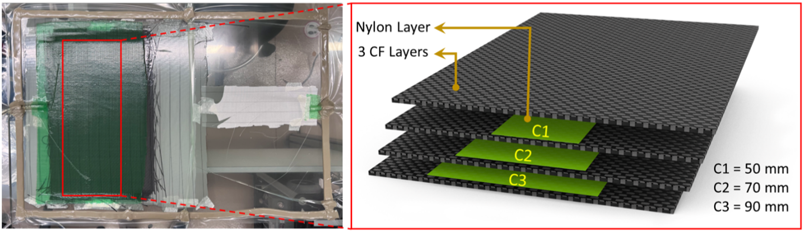
As per manufacturer’s recommendations, a 1.5% BPO initiator is mixed with the thermoplastic resin for 5 min to start the polymerization process. The infusion process is conducted at room temperature and the mold is left to cure for 24 h. This is followed by post-curing in an oven at 65°C for 24 h. Rectangular specimens having a length of 150 mm, width of 12.7 mm and a thickness of 3.5 mm are then cut from the composite panels using an EXTEC Labcut® precision cutting machine. After cutting the specimens, the nylon sheets are carefully removed from all the crack sites using a sharp blade.
Healing of CF/thermoplastic laminates
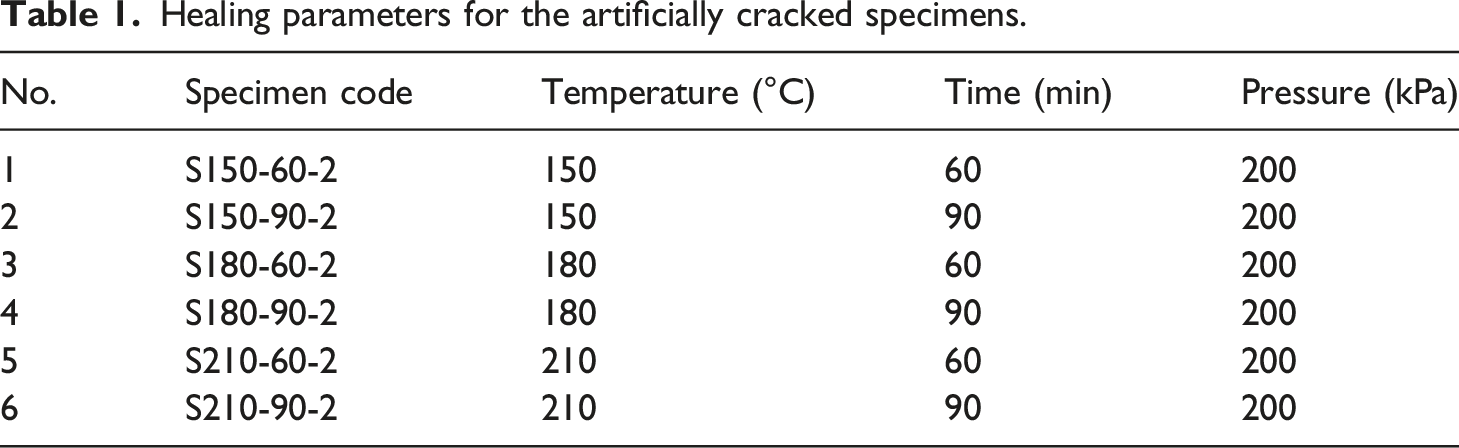
The artificially delaminated composite specimens are repaired using a Meyer® hot platen press (type APV 3530), equipped with dual contact heating platens, having a working area of 350 × 300 mm2. Nylon layers representing the artificial cracks are carefully removed using a sharp blade in order to ensure that they do not act as crack initiation sites after repair. The delaminated specimens are healed for either 60 or 90 min at three different temperatures above the glass transition temperature Tg (107°C) of the Elium® resin, that is, 150, 180 and 210°C. As mentioned in the Introduction section, the underlying principal behind healing of the cracked thermoplastic laminates is based on interdiffusion theory. 27 Based on this theory, two polymer surfaces in contact with each other interdiffuse if the polymer chains are sufficiently mobile (i.e. their temperature is above Tg).29,30,43
Healing parameters for the artificially cracked specimens.
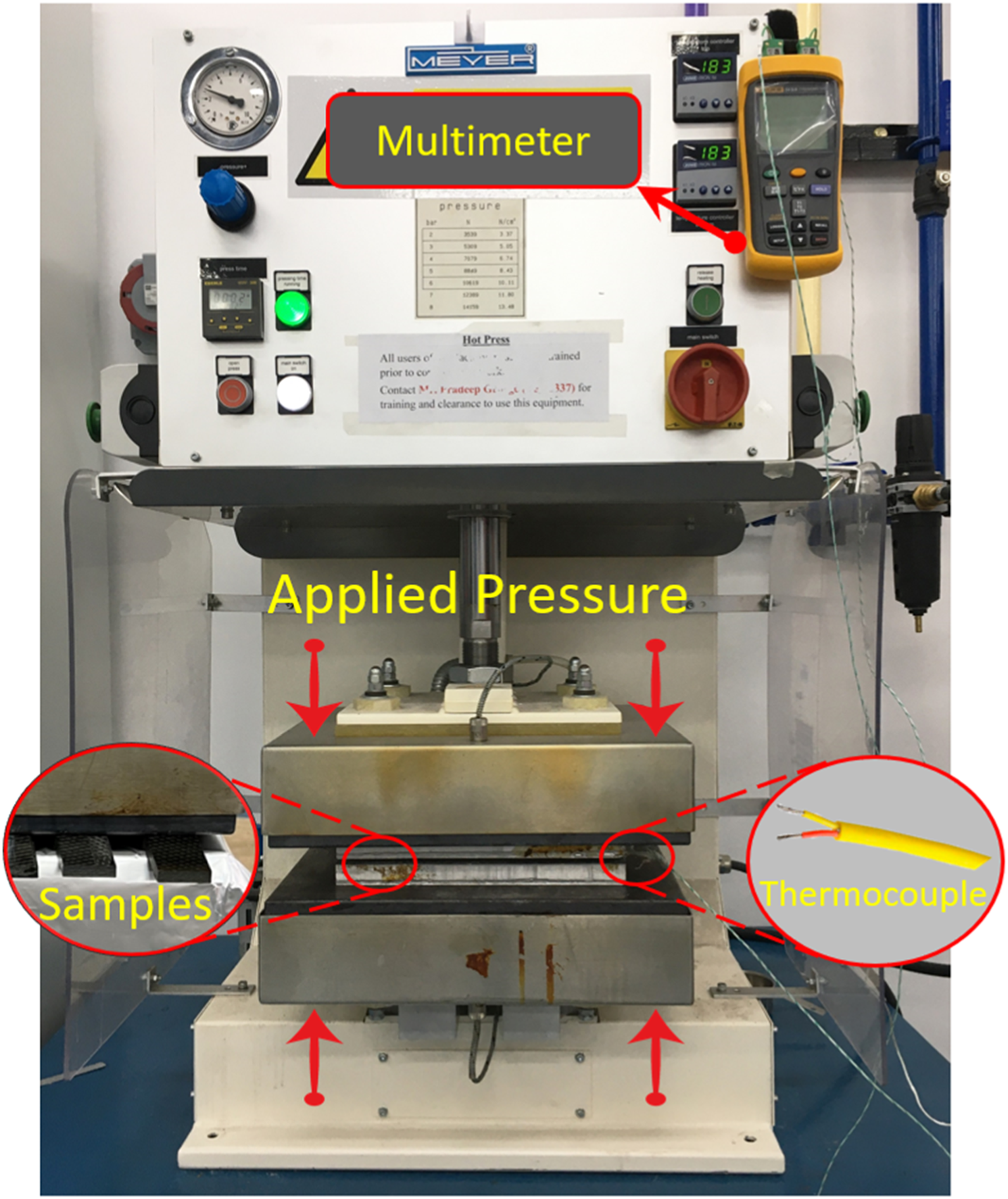
Hydraulic press used for healing the specimens.
Microscopic analyses
Optical microscopy
The quality of the healed specimens is investigated through optical micrographs using a Leica DMS100® digital microscope, with a maximum magnification of 300×. The cross-sections of all the healed samples are carefully investigated at different magnifications. The cross-sectional micrographs of the specimens are helpful in identifying the through-thickness resin flow as well as the porosity before and after the healing process. Furthermore, the thickness variation after healing at different parameters is determined using the 2D-measurement module in the Leica application software package.
Scanning electron microscopy
The morphologies of the fractured specimens after testing in four-point bending are analyzed through scanning electron microscopy (SEM) in order to investigate the microstructural changes, elucidate the failure modes, as well as observe the fiber-matrix interface and resin flow as a result of healing process. The SEM micrographs are obtained using the FEI Quanta 250 FEG-SEM. The SEM results are also compared with the XCT analysis and are helpful in investigating the failure mechanisms at the microscopic level.
XCT analysis
A detailed characterization of both the healed specimens as well as the undamaged samples is undertaken through an XCT analysis by using the GE Phoenix Nanotom® XCT machine.44–46 Rectangular specimens having a length of 50 mm, width of 12.7 mm and a thickness of 3.5 mm were then cut and scanned before and after the bonding process. Additionally, reference specimens without any cracks are also scanned for comparison in terms of fiber volume fraction, resin flow and the amount of defects. A total of 460 radiographic images are captured during the 360° rotation of the sample at a scan resolution of 10 μm. The raw XCT images are then reconstructed into three-dimensional (3D) grey scale volumes. To visualize the individual components of the laminate that is, the fibers, resin and cracks/voids, the greyscale raw volume are segmented using the GeoDict® simulation software package. Global thresholding values are used for the segmentation of the grey scale volume.
47
The segmented models are used to evaluate the volume contents of each of the constituents before and after the healing process. The experimental setup for obtaining the XCT images is shown in Figure 3. Experimental setup for micro-CT images.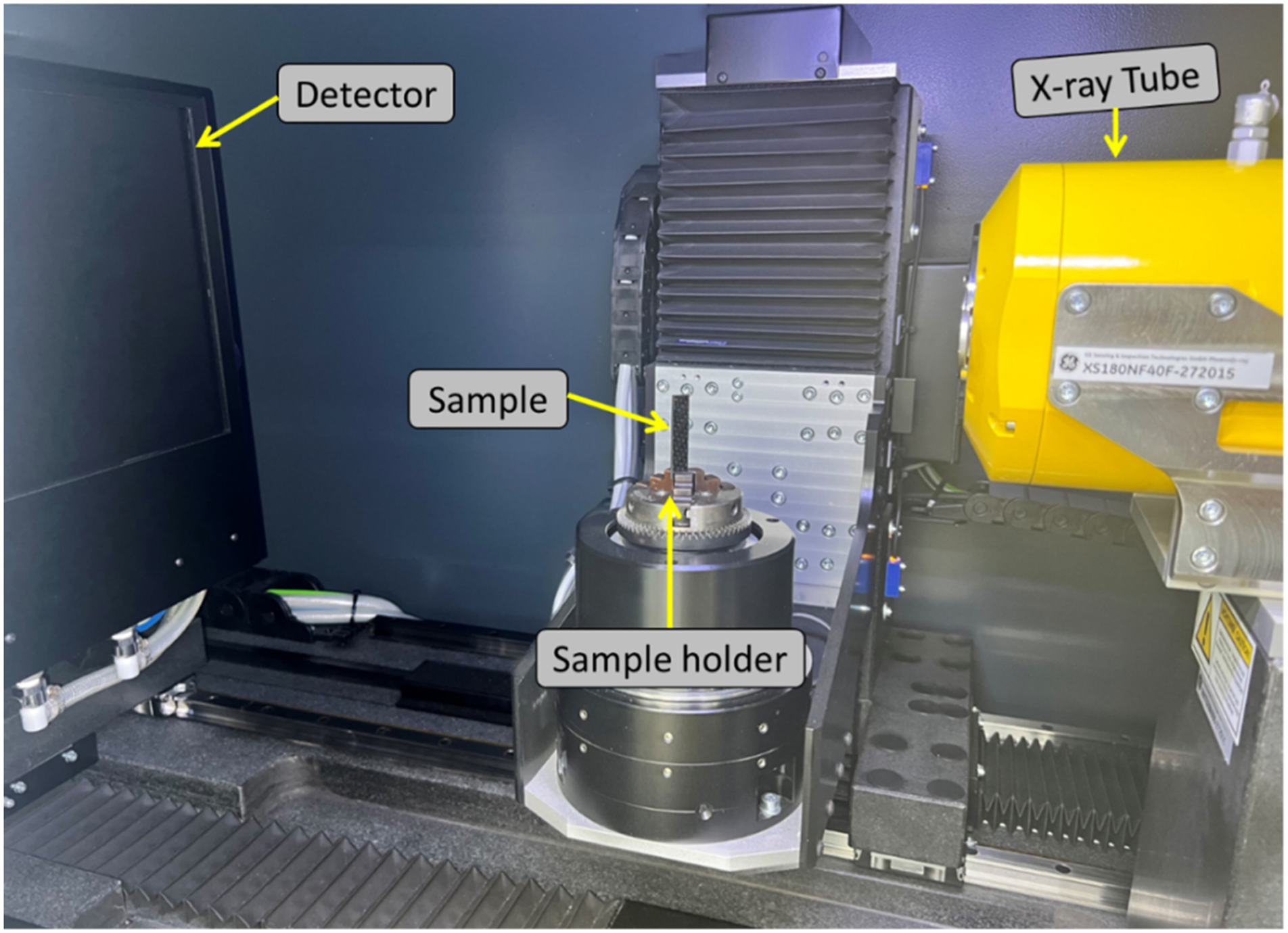
Flexural tests
The mechanical performance of the healed specimens is investigated by subjecting them to four-point bending tests. The tests are conducted using a SATL ST-1004 Hydraulic Universal Testing Machine (UTM) having a load cell capacity of 2 kN. All the tests are conducted according to the ASTM D6272 test standard.
48
The dimensions of the healed test specimens are selected according to the relative test standard as 150 mm (length), 12.7 mm (width) and 3.5 mm (thickness). At least three specimens are tested for each type of healed samples. The loading span is kept constant at 50 mm that is, one half of the support span (100 mm), whereas the span to thickness ratio is maintained constant as 32:1. The tests are conducted at a constant crosshead rate of 2 mm/min. The error bars are calculated by using the 95% confidence interval (CI) formula, (±1.96 .9SD)/√n), where SD is the standard deviation and n is the number of specimens.
49
The results are compared in terms of load versus displacement curves and the flexural strength (residual strength) of the healed specimens. The experimental setup for four-point bending tests is shown in Figure 4. Experimental setup for four-point bending tests.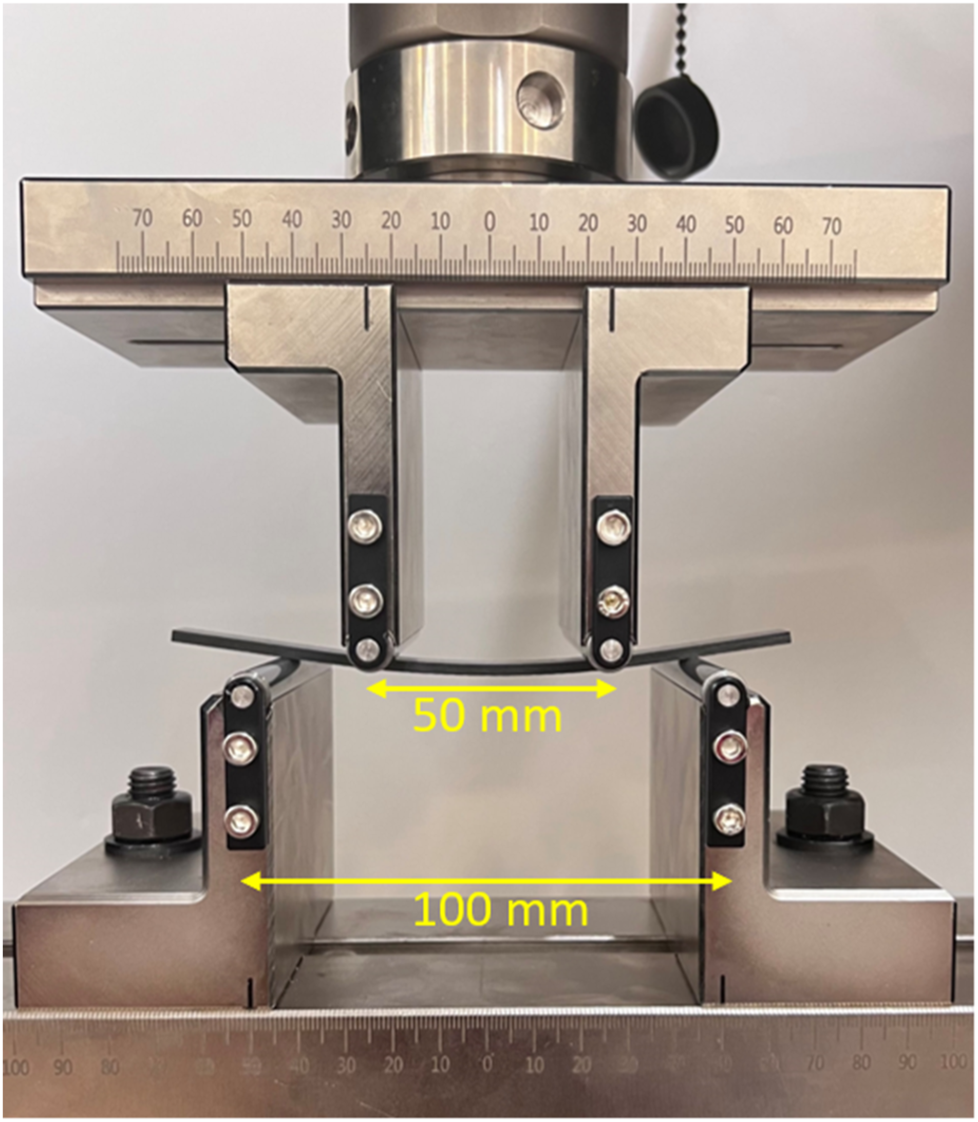
Dynamic mechanical analysis
The variation in the thermo-mechanical properties of the reference specimens (S0) before and after subjecting them to the optimum healing parameters (i.e. 210°C, 90 min and 200 kPa) is investigated through dynamic mechanical analysis (DMA) tests. The DMA tests are conducted using the NETZSCH DMA 242E Artemis test equipment. The tests are conducted in a three-point bending mode, using the temperature ramp program at a constant frequency of 1 Hz. The temperature is varied from 30°C to 150°C at a constant heating rate of 3°C/min, whilst applying a dynamic amplitude of 15 μm. The span of the samples is fixed at 40 mm. At least three specimens are tested for each type of sample and all of the tests are performed according to the ASTM D5023–15 test standard. 50
Results and discussion
XCT analysis
The crack-healing mechanisms are investigated by examining the XCT images. Different slices from the raw volumes are initially considered to investigate the resin flow process and subsequent healing of the interfacial cracks. Additionally, 3D models are generated from the XCT images to investigate the crack/porosity statistics of the samples both before and after healing process at the optimum healing parameters. Initially, 3D models of the composite laminates are created from the raw XCT images using the GeoDict® software and then the region of interest (ROI) is created in the central portion of the voxel geometry. These 3D models are used to conduct a statistical analysis in terms of fiber volume fraction, resin volume fraction and crack/porosity content before and after the healing process. Figure 5 shows raw XCT images comprising of top-view and cross-sections of the pre-cracked regions before and after healing using optimum parameters. These XCT images show that the cracks are completely healed, with there being no visible defects or porosity in the ROI after bonding. A significant reduction in the thickness of the specimens is also observed after healing the cracks. Furthermore, XCT images also reveal that a notable amount of thermoplastic resin is squeezed out of the specimens during the healing process. Consequently, the fiber volume fraction is higher in the healed specimens, a fact that is statistically confirmed by the 3D models. Raw XCT images of (a, c) a sample with an artificial crack and (b, d) sample healed at 210°C for 90 min.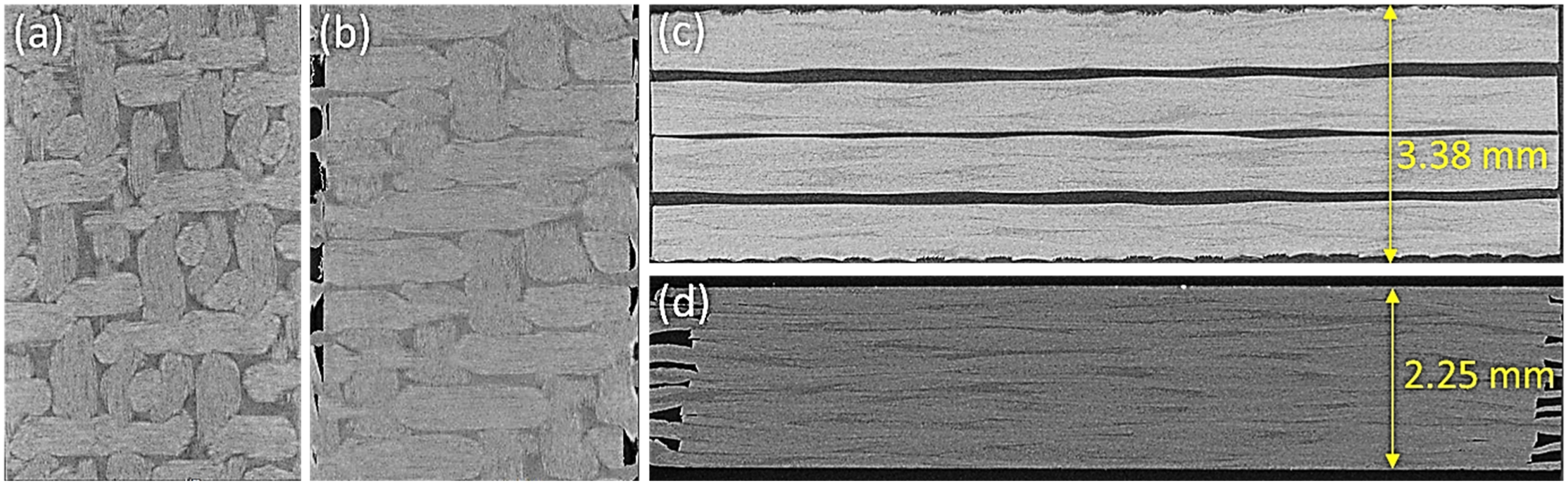
All of the crack healing sites are carefully observed in the XCT images. This is achieved by considering the total thickness of the healed samples and counting the number of through-thickness XCT slices up to the relevant crack interface. The raw XCT images, corresponding to the crack interfaces after healing in the S210-90 specimen, are shown in Figure 6. The XCT images show that the cracks are fully healed without any notable damage or porosity. As highlighted in Figure 6, micro-voids are observed in a small number of regions at the crack interface, as a result of the resin flow. However, these voids have no major influence on mechanical performance of the healed laminates. Along with this, the raw images also confirm no fiber damage or change in the fiber orientation before and after the healing process. Raw XCT images of the crack interfaces of a specimen healed at 210°C for 90 min (a, c) top crack interface and (b, d) middle crack interface (e, f) bottom crack interface.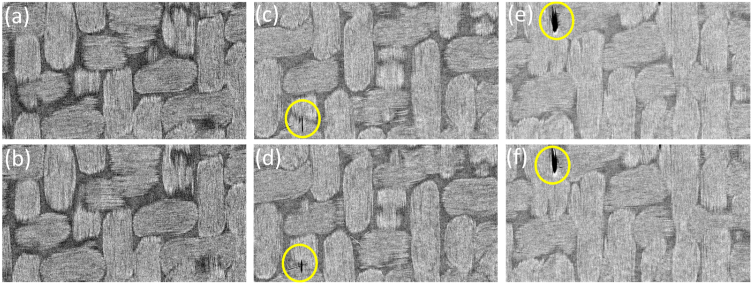
The 3D models generated from the raw images of different specimens are presented in Figure 7. The grey regions correspond to the fabrics, yellow regions represent the resin and cracks/porosity are highlighted in a red color. The volume contents for the fibers, resin and crack/porosity are listed in Table 2. Figure 7(a) shows that the overall level of porosity in the reference specimens is only 0.25%, which highlights the high quality of the prepared samples. It is important to note that the fiber volume fraction is presented in terms of solid volume fraction (SVF). The SVF is defined as the ratio of the solid tows to the total volume of the specimen or ROI.51,52 In contrast to the fiber volume fraction, the SVF provides a better estimation of the solid fiber tows and includes the impregnated resin content within the individual tows. 3D models generated from raw XCT images of (a, b) the reference sample (S0), (c, d) the artificially cracked sample and (e, f) the sample following healing at 210°C for 90 min. Properties of the composite specimens.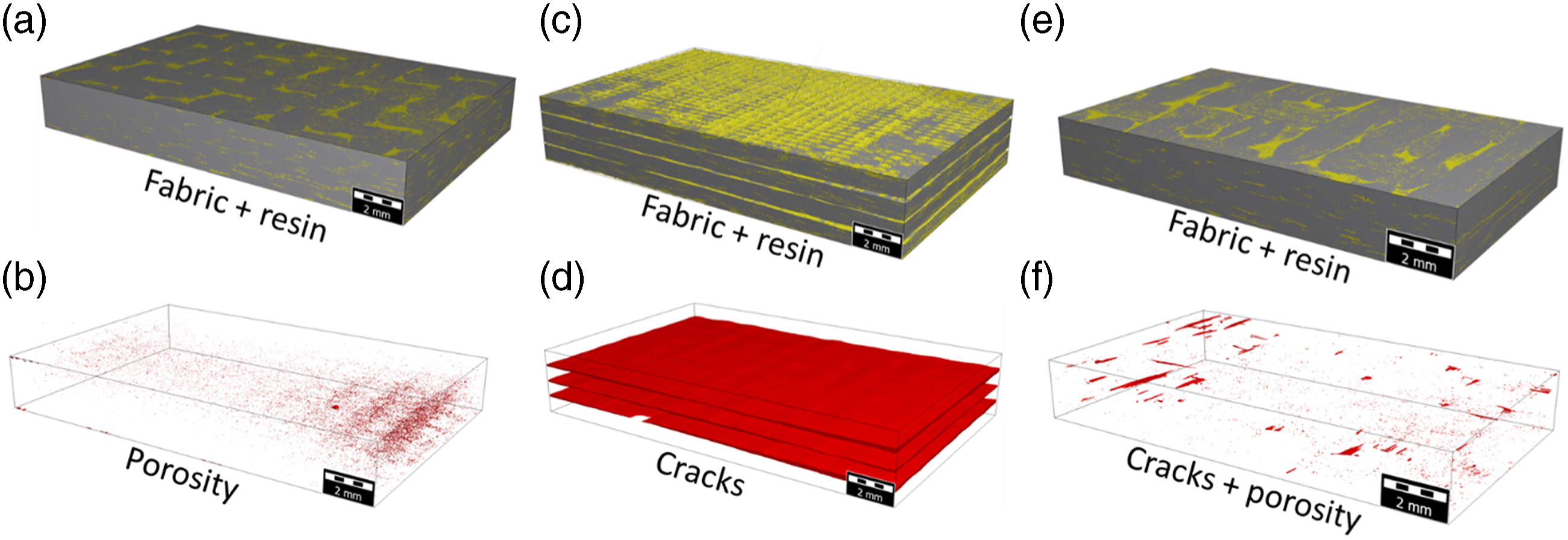
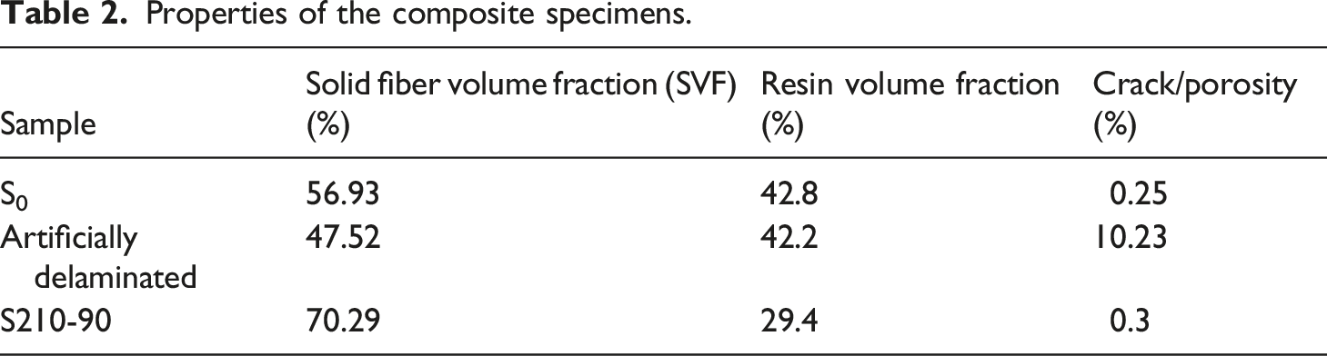
The 3D model of the pre-cracked sample show a crack content of 10.2% before healing. Furthermore, the SVF of the cracked specimens is found to be lower than that of the S0 sample (Table 2). It can be observed in Figure 7(c) and (d) that the pre-cracked specimen is completely delaminated before healing. As the cracks are healed at the optimum parameters, the S210-90 specimens show fully healed crack interfaces (Figure 7(e) and (f)). The crack/porosity content is also reduced to just 0.3%, a value similar to that recorded for the S0 specimens without any pre-cracks. The results also reveal that resin flow occurred throughout the volume of the healed specimens and not only across the crack interfaces. The cracks are healed primarily as a result of molecular diffusion and reptation of the polymer chains across each interface, as discussed in detail in the Optical microscopy section.
In addition to the macroscopic resin flow, the 3D models reveal that healing at elevated temperatures resulted in microscopic resin flow within individual fiber tows. Consequently, the SVF in the S210-90 specimens is significantly increased from 47% to 70%, representing a 48% increase. In addition, the SVF of the S210-90 specimens is also found to be 23% greater than that of the S0 specimens. This increase in SVF is due to mesoscopic resin flow into the individual fiber tows as well as due to the resin flow out of the specimens. Therefore, the healing process yields a compacted specimen with a higher SVF and an improved fiber-matrix interface at a microscopic level (as confirmed from SEM images shown in the Microscopic analyses section). As a result, both the S210-60 and S210-90 specimens demonstrate a superior mechanical performance to that offered by the S0 sample. Therefore, in order to achieve a similar SVF in the reference specimens (S0) and to make conclusive comparisons, the S0 specimens are also subjected to the optimum healing parameters (210°C, 90 min and 200 kPa) and these samples are termed as S0*. All of the results, in terms the mechanical performance of the repaired specimens, in the subsequent sections are compared with the S0* benchmark values.
Flexural tests
The mechanical performance of the healed composite laminates is investigated by subjecting them to four-point bending tests. Typical load versus displacement curves for each healing condition are given in Figure 8(a). It is clear that an increase in both the healing temperature and healing time results in an increase in the flexural properties of the test specimens. The highest average peak load among the healed specimens is 919 N for the S210-90 specimens, whereas the lowest average peak load value is exhibited by the S150-60 specimens (315 N), as shown in Table 3. The maximum flexural strength (σ) of the healed specimens is calculated based on the relative ASTM standard using equation (1):
48
Load displacement curves following four-point bending testing. Flexural properties of the healed composite laminates. S0, reference sample without crack and; S0*, reference sample repaired at 210°C for 90 min.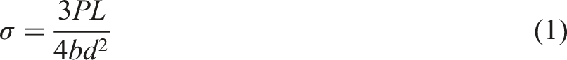
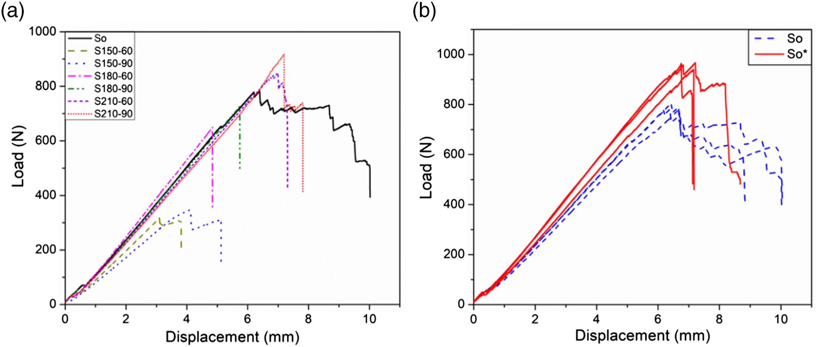
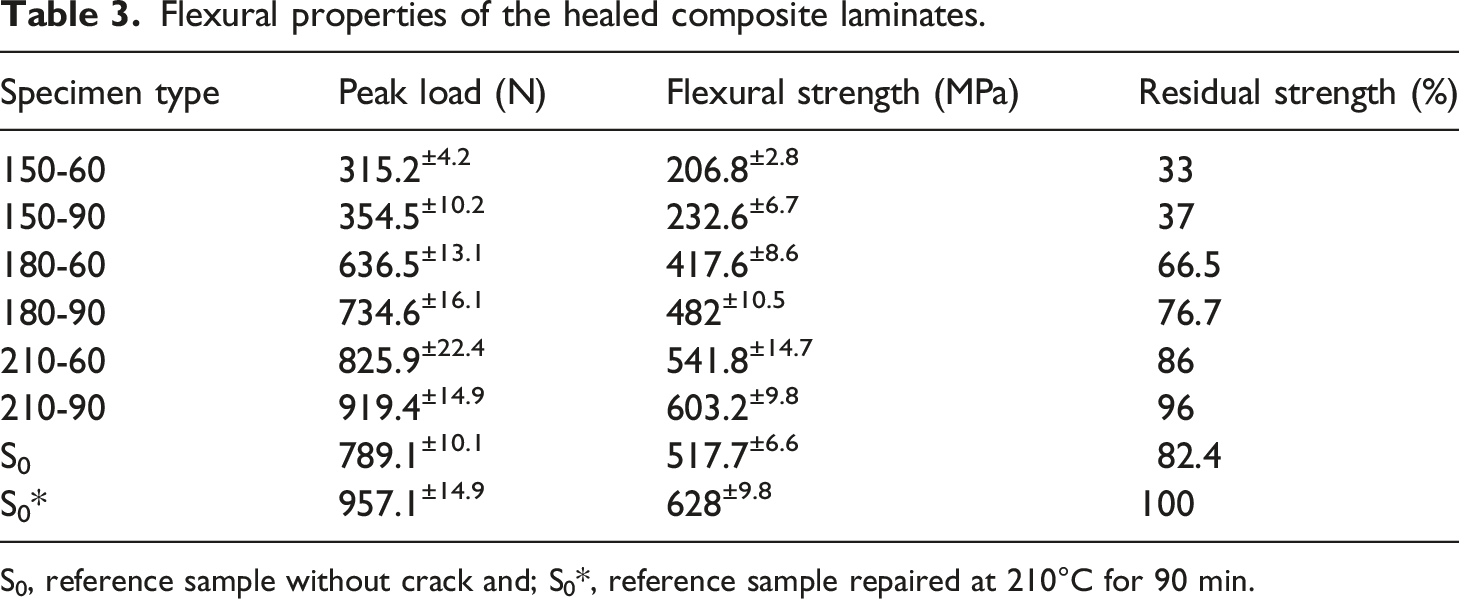
A comparison of the results reveals that the S0 specimens without any cracks show lower average flexural strengths and peak loads than the S210-90 and S210-60 healed specimens. As discussed in the XCT analysis section, the lower values for the S0 specimens are associated with a lower fiber volume fraction compared to that of the healed specimens. The load versus displacement curves for S0 and S0* specimens are shown in Figure 8(b).
The results in Table 3 and Figure 8(b) reveal that subjecting the S0 specimens to the optimum healing parameters results in substantial increase in their mechanical performance. In fact, as expected,S0* the specimens exhibit higher flexural strengths and peak load values compared to all of the healed specimens. This increase is also associated with an increase in the fiber volume fraction of S0* specimens after the healing process. The load versus displacement curves in Figure 8 show that the S0 specimens exhibit a progressive failure mode with zigzag patterns in the load versus displacement curves after reaching the peak load. In contrast, all of the healed specimens demonstrate an abrupt failure mode, involving a significant drop in load after the peak value. A post-failure examination highlights different failure modes in the two types of specimen (Figure 9). Failure modes in (a) a reference specimen (S0) and (b) a specimen healed at 210°C for 90 min (S210-90).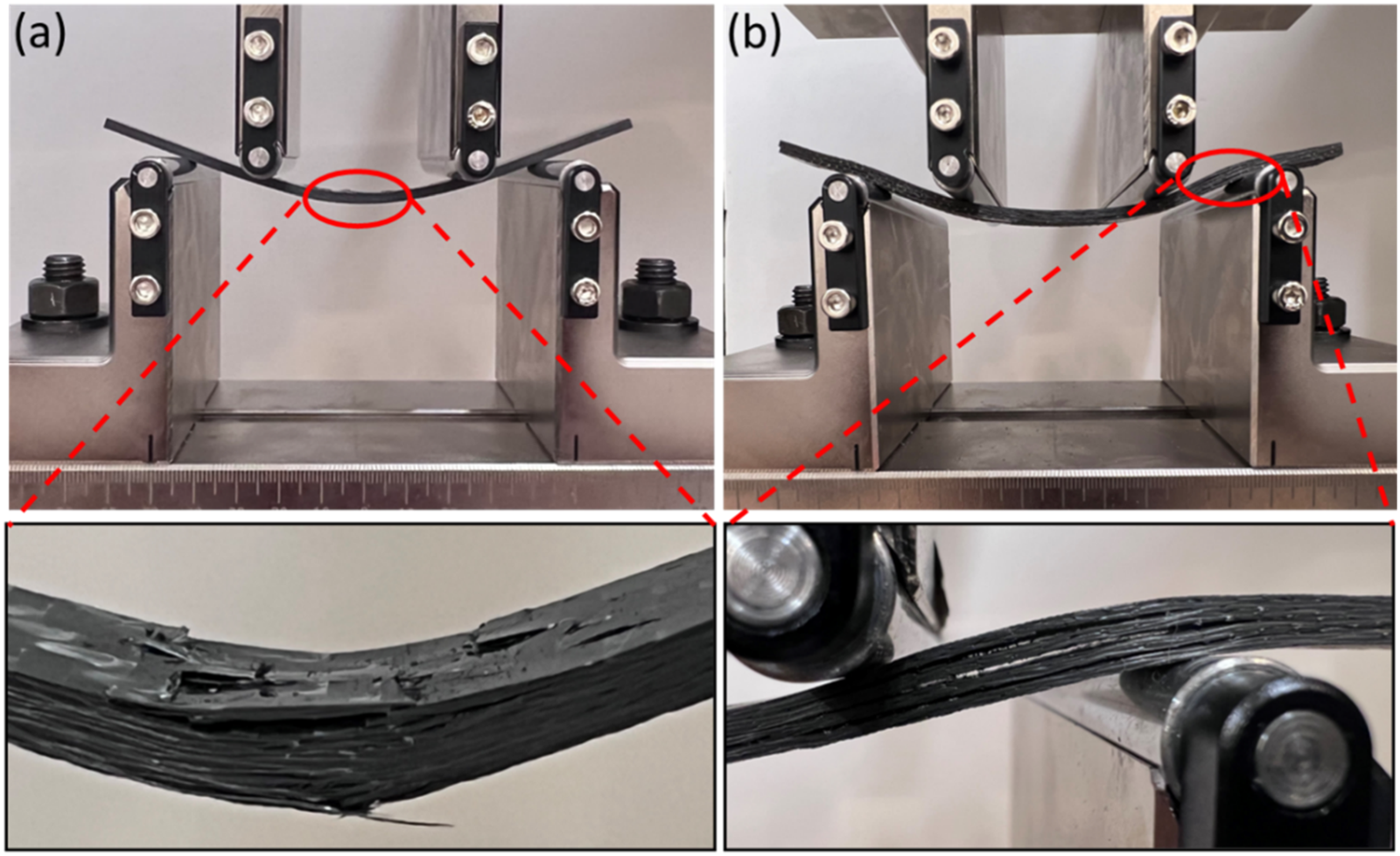
Thermo-mechanical properties of reference composite laminates.
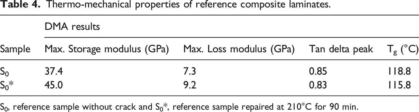
S0, reference sample without crack and S0*, reference sample repaired at 210°C for 90 min.
It is important to note that the S210-60 and S210-90 specimens show significantly higher flexural strengths than the reference specimen (S0). Apart from an increase in the fiber volume fraction of the healed specimens, this increase in flexural strength can also be attributed to the effect of heat treatment. A number of previous studies have reported that the heat treatment of PMMA polymers can improve their mechanical performance. For example, Kawaguchi et al. 53 investigated the effect of heat treatment on the flexural performance of PMMA by conducting three-point bending tests before and after heat treating the specimens at 130°C. A significant increase in the flexural strength as well as the flexural modulus was observed as a result of this heat treatment cycle. Additionally, the surface microhardness of PMMA polymer was also increased following heat treatment. In a similar study, Avila et al. 54 reported an increase in the tensile strength of PMMA, PEEK and polycarbonate (PC) specimens following heat treatment.
Given that the healed crack appears to fail in an opening mode at the crack trip, the residual strength of the healed composite laminates is compared with their Mode I fracture toughness (GIc) determined through DCB tests, as reported in our previous study.
2
The residual strength is plotted against its corresponding GIc value in Figure 10. The figure reveals a linear increase in the residual strength as the fracture toughness of the specimens is increased. Additionally, analysis of variance (ANOVA) approach previously revealed that the applied temperature was the most dominant parameter during bonding of these laminates, having 82% contribution towards the interlaminar fracture toughness.
2
In addition, both the fracture toughness and the residual strength increase by increasing the healing time. These results also confirm that the optimum outcomes for both cases are achieved using the same healing parameters that is, 210°C and 90 min (or for the S210-90 specimen). It is also observed from the thermogravimetric analysis (TGA) that a further increase in both temperature and healing time results in the degradation of the thermoplastic resin, hence, in the mechanical performance.
2
Therefore, the healing temperature and healing time are not increased beyond 210°C and 90 min., respectively. Residual strength as a function of the Mode I fracture toughness for specimens healed for (a) 60 min and (b) 90 min.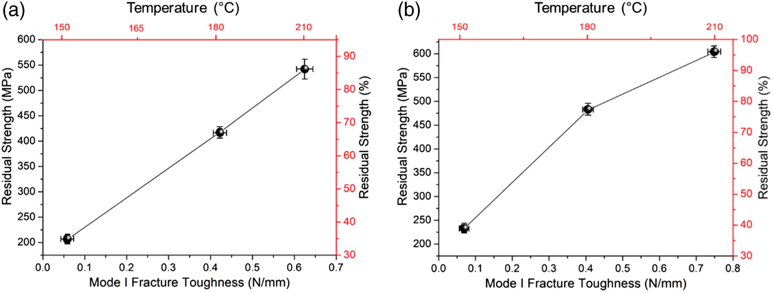
Dynamic mechanical analysis
A series of DMA tests are conducted to confirm the enhancement in the strength of S0 specimens after being subjected to the optimum healing parameters. The storage moduli curves for the two types of specimen over a range of 30–150°C are presented in Figure 11(a) and the loss moduli and tan delta curves are presented in Figure 11(b) and (c), respectively. The average maximum values of all these parameters are calculated from the respective curves and are listed in Table 4. Figure 11(a) shows that the storage modulus exhibits a gradual decrease for both types of specimen prior to the onset of Tg. Once the temperature is increased beyond the Tg of the polymer, a dramatic decrease in the storage moduli is observed, following the transition from a glassy state to a rubbery state. Clearly, the highest values of storage moduli are recorded in the glassy state as the molecules are densely packed and experience strong intermolecular forces compared to the rubbery state.
55
Dynamic mechanical analysis of the reference specimens (a) storage modulus, (b) loss modulus and (c) tan delta.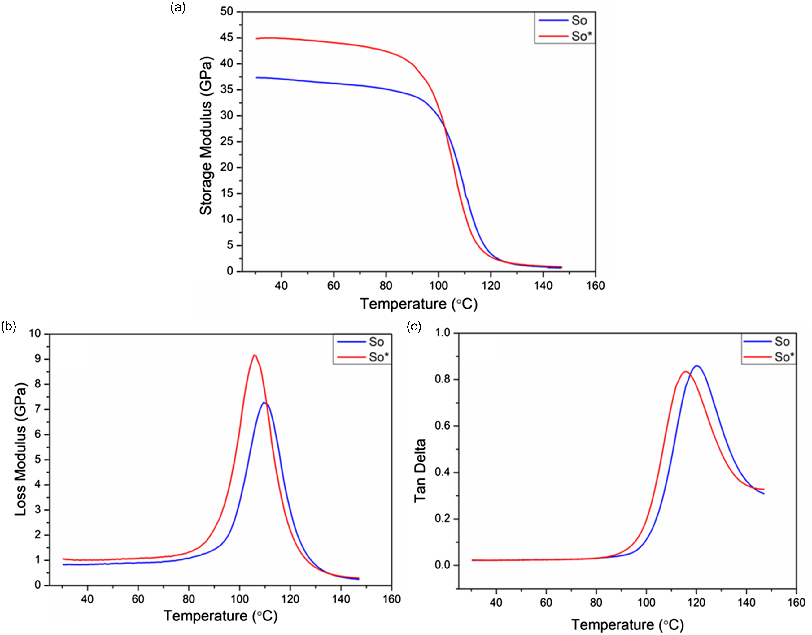
The results also show a significant increase in the stiffness of the S0* samples after subjecting them to the optimum healing parameters. The average value of the maximum storage modulus for S0* samples is increased from 37.4 GPa to 45.0 GPa. As discussed in the Flexural tests section, this increase is associated with an increase in the fiber volume fraction of the S0* specimens. Similarly, the peak value of the loss modulus of the specimens is also increased from the 7.3 GPa to 9.3 GPa. The Tg for both types of specimen is calculated from the peak value in the tan delta curves. In terms of glass transition, the Tg of the S0* specimens is found to be lower than that of the S0 specimens. In general, the glass transition is primarily influenced by the fabric type and the applied frequency. 56 As the applied frequency and fabric type are the same for both types of specimen, the reduction in the Tg of the S0* specimens can be related to thickness variations in both types of sample. It has been reported in the literature that an in increase in the thickness of a polymer sample could result in a significant increase in its Tg. 57 Therefore, a decrease in the overall thickness of the S0* specimens after the healing process appears to have resulted in a decrease in the Tg.
Microscopic analyses
Optical microscopy
Cross-sectional optical micrographs of the cracked specimens before and after healing using different processing parameters are shown in Figure 12. These micrographs are used to identify the defects associated with the introduction of the artificial cracks as well as the morphological changes associated with different healing parameters. Cross-sectional micrographs of the reference specimen (S0) without any cracks reveal no visible defects or micro-voids. However, Figure 12(c) shows that introducing artificial cracks in the composite laminates results in porosity and micro-voids. It is important to note that inserting three nylon sheets as separation layers within the preform to create artificial defects provides resistance to through-thickness resin flow during the infusion process. Along with this, another contributing factor towards the occurrence of these defects is inability to de-gas the liquid thermoplastic resin. Conventional thermosetting resins are de-gassed prior to resin infusion in order to remove microbubbles and dissolved gases. However, according to the manufacturer, Elium® resin cannot be de-gassed as it bubbles up more.
58
As a result, the through-thickness resistance to resin flow and lack of de-gassing, randomly distributed micro voids are observed around the crack sites in the artificially cracked specimens. In contrast, Figure 12(a) demonstrates that the reference specimens have a high quality without any visible defects. Cross-sectional optical micrographs of (a) fully infused reference specimens, (b, c) artificially-cracked specimens before healing, and (d–i) specimens healed at different parameters.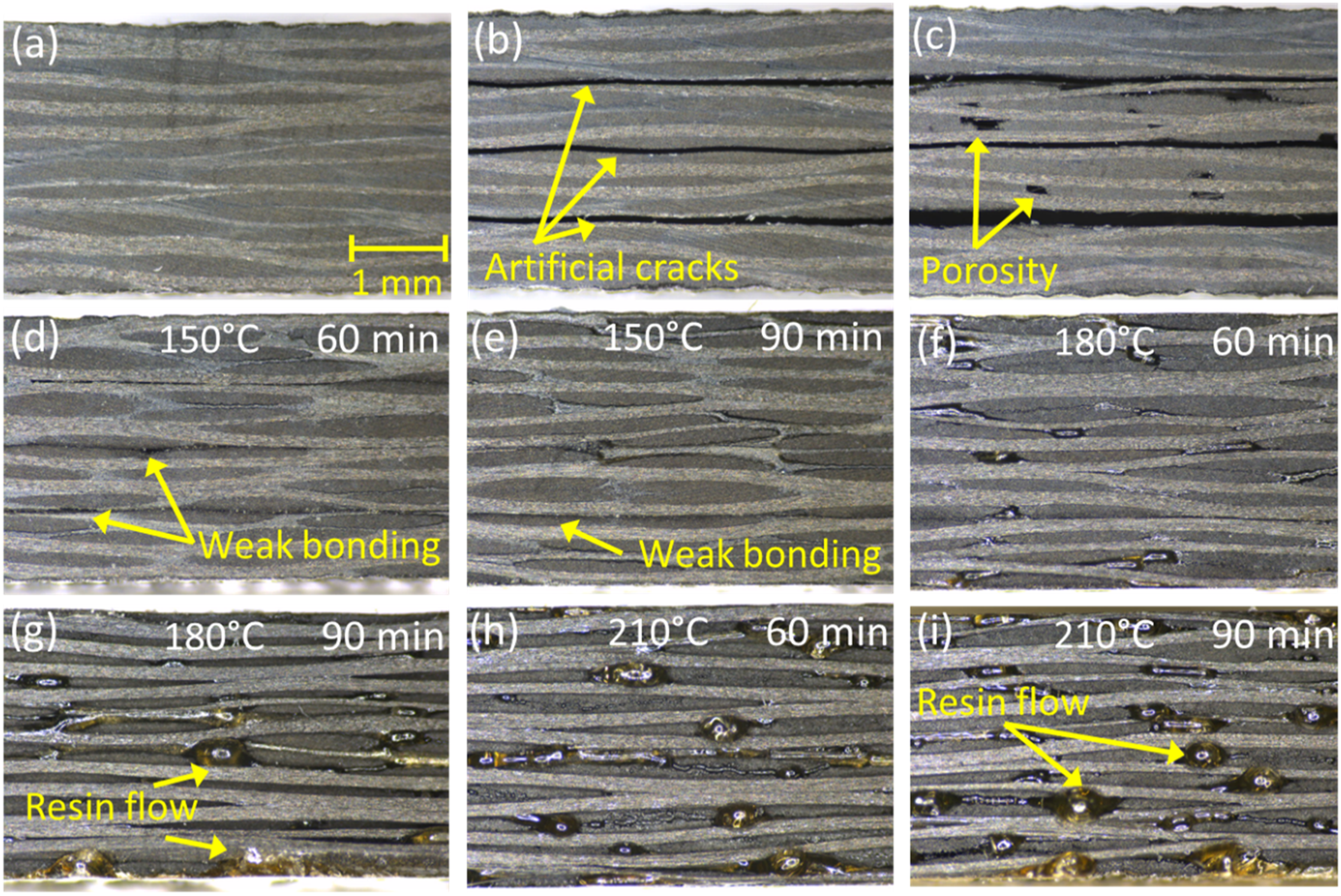
Cross-sections of pre-cracked specimens healed at 150°C for 60 and 90 min are shown in Figure 12(d) and (e), respectively. It is clear the due to weak bonding; the cracks are not fully healed at this temperature. Even though 150°C is well above the Tg of the Elium® resin, there is insufficient reptation of polymer chains across the interface, hence, no visible resin flow is observed. Nevertheless, an increase in the contact time at 150°C results in an improvement in the level of repair. It is important to note that Elium® is a polymethyl methacrylic (PMMA) based liquid resin that undergoes radical polymerization at ambient temperature, initiated by the reaction of the peroxide hardener with the monomer (i.e. methyl methacrylic (MMA)). 59 Therefore, Elium® resin does not exhibit a distinct melting point. However, PMMA demonstrates a fluid-like behavior and tends to flow at temperatures well above the Tg.60,61
A further increase in temperature from 150°C to 180°C reveals significant polymer flow throughout the specimen, as shown in Figure 12(f) and (g). Indeed, the cracks are observed to be fully healed at 180°C following a contact time of 90 min. The healing process is initiated by the reptation of the polymeric chains at a microscopic level. Along with this, macroscopic polymer flow also contributes to the complete healing of the artificial cracks at higher temperatures. 2 Increasing the repair temperature from 180°C to 210°C increases the molecular diffusion process throughout the specimens, especially across individual crack interfaces. As a result, the original cracks completely disappears, exhibiting uniform and fully healed interfaces. A number of studies have been reported in the literature, focusing on other thermoplastics such as, polystyrene and PEEK, where the mechanical performance of the specimens has been observed to increase exponentially with self-bonding temperature.62,63 It has been well established that polymer chains are more mobile at higher temperatures and exhibit clear diffusion across the crack interface, leading to a superior bond strength. 63
Scanning electron microscopy
Scanning electron microscopy images are used to elucidate the failure mechanisms in the reference and the healed specimens subjected to flexural loading. Additionally, the SEM images are also helpful in understanding the healing mechanisms, in terms of resin flow across the crack interfaces and fiber-matrix interface on a microscopic level. The SEM images of the fractured S0 specimens and S150-90 specimens are shown in Figure 13. In general, the S0 specimens exhibit the typical brittle failure mode frequently observed in CFRP laminates, due to strong fiber-matrix interface.
56
Apart from brittle fracture, individual carbon fibers are also pulled out from the fractured region during the final stages of flexural loading, as shown in Figure 9(a). In addition, resin damage and river line patterns are observed to be dominant failure modes in the S0 specimens. For the healed laminates, the S150-90 specimens exhibit weak bonding at the healed interfaces and as a result, a delamination-type of failure mode is more prominent in these specimens (Figure 13(e)). Additionally, the delaminated surfaces exhibit a weaker fiber-matrix interface due to inadequate bonding (Figure 13(f)), as confirmed by the optical micrographs in Figure 12(d) and (f). Even though, delamination is the primary cause of failure in all the healed specimens, the SEM images also reveal fiber fracture and debonding failure modes in these specimens. It is worth mentioning that the specimens healed for 60 min. at three different temperatures (i.e. 150, 180 and 210°C) show similar failure modes, as observed in specimens healed for 90 min. at these temperatures. Therefore, only the SEM images for the specimens healed for 90 min. and different healing temperatures are shown in Figures 13 and 14. SEM images of the fractured specimens (a–c) reference specimen (S0) and (d–f) specimen healed at 150°C for 90 min. SEM images of the fractured specimens (a–c) specimen healed at 180°C for 90 min and (d–f) specimen healed at 210°C for 90 min.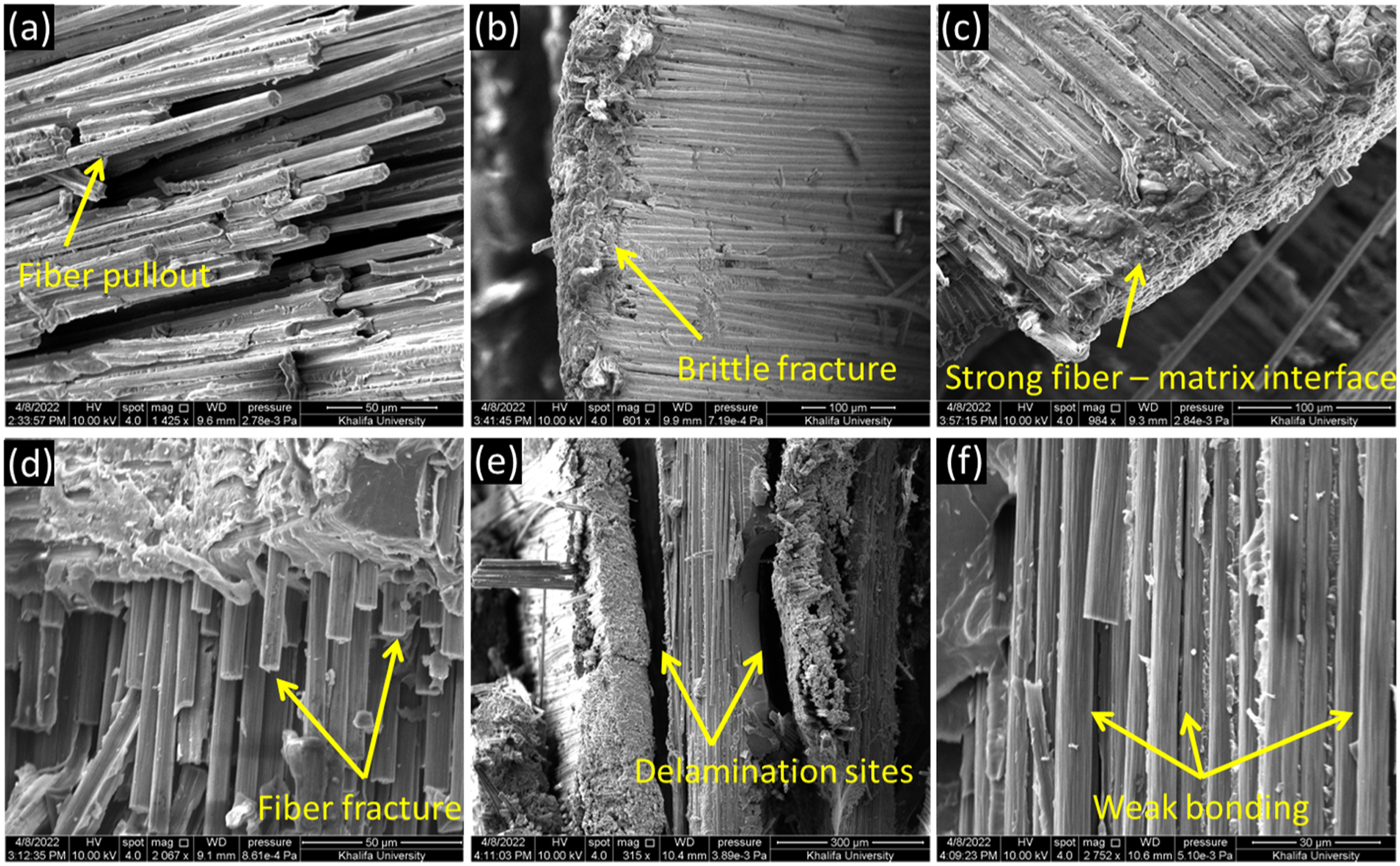
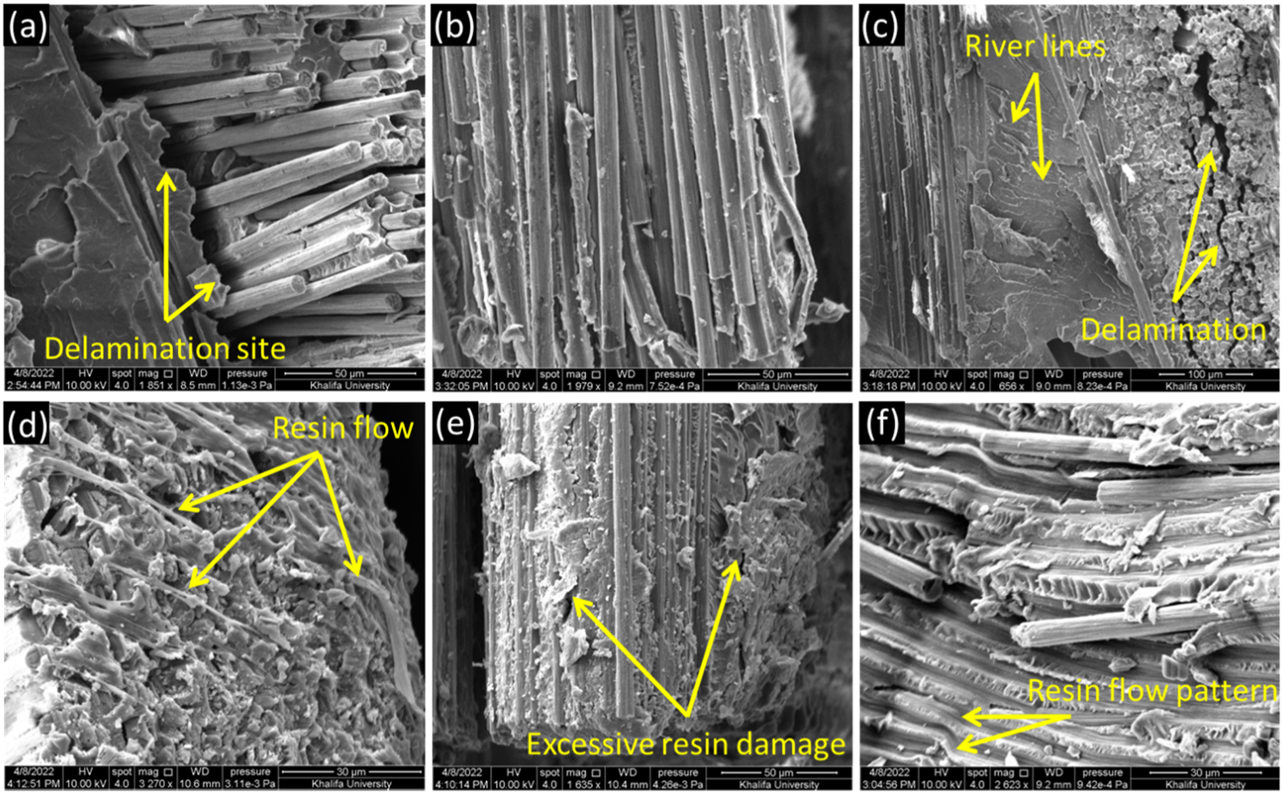
As observed from the optical micrographs in Figure 12, an increase in the healing temperature significantly improves the degree of bonding between the crack interfaces. As a result, the mechanical performance of the healed specimens is also improved. The SEM images of S180-90 specimens reveals excessive resin damage in the form of river lines due to superior bonding compared to the S150-90 specimens. However, the primary failure mechanism in S180-60 and S180-90 specimens is also observed to be delamination. The fibers are also pulled out from the delamination or crack interface sites upon failure and the cracked surfaces show weaker fiber-matrix adhesion. A further increase in the healing temperature to 210°C results in a dramatic change in the morphology of the cracked samples. As observed through the optical micrographs (Figure 3(h) and (i)) and the XCT images (Figure 5(b) and (d)), the cracks are fully healed, due to resin flow across each crack interface at 210°C. This resin flow can be seen in the SEM images of the fractured S210-90 specimens (Figure 14(d)). The thermoplastic resin is observed to flow throughout the specimen, resulting in stronger bonding between the carbon fiber and the matrix. In fact, the SEM images also highlight the resin flow pattern in the fractured specimens after the fibers are pulled out (Figure 14(f)). Along with this, excessive resin damage is observed in the S210-90 specimens, due to the stronger fiber-matrix interface. In summary, the SEM images support the optical microscopic and XCT analysis observations and provide a clearer understanding of the healing mechanisms at a microscopic level.
Conclusions
In this research, artificially cracked carbon fiber/Elium® composites, containing defects depicting impact-induced delamination were manufactured using the VARTM technique and subsequently healed under different conditions. The quality of the healed laminates was investigated using optical microscopy and an XCT analysis. The raw XCT images were used to create 3D models for an in-depth analysis of the healing mechanisms, based on the interdiffusion of polymeric chains and macroscopic resin flow across the crack interfaces. The mechanical performance and the bonding quality of the healed laminates was evaluated through four-point bending tests, whereas the failure modes were investigated through an SEM investigation.
The cross-sectional micrographs and the XCT images revealed that as the healing temperature was increased, the artificial cracks began to disappear until they were fully healed. The optimum healing temperature was found to be 210°C. A statistical analysis based on the 3D models generated from raw XCT images showed that the SVF increased from 47% to 70% after healing using the optimum parameters (210°C, 90 min and 200 kPa). As a result, the flexural strength of the healed samples was found to be higher than the reference specimens without any cracks. However, subjecting the reference specimens to the optimum healing parameters increased their flexural strength from 517 MPa to 628 MPa and the storage modulus by over 20%. The residual strength of the healed specimens was up to 96% that of the reference specimens subjected to the same healing parameters. The SEM images confirmed that delamination from crack interfaces was the most dominant failure mode in the healed samples in contrast to fiber fracture and brittle failure in the reference specimens.
Footnotes
Acknowledgements
The authors are thankful to Arkema, China for providing the Elium® resin.
Declaration of conflicting interests
The author(s) declared no potential conflicts of interest with respect to the research, authorship, and/or publication of this article.
Funding
The author(s) disclosed receipt of the following financial support for the research, authorship, and/or publication of this article: This publication is based on the work supported by Khalifa University of Science and Technology internal grant CIRA-2020-007.