
Abstract
Lightweight hybrid structures are developing these days due to increased demand for fuel economy and lower emissions in the automotive and aerospace industries. This study aims to analyse and optimise the influence of friction stir welding (FSW) process parameters on the tensile shear strength of the aluminium-polyamide hybrid joint. The study on the influence of each parameter on the joint strength helps define the bonding mechanism while joining aluminium-polymer hybrid structures. Optical microscopy and scanning electron microscopy (SEM) were used for microstructural examination. A SEM image of the weld’s cross-sectional area shows micro and macro mechanical interlocks with a small interfacial gap which indicates better joint strength. An elemental area mapping investigation of the weld zone reveals fine polymer and aluminium mixing along the interaction region. In addition, FSW parameters have been optimized to maximize the tensile shear strength of aluminium-polyamide hybrid joints. A mathematical model for tensile shear strength in terms of FSW parameters is developed using response surface methodology (RSM). A predictive model was developed using an Artificial Neural Network (ANN) to validate RSM predicted results. The analysis of variance (ANOVA) shows that the actual and predicted values have a satisfactory correlation. ANN methods are better than regression models in predicting tensile shear strength within input welding parameter ranges. The process variables were optimised using the desirability function analysis. The maximum joint tensile shear strength of about 19.74 MPa and attained at optimal FSW parameters, i.e. rotational tool speed of 1421 r/min, welding speed of 27 mm/min, and tool tilt angle of 1°. The regression coefficient for the ANN model was 0.988 for the test data set, indicating that the developed model is appropriate for predicting tensile shear strength.
Keywords
Introduction
The higher demand for lightweight materials keeps increasing due to the emission of CO2 and fuel price hikes in transportation industries like automotive, aerospace, etc.1,2 The development of hybrid metal-polymer structures improves the flexibility in the design and utilisation of materials from an object perspective. 3 The developments in joining hybrid structures using polymers and metals provide desirable and unique material features like improved strength and stiffness, resistance to physical damage caused by fractures, radiation resistance, and design flexibility. Metals and polymer combinations are widely used in aerospace and automotive components, electrical equipment, etc.4,5 Thermoplastics are used in engineering and industrial application due to lesser weight, higher specific strength, good modulus of elasticity, design flexibility, and lower production costs.6–8 Aluminium (Al) and Magnesium (Mg) have recently been used to replace traditional steels in various industries, including automotive, aerospace, railway, and shipbuilding. 9 Polymer/metal hybrids are now utilised for indoor automotive components, instrument clusters, cross-beams structures, tailgates, and other applications ranging from household appliances to bicycle frames. 2
The conventional methods of joining hybrid metal-polymer joining are adhesive joining and mechanical fastening. Adhesive joints need unique surface treatments for improved strength properties and are subjected to high processing time and low operating temperatures. Mechanical fastening has advantages like easy repairability and flexibility, but fasteners like bolts or rivets cause an increase in the weight of structures. Some current methods adopted for joining metal-polymer include ultrasonic welding and laser welding. Ultrasonic welding of metal to composites is possible, but it has limitations in that it can be applied to thin plates. The problem with laser welding is bubble formation due to the heat, which degrades the polymer. The heat develops during welding due to the melting temperature of metal and polymer; there is a chance of a softer polymer to degrade or oxidise.2,10 It is possible to employ a solid-state welding process to resolve such technical issues. The FSW technique can be adopted where frictional forces plasticise the base materials until they become plastically deformed, and then they are stirred and mixed by the rotating force of the tool. 11
The concepts of frictional heating and plastic deformation are combined in FSW, a cutting-edge solid-state joining method in which a thermomechanical way is used to plasticize materials.12–16 The stirring results in mixing, and later a joint is developed at a temperature below the melting point of the base materials. 17 Thus, FSW is a better joining process for decreasing distortions and residual stresses that affect traditional welding processes. In addition, the process parameters substantially influence microstructural development, mechanical characteristics, and thermal distribution, resulting in many potential performances. 18
The impact of heat input on FSW of AA5052 with polypropylene in lap configuration was investigated by Shahmiri et al. (2016). Aluminium 5052 is joined with polypropylene employing an aluminium plate as a cover to regulate polymer flow. The tapered threaded tool with a shoulder diameter of 20 mm, a pin length of 3.5 mm, a larger diameter of pin is 4.5 mm, and a smaller diameter of pin is 2.5 mm. A strong joint with a tensile strength of 5.1 MPa is attained. 5 Wang et al. (2021) did laser surface texturing between the joining partners while FSW of aluminium 6061and polyamide. The surface texturing shows significant improvement in joint strength by enhanced mechanical interlocking. 19 Elahi et al. (2021) performed laser welding of aluminium 1020 and polyamide by introducing surface textures to the aluminium surface in order to increase the mechanical strength of the joint. It is observed that with the formation of an aluminium oxide layer as a result of laser surface treatments, the adhesion between the surfaces improved. 20 Andre et al. (2018) studied the friction spot joining between aluminium 2024-T3 and carbon fibre-reinforced-poly-phenylene-sulphide (CF-PPS) using an additional PPS interlayer. The finding from the study suggests that a minimal interlayer thickness gives better enhancement in joint strength. 21 Sun et al. (2021) investigated a novel thermal-assisted FSW technique for joining Aluminium 6061 and polycarbonate. The thermal techniques show improvement in weld surface appearance and joint strength. 22 Mirhashemi et al. (2021) studied the effect of silicon carbide nano reinforcement while FSW of low-density polyethylene and aluminium 7075. The study shows significant enhancement in strength as well as the hardness of the hybrid joint. 17 Ratanathavorn et al. (2015) studied the friction stir lap joining of aluminium 6111 and polyphenylene sulphide. A threaded cylindrical tool with a pin diameter of 4 mm and a 15 mm diameter wiper shoulder with a length of 2.7 mm was used. The study focuses on the effect of translational speed, rotational speed, and backing distance on the strength of the joint, and failure mode was also analysed. 23 Huang et al. (2018) did FSW using a triple facet tool to join short fibre-reinforced polyether-ether-ketone with AA2060 and AA6061. Using both stationary and moving shoulders, as well as a plunging tool pin with three faces, promoted mechanical interlocking between the welded hybrid joints. 24 Derazkola et al. (2019) examined the effect of FSW process parameters on strength and hardness while welding aluminium 5754 poly-methyl-meth-acrylate in T joint configuration. The thickness of the interaction layer and the generation of inner voids have a significant impact on the strength and hardness of the joint. 11 Liu et al. (2014) investigated the effect of process variables on the formation of bubble-like defects during friction lap welding of AZB-31 Mg alloy and polyamide. The finding shows that a significant increase in welding speed, rotational tool speed, and plunge depth can reduce defects like bubble formation. 25 There lot of studies happened in joining of metal polymer hybrid structures with variation of welding process parameters, Tool profile modifications, surface modifications, effect of interlayer etc. There are minimal studies were done using statistical tools to study the effect of process parameters and optimization on FSW of metal polymer hybrid structures.
This study is significant since minimal work is done on joining hybrid metal-polymer structures using FSW, and no work is reported on the joining of aluminium 5754 to Polyamide. Studies have been done using different joining techniques on aluminium and polymer.20,26–28 Several works were done on FSW of aluminium 5754 (metal to metal) as well as polyamide (polymer to polymer) with different metals as well as polymer with other combinations.29–33 The hybrid aluminium-polyamide structure could serve as an alternative for automotive interior panel components. Only limited optimisation studies are done on the influence of process parameters on the FSW of metal-polymer hybrid joints.
34
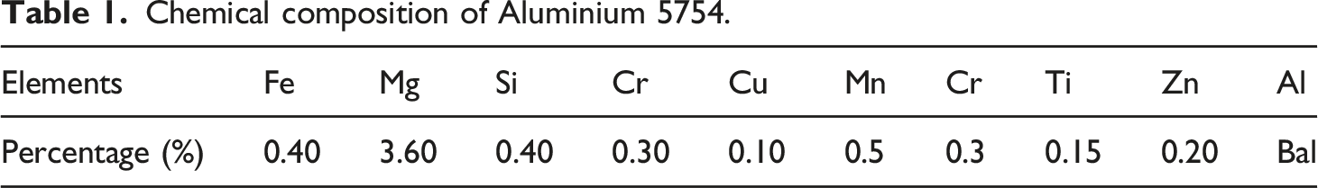
The work focuses on optimising FSW parameters for enhancing the joint strength of aluminium 5754-polyamide hybrid joints. Then efforts are also made to reveal the bonding mechanism of the joint by microstructural analysis. However, a comprehensive study is necessary to optimise and analyse the influence of welding variables on shear tensile strength using RSM. This study uses the ANN design to establish an adequate simulation model for predicting, monitoring, and regulating the mechanical properties of aluminium-polyamide welding based on FSW process parameters. The methodology adopted for the investigation is shown in Figure 1. The experimental case results have been used as data set for training, testing, and validating the ANN. The model displays accurate and consistent results. As a result, a model is a promising tool for evaluating the tensile strength of the proposed aluminium-polymer hybrid structure. Methodology. Chemical composition of Aluminium 5754.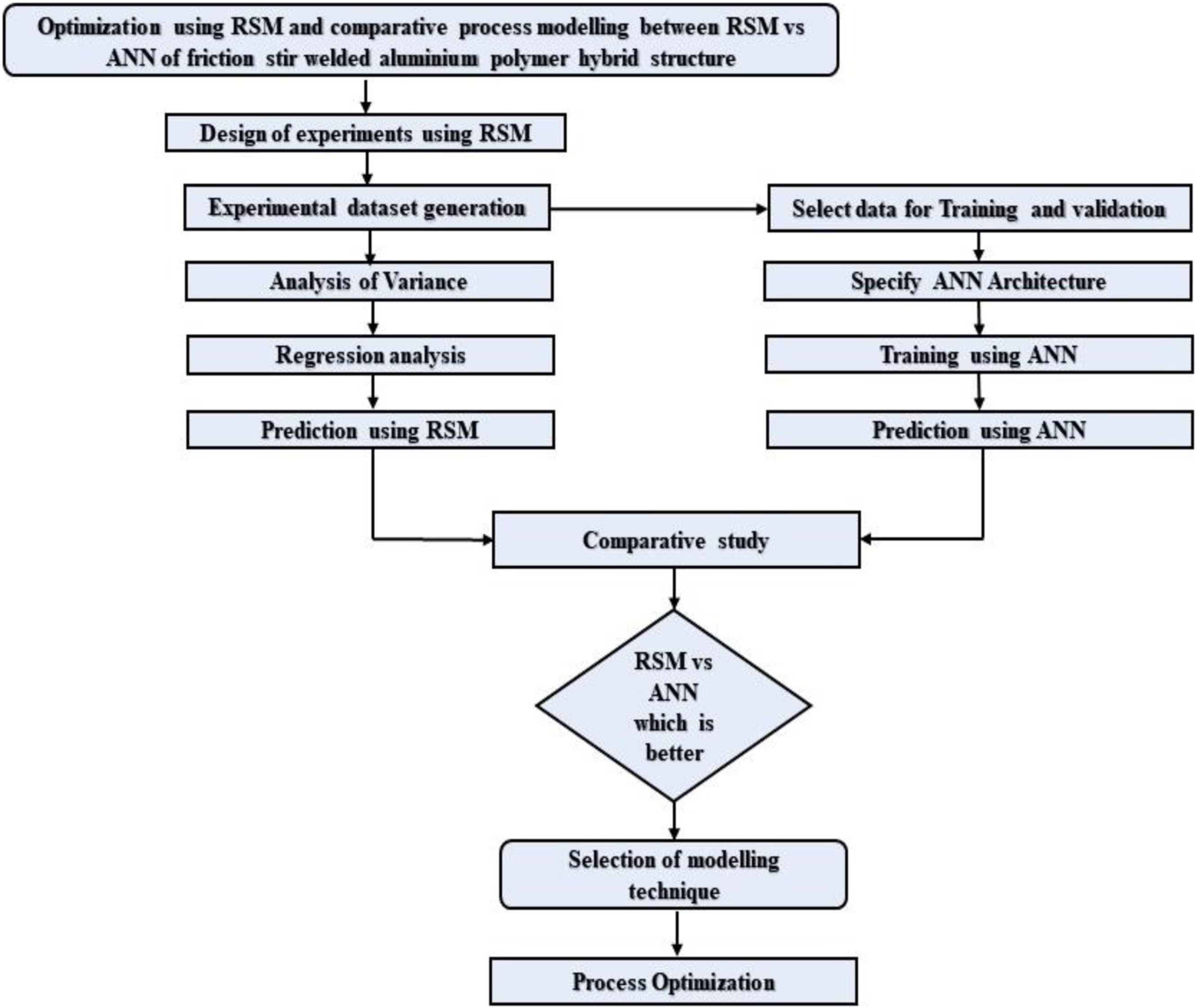
Experimental procedure
Base materials
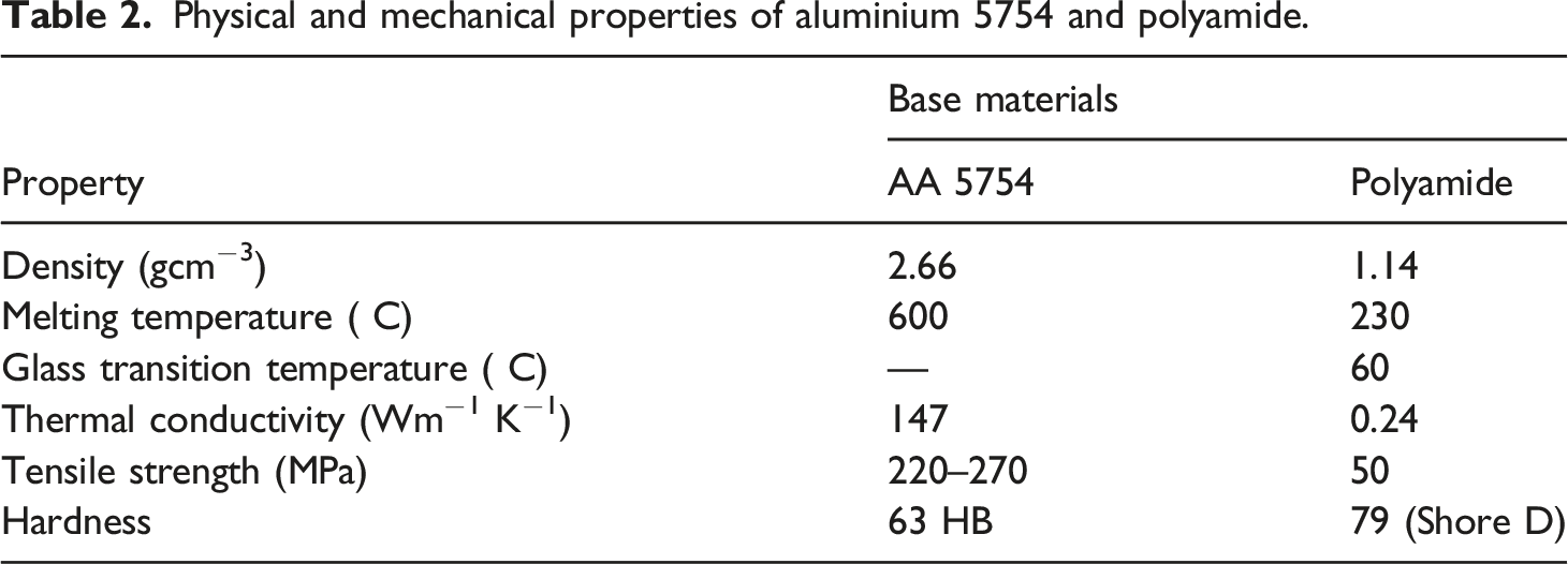
Physical and mechanical properties of aluminium 5754 and polyamide.
Friction stir welding
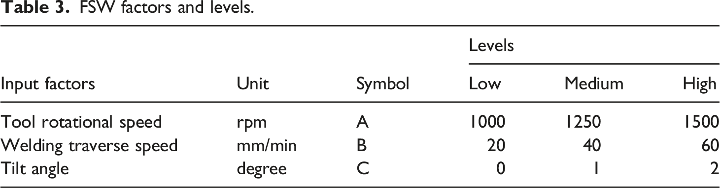
The workpieces were joined in the lap joint configuration in a numerically controlled friction stir welding machine by R.V. machine tools (Model 380–440 V/400A) with a maximum axial load of 30 kN capacity, rotational tool speed of 3000 r/min, and weld transverse speed of 1000 mm/min. The FSW setup used for experimentation is shown in Figure 2. Aluminium 5754 is placed over the polyamide in lap joint configuration to enhance frictional heat and prevent the overflowing of polymer. An overlap width of 30 mm is used for the lap joint. In this investigation, the tool material chosen was H13 tool steel with a threaded tapered pin. The interruption in tapered threaded tool pin profile improves contact area, and better mixing of material happens, hence better joint strength. The tool has a diameter of shoulder 15 mm, with a tapered threaded pin of taper angle of 3° with a length of 4 mm, with a larger diameter and smaller diameter of pin is 5 mm, and 3 mm. The thread of the tool has 0.5 mm pitch and 0.5 mm depth. The welding parameter ranges were identified based on the trail welds performed on the Aluminium 5754 and polyamide combination. Three alternative levels of tool rotational speed (TRS), weld traverse speed (W.S.), and tool tilt angles (T.A.) were investigated in this work. Friction Stir welding Setup.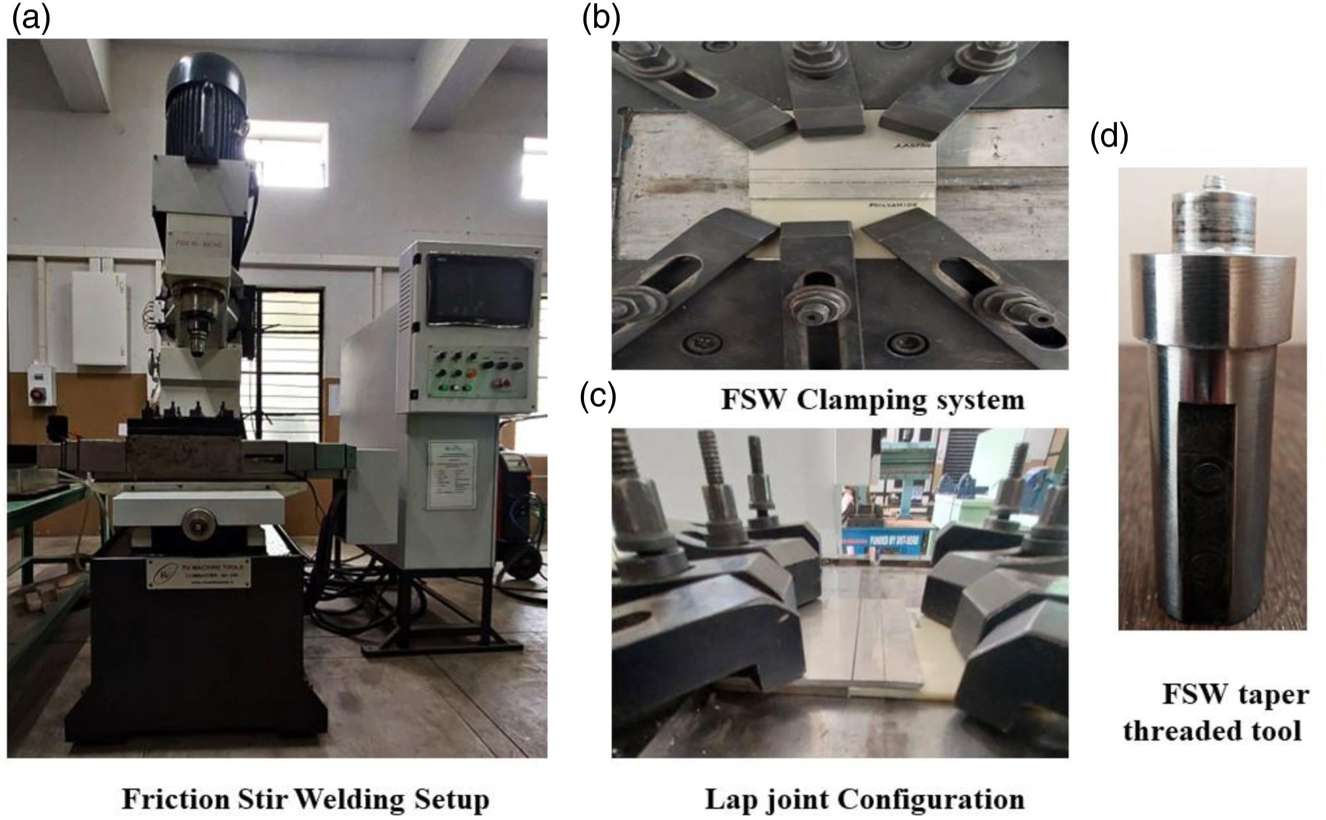
FSW factors and levels.
Experimental design using response surface methodology
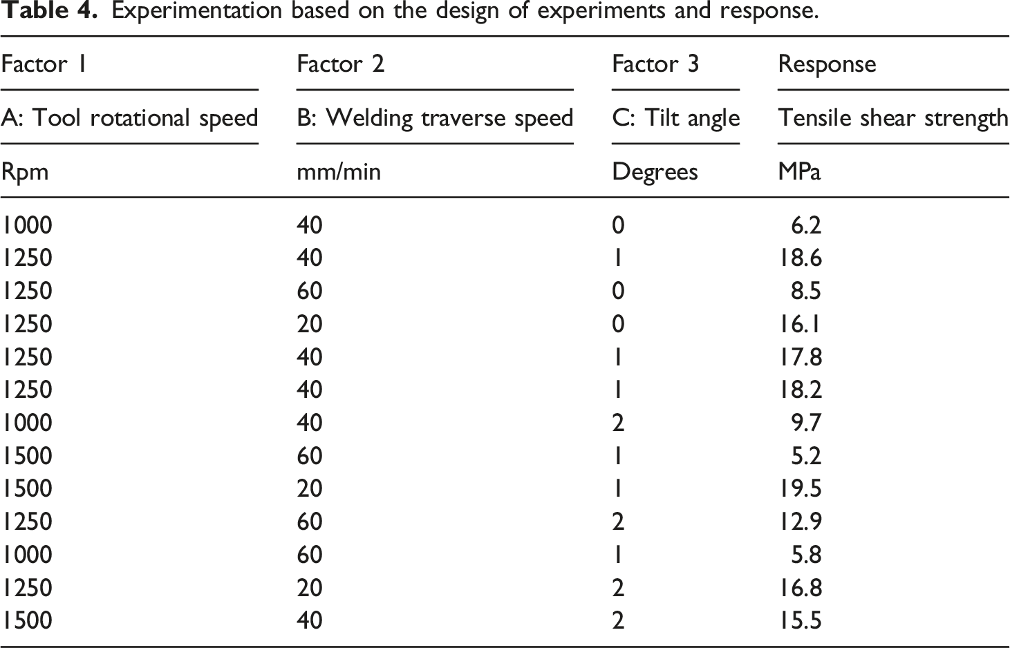
Experimentation based on the design of experiments and response.
Analysis of experimental data
A second-order polynomial equation represents the process, assuming that a quadratic regression model can predict the response variable, tensile strength. According to the design of experiments, the experimental results were loaded into the software, represented as a quadratic model, the best-fitted model for forecasting the optimum combination of input parameters for obtaining the maximum tensile shear strength. The input and output values of the experiments are tabulated, and a regression model is developed.
In equation (1), q is the number of process variables, and β0 and βi are the coefficients of the linear, quadratic, and interaction factors.
The full quadratic model was evaluated using ANOVA at the 95% confidence level to check whether it was statistically significant. The accuracy and precision of the model depend upon the p-value and correlation coefficient. Based on these methodologies, the relationship would be significant within the confidence level if the computed value of the p-value for the generated model and their constants were smaller than the standard p-value (= 0.05). Finally, the model was used to forecast the optimal combination of elements that would result in the joint’s maximum tensile shear strength.
Experimental characterization
Tensile strength characterisation
Universal testing equipment (Instron 8801) is used to determine the quasi-static tensile shear strength of metal-polymer hybrid joints using tensile lap shear tests. The shear tensile sample of size 25.4 mm was prepared for testing according to ASTM D1002-05. The test samples for the tensile shear test were cut in a direction perpendicular to the welding using water jet machining. Figure 3 illustrates a schematic of the tensile sample for testing. The test was performed at room temperature with a speed of crosshead 0.5 mm/min. Three samples were examined for shear-tensile strength for each experimental set, and the average values for joint strength were given. Schematic of the tensile shear specimen.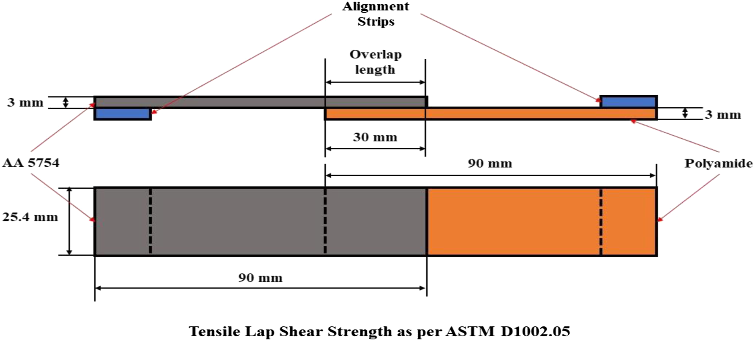
Metallographic studies
Visual inspections of weld beads and metallographic examinations were performed to understand material mixing and bonding mechanisms. Metallographic specimens were prepared using the standard metallographic method. The examination uses an optical microscope (O.M.) and SEM with energy dispersive X-ray spectroscopy (EDS) for weld sample cross-sections obtained at optimal conditions. Metallographic specimens were extracted in the direction perpendicular to welding using a slow-speed diamond saw, METCO Chennai. Emery sheet grades ranging from 200 to 2000 were used to achieve a polished finish on the metallographic specimens. The microstructures which are presented in this study were taken without etchants. Diamond paste is finally used to polish the sample to get a mirror-like surface finish. Finally, a thin gold sputter is applied over the weld cross-section to make it conductive while the SEM examination.
Microhardness studies
The microstructural samples were used for hardness examination as well. The change in hardness of the polyamide side inside and outside the stir zone was investigated using the Shore D hardness test. Vickers microhardness test was conducted to investigate the variation in hardness of the aluminium 5754 alloy inside and outside the stir zone due to welding. This study shows the effect of welding on the hardness of the base materials on the optimal experimental run.
Thermal analysis
Thermal analysis was conducted on the optimal experimental run by means of FLIR T-420 model thermal camera to estimate the peak temperature while joining process near the tool-workpiece interaction region. This study helps determine the optimal peak temperature while welding to avoid polymer degradation and to achieve better joint strength.
Artificial neural network architecture
The fundamental elements of the nervous system that absorb input and produce output using mathematics are called neurons. Before going through a non-linear function called the activation function, the input is often weighted and given a bias. The activation function is a sigmoid function. A neuron is represented mathematically in equation (2). φ is the activation function, while y is the output. The ith input and weight are represented by xi and wi, respectively; b is the bias, where y is the output.
The ANN comprises three layers, comprising an input, hidden, and output layer, and has one neuron since the ANN must predict one parameter. To evaluate the model’s resilience, input data points were split into two groups. For training the neural network, 70% of the data is chosen. The remaining data was split between test and validation sets at a 15% each ratio. The ideal number of neurons in the hidden layer is assessed using a trial-and-error approach. The Levenberg–Marquardt backpropagation approach was used to create the ANNs. Weights and biases are continuously changed in the Levenberg–Marquardt optimisation method to minimize the variance of predicted values from desired values. An efficient ANN should be able to predict train data points while avoiding overfitting. The output of the ANN depends on the number of neurons in the hidden layer, activation function, and learning process. The activation function in this study is a tangent sigmoid function proposed in equation 3.
The maximal tensile shear strength of a hybrid joint predicted by RSM in the best combination was also confirmed empirically using the MATLAB ANN toolbox. The overall performance of the ANN network was established using mean square error (MSE) measurements. In the hidden layer, the number of neurons is changed numerous times during the training phase to get the lowest MSE.
Results and discussions
Development of fitting and testing of models
The tensile strength variation ranged between 5.2 MPa and 19.5 MPa. A non-linear regression-based mathematical metamodel enables the development of a relationship between input and output variables. Based on testing data, the software suggested the quadratic model as the best-fitting model for predicting the optimum input factor combinations for maximum tensile strength. The developed mathematical model for output responses is shown in the equation 4 below, along with the calculated coefficient values for the various responses.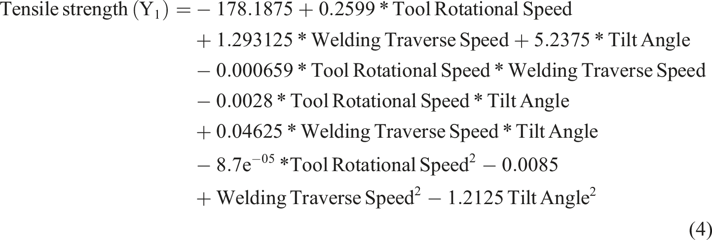
ANOVA analysis
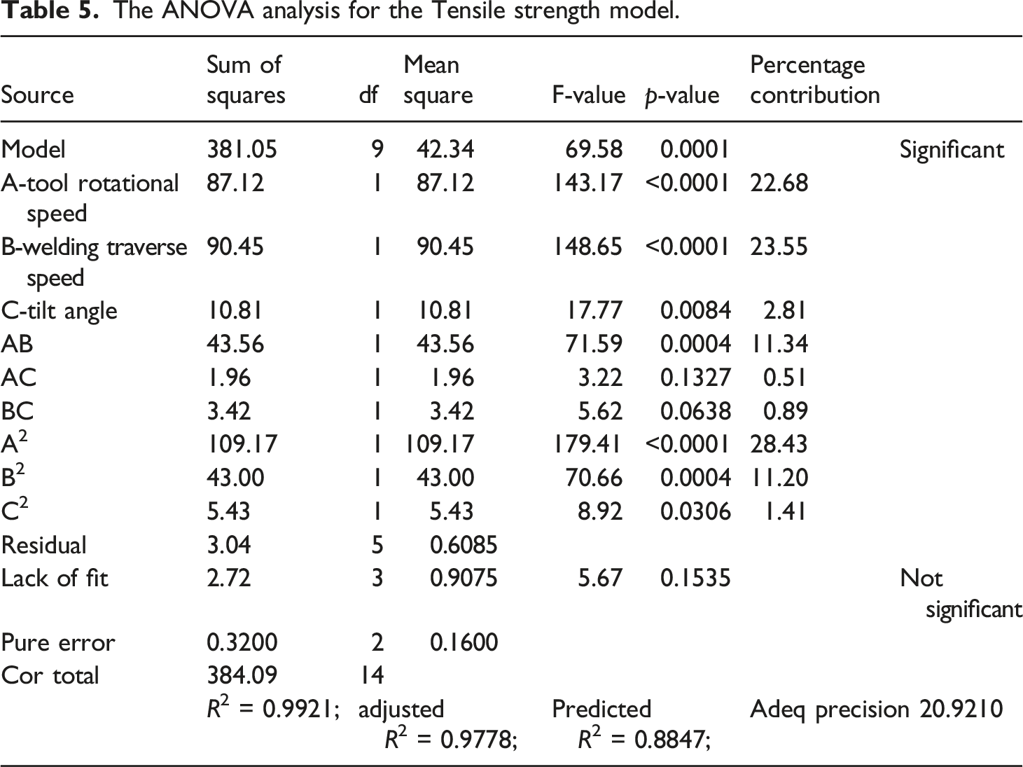
The ANOVA analysis for the Tensile strength model.
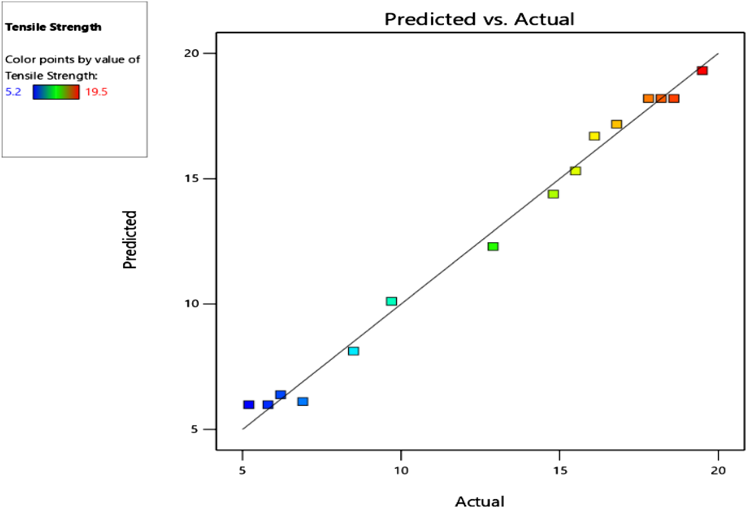
Correlation between observed and predicted values of Tensile strength.
Effect of interaction between input and output responses
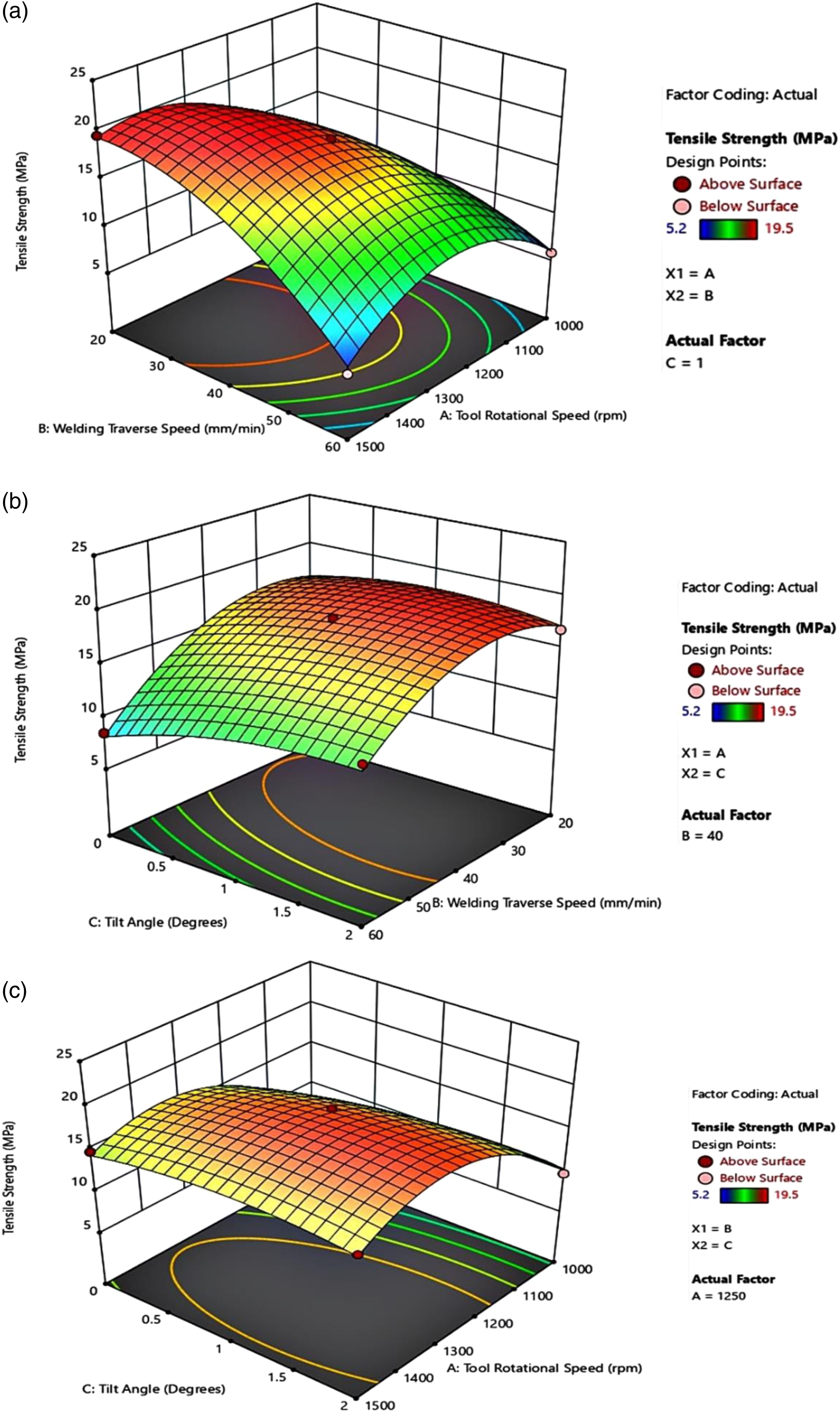
The perturbation plot in Figure 5 revealed that the most significant factors were welding traverse speed and tool rotational speed, followed by the slight effect of the tilt angle. Weld traverse speed and tool rotational speeds significantly affect the material plastic flow, primarily the heat generation. Figure 6(a)–(c) shows the influence of interaction factors on the shear tensile strength of a hybrid aluminium-polymer joint. The increase in welding speed has a detrimental impact on the tensile lap shear strength, as indicated in Figures 5, 6(a) and (b). With higher welding speed, the heat developed is less, so the temperature is insufficient for the proper stirring of materials. A similar trend of decrease in joint strength was observed while increasing the welding speed is reported in the previous literature.5,24 The joint strength increases with rotational speed, which can be confirmed in Figures 5, 6(a) and (c). Higher tensile strength is obtained due to excessive frictional heat produced at higher rotational speeds, which enhances mechanical stirring. At higher rotational speeds, the mechanical shearing of aluminium happens, and the developed heat tends to plasticize the polymer. During the stirring action, the metal fragment mixed well with the molten polymer to form a reinforced weld nugget. This reinforced weld nugget is a combination of a high amount of finer Al fragments and Polyamide, which enhances joint strength at a higher tool rotation speed. The heat developed due to friction at lower rotational speed is less, resulting in a smaller stir zone area, hence lesser strength. At lower speeds, shearing action gets minimized correspondingly, the amount of aluminium fragments in the stir zone gets reduced, and aluminium fragments are coarser. Less number of aluminium fragments results in lower tensile shear strength. At low rotational speed, frictional heat developed may not be sufficient for plasticizing metal as well as polymer. As the rotational speed increases, there is an enhancement in joint strength. The effect of tilt angle on the tensile shear strength is observed in Figures 5, 6(b) and (c). At a zero-tilt angle, there is insufficient vertical and horizontal material flow. As a result, increasing the tilt angle enhances the flow properties of the material by effectively filling into the defect, hence enhancing joint strength.
36
The optimum tilt angle is 1°, enabling the tool shoulder to envelop and transport deformed material from the front edge to the rear side of the pin. This effect results in improved weld performance in terms of tensile strength. Tensile shear strength of 39.48% of the base material is obtained. Perturbation plot for tensile strength. Response surface graphs of tensile strength (a) Tool Rotational speed and weld speed (b) tool rotational speed and tilt angle (c) welding speed and tilt angle.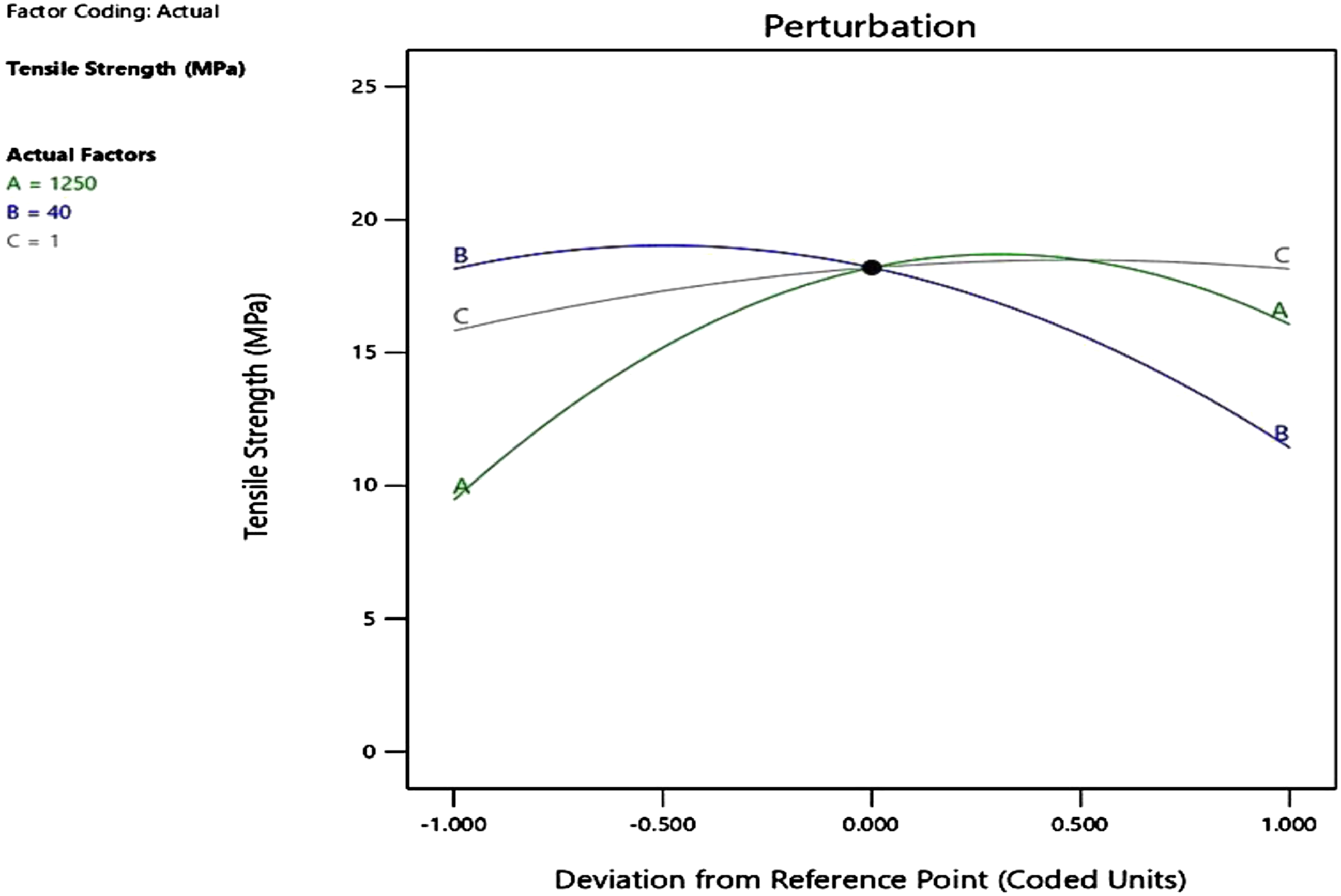
Process parameter optimisation using desirability function approach
Desirability is a function that varies from zero outside the bounds to one at the goal. The numerical optimization identifies the maximum value of the desirability function. By altering a goal’s weight or significance, its characteristics may be modified. All objectives are incorporated into one desirability function for various responses and factors. The objective of optimization can be utilised to maximise, minimize, or achieve the desired response value. Design expert software’s inbuilt desirability function approach was utilized to determine the optimal process parameters for achieving maximum tensile strength.
The optimization criteria in this work.
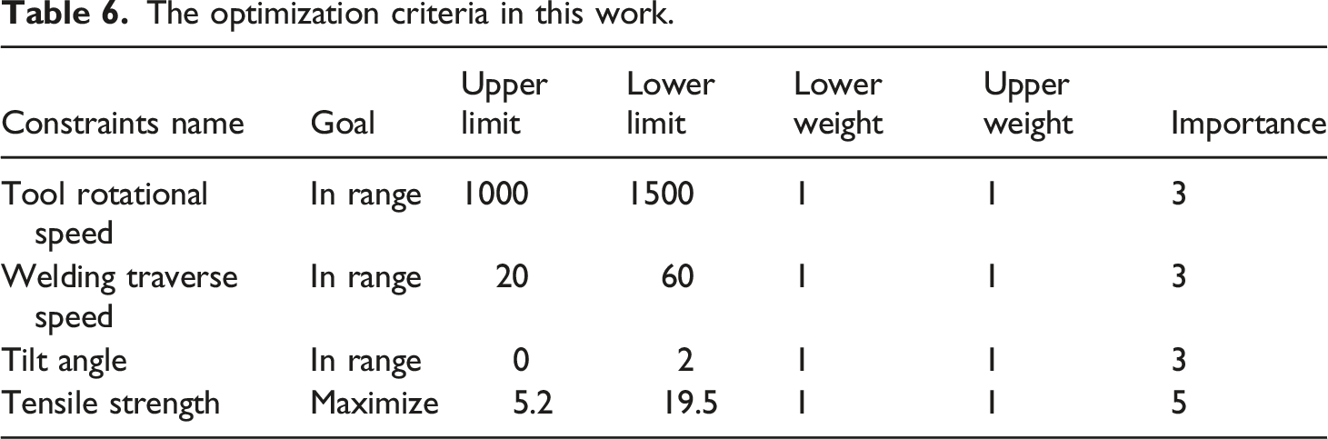
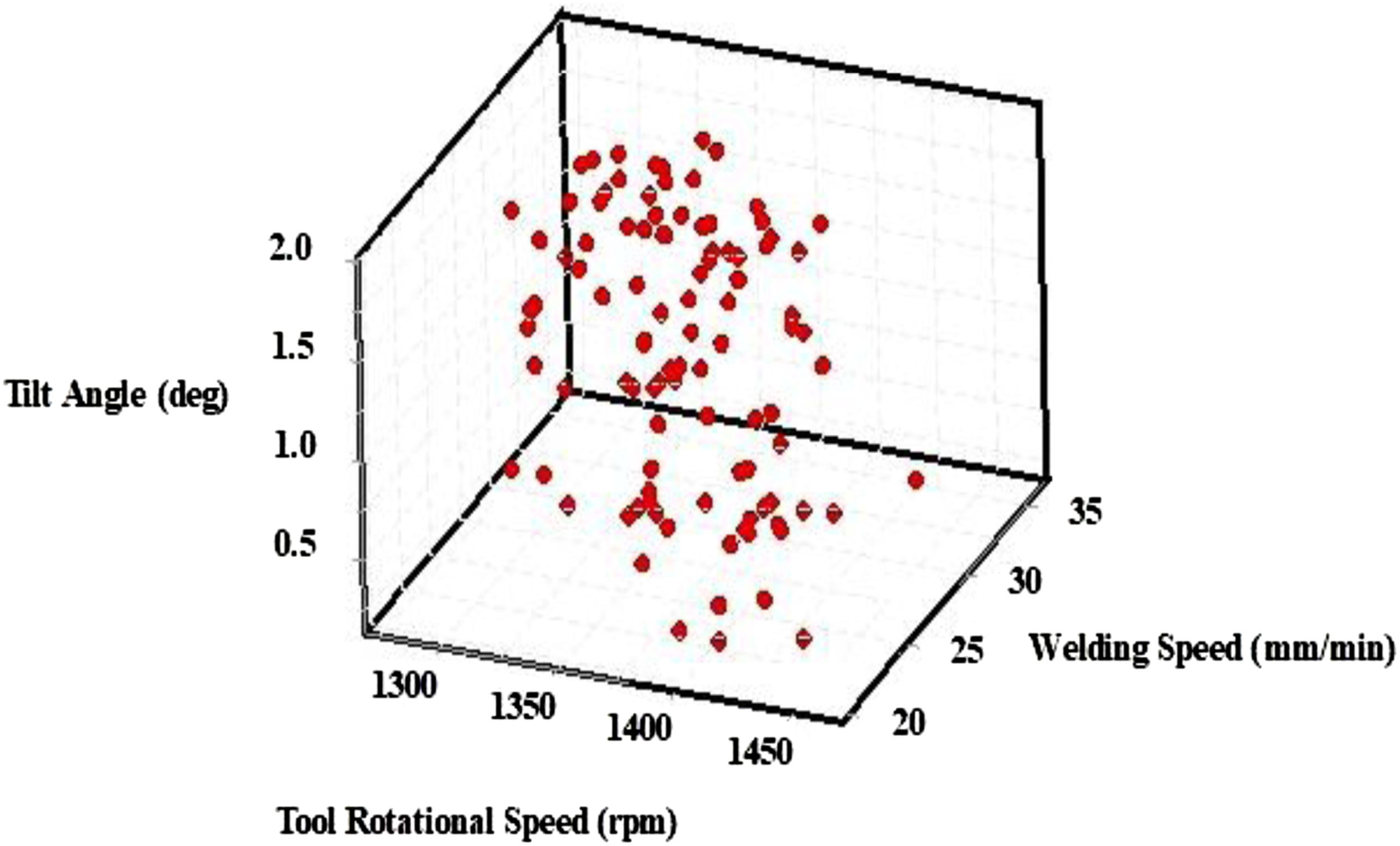
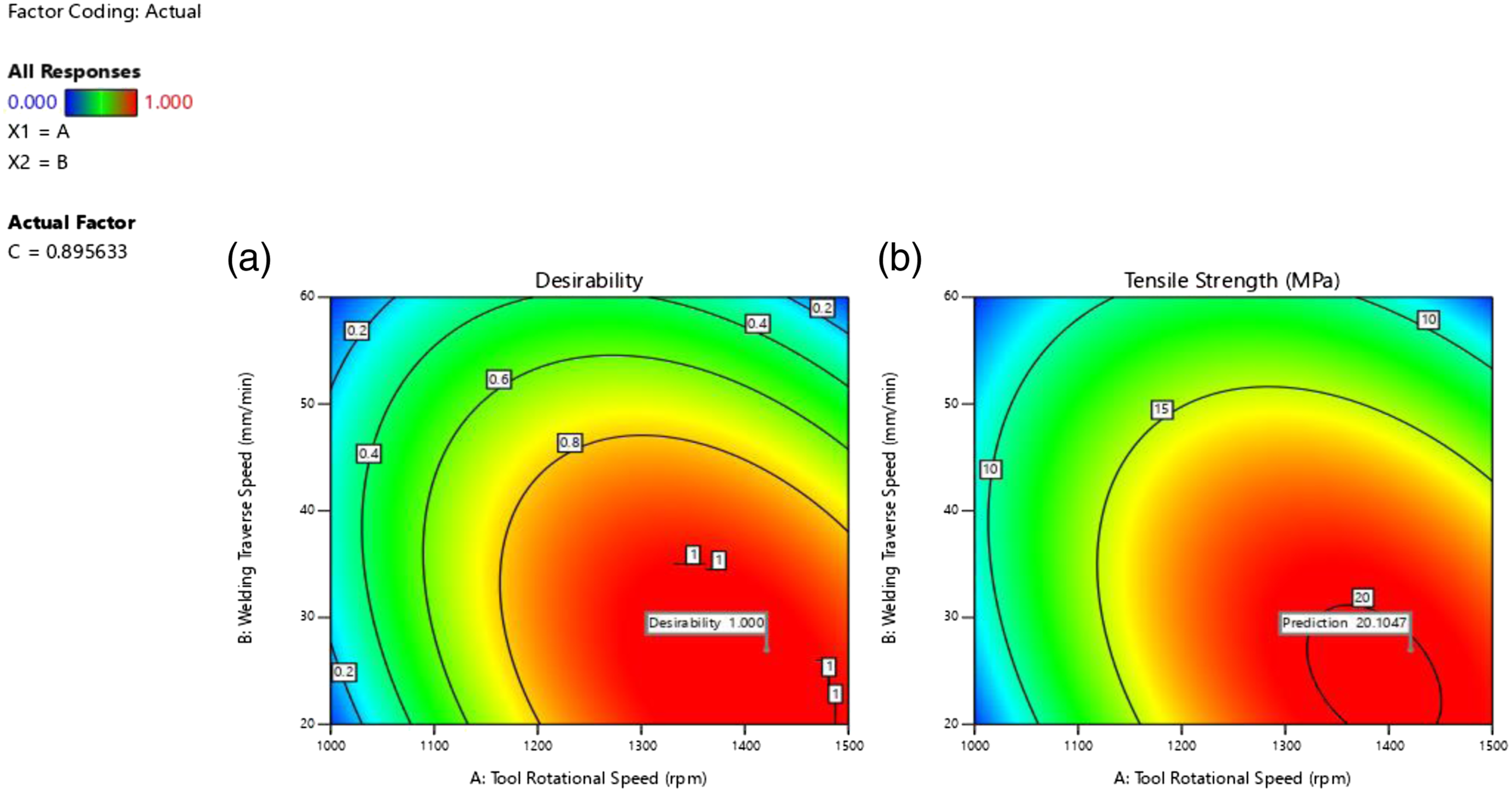
Figure 7 shows the optimal solution for which maximum desirability is achieved to get maximum tensile strength. The one with maximum desirability is selected from Figure 8, which shows the optimal solutions obtained using the desirability approach using RSM. A set of 100 desirable values for getting optimal tensile strength is represented. From the data set, one with maximum desirability is taken for performing the confirmation test, which is depicted in Figure 7. The significance of tool rotational speed and weld traverse speed on tensile strength is shown in Figure 9. Plot 9(a) is the contour plot for maximum desirability, whereas 9 (b) shows the contour distribution for maximum tensile shear strength. This plot clearly shows maximum parameter ranges for achieving high tensile shear strength, tool rotational speed to 1330–1490 r/min, and weld traverse speed from 23–34 mm/min. Maximum tensile strength of 20.1047 is obtained at a desirability of 1. Optimal solutions for maximum desirability. Optimal solutions based on desirability approach using RSM. Contour plot for (a) Desirability and (b) Tensile strength.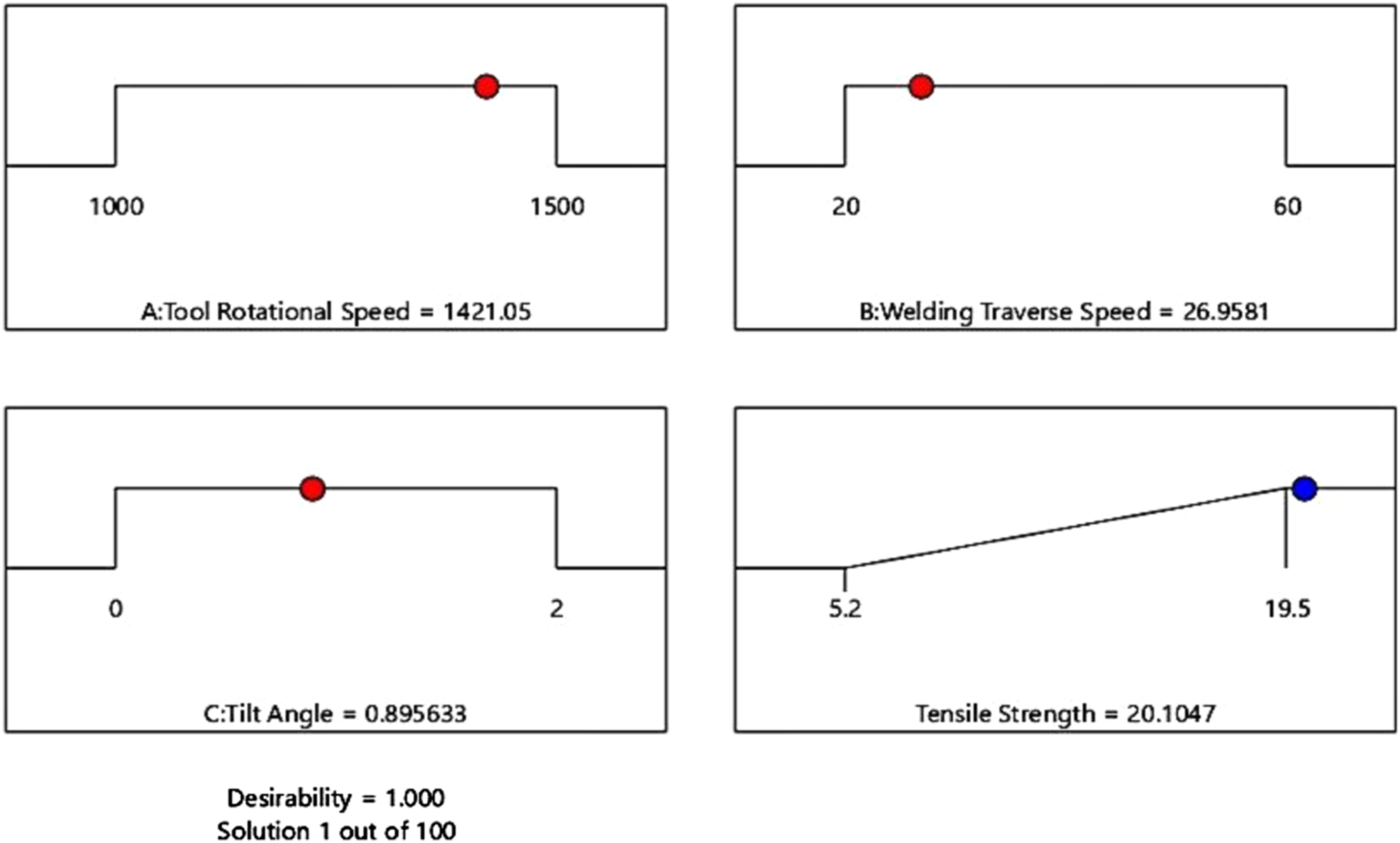
Artificial neural network validation of results
Artificial neural networking was utilised to estimate the tensile shear strength values for the optimal setting proposed by RSM. In the present investigation, tool rotational speed, weld traverse speed, and tilt angle are the ANN inputs, with tensile strength as the output. Table 4 illustrates the outcomes of experimental tests. For ANN modelling, a feed-forward backpropagation approach with input, hidden, and output layers of neurons was chosen. In the input layer, there are three nodes for input welding parameters, one node for the response parameter, and 10 nodes in a single hidden layer. Consequently, a 3-10-1 ANN framework has been developed. The data set is split into 70:15:15 proportions for ANN model training, testing, and validation. The developed ANN architecture is shown in Figure 10. The ANN model used in this analysis was made with the help of MATLAB’s neural network toolbox. ANN Architecture for Tensile strength.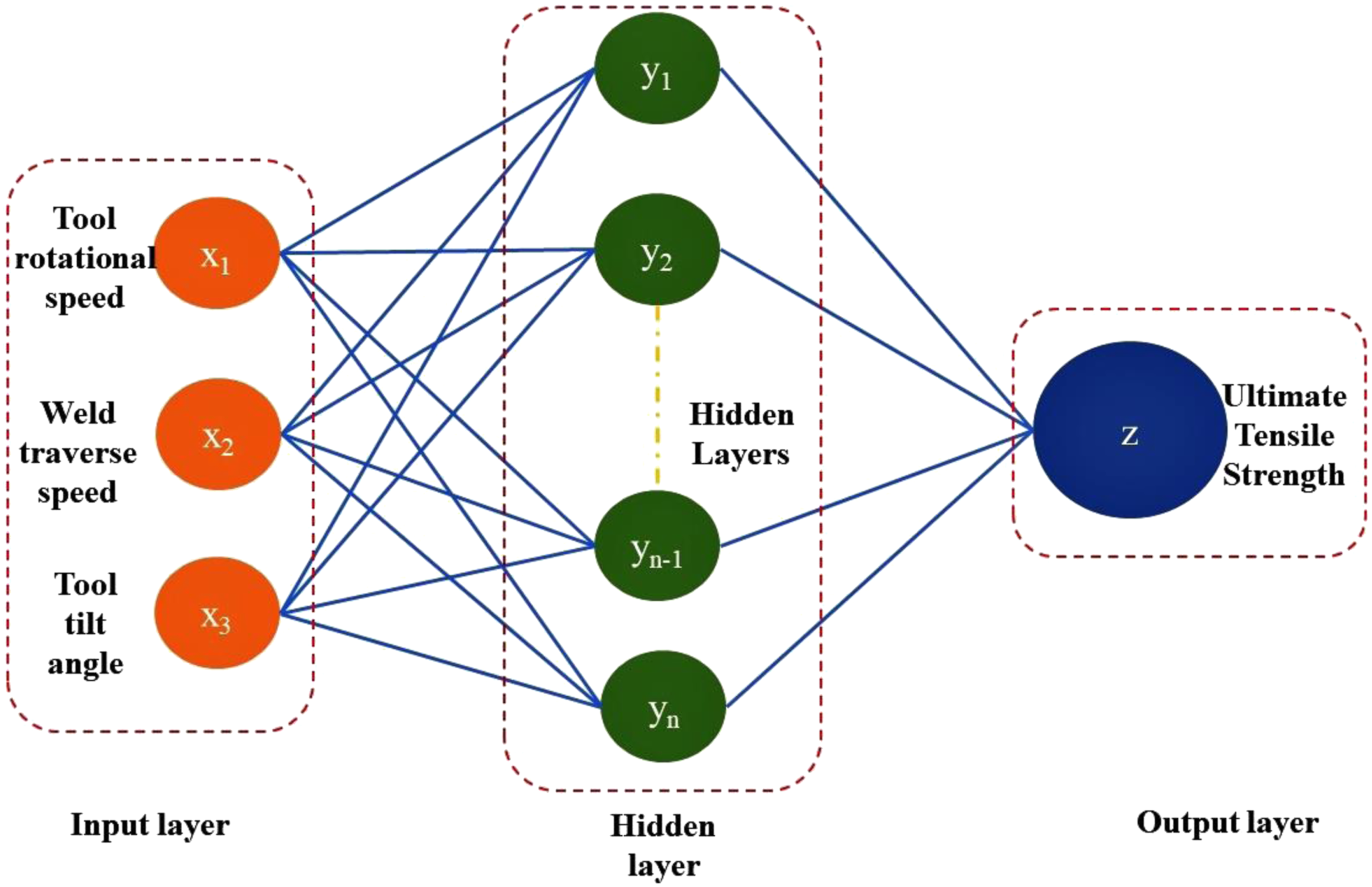
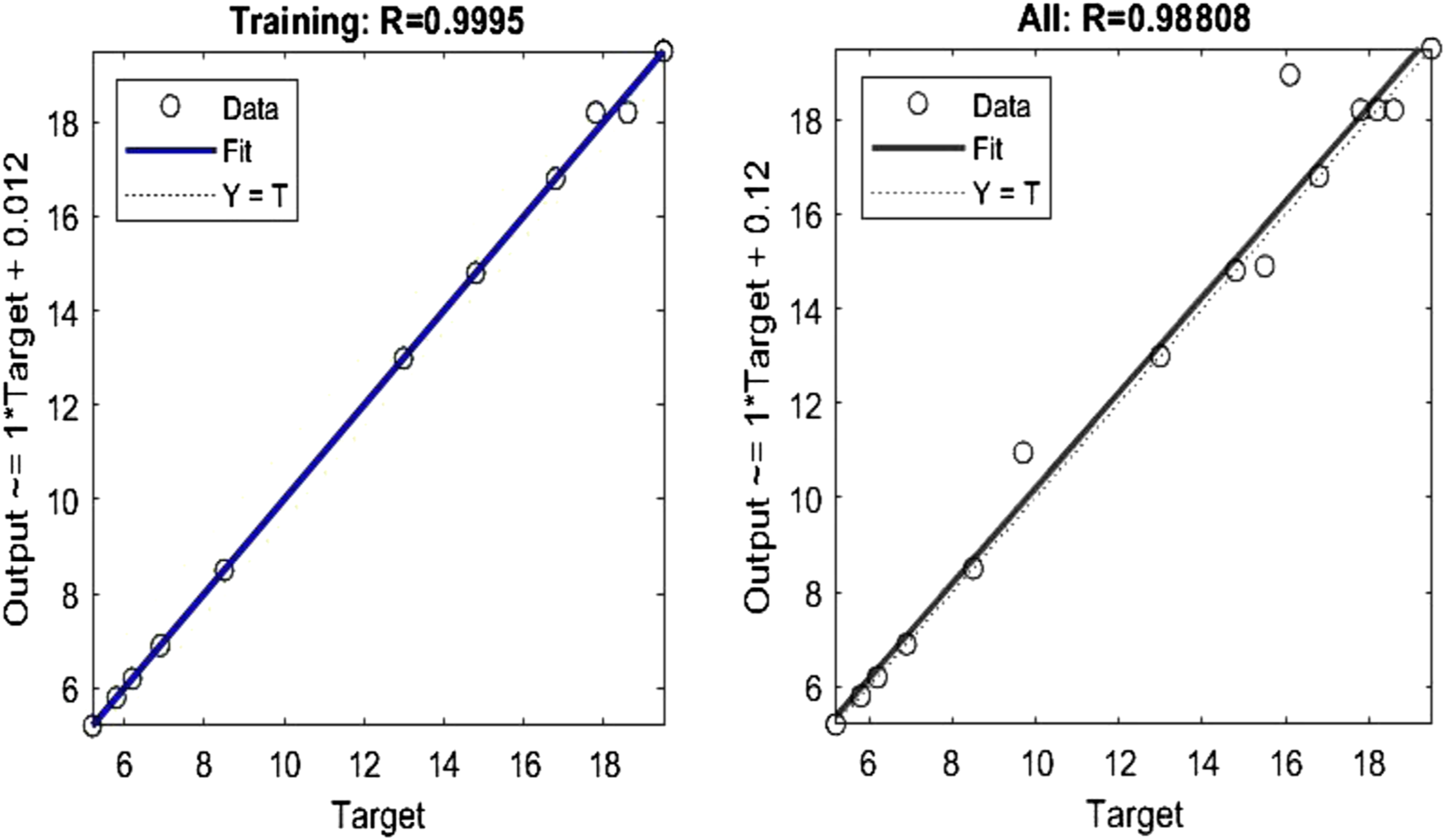
A verification test of three randomly selected welding conditions was performed to validate the response surface equation produced from regression analysis. The equation was used to calculate the experimental range. The verification test indicates that the percentage difference between the expected and predicted values is minimal, which results in an accurate model. The performance of the ANN is validated in terms of mean square error values. The deviation of the ANN outcomes from the desired results is the error. Figure 11 shows the effect of the mean square error on training, testing, and validation versus Epochs. The agreement of training and test data is validated by the gradual decrement of mean square error values after each epoch. The decrease in mean square errors happens because the weights get updated after each epoch. The error between the actual and predicted values is minimal, indicating that the developed model is adequate and the actual value is comparable to the expected value. Another criterion for measuring the accuracy of predicted values is the correlation coefficient. The correlation coefficient, which takes on values between −1 and 1, quantifies the linear correlation between two sets of data. Figure 12 depicts the linear correlation between the target and predicted values for training and test data. The training and testing errors are low, indicating that the suggested ANN model performs effectively. In the meantime, the regression coefficient for the current study was 0.988 for the test data set, indicating that the developed model is appropriate for predicting tensile shear strength. Variation of MSE of training, testing, and validation v/s Epochs. Linear correlation between the target and predicted results for the training and test data.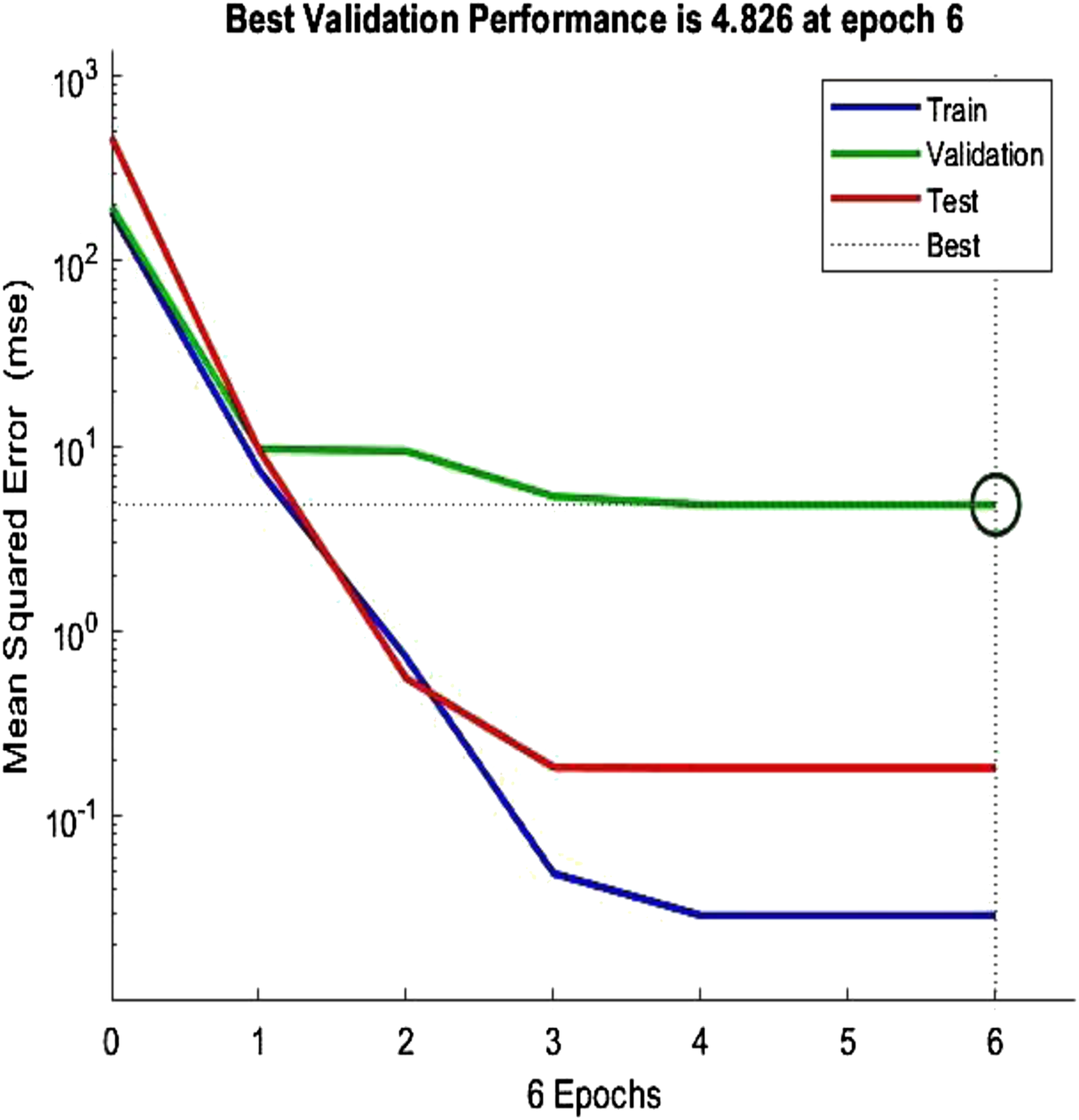
Validation of RSM and ANN predicted value at optimal weld condition
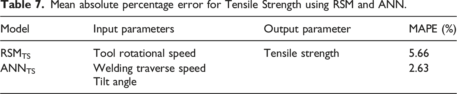
Mean absolute percentage error for Tensile Strength using RSM and ANN.
Confirmation test and validation using ANN Model.
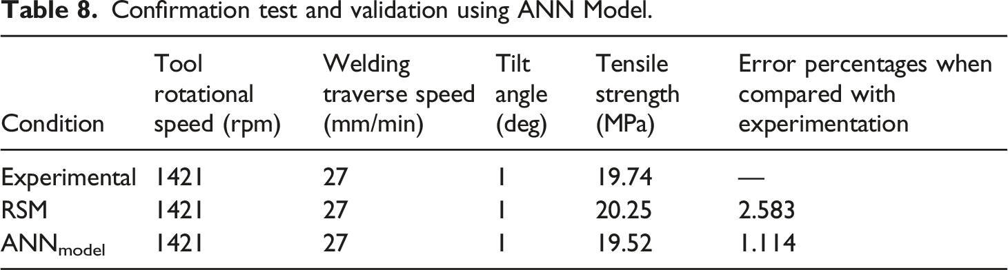
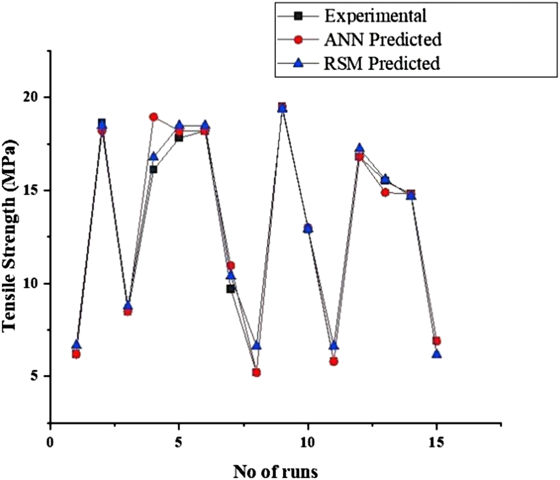
Comparison between Experimental versus RSM vs. ANN values of Tensile strength.
Characterisation of hybrid welded joint
Tensile characterisation
At a rotating speed of 1421 r/min, a welding speed of 27 mm/min, and a tilt angle of 1°, the maximum tensile strength of 19.74 MPa is obtained. Tensile strength values increase with rotational tool speed but decrease with higher welding speeds. The tensile strength increases initially with tilt angle but decreases at higher tilt angle values. A bigger aluminium anchor with a large adhesive-bonded area is formed at higher rotational speeds at the joint interface due to the resolidified polymer. The shearing action at higher speeds produces more metallic fragments in the stir zone, which reinforces the weld and enhances the load-bearing capability of the joint.
The heat input also plays a vital role in the tensile strength of the welded joints. Tool rotational and traverse speeds have a significant impact on the specific weld input energy during FSW. Increasing the rotational speed of the tool generally enhances frictional heating and mechanical stirring. Higher welding temperature improves weld quality by enhancing the plastic softening and fluidity of the weld material. 22 The process parameters are optimised in such a way that the heat developed should not exceed the degradation temperature of the polymer. In such cases, the heat developed can cause the polymer to degrade and subsequently causes a reduction in joint strength. This undesirable excessive heat developed on the polymer at high temperatures enhances the interactions between dislocations, and other crystalline imperfections, increasing the dislocation motion as reported by Moshwan et al. 18 (2015). This can be the reason for the detrimental effect on tensile strength at higher undesirable heat values. However, in our current study, the heat developed was below the degradation temperature of the polymer, so more Aluminium 5754 transportation in P.A. than dislocation was observed, reinforcing the joint, resulting in mechanical interlocking between these two materials and, as a result, increased strength of the welded joint.
Microstructural characterisation
Figure 14 depicts the optical micrographs of the weld cross-section. A smoother weld surface with less distortion is produced under optimal conditions, as shown in Figure 14(a). Figure 14(b) shows the macro image of the weld section having no voids and gaps at the macro level. This is due to optimal frictional heat developed at optimal conditions has a pseudo heat index value (ω2/r) of 74,786.7 and peak temperature value of 246.6 C at a rotational tool speed of 1421 r/min, weld speed of 27 mm/min, and tool tilt angle of 1, which benefits proper mixing of materials causes smooth surface finish. The Al anchor on the retreating side is smaller in size than that formed on the advancing side because of the higher peak temperature values of the advancing side than on the retreating side. Figure 14(c)–(f) represents the advancing side, retreating side, stir zone, and weld interface, respectively. The macrostructure reveals that the stir zone consists of relatively large aluminium fragments mixed inside melted and resolidified polyamide matrix, as seen in Figure 14(e). The stir zone is found to be a combination of aluminium fragments of different sizes entrapped in the melted and resolidified polyamide. The difference in the size of aluminium fragments is due to the non-uniform temperature distribution and flow of materials from the retreating side to the advancing side. Optical Microscopic image of the different region of the welded joint.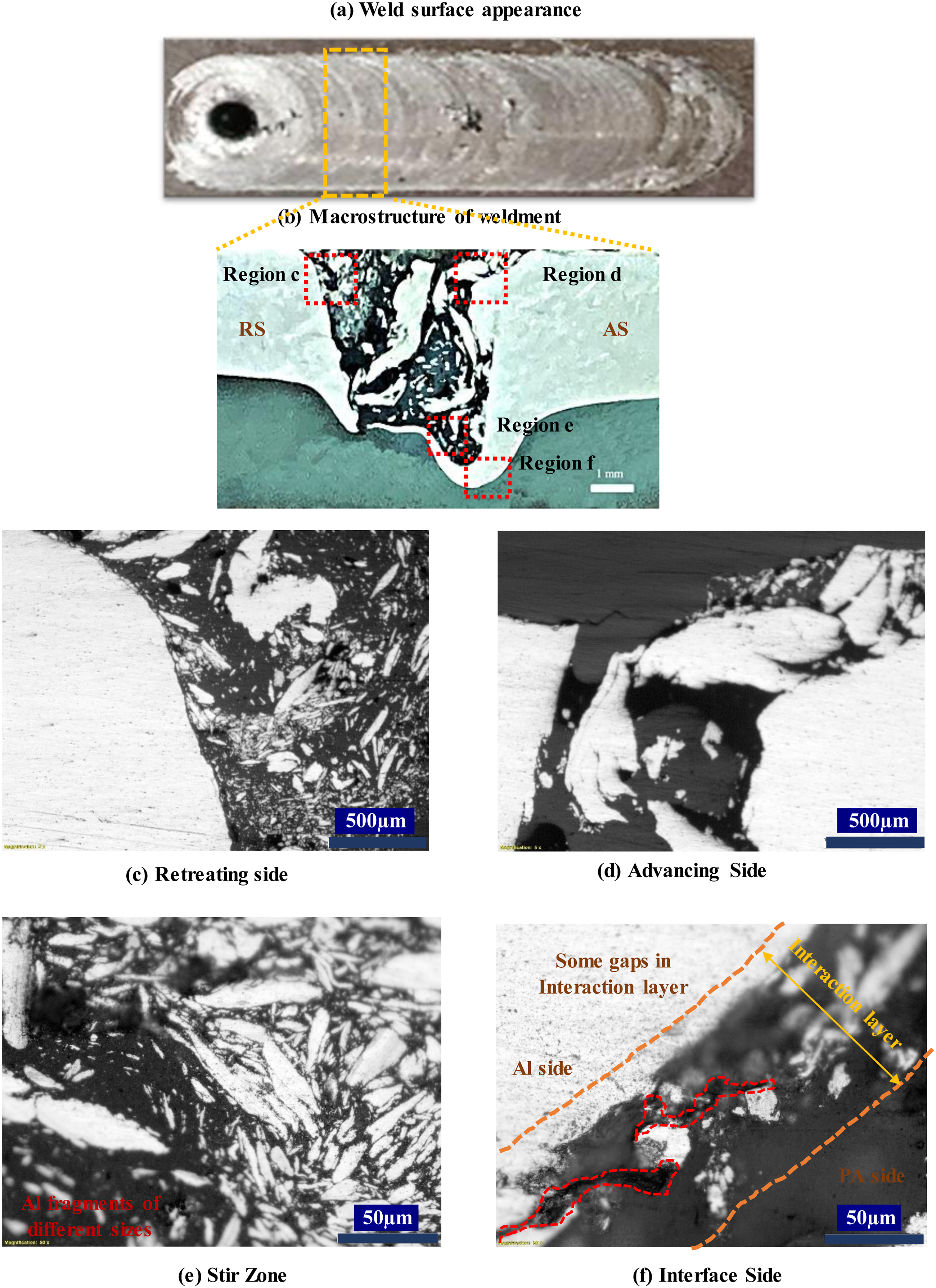
The weld traverse speed considerably impacts the size and shape of the aluminium fragment; higher speeds tend to produce coarser fragments. 37 The larger fragments present in the lower retreating side inhibit appropriate material flow in and around the region, leading to the formation of voids. The intermixing between finer aluminium fragments and polymer reinforces the weldment resulting in superior mechanical interlocking, hence better joint strength. 38
The region near the interaction layer where only thermoplastic material is present without aluminium fragment which enhances the interfacial property, thereby increasing the joint strength.7 A small gap observed at the metal-polymer interface is shown in Figure 14(f), which happens due to thermal stresses developed during the cooling phase due to the differences in the thermal expansion coefficients between the metal and polymer.
The heat developed due to friction between the rotating tool and workpiece causes material softening, resulting in the movement of materials from the retreating side to the advancing side. Therefore, rigorous stirring action at higher rotational speeds results in aluminium to polyamide interlocking. The interfacial SEM image shown in Figure 15 shows the aluminium 5754 with bright white, grey layers and polyamide melted and resolidified matrix with dark grey contrast. The higher frictional heat developed during welding melts the polymer, which resolidifies over the metal surface during the cooling stage.2,24 This indicates the presence of adhesive joining between aluminium and polyamide. SEM image of the AA 5754-PA resolidified region in the weld interface.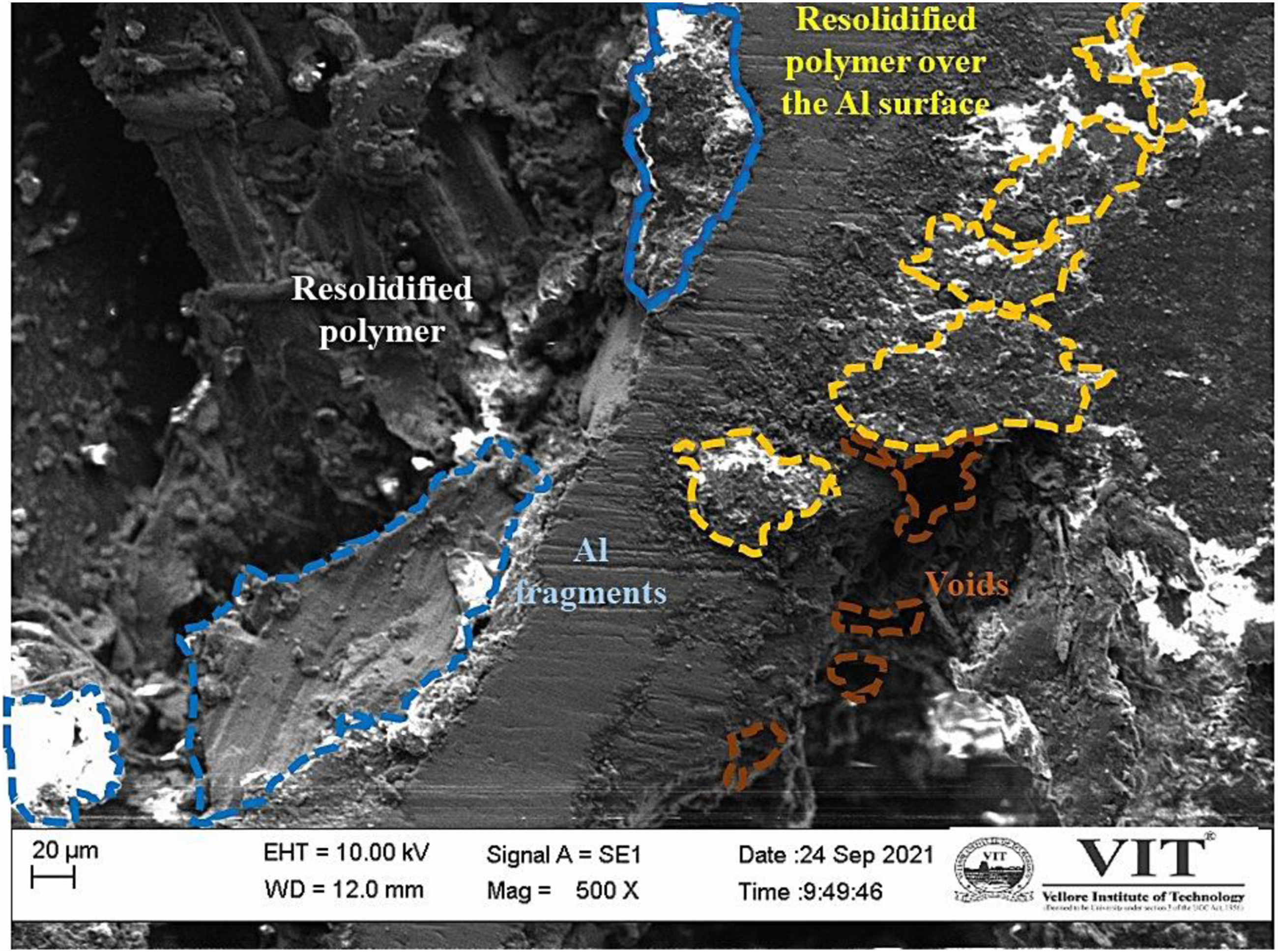
The mechanical interlocking effect of the zigzag aluminium pieces and the melted and re-solidified polyamide matrix, as well as the chemical bonding at the aluminium 5754-PA interfaces caused by the adhesion between the aluminium oxide and polymer, is identified as the bonding mechanism. The mechanism of molecular bonding between aluminium and polyamide during FSW is adhesion due to the Al-O-C bond. This bond formation is due to the combination of the carbonyl group of polyamide and aluminium oxide layer present on the aluminium surface. They combine to form a C-O-Al bond. During thermomechanical action, this bond breaks into C-O and Al-O, and later they recombine to form C-O-Al of a longer chain. It should also be noted that PA polymer chains do not contain any function- Al groups, so it is likely that any bonding between the polymer and surface aluminium oxide is mainly secondary, or Vander Waal’s bonding is the mechanism. 19 Thus, the joining of aluminium 5754 and polyamide is a combination of micro and mechanical interlocks and with chemical adhesion.
Figure 16 shows the SEM/EDS images at the interaction layer of the weld zone. The SEM contrast characteristics cannot be used to prove the chemical bond between aluminium and polymer, so element mapping is necessary. The element identification in these areas is shown by the EDS spectra of the weld interface. The interaction layer containing aluminium, magnesium, and carbon was detected using a highly magnified image. More oxygen in the interaction implies more polymer degradation because liquid and solid-state processes produce additional aluminium oxide. This layer might potentially serve as a supplementary bonding mechanism between the metal and the resolidified polymer. It is concluded that the interaction layer’s adherence to the polymer and aluminium has a substantial impact on joint strength. Besides micro and macro interlocking, it is regarded as a bonding owing to chemical adhesion. SEM/EDS image of the interaction region of the welded joints.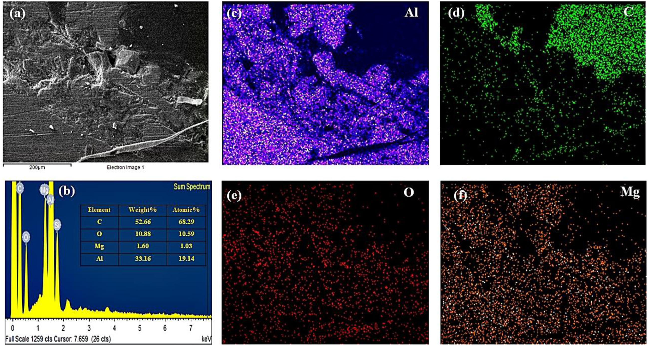
In the weld nugget, small gaps are observed between the interaction layer and the polymer matrix, as well as polymer and aluminium matrices. The thermal stresses created by the considerable differences in the coefficient of thermal expansion (CTE) of polymer and aluminium caused this gap to develop during the cooling phase of the joint. These gaps act as fracture initiation points while the application of shear loads. These gaps should be minimum to achieve better joint strength.
Micro hardness studies
Microhardness readings were taken in an area inside and outside the stir zone to study the effect of welding on hardness values and the average hardness values of each area were measured. The average hardness of the polyamide inside the area of the stir zone was found to be decreased after welding. The hardness of the polyamide before welding was 79 (Shore D), and after welding, it was found to be 71(Shore D). This happened due to molecular weight loss due to frictional heat developed during welding at lower welding speeds. 39 The microhardness of the aluminium 5754 fragments in the stir zone improved from 63HB to 69 HB than the HAZ due to graining effect due to the frictional heat. This graining effect is due to higher strain rates subject to metal fragments in the stir zone while shearing. The reason for this variation in hardness on the metal side is due to the thermo-mechanical effect of the tool stirring action, increased the hardness of this area by slight reduction of grain size according to Hall–Petch effect. 5 At higher tool rotational speed and lower weld speed, the heat input increases, which improves the hardness of the aluminium side, whereas it decreases the hardness of the polymer side.
Thermal history
While performing the confirmation test, the temperature was constantly monitored along the weld zone rather than at a particular point. The temperature versus welding time plot is shown in Figure 17. The IR camera is focused on the complete area of the weld zone (tool-workpiece contact region) continuously throughout the welding cycle. The objective was to determine the peak temperature value attained during the welding under optimal conditions. The peak temperature while welding should not cross the decomposition temperature of the polymer. Therefore, the inference from the study is that the peak temperature observed, which is 246.4 C, which is well below the decomposition temperature of the polymer, which is optimal for getting better joint strength. After the welding cycle, the temperature dropped gradually. The temperature results from the higher stirring action of the FSW tool, which generates heat on the aluminium side, causing frictional heat to build in the stir zone.
40
Thermal history of the joint welded at optimal condition.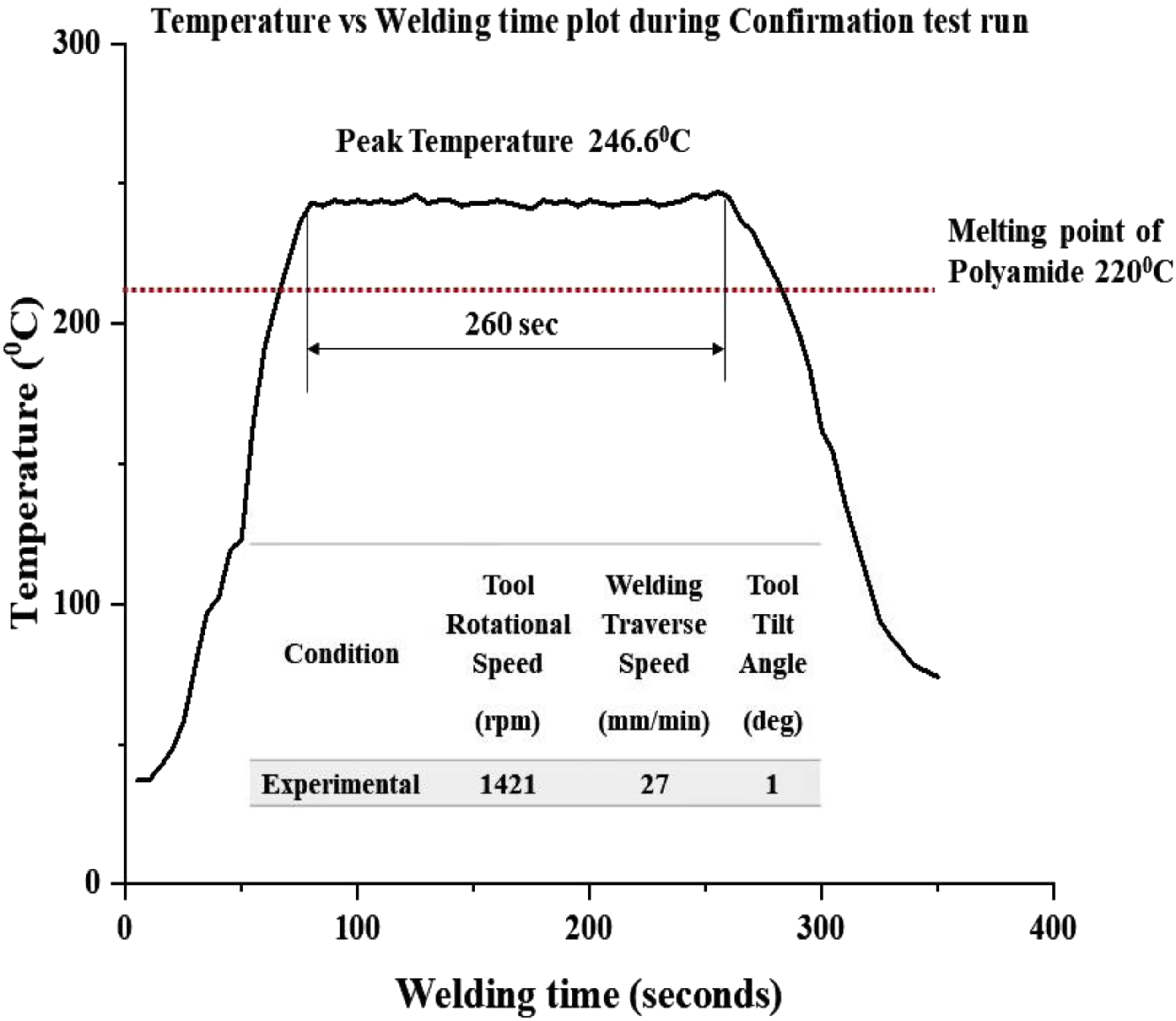
Conclusions
This study investigates the influence of friction stir welding parameters on the joint strength of aluminium 5754 and polyamide. Statistical approach-based response surface methodology (RSM) and soft computing-based artificial neural network (ANN) are used to develop predictive models, and their model effectiveness is compared. The following are some of the most important findings of this investigation. • The maximum tensile strength of 19.74 MPa is reached at a rotational speed of 1421 rpm, a welding speed of 27 mm/min, and an angle of 1°. Tensile strength values increase as tool rotating speed increases but decrease as welding speeds increases. • Micro/Macro mechanical interlocking with chemical adhesion is the mechanism behind the joining of aluminium 5754 with polyamide. At higher rotational speed and lower welding speeds, the heat input increases, which improves the hardness of the aluminium side, whereas it decreases the hardness of the polymer side. The peak temperature of 246.6 C is developed while performing an optimal experimental run which is above the melting point and well below the degradation temperature of the polyamide. • The ANOVA results of RSM suggested that welding speed and tool rotational speed were the most influencing factors. At the same time, tilt angle was the least significant factor for FSW of the Al-polymer hybrid structure. • The combination of weld traverse speed and rotational speed significantly affected tensile lap-shear strength. Welding speed from 20.037 to 34.667 mm/min and tool rotational speed from 1274.528 to 1470.79 rpm at tilt angle under 2° were identified as optimising the desired joint strength using FSW of aluminium 5754 to polyamide hybrid structures. • RSM and ANN were found to be excellent for optimisation and validation techniques. The performance of ANN models to forecast tensile strength within input welding parameter ranges is superior to that of the regression model using RSM. So, predicting joint strength enhances the productivity of the manufacturing process, thereby better joint efficiency.
Footnotes
Declaration of conflicting interests
The author(s) declared no potential conflicts of interest with respect to the research, authorship, and/or publication of this article.
Funding
The author(s) disclosed receipt of the following financial support for the research, authorship, and/or publication of this article: This work was supported by the Vellore Institute of Technology (VIT), Vellore (seed grant).