
Abstract
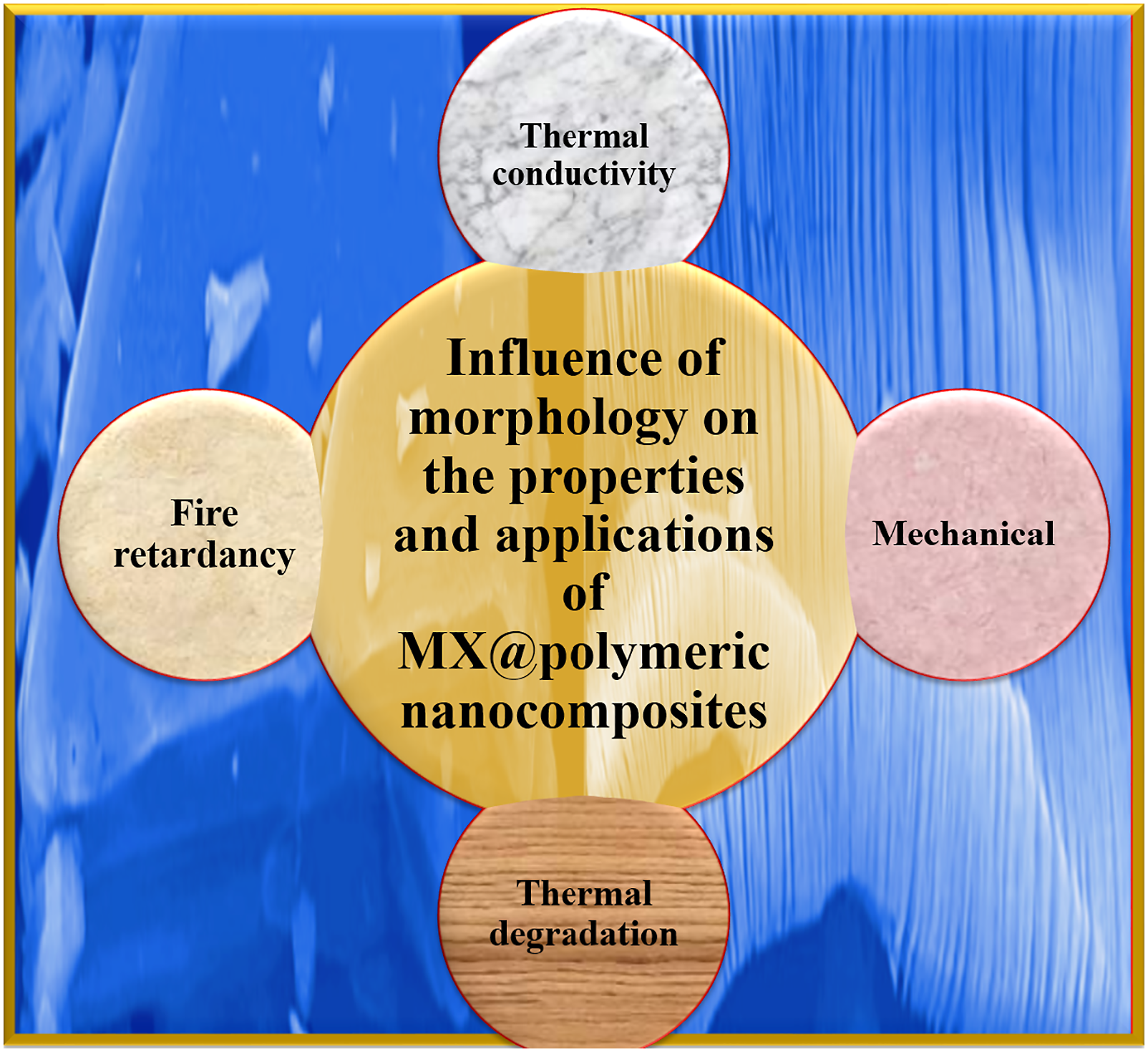
Morphological characterization of fabricated MXene (M-X) Polymeric nanocomposites (M-X@PNC) is critically imperative for in depth appraisal of surface-topographical and compositional evaluation of M-X@PNC. The garnered properties of M-X@PNC are function of the degree of nanoparticulate distribution and embedment within the polymeric matrices and their overall effectiveness at improving the nanocomposites properties, vis-a-viz mechanical, heat dissipation as well as heat deflection properties along with potential applications. Inherently interacting functional entities within M-X@PNC architecture are basis for garnered properties including flammability, chemical, thermal, electrical conductivity and so on, which directly affect potential applications. Thus, this paper elucidates the influence of morphology and architecture on M-X@polymeric nanoarchitectures properties and applications.
Keywords
Introduction
Nowadays, the evolution of 2-D-layered “MXenes”, have greatly aroused the interests of researchers and industrialist across the globe attributed to their outstanding electronic and architectural disposition which enhance their utilization for multifunctional applications. 1 M-X refers to a set of transitionally inclined metallic carbides, carbonitrides or nitrides garnered from the chemically inclined delamination of 3-D ternary (or quaternary) entities known as MAX phases. 2 From the emergence of graphene (GN), 3 a significant number of evaluations have been conducted on existing 2-D nanomaterials (NM), ascribed to their outstanding mechanical, optical as well as electronic properties. 4 After GN, transitional metallic phosphorene, dicalcogenides, as well as their derivatives are instances of elevatedly studied 2-D NM.5,6
However, M-X are additionally derivable from other nano-sheet material such as Mo2Ga2C 7 and Zr3Al3C5. 8 Moreover, M-X denote the general formula Mn+1XnTx (n = 1–3), where M depict the transitionally affiliated metallic substrates (Sc, Ti, Zr, Nb, etc.), and X represent carbon and/or nitrogen as Tx portends the hydroxyl, oxygen or fluorine terminals attained via synthesization.9–11 Embedment of interlayer spacial structures within M-X nano-sheets is pathway to restraining the restackage of Ti3C2Tx sheets while inhibiting this trend.
M-X is fabricated via selectively etching the MAX phase. Post etching, M-X formula is denoted as Mn+1XnT2, as T2 depicts functionalization of the surface entities emanating from the etching procedure and terminals which emanate from the synergy of oxygen (O), hydroxyl (OH), and F entities, as well as exchangeable cations and protons, as the inter-sheet spacing is refilled with water. 12 Meanwhile, the exfoliated 2-D M-X Ti3C2Tx exhibit peculiar 2-D sheets with its morphology appearing like that of GN interlayers. 12
Ti3AlC2 microarchitecture reveal a metallic polycrystalline sheet architecture with elevated aspect ratio. Generally, MAX phase display a hexagonally crystalline architecture with P63/mmc, wherein M–X forms octahedrally architecture sand-winched between A sheets/layers. Ti3AlC2 bulk cross-section display a smooth surface as well as layers in arrangement like a crystalline rock. Figure 1 presents various magnifications of M-X SEM images.
13
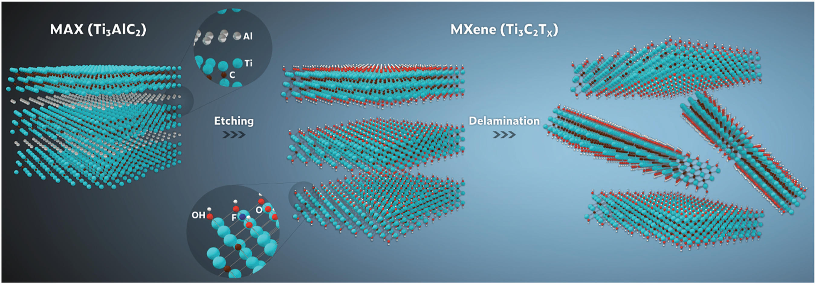
Figure 2 is schematic representation of the general synthesization route of Ti3C2Tx.
14
Varying magnifications of M-X SEM images. Schematic representation of the general synthesization route of Ti3C2Tx.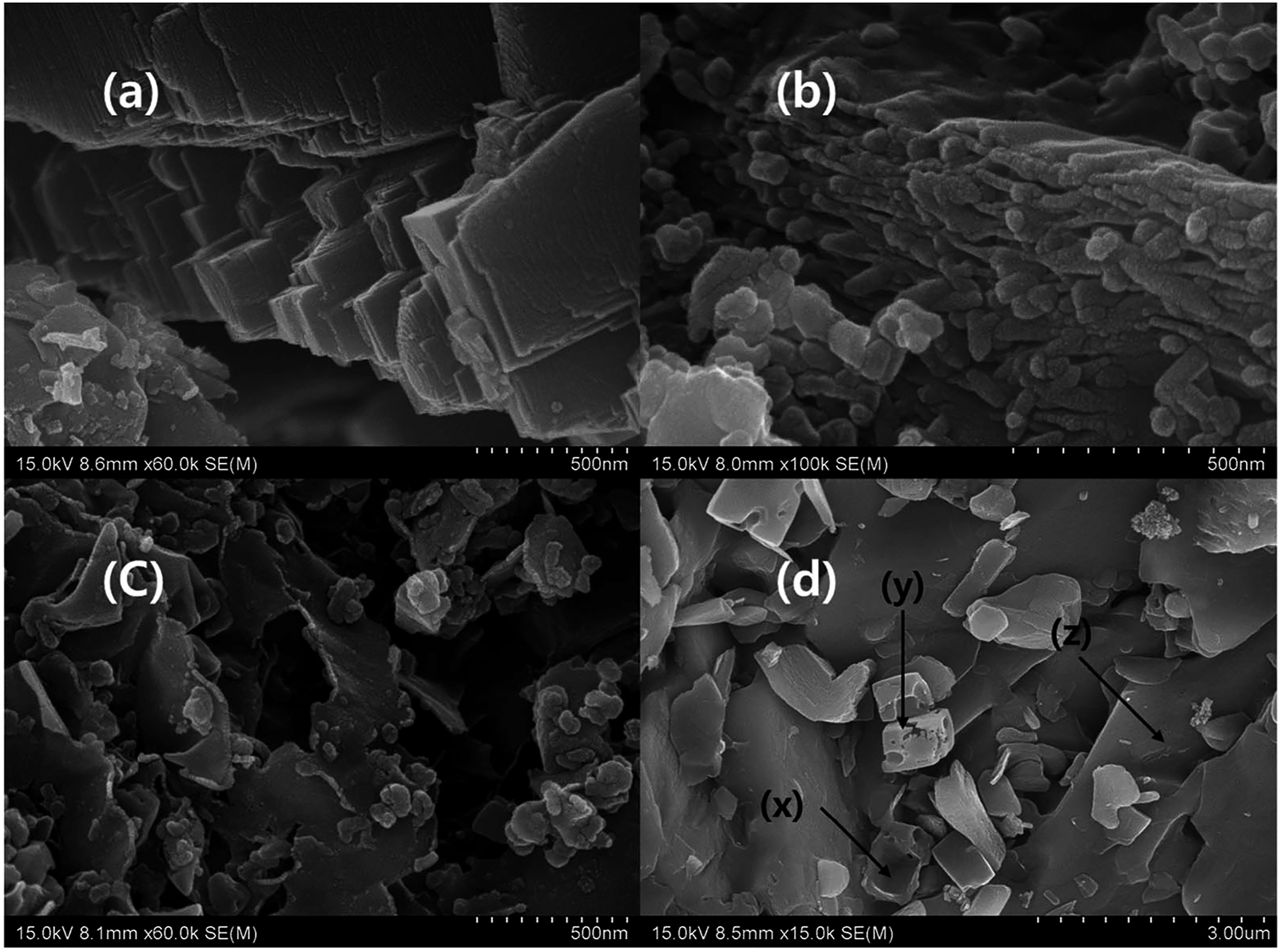
Therefore, in this paper, the interaction and synergistic mechanism between M-X and polymeric architectures are investigated via morphological appraisal while their effect on garnered properties and uses are confirmed utilizing Field emission scanning electron microscopy (FESEM), high resolution transmission electron microscopy (HRTEM), Transition electron microscopy (TEM), Atomic force microscopy (AFM), Scanning electron microscopic (SEM) apparatuses, and so on. Furthermore, the surfacial chemistry and interfacial functional entities interacting within M-X@PNC are appraised and confirmed from Fourier transform infrared spectroscopy (FT-IR), Raman spectroscopy (RMS), X-ray diffraction (XRD), X-ray photoelectron spectroscopic equipments (XPS) and so on.
Morphology and architecture are two very vital determinants of the properties of polymeric nanocomposites generally. In the case of M-X@polymeric nanocomposites there is paucity of information in this regard. Hence, this paper offers first hand insight into the effect of M-X@PNC morphological arrangement and architectural/structural characterization on achieved properties and prospective uses of the materials, which is the novelty of the present elucidation. Finally, challenges and future prospects of M-X@PNC are elucidated.
Emerging trends in M-X@PNC morphology
In order to achieve optimization of the properties of M-X@PNC, layered/sheet-like materials exfoliation and complete homogeneous distribution of these exfoliated sheets across the entire polymeric matrix are critically imperative. Nevertheless, it is essential to depict that mechanically affiliated reinforcements may not essentially undergo optimization with single sheets. Hence, multiple sheet M-X may proffer beneficial for use in polymeric nanocomposites as M-X exfoliation can undergo minimization to optimized state. Thus, in order to attain simultaneous exfoliation and effective distribution within the morphology, the strategy by which M-X@PNC are fabricated fundamentally influences their morphological architecture as well as garnered properties. Three major strategies of M-X@PNC processing are prevalent including melt processing, in situ polymerization, as well as solvent blending/casting/filtration. Though synergies of these procedures in fabrication procedures are feasible.
Solvent procedure involves M-X incorporation within polymeric matrices utilizing a solvent. This strategy is mostly the commonest M-X@PNC fabrication strategy because it is proficient at the laboratory level with direct usage of colloidal MX.1–3,15 For melt fabrication route, M-X is embedded within polymeric matrices conducted above melting point (MP) of the polymer. Melt processability involves strategies including extrusion, hot pressing, as well as injection molding capable of being utilized in alignment impartation to M-X nanosheets. These strategies are specifically essential for large-scale fabrication of M-X NCs with feasibility of refinement or optimization. 16 In situ polymerization is strategy involving monomeric polymerization in the presence of a reinforcement. Here, the polymeric chain network is formed proximally close to the nanofiller surfaces whilst the monomeric intercalation, subsequented by polymerization is capable of resulting in layered expansion as well as exfoliation.
Morphological and structural trends of Ti3C2Tx M-X@PVA nanocomposites
M-X, a novel set of 2-D nanomaterials, have recently garnered escalating attention due to their exceptional properties for a versatile range of prospective applications. Thus, in a study Ti3C2Tx M-X@PVA nanocomposites were fabricated and investigated for morphology as it affects heat dissipation properties for usage in related gadgets using temperature-based Raman spectroscopy as well as polarized-laser power-based Raman spectroscopy. Results revealed enhanced heat dissipation properties of M-X@PNC from −0.06,271 to −0.03,357 cm−1/K ascribed to elevated Ti−O bonding created between M-X@PVA as affirmed by X-ray photoelectron spectroscopic appraisal.
17
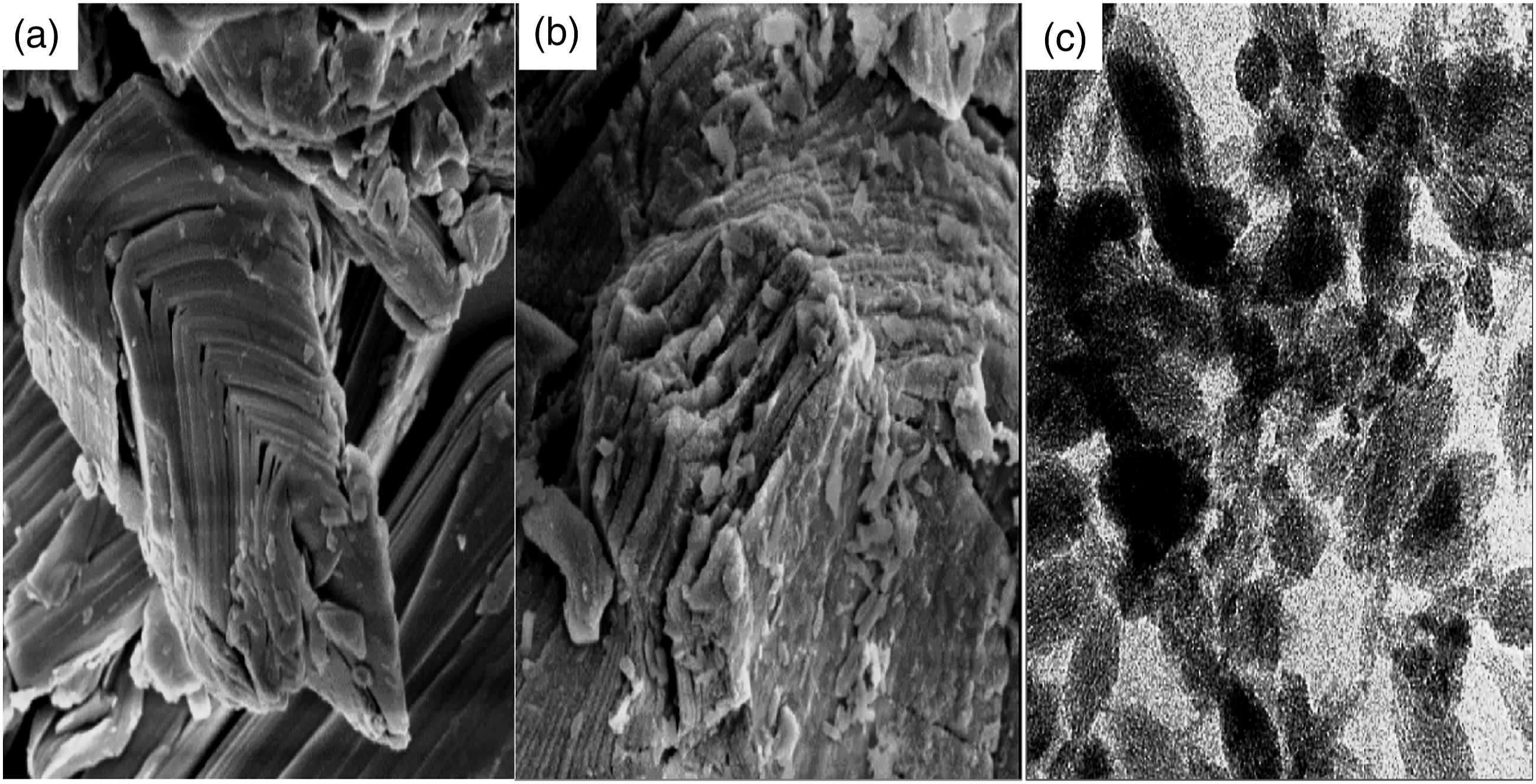
Figure 3 is a SEM image garnered from the morphology of M-X@PNC. Herein, Ti3C2Tx displayed a layered/sheet morphology appearing like exfoliated graphite, as shown in SEM images in Figure 3(a).
17
SEM image of M-X@PNC morphology.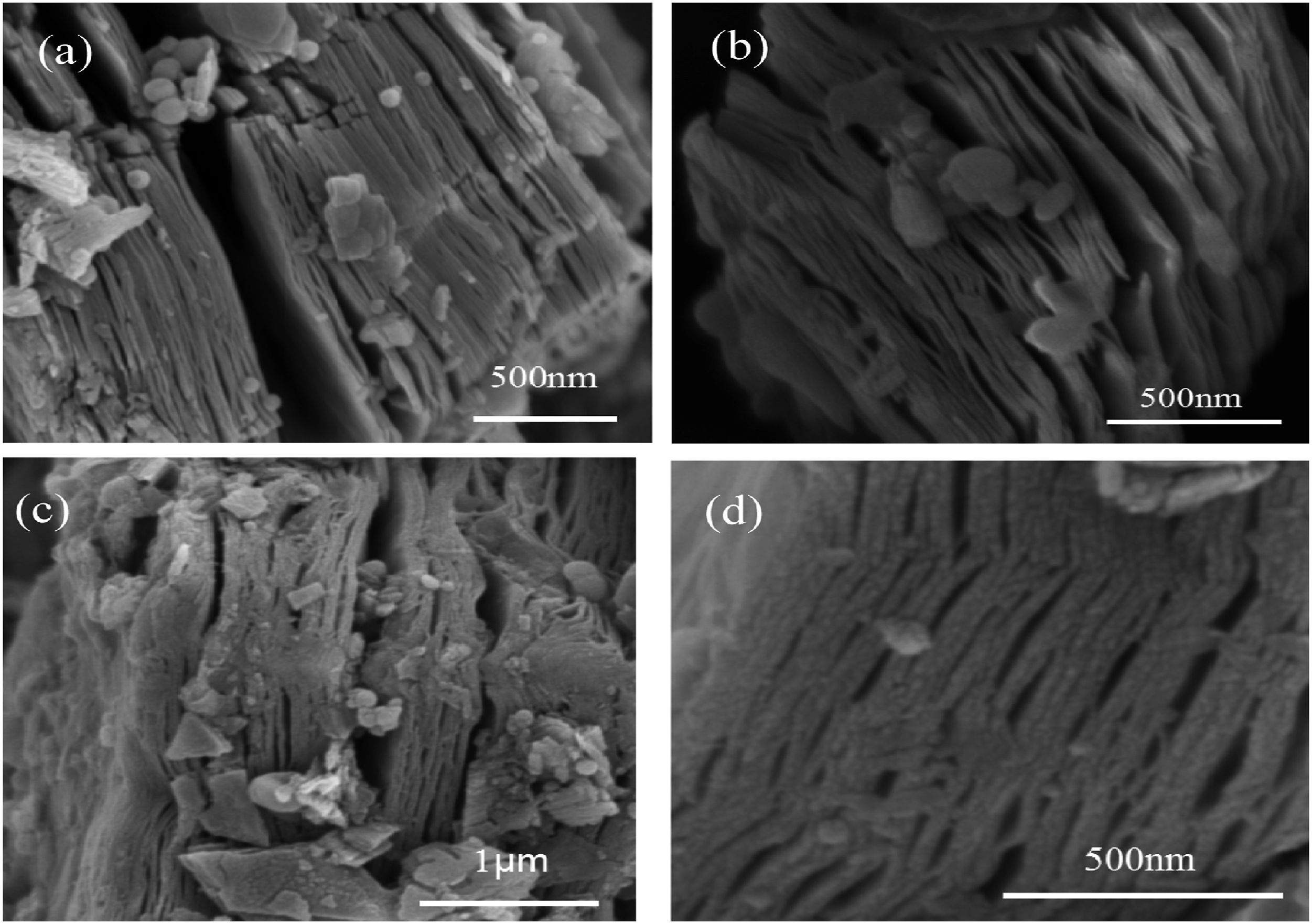
The enlargement view of Ti3C2Tx as presented in Figure 3(b), reveals a layered architecture. Nevertheless, in Figure 3(c), post PVA introduction, stacking together of sheets occurred due to hydroxyl within PVA reacting with −OH-terminated M-X surface (−OH + −OH = −O− + H2O) thereby forming Ti−O bonding at the surface, as affirmed by results garnered from XPS. Ti3C2Tx M-X@PVA nanocomposites enlarged view depicted in Figure 3(d) showcases an ordered layered architecture. 17
In order to further appraise the structural variations of Ti3C2Tx M-X post PVA embedment, the material was additionally characterized using TEM, as depicted in Figure 4. (a, d) 2-D nanosheets of Ti3C2Tx and M-X@PVA nanocomposites.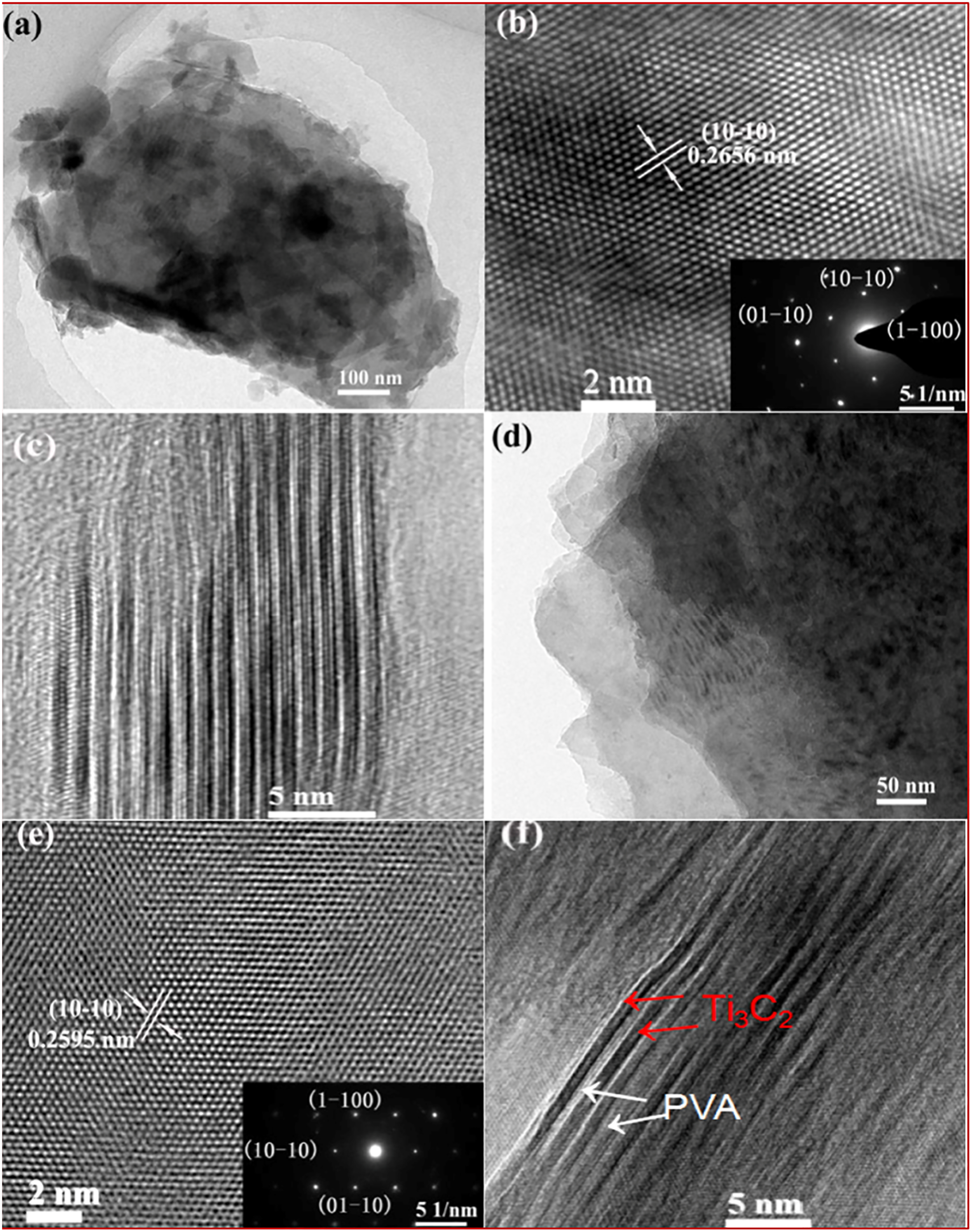
Figure 4 (a, d) display the 2-D nanosheets of Ti3C2Tx and M-X@PVA nanocomposites, respectively as exfoliated sheets were very flat and distributed as free standing layer or stacks of varying sheets. The inserted selected area electron diffraction (SAED) patterns displayed in Figure 4 (b, e) reveal that the M-X crystalline planes are hexagonally systemic, implying that PVA crystalline form is stable. Figure 4 (c, f) presents the multilayered Ti3C2Tx M-X and Ti3C2Tx M-X@PVA nanocomposites cross sections respectively, wherein the nanosheets are less evenly stacked within Ti3C2Tx M-X@PVA nanocomposites in comparison with Ti3C2Tx M-X attributed to prevalent polymeric reaction. 17
Morphological and structural trends of M-X@Fe3O4 and C@TiO2@α-Fe 2-D nanocomposites
M-X@Fe3O4 and C@TiO2@α-Fe 2-D nanocomposites have been fabricated using situ hydrothermally affiliated arrangement of Fe3O4 nanoparticulates on M-X nanosheets post-annealing.
18
M-X@Fe3O4 nanocomposites are built of evenly dispersed Fe3O4 nanoparticulates within the inter-layering of the 2-D M-X Ti3C2Tx nano-flakes. Figure 5 elucidates the morphological images of pristine M-X, specimen MF-3, and MF-3-A. Morphological images of pristine M-X, specimen MF-3, and MF-3-A.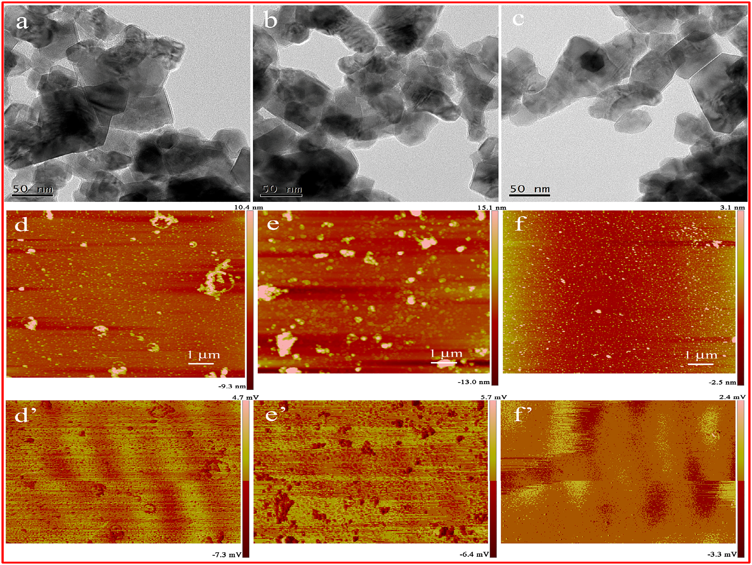
Figure 5(a) presents the 2-D M-X morphology of Ti3C2Tx, as the HRTEM image of Ti3C2Tx (Figure 5(b)) showcase the layered architecture of pristine M-X with ∼1.02 nm spacing. For sample MF-3 (Figure 5(c)), Ti3C2Tx is uniformly covered by spherical Fe3O4 nanoparticulates. Figure 5(d) presents specimen MF-3 HRTEM image with SAED patterns inserted. 18
This morphological architecture facilitates enhanced electromagnetic wave absorption presenting them as prospective materials to be utilized in the field of electromagnetic wave absorption. 18
Morphological and structural trends of Ti3C2Tx M-X@poly (N-isopropylacrylamide) p (NIPAm) and N-(2-hydroxylethylpropyl) acrylamide (HEAA) nanocomposites
A dual sheeted HDG actuator constituting of a photo-thermal sheet constructed from the embedment of Ti3C2Tx M-X within poly (N-isopropylacrylamide) p (NIPAm) nanocomposites and N-(2-hydroxylethylpropyl) acrylamide (HEAA) nanocomposites.
19
The even and efficient embedment of M-X within NIPAm nanocomposites were investigated. Figures 6 and 7 depicts various morphological elucidations of garnered nanoarchitectures. TEM images of fabricated nanoarchitectures.
19
SEM images of fabricated nanoarchitectures.
19
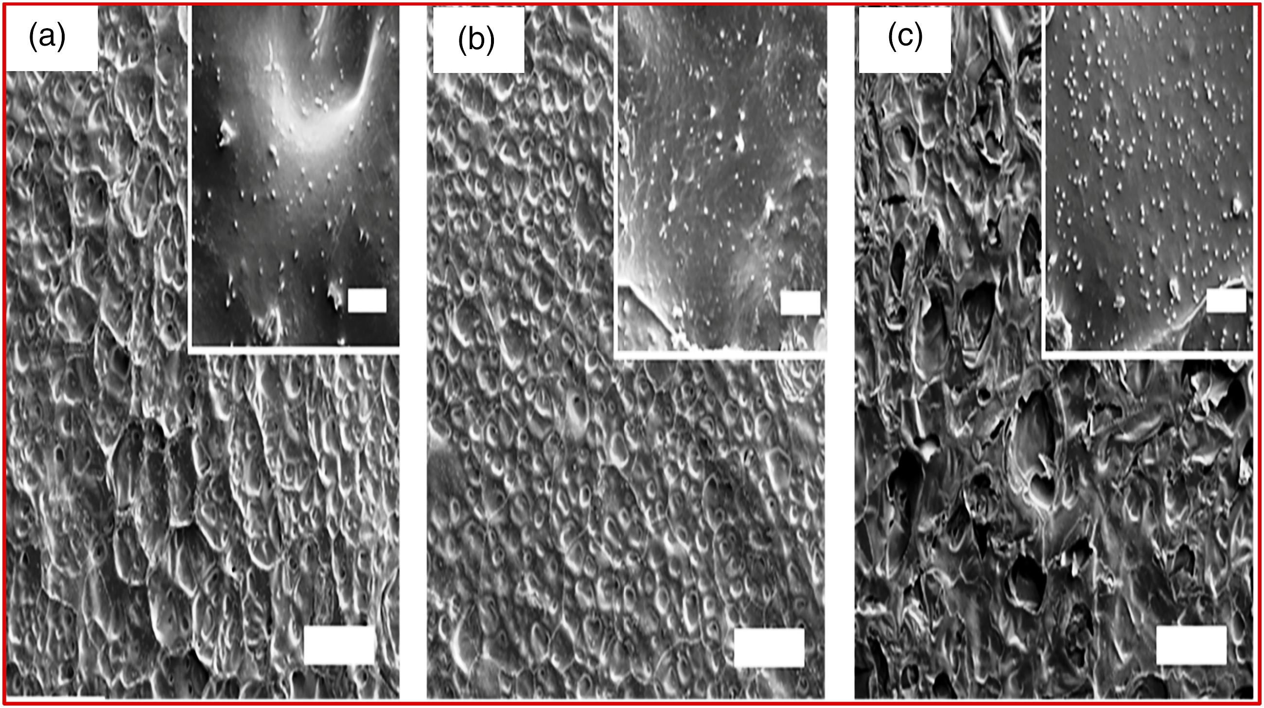
TEM and SEM images in Figures 6 and 7 respectively depicts exfoliated Ti3C2Tx. Certain flaws and deterioration are apparent on the M-X flake surface which is induced by LiF, which is the HCl etching solution, or partial oxidation of M-X. Hence, the exfoliated multi-layered Ti3C2Tx (ML@M-X) underwent delamination via extended sonication, as well as few Ti3C2Tx (FL@MX) layers were formed, as presented in TEM image depicted in Figure 6(c). 19 This morphological arrangement affirms usage in micro-fluidically light detecting devices. 19
Morphological and structural trends of Ti3C2Tx M-X@glass-fibers nanocomposites
In another investigation, conductive Ti3C2Tx M-X flakes underwent successful transfer to insulative glass fibers through oxygen plasma modification thereby enhancing adherence. 20 Escalating plasma modification power, time as well as coating layers result in decrement in M-X@ fibers electrical resistance.
In order to appraise influence of the size of M-X flake, films underwent fabrication from miniature and wide flakes through vacuum-facilitated filtration as well as Raman spectra (Figure 8A (a)). The TEM images (Figure 8A (b, c)) reveals varying sizes of lateral flakes of both small and enlarge flakes as well as diffraction trends. Bigger flakes were seen exhibiting EC of ∼3500 S/cm on fabrication of freestanding films, while miniature flakes displayed conductivity of 2200 S/cm within the film.
20
TEM image conductive Ti3C2Tx M-X flakes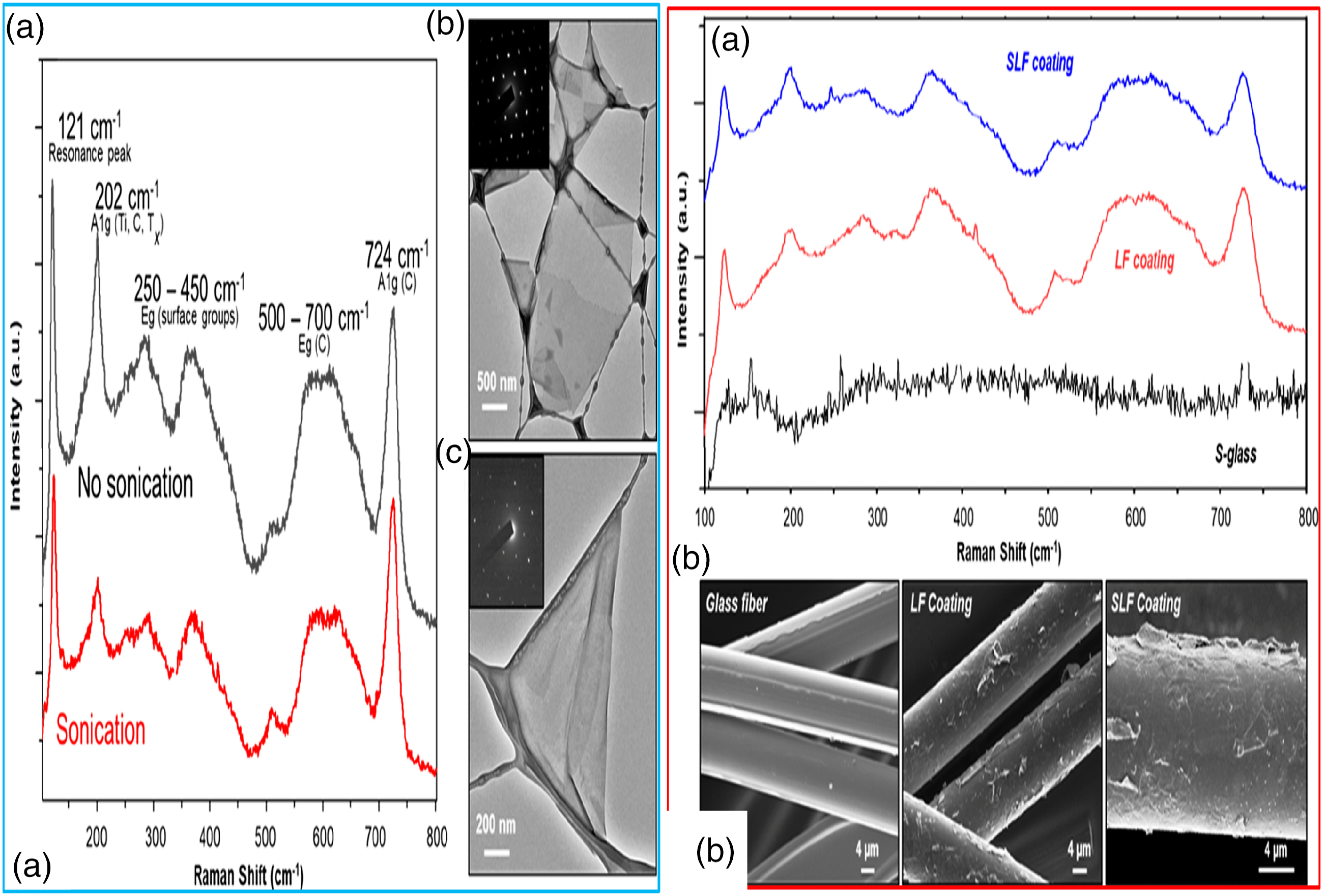
Figure 8B (a) presents the average spectra for both 5-dip LF and SLF-coated fibers. SEM images of fiber surfaces exposed satisfactory adherence and coating of Ti3C2Tx for both LF M-X coating strategies (Figure 8B (b)). M-X flakes are seen covering whole length of fibers devoid of glass surface visibility. In order to evaluate the coating evenness and its influence on electronic attributes, glass fibers underwent surface modification with differing oxygen plasma modifications. Figure 9 depicts the SEM image of the materials. SEM image of the materials.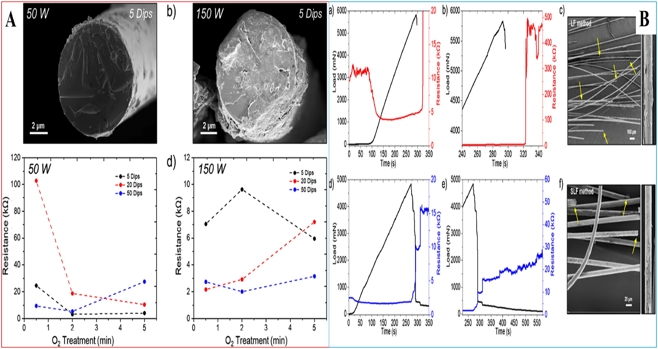
Figure 9A (a, b) present SEM images of plasma-modified fiber fractural surfaces at varying plasma power intensities (50 and 150 W) post five dipping within aqueous M-X distribution of broad flakes. The equivalent electrical resistance graphs of varying plasma power and modification duration are depicted in Figure 9A (c, d). 20
Figure 9B (a, d) depicts the resistance variation with incremental tensile load as a function of time for LF- and SLF-coated glass fiber bundles. Thus, tensile load gets close to 5–6 N close to break after ∼275 s, an increment in electrical resistance is reported as free standing fibers commences breakage within the bundle commences separation thereby interrupting the conductive route (Figure 9B (a, d)). Post tensile load dropped to 0 N at break (Figure 9B (b, e)), zero notable fracturing point was seen within fibrous substrates bundles, nevertheless electrical behaviors were stabilized. LF-decorated fibers utilizing five dipping revealed a sharp increment in electrical resistance briefly after tensile break subsequented by a short stabilization about 450 kW (Figure 9B (b)) prior to fast incrementing to resistance limit. SLF coating strategy exhibited a dual-step variation in resistance from ∼10 to 15 kW subsequented by a steady increment in electrical resistance. Nevertheless, a higher time during testing is required to attain the limit of resistance of the gadget (Figure 9B(e)). SLF-decorated fibers exhibited inferior resistance values post fracturing as a result of improved coating emanating from usage of both miniature and broad flakes of M-X. SEM images of distorted fibers (Figure 9B (c, f)) reveal free standing fibers breakage at varying locations (yellow arrows), inducing incremental resistance as distorted fibers gradually separate. 20
Morphological effects on properties and applications of MX@conductive composite fibers
In a study, a solvent exchange (SE) fabrication pathway was inculcated to produce non-oxidized as well as elevatedly delaminated Ti3C2Tx M-X distributions thereby offering a novel pathway for processing M-X nanoarchitecture, gadgets, and uses.
21
The dark grey d-M-X distribution was free of broad particulates consisting of single-layered and few-layered flakes as depicted in Figure 10 a with single sheet thickness of ≈3 nm as well as lateral sizes in differing micrometric scale.
21
TEM images and SAED patterns of d-M-X flake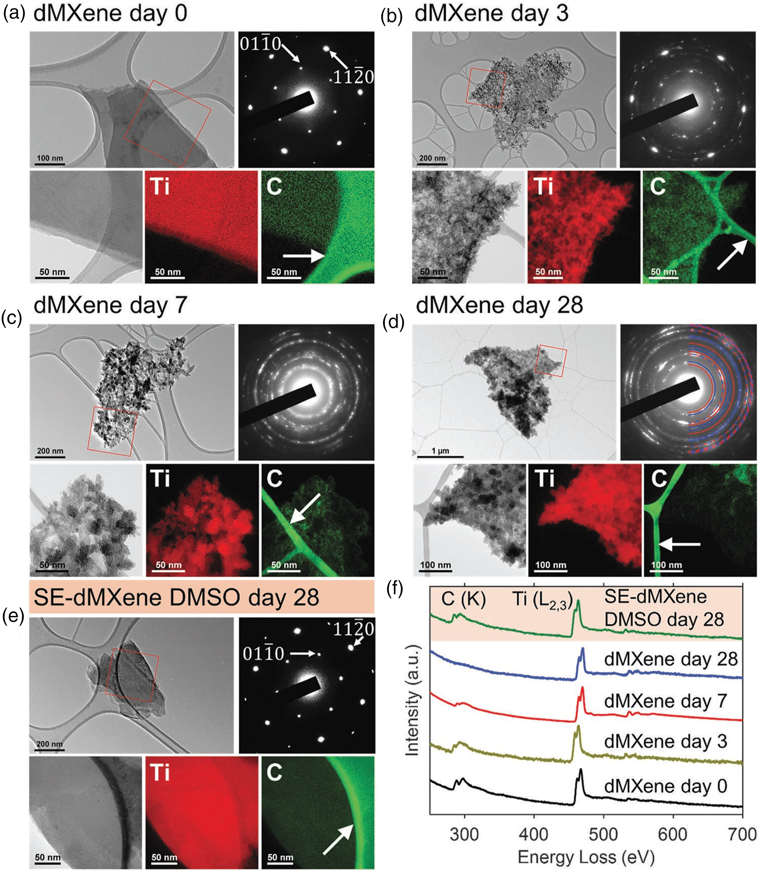
The SAED pattern of a representative d-M-X flake garnered utilizing TEM, revealed a trend of single crystalline substrate, appearing like a periodically arranged spots (Figure 10 (a)). Appraisal of the SAED patterns (Figure 10(d)) reported TiO2 presence rutile as well as anatase stage in accordance with garnered XRD results. 21
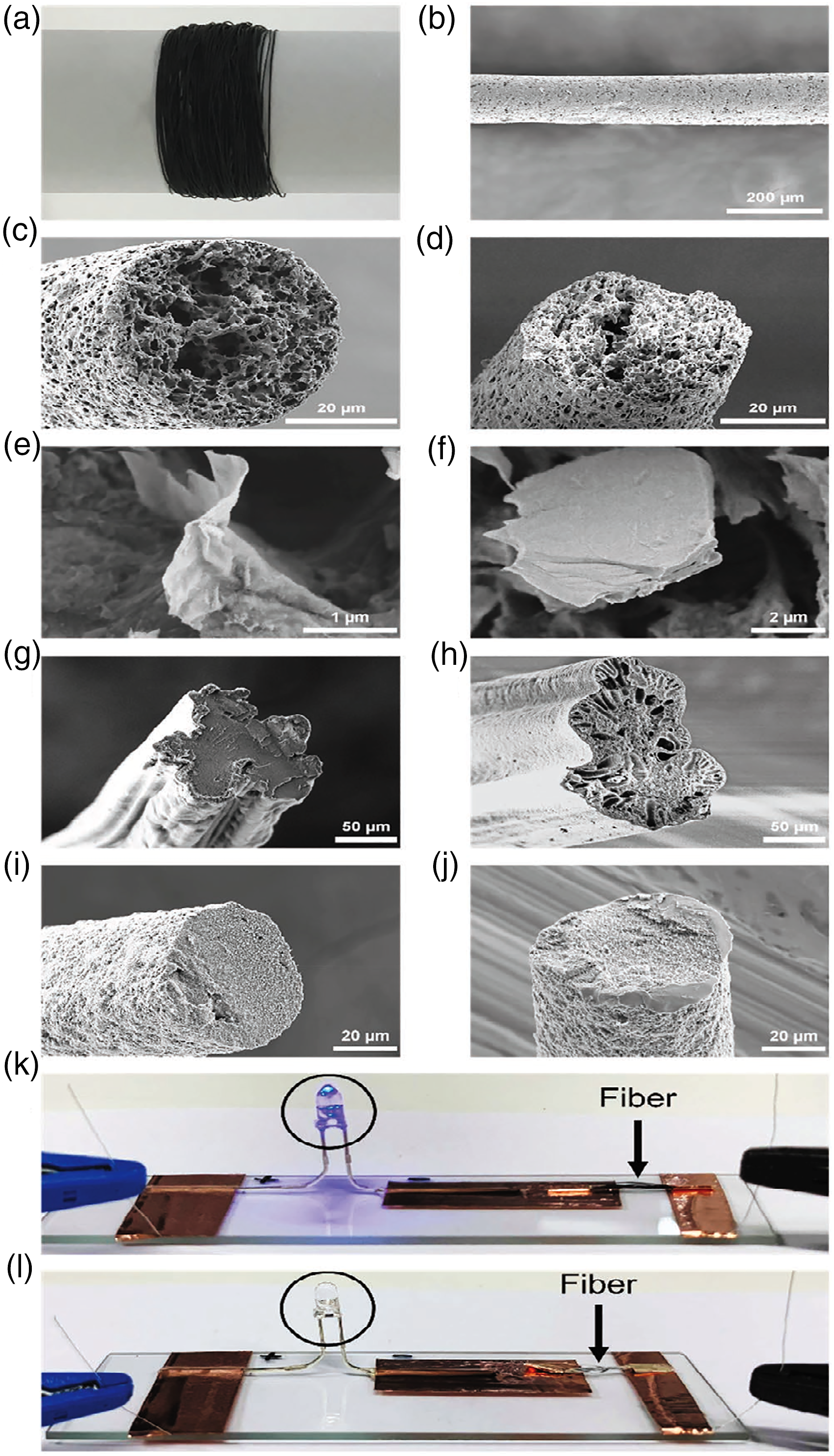
Wet-spinning strategy was utilized in fabricating M-X nanofibrous architecture using varying polymeric matrices including polycaprolactone (PCL, Figure 11(a–f)), polyacrylonitrile (PAN, Figures 11(g) and (h)) as well as polyvinylidene fluoride (PVDF, Figure 11(i, j)). The M-X distributions fabricated via solvent exchange (SE-dM-X) and re-distribution (RD-dM-X) pathways underwent initial mixing with the polymeric matrices with varying ratios (i.e. 1:10, 2:10, and 3:10) in DMF and then spun into fibers utilizing IPA as coagulation solvent. Though it was feasible fabricating fibers continuously (Figure 11(a)) utilizing both M-X distribution, the SE-dM-X resulted in very smooth and highly uniform fibers exhibiting enhanced distribution of M-X nanosheets within the polymeric matrix as observed in elevatedly magnified SEM images for PCL nanofibrous architecture (Figure 11 (e, f)).
21
Morphological inclination of PCL nanofibrous architecture.
21
Raman scattering characterization of M-X@sulfanilic acid-functionalization
The efficient functionalization and self-assemblage of M-X are essential for versatile range of NM applications. Herein, the agglomerates of sulfanilic acid-functionalized M-X referred as M-X@SO3H with three samples dyes at the interface of air–water which displayed the architectural and aggregation variations of the architectural films, utilizing Langmuir-Blodgett (LB) technology, and outstanding evenness and repeatability utilizing surface-improved Raman scattering (SERS) spectra. 22 The garnered lateral dimension of the particulates was about 100 nm. In a bid to appraise the nanoarchitecture of the fabricated MX@SO3H@dye films, AFM along with TEM techniques were applied. The garnered MX@SO3H@dye architectural films, exhibited thin film morphological inclination with agglomerates as reported from TEM images. AFM images were observed in varied agglomerate spheres in the fabricated MX@SO3H@dye architectural films, implying certain level of dye molecular entities with MX. 22
Morphological and structural characterization of M-X@poly (vinylidene fluoride-trifluoro-ethylene-chlorofluoroehylene) (P (VDF-TrFE-CFE)) nanocomposites
Poly (vinylidene fluoride) (PVDF)-situated percolate architectures have been fabricated utilizing 2-D M-X nanosheets as reinforcement and results revealed notably improved dielectric permittivity.
23
The poly (vinylidene fluoride-trifluoro-ethylene-chlorofluoroehylene) (P [VDF-TrFE-CFE]) polymeric material embedded within 2-D Ti3C2Tx nano-sheets attained a dielectric permittivity up to 105 close to the percolation limit of about 15 wt. % M-X inclusion, superseded the values of all polymeric carbon nanocomposites previously reported. Figures 12 and 13 depicts the SEM, TEM and structural dispositions of garnered nanoarchitectures. (a) TEM; (b) SEM; (c) Raman spectroscopy; (d) XRD; and (e) XPS studies of MX@P (VDF-TrFE- CFE).
23
(a) TEM image; (b) EDS mapping of MX@P (VDF-TrFE- CFE); (d) TEM of M-X nanosheets; (e) Raman spectroscopy; (f) FTIR of M-X@P(VDF-TrFE-CFE) nanoarchitectures.
23
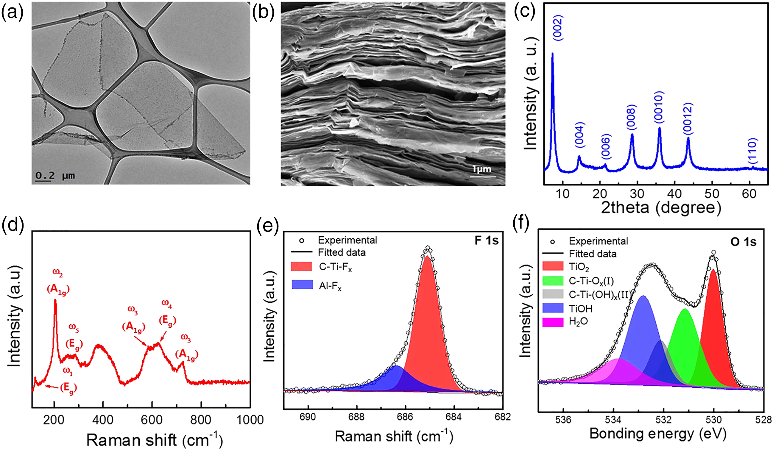
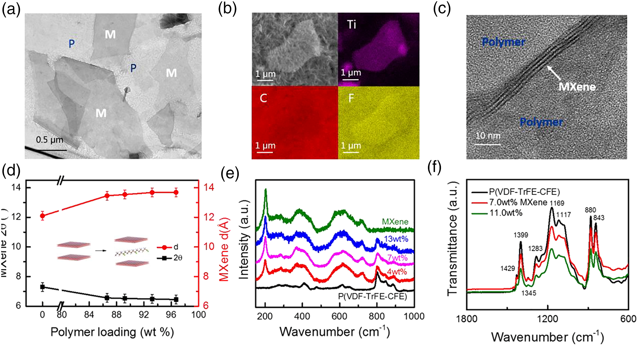
Figure 12(a) presents the morphological TEM image of a one-sheet M-X fabricated via sequential etching and delamination procedure. Additionally, the cross-sectional SEM image in Figure 12(b) depict the layered architecture of vacuum-filtrated M-X films. Raman spectroscopy as well as XRD were utilized in characterizing the M-X sheets. Ti3C2Tx presents a strong (002) XRD peak at 2θ = 7.2° corresponding to d-spacing of 1.2 nm (see Figure 12(c)). From Figure 12(d), Ti3C2Tx@CF Raman spectrum display strong peaks at 205 as well as 721 cm−1, assigned to Ti3C2O2 modes. 23
In addition, XPS was utilized in characterizing the specimens surface chemistry. From Figure 12(e), high resolution XPS spectra of specimens in the region of F 1s (685.1 eV) revealed that the Ti3C2Tx specimens are composed of both F-terminating entities Ti and AlFx. From Figure 12(f), the O 1s peak can undergo fitting utilizing four symmetrical peaks at 530, 531, 532.2, and 532.8 eV, equivalently corresponding to TiO2, C−Ti−O x, C−Ti− (OH) x, and TiOH. 23
Figure 13(a) shows the TEM image of MX@P (VDF-TrFE- CFE) architectural flakes which distinctly shows that M-X sheets are irregularly distributed within the polymeric matrix. In the energy dispersive spectroscopy (EDS) mapping (Figure 13(b)), titanium (Ti) prevalence is apparent within the M-X sheet at the central zone of the P(VDF-TrFE-CFE) matrix, while C and F are dominating the entire zone.
A cross-sectional TEM image of M-X nanosheets of three layers’ thickness distributed within the polymeric matrix is presented in Figure 13(c). 23 Figure 13(d) presents the XRD studies of M-X@P(VDF-TrFE-CFE) architectures with varying polymeric inclusions. Obviously, with incremental polymeric inclusion, expansion of M-X interlayer spacing occurs. A feasible elucidation of this result involves intercalation of certain polymeric chains between M-X layers. This intercalation may have been facilitated by the functional entities on surface of M-X such as F, O, and/or OH), capable of interacting with atomic entities (e.g. H) upon P(VDF-TrFE-CFE) chain network. 23
M-X Raman spectroscopy of P(VDF-TrFE-CFE) nanocomposites underwent appraisal, as Figure 13(e) elucidates the equivalent data. Inherently established peaks of the architectures are composed of pristine M-X and ter-polymeric peaks suggesting zero vibrational variations during the comingling steps. From Figure 13(e), the major M-X peak intensity occur at 205 cm−1 with incremental M-X inclusion. Figure 13(f) depicts the Fourier-transform infrared spectroscopy (FTIR) elucidation for polymeric architectures composed varying M-X inclusions within the mode of transmission. 23
Morphology and structural of MX@CP asymmetric pseudocapacitors
2-D titanium carbide (Ti3C2Tx), M-X, has been utilized as a versatile pseudocapacitive anode gadget for a number of CPs, including polyaniline, polypyrrole, and poly (3,4-ethylenedioxythiophene) decorated on reduced graphene oxide (rGO) sheets. 24
SEM images of CP@rGO hybrids displayed macroporous irregular shape of the decorated CP. The SEM and TEM images of Ti3C2Tx M-X exhibit 2-D morphology, such that M-X film is constituted of completely arranged stacked sheets. 24 FTIR and Raman spectroscopies were further utilized in confirming the decoration of the doped CP on rGO sheets. Raman spectra of the PANI@rGO, PPy@rGO, and PEDOT@rGO respectively reveal a vast range of nanoarchitectured CPs with versatily prevalent M-X as anode and cathode substrates, respectively, for further performance improvement of ESD. 24
Morphology and structure of carbon@M-X derived from M-X@polypyrrole nanocomposites as oxygen reaction minimization electrocatalysts
Metallic-free Noble catalysts (MNC) have garnered great interest as prospective material for Pt-focused catalyst replacement for advanced uses linked with oxygen reduction reaction (ORR), essential for broad-range renewable energy storage as well as conversion. Thus, a work dwelt on synthesization of MNC composed of porously N-rich carbon@M-X, garnered utilizing extremely conductive as well as reactive Ti3C2 M-X and PPy as a C and N origin. Garnered electrocatalysts demonstrated outstanding electrocatalytically inclined activities as well as stability with an onset and a half-wave potentials equivalent to 0.85 and 0.71 V, respectively. Garnered results from this investigation showcase feasibility of designing efficient MNC usable with other chemical structures. 25
M-X@PPy SEM showcases a uniform PPy dispersion within the M-X surface. Here, pyrolysis modification did not vary the layered architecture of the catalysts. SEM and TEM images reveals the prevalence of M-X layers, implying continual exfoliation of the M-X Ti3AlC2 architecture. M-X sustained its layered architecture post occurrence of PPy surface polymerization and carbonization. Nevertheless, the elevated angle annular dark-field (HAADF) micrographics as well as equivalent energy dispersive X-ray (EDX) mapping of free standing nanoplate of the M-X@PPy-800 specimen affirmed uniform dispersion of C and N on the M-X nanoplate, the prevalence of which was exposed by the Ti-rich environment. 25
HRTEM revealed regions displaying lattice fringes, likely belonging to M-X located 0.408 nm apart, attributed to of Ti2C3 (001) plane. Moreover, inverse of Fast Fourier Transform (FFT) image of selected region reveal a disorderly turbo-stratic carbon nano-regions of MX@PPy-800 inducing creation of free volume and micro-porosity within the carbon architecture revealing insight into created crevices and voids. The N2 adsorption-desorption isotherms and DFT pore dimensional distribution revealed a hierarchically inclined porosity as well as broad surface region. 25
Morphological and architectural effects on properties of M-X@polymeric nanocomposites
M-X conductivity
M-X exhibit elevated metallic conductivity, with Ti3C2Tz spin cast films exhibiting conductivities in range of ∼10,000 S/cm. 26 M-X embedment within polymeric matrices facilitates the fabrication of conductive nanocomposites usable as shields against EMI as well as radio frequency interference, specified molecule and gas sensing devices, flexibility strain sensors, as well as storage and energy conversion applications. Hence, in a study epoxy/M-X combination referred as EP@Ti3C2Tx@M-X nanoarchitecture was constructed and investigated for electrical conductivity (K) under varying inclusions of Ti3C2Tx M-X nanosheets. 26 EP@Ti3C2Tx@M-X nanoarchitecture electrical conductivity (K) gradually incremented with incrementing inclusion of the filler (Ti3C2Tx). 26
Interfacial strength
Usually, the effect of M-X nanoarchitecture reinforcement is significant due to increment in interfacial interaction between the flakes as well as the enveloping polymeric matrices. 27 Nevertheless, this interaction is scarcely appraised, whilst the enhancement in material attributes is evidenced of improved interfacial interactions/strength.28,29
Barrier properties
M-X impermeable disposition result in enhancement of barrier behavior of polymers, thereby inhibiting permeating gases and miniature molecules. Polymeric nanocomposites reinforced using layered silicates as well as GN have reportedly sharply enhanced barrier attributes in comparison with their pristine polymeric contemporaries. 30 This phenomenon has been ascribed to the tortuosity model, elucidating feasibility of small molecular diffusion to trend a prolonged, highly tortuous route about impermeable reinforcement particulates. When these particulates exhibit elevated aspect ratios, thence can the path of diffusion become increasingly longer compared with unreinforced polymeric matrices . 30
Electromagnetic interference shielding efficiency
M-X and MX@conducting polymeric (M-X@CP) hybrid nanocomposites inherent conductivity, flexibility, miniature thickness and tunability, facilitates their usability for electromagnetic interference (EMI) shielding applications. Polymeric nanocomposites displaying both elevatedly efficient EMI shielding and heat dissipation have garnered high interests, though some challenges persist caused by the minimal film thickness as well as reduced reinforcement. 31 Thus in an investigation, a set of CS@MX nanoarchitecture films were prepared via layer by layer hierarchical technique and displayed high heat dissipation (6.3 W m−1 K−1), optimal EMI SE of 40.8 Db (35-μm thickness), high specific EMI SE (SSEt) (10, 650 dB cm2 g−1), in addition to outstanding Joule heating capacity, thus achieving satisfactory EMI shielding and heat dissipation applicable for electrical gadgets. 31
M-X and M-X@polymeric nanoarchitecture applications
The multifunctionalities of M-X have garnered versatile applications. M-X inherent elevatedly YM, satisfactory EC as well as surfacial chemistry variations are beneficial to nanocomposites, whereas their inherently adjustable bang gaps, and chemical stabilization, gears towards catalysis as well as energy storage applications, including fuel cells, lithium ion batteries (LIBs) and hydrogen storage.32,33 Potential results have been garnered in varieties of areas from opto-spintronically inclined usages 34 as well as flexy/wearable electronics gadgets 35 to environmentally and biomedically affiliated segments.36,37 M-X based materials in some of these studies, performed quite outstandingly in comparison to existing contemporaries especially in the fields of EMI in aerospace along with electronically affiliated components,38–40 surface-improved Raman scattering materials 41 as well as energy storage structures.42–44
M-X and M-X@polymeric nanocomposites for energy storage
The depletion of fossil fuel and escalating cost of energy usage have induced high interest in renewable energy origin, storage and conversion structures, 45 including supercapacitors and batteries. Whereas the former exhibit high specific capacities, good for compact volume usage (inculcated within miniature electronics, including smartphones along with tablets), high power densities along with rapid charge–discharge rates are demonstrated by the latter usable in mobile applications. 46
M-X and M-X@polymeric nanocomposites for batteries
Nowadays, Li-ion batteries (LIBs) are versatily utilized in feeding miniature electronic gadgets as a result of their inherently elevated energy densities, satisfactory cycling behavior, and ecobenign inclination. 47 The emergence of elevated energy density electrode materials is imperative for next genre of LIBs. 48 Thus, M-X and M-X@polymeric nanocomposites have demonstrated great prospects for this usage, 49 ascribed to their specific surface areas, elevated electronically affiliated conductivities, and Li storage susceptibilities with minimal circuit voltage. Thus, the lithium ions diffusional barrier of Ti3C2 is at least five times miniaturized in comparison with TiO2 anatase and graphite usable materials.
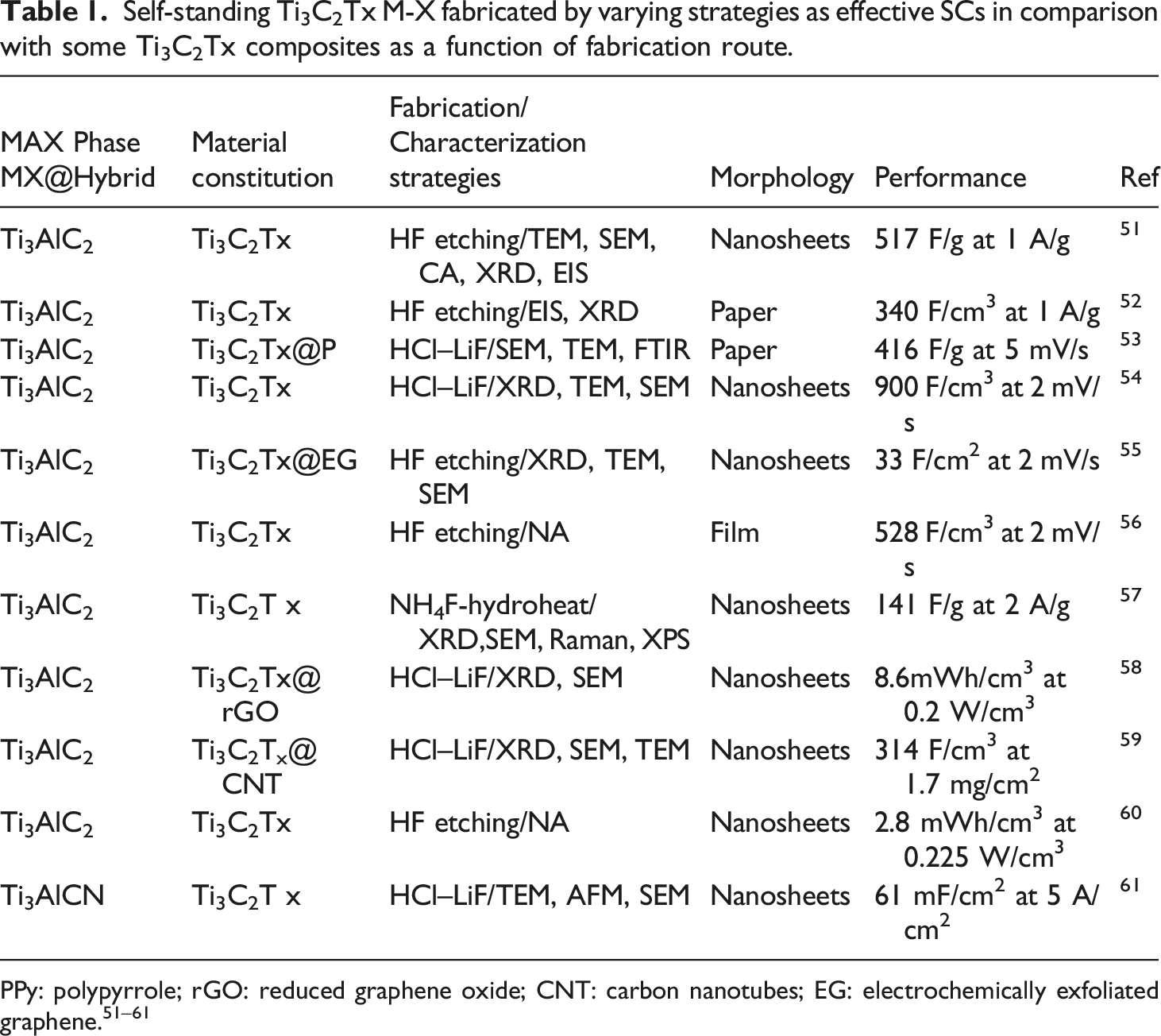
M-X and M-X@polymeric nanocomposites for supercapacitors
Self-standing Ti3C2Tx M-X fabricated by varying strategies as effective SCs in comparison with some Ti3C2Tx composites as a function of fabrication route.
M-X and M-X@polymeric nanocomposites for hydrogen evolution reactions catalysts
Escalating quests for elevatedly efficient and renewable acumen of energy production and storage for transportation usages have resulted in increased inquest into molecular hydrogen (H2). This molecular carbon-free fuel (non-fossil fuel) are liably manufactured, for example, via hydrogen evolution reactions through electrocatalysis, 62 Varying electrocatalysts for HER have been investigated, including conventional noble metallic including platinum as well as metallic-free catalysts phosphorene and graphitic carbon nitride. However, these materials still display inferior charge transfer, poor active location accessibility as well as elevated manufacturing prices, hindering their practical applications. 63 Thus, the emergence of highly stabilized, conducting, active and inexpensive catalysts for HER is essential. 64
Emerging attention given to M-X for catalysis is garnered from their metallic disposition, elevated carrier mobility as well as broad surface area/active sites, facilitating the electrocatalytic reactions due to rapid electron mobility. 65 Nevertheless, as a result of hyper-low work functionality, M-X and architectures are utilized as facilitating materials, manipulating the disposition of multicomponent electrocatalysts structures. 66 Finally, in spite of electrocatalysts susceptibility, M-X are potential materials for photocatalysis such as solar hydrogen as well as hydrogenation of carbon dioxide. 67
M-X and M-X@polymeric nanocomposites for sensors and membranous uses
M-X utilization for membranous applications are still evolving. 68 As a result of charge-selective ionic mobility, M-X membranes are sensitive to intercalative ions varying their layered distances through molecular/ion sieving strategy. 69 Herein, functional entities are critical to this response. Studies conducted on Ti3C2Tx coatings have reported outstanding performances towards bactericide such as E. coli and B. subtilis, specifically post membrane oxidation. 70 M-X hydrophilicity is beneficial for water treatment as well as separation for instance in desalination. 61 M-X membranes also exhibit elevated water-flux with outstanding rejection of salt (∼99.5%), more than polymeric, inorganic as well as 2-D graphene oxide (GO) membranes. 71 M-X have been appraised for sensors with elevated prospects in detection of environmental issues as well as biomedically inclined detective operations, including relative humidity, adrenaline, enzymes, gases, adsorption, cancerous bio-markers, neural functionalities, and so on. These attention is derived from their metallic conductivities, biocompatibilities, numerous adsorption locations as well as unique distribution in aqueous phases, capable of resulting in inferior electrical noise and detecting limit as well as elevated signal, and elevatedly sensitive sensors.
Effect of morphology on mechanical properties and applications of M-X and M-X@polymeric nanocomposites
Ti3C2Tx@M-X Young’s modulus (YM) is reportedly 333 ± 30 GPa, which is the highest amongst solution-processable 2-D materials. 72 Irrespective of molecular dynamic simulations reportage of YM of 502 GPa for Ti3C2Tx@M-X, surface modifications along with flaws result in minimized experimental values. Usually, mechanical reinforcement in nanofillers is significant in case of elastomeric matrices, as contrasting between reinforcement and matrix stiffness is significantly obvious ascribed to shear deformation as well as stress transfer to reinforcement particulates. Furthermore, anisotropic particulates may undergo alignment under elevated strain, as this strain-propagated alignment facilitates these platelet appearing particulates acting like fibers in conventional fiber-filled architectures. As crack inducement is energy consuming, specifically as all involved platelets undergo perpendicular alignment towards crack initiation, increment in elastic moduli as well as tensile strengths are increased.
EP@Ti3C2Tx@M-X nanoarchitecture mechanical disposition towards tensile and impact strength was appraised via an electronically inclined tensile testing machine. 73 EP@Ti3C2Tx@M-X nanoarchitecture tensile strength (a) and impact strength (b) as a function of increasing concentration of Ti3C2Tx@M-X revealed that inclusion of 1.2 wt.% Ti3C2Tx M-X, increased tensile strength and impact strength (66.2 MPa and 24.2 kJ/m2) respectively, which is attributed to inherently rigidness of polymeric chains. Thus, increasing inclusion of Ti3C2Tx M-X, induced increased rigidity of EP@Ti3C2Tx nanocomposites because of Ti3C2Tx M-X which linked varying free standing EP polymeric chains by –F, –OH, and –COOH functional entities. 74
M-X surface is broad enabling the functional entities to efficiently immobilize on the surface. M-X has shown extensive feasibilities for sensing uses as a result of elevated electric conductivity as well as minimal electron transfer inhibition. M-X can be utilized for biosensing devices due to inherent properties including morphology, broad surface area, satisfactory electrical conductivity, ease of functionalization as well as biocompatibility. M-X@polymeric hybrid nanoarchitectures normally exhibit enhanced properties in comparison with pristine polymer, such as mechanical properties, responsiveness as well as flame retardancy.132,135
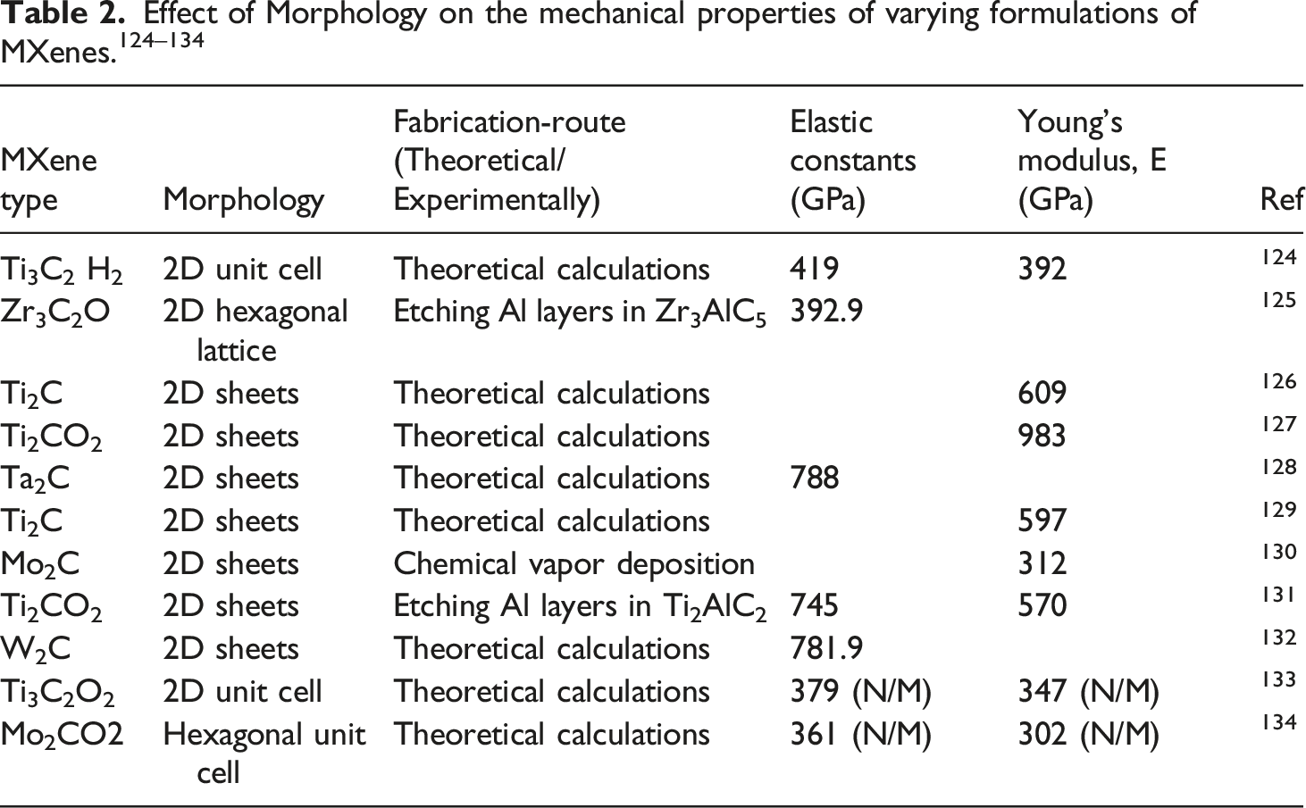
Monolayer sheet M-X height is 2.7 nm, whereas a folded architecture exhibits a 1.5 nm interlayer distance, higher compared with graphene. 136 This broad inter-sheet distance takes care of the outstanding M-X performance when utilized as active materials in sodium-ion batteries. Relative to mechanical properties, computational strategies are utilized in studying M-X mechanical properties as per surface functionalization, thickness, as well fabrication of nanocomposites. 137
Fracture mechanism of M-X polymeric nanoarchitectures
Studies of the mechanical properties of M-X@polymeric nanoarchitectures have been conducted.138,139 Elastic characteristics were experimentally garnered through nano-indentation using the tip of AFM, whilst the garnered elastic modulus was 0.33± 0.03 TPa. 140 As per classical molecular dynamics simulation, 141 which does not consider differing material deficiencies, the modulus increased and equaled 0.502 TPa, with M-X exhibiting elevated bending stiffness. 141
Hence, a study has evaluated the micromechanical attributes of M-X nanosheets via the fabrication of finite element (FE) relying on computational approaches, with major aim of evolving an FE model composed of a single sheet M-X nanosheets displaying a specific variation of individual sheets for analysis; along with identification of material factors via FE simulation of interfacial shearing. 142 The new knowledge here is fathoming deformation as well as failure mechanisms of M-X, and provision of a foundation for future designing of polymeric architectures filled with M-X nanosheets, and the fabrication of M-X@polymeric coatings with elevated-density M-X–M-X interactions. 142
Here, FE models were developed and used in predicting the mechanical behavior of M-X nanosheets. Utilizing LS-Dyna Explicit software, a finite element model was evolved for simulating the nano-indentation procedure of a 2-D M-X (Ti3C2Tz) single-layer flake and validation of the designed model. 142 The adhesive strength of the free-standing M-X film was determined through use of the model composed of one-layered M-X nanosheets with a peculiar number of free-standing flakes, as reverse engineering technique with a curve fitting technique was utilized. The in-plane stiffness, inter-laminar shear strength, as well as shear energy releasing rate of the M-X film underwent prediction using this strategy. Results emanating from sensitivity evaluation revealed that the inter-laminar shear strength and in-plane stiffness displayed the highest effect on the mechanical disposition of M-X film under tension, as the shearing energy releasing rate mainly influences the inter-laminar deterioration properties of nanosheets. 142
The main aim of this pre-simulation entailed the formation of an FE model of M-X lone-layered sheet for evaluating nano-indentation step in LS-Dyna software while using the force versus deflection curve in validating the FE model along with the material attributes. Figure 14 depicts the FE model fabricated according to experimental data generated by Lipatov et al.
142
Finite element (FE) model for appraising nano-indentation process.
142
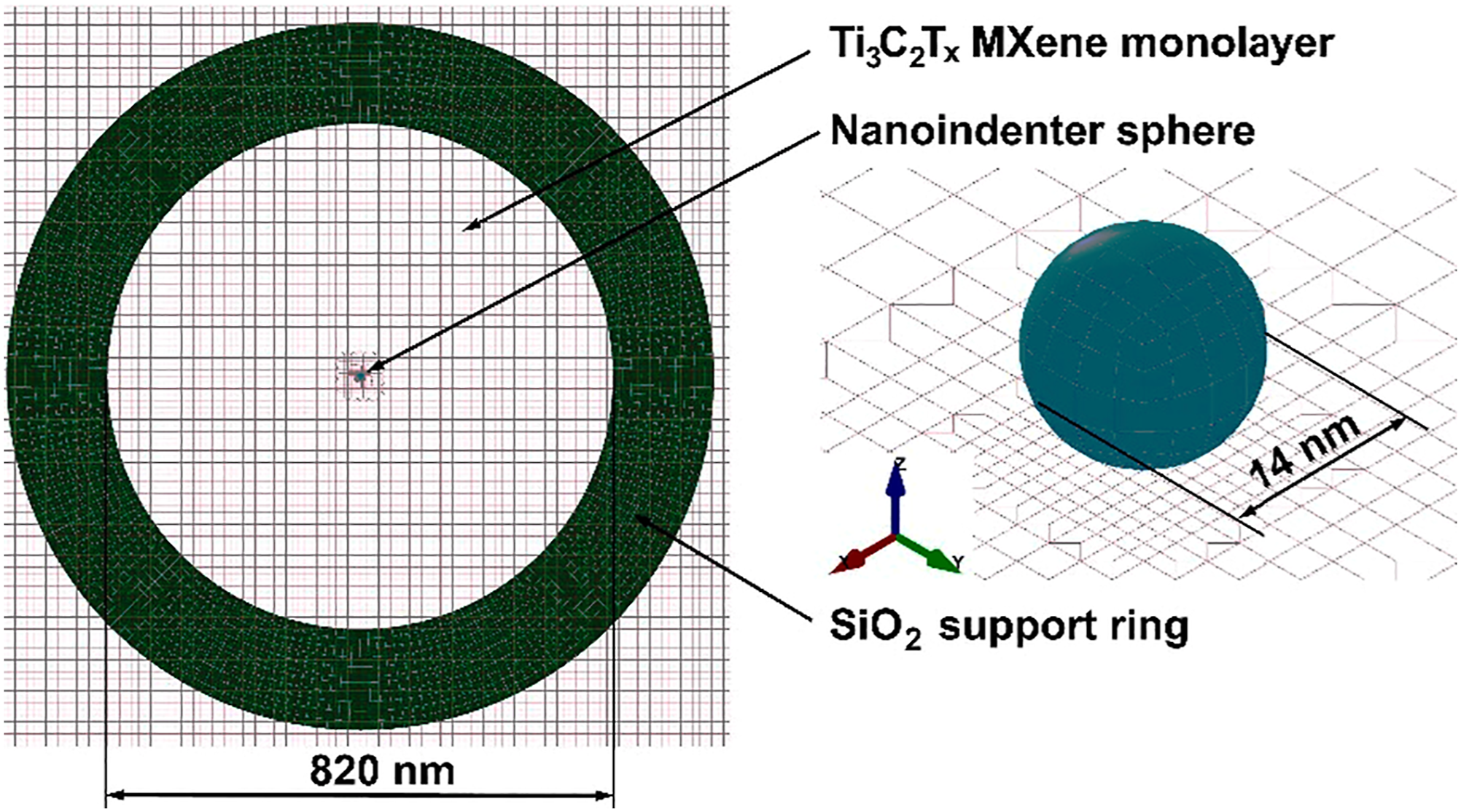
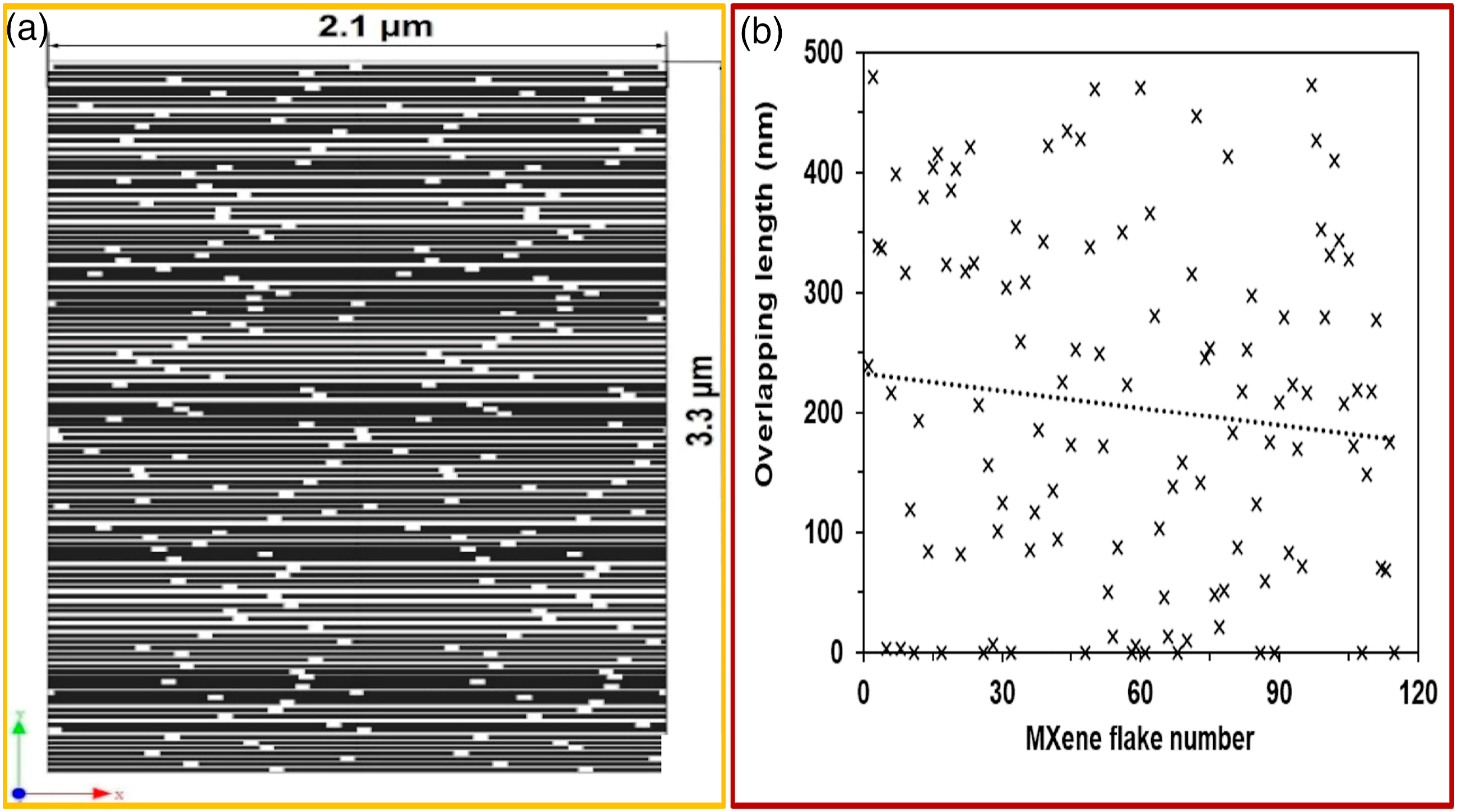
Here, it was assumed that the M-X flake display isotropic features, and thus, the membranous material can undergo parametrization utilizing the Young’s modulus, E and Poisson’s ratio, v. The thickness of Ti3C2Tz single-layer flake is critical parameter which affects the results of nano-indentation evaluations. Utilizing AFM for determining thickness of single-layers of 2-D materials present some hindrances. Nanosheets overlapping display a critical effect on the strength of the interlayer surface. Thus, a 2-D evaluation of randomly positioned rectangle nanosheets was conducted utilizing Digimat, a software for modeling materials. Regarding the overlapping appraisal, M-X nanosheets having dimensions of 1000 × 20 nm were used. The total thickness of M-X film created from these nanosheets was 3.3 m, garnered during the testing
142
(Figure 15(a)). Emanating results reveal that the average overlapping of nanosheets is 20% (Figure 15(b)). This overlapping number was utilized in creating the FE model. Estimation of overlapping nanosheets: (a) A segment of the Digimat model for free-standing M-X film, (b) generated overlapping length estimated by simulation of the positioning of unaligned nanosheets.
142
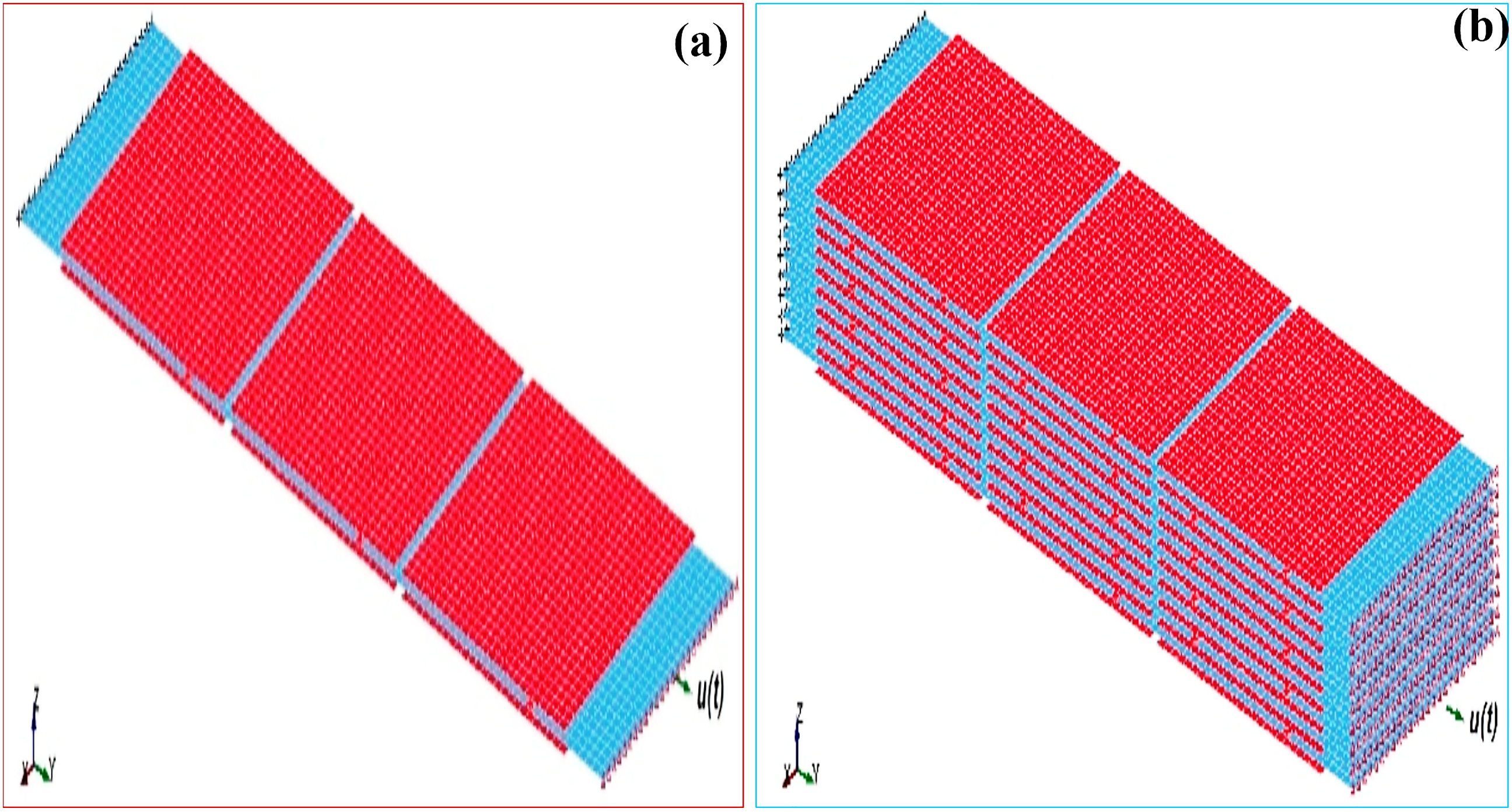
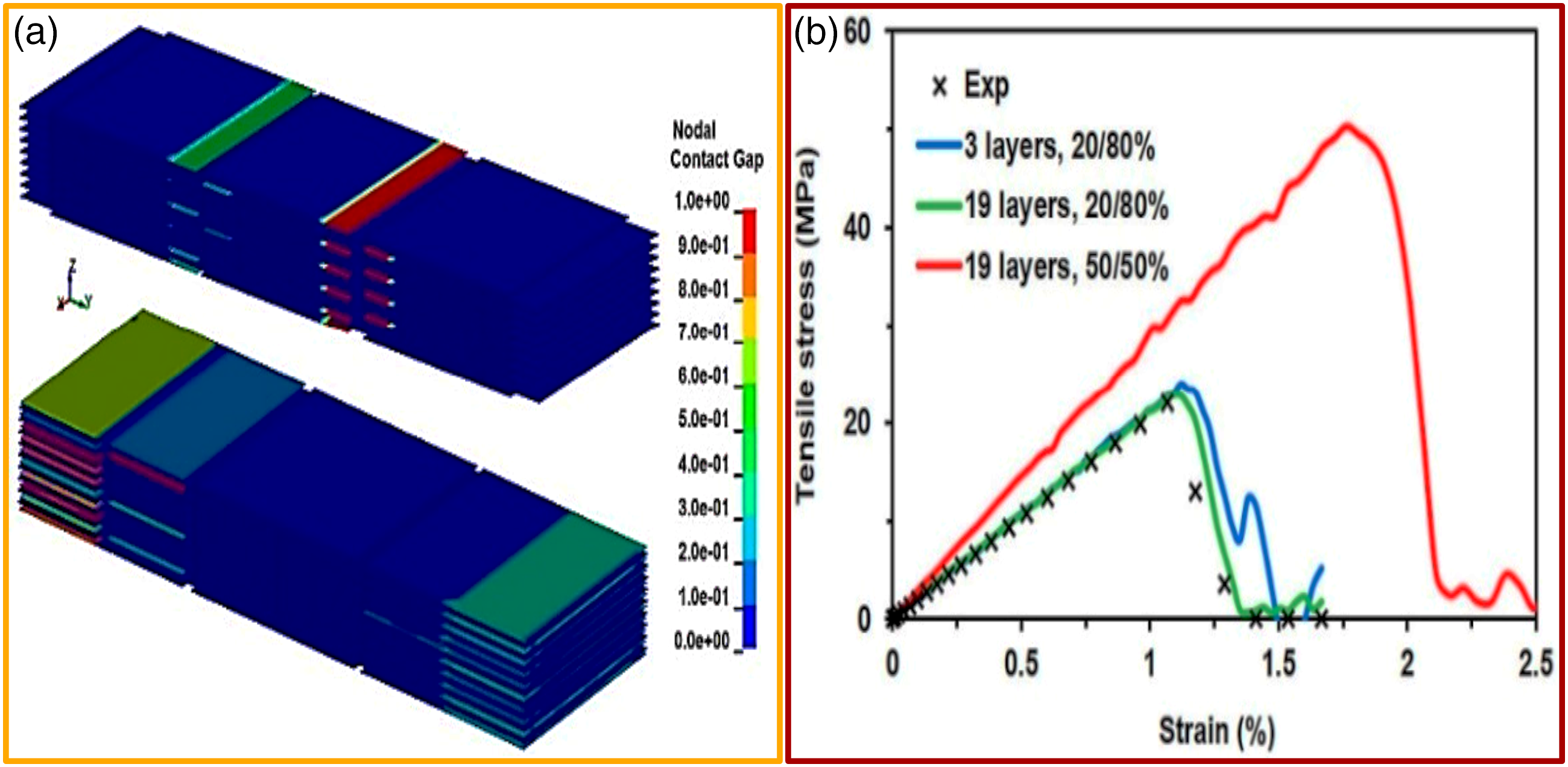
In order to attain FE simulation of the interfacial shear strength of M-X nanosheets (1000 nm 1000 nm 20 nm), three- (Figure 16(a)) and nineteen- (Figure 16(b)) layer models were developed with an overlapping length of 200 nm (20%).
142
Interfacial shear strength FE model of M-X nano-sheet for simulating 20% over-lapping length: (a) 3-nanosheets-thick model, (b) 19-nanosheets-thick model. Red and blue colors are used for contrast for elevated displaying of single-layered nanosheets.
142
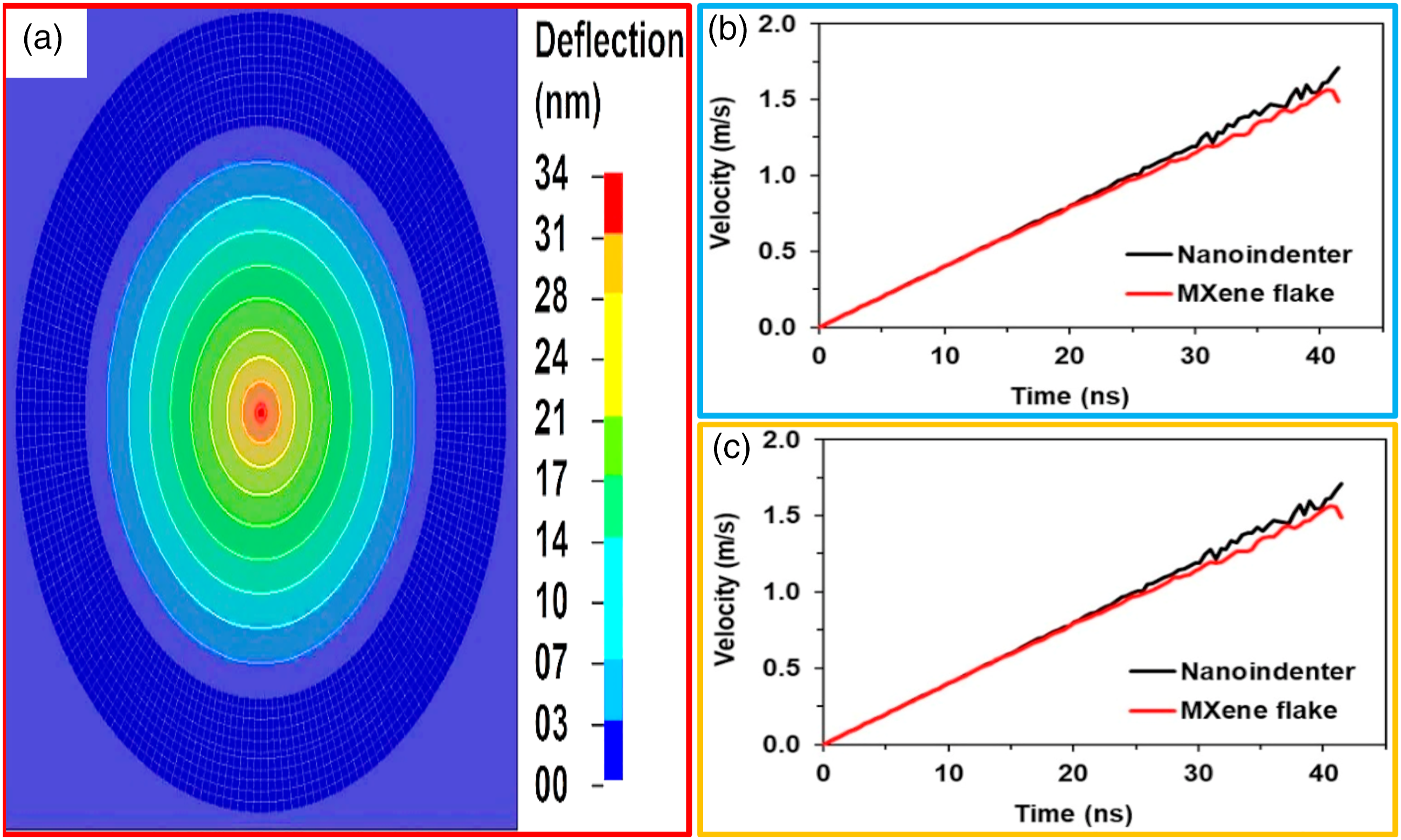
The simulated deflection field of the indented M-X single-layer flake is displayed in Figure 17(a). The most elevated deflection of 34 nm was attained at the central point of the M-X flake. The velocity dependence of the nano-indenter as well as the central point of the M-X single-layer flake on time display a linear disposition (Figure 17(b)). Evaluating the deflection of the nano-indenter and the central point of the M-X single-layer flake dependence on time, the function is notably non-linear (Figure 17(c)).
142
Simulated deflection field of the Ti3C2Tz M-X single-layer (a). FE results of the nano-indentation simulation: (b) nano-indenter velocity and the center point of M-X single-layer flake, (c) nano-indenter deflection and the center point of the M-X single-layer flake.
142
The parameters of the material revealed by FE modeling focused on 20% average random overlapping of nanosheets. Hence, in the FE model validated, the nanosheets overlapping was varied by about 50% and the behavior of the ideal overlapping scenario evaluated (Figure 18(a)).
142
In accordance with garnered FE simulations, the force versus displacement relations underwent transformation to stress–strain curves and compared with the experimental tensile curve (Figure 18(b)). Thus, results garnered from the simulation, relying on previously selected material parameters as well as optimal overlapping of about 50%, in comparison with the tensile curve attained experimentally, showcase increment of the free-standing Ti3C2Tz film strength, stiffness, and failure strain on incremental overlapping. Thus, it is distinct (Figure 18 (b), red curve) that the nanosheets random overlapping minimized the strength as well as stiffness of films garnered from free-standing M-X nanosheets.
142
(a, b) Validated FE model.
91
Hence, the FE models haven curve fitted techniques can be utilized for material constants along with identification of adhesion energy. Hence, only appropriate statistical appraisal of the geometric parameters of the nanosheets is required. 142
In a related investigation, a computational evaluation of the mechanical as well as damage behavior of new hybridized polymeric nanoarchitectures with GN and M-X nano-fillers has been conducted for flexible electronics gadgets and advanced ultra-strength architectural uses with additional functions, including actual control of structural integrity.
142
Here, geometrically affiliated models of 3-D representative volume entities of differing orientations were generated, whilst a computationally affiliated model founded on micromechanical finite elemental technique was developed and panacea utilizing an explicit dynamically inclined solver. The results garnered present insights into the mechanical along with damage disposition of the postulated architectures while providing insight into further design initiatives for equivalent multifunctional materials.
142
The distribution of stress in RVEs exposed to tension towards the x-axis direction are presented in Figure 19 whereas the damage propagation pathway is presented in Figure 20.
142
Stress distribution within RVEs showcasing crack creation and propagation (cut views): (a) RVE with irregularly positioned inclusions at a strain of 0.026, ρG= 500, ρMX = 125, fG = 0.1%, f MX = 1.6%, and E MX = 0.5 E m (localized cracking is shown by the black arrows); (b) at a strain of 0.029; (c) at a strain of 0.031; (d) completely fractured at a strain of 0.038; (e) the RVE with arranged inclusions at a strain of 0.032, ρG = 500, ρMX = 250, fG = 0.1%, f MX = 3.2%, and EMX = 0.5 E m (localized cracking is indicated by the black arrows) at a strain of 0.036; (f) at a strain of 0.039.
142
Damage propagation in RVEs (damage is highlighted in red): (a–d) the RVE with irregularly positioned inclusions (the interfacial layers are hidden for improved crack sighting, the M-X are presented in transparent green, while GN inclusions are displayed in transparent blue), ρG = 500, ρMX = 125, f G = 0.1%, fMX = 1.6%, and EMX = 0.5 E m: (a) at a strain of 0.016; (b) at a strain of 0.026; (c) at a strain of 0.029; (d) at a strain of 0.038; (e–h) the RVE with aligned inclusions (the M-X are displayed in green, whereas the GN inclusions are displayed in blue), ρG = 500, ρMX = 250, fG = 0.1% fMX = 3.2%, and EMX = 0.5 E m: (a) at a strain of 0.011; (b) at a strain of 0.036; (a) at a strain of 0.039; (a) at a strain of 0.045.
142
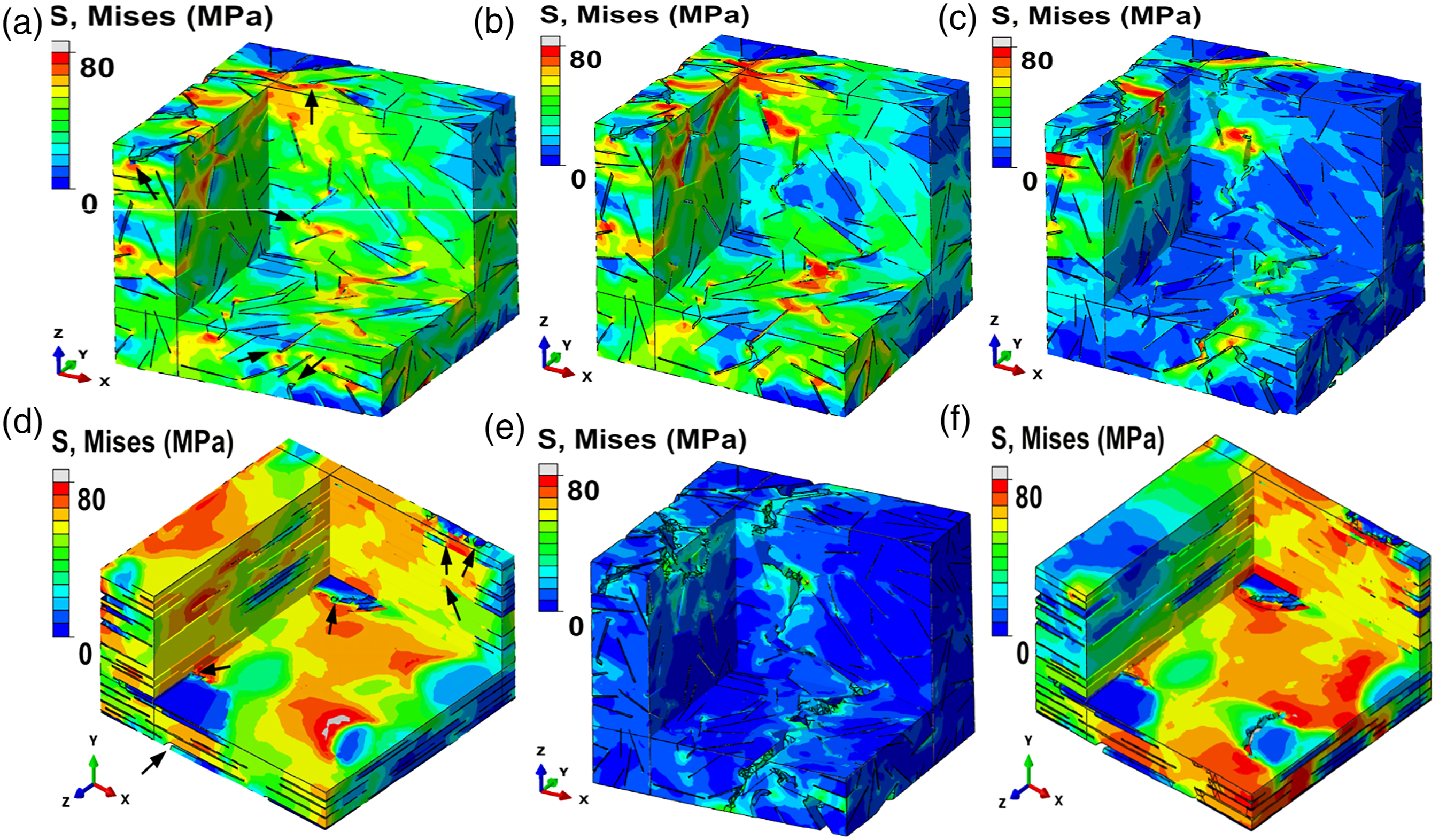
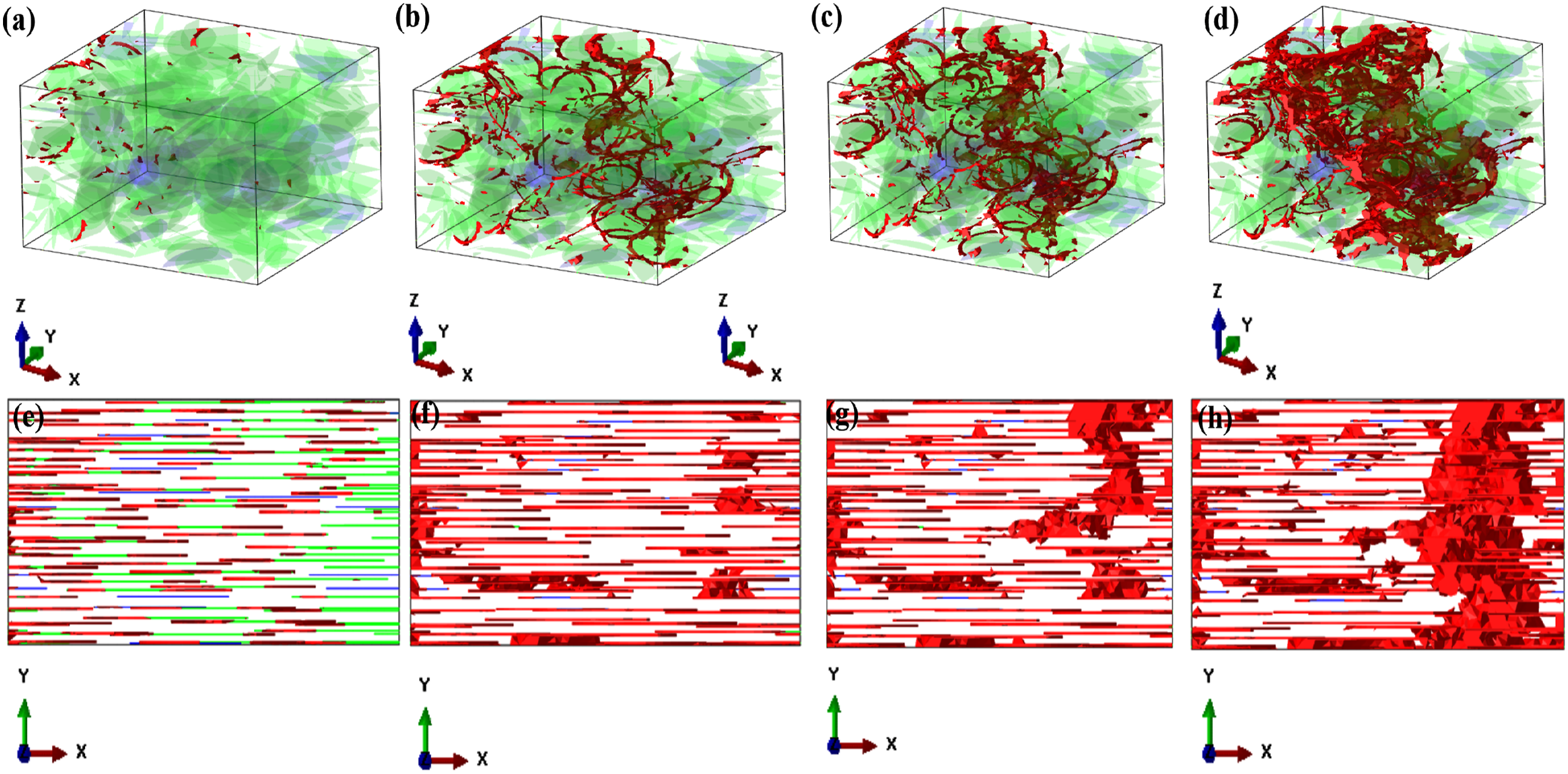
Initially, the M-X@epoxy interfaces begins failure propagation (Figure 20(e)). At the edges, high-stress concentrations of nanofillers were notable (Figures 20(a) and (e)) resulting in creation of localized cracking at the edges of the nanofillers in both RVEs (Figures 20(a) and (e)). For RVE containing randomly positioned inclusions, matrix damaging was seen at a strain value of 0.016 (Figure 20 (a)). With increasing strain, the major crack begins to form (Figures 19(b) and 20(b)) and undergo propagation (Figures 19(c) and 20(c)). A total fracturing of RVE possessing randomly positioned inclusions was seen at a strain of 0.038 (Figure 20 (d)). Contrastingly, for RVE containing aligned inclusions, it was seen at a strain of 0.045 (Figure 19(h)). Post total fracture (Figure 22 (d, h)), the stress minimized, while crack pinning as well as deflection of the epoxy matrix were seen in the fractured RVEs (Figure 20 (d, h)). 142
Finally, this modeling show that both the effective Young’s modulus as well as tensile strength were higher in the composites with arranged M-X and GN inclusions when compared with the composites possessing randomly positioned inclusions. 142
Fabrication strategies of M-X Polymeric Nanoarchitectures
In order to attain optimization of NC properties, sheet-like materials exfoliation as well as complete homogeneous distribution of exfoliated sheets across the polymeric matrix are critically essential. Nevertheless, it is imperative to depict that mechanically inclined reinforcement might not essentially undergo optimization with mono-sheets, as shown for graphene polymeric nanocomposites. 51 Hence, in order to simultaneously attain exfoliation and distribution of M-X nanoparticulates within the polymeric matrix, the mode of nanoparticulates fabrication basically impacts of their architecture and, in turn, properties. Thus, three major NC processing approaches, including, melt mixing, solvent mixing/casting/filtration, and in situ polymerization are prevalent.
Solvent strategy of M-X@polymeric construction
Solvent procedure, entailing M-X inclusion within polymeric matrices through solvent usage, is the most prevalent strategy of fabrication as it is also utilized within the laboratory confinement with direct application of colloidal M-X. Nevertheless, the solvent strategy is usually restricted to protic/aprotic or polar solvents due to inherent M-X compatibility which is prevalently stable within solvents haven a Hildebrand solubility parameter (d) of ∼27 MPa2. 143
Moreover, surface functionalization is capable of sharply improving the stability in zero-polar solvents. 144 Additionally, polymers appropriate for this fabrication strategy are restrained by the solvent utilized. Usually, M-X is added in form of aqueous colloid to a polymeric solution, as the solvent is eliminated through precipitation, vacuum filtration, evaporation, or within a nil-solvent. Numerous M-X nanoarchitectures have been constructed utilizing hydrophilic polymeric substrates, with water as a solvent, including poly (acrylamide) (PAM), polyallylamine hydrochloride, PVA, PEDOT: PSS, PU, cellulose nanofibrils, PDDA, PAA, PEO, polydopamine, chitosan, hyper-branched polyethyleneimine, natural rubber, PI, and polyether-polyamide block copolymer.144–151 Furthermore, solution-oriented processing of M-X nanoparticulates within polar organically inclined solvents have additionally been established for, polysulfone, PVDF-TrFE, epoxy, PVDF-TrFE-CFE, PVDF-CTFE-DB, PVDF, polyacrylonitrile, PPy, PU, and so on.126,127,152–154
Melt processing strategy of fabricating M-X@polymeric nanoarchitectures
During melt processing, M-X embedment within polymeric matrices conducted beyond the polymeric melting point. Melt procedure entails strategies including extrusion, hot pressing, as well as injection molding capable of inculcating arrangement of the M-X nano-sheets. 129 These strategies are specifically enchanting for large-scale M-X nanoparticulates fabrication on refinement or optimization. A significant limitation of melt processability is inherent limitation to polymeric matrices capable of being processed via melting, particularly thermoplastic matrices. Furthermore, high temperatures usage may result in deterioration or M-X nanosheets oxidation. Melt process technique has undergone utilization for fabrication of M-X@polymeric nanocomposites with phthalonitrile, LLDPE, thermoplastic polyurethane (TPU), nylon-6, PS, as well as hyper elevated-molecular-weight polyethylene (UHMWPE).131,132
In situ polymerization (ISP) technique of fabricating M-X@polymeric nanoarchitectures
ISP is an enchanting strategy for fabricating M-X@polymeric nanoarchitectures and involve monomeric polymerization with inclusion of a nanofiller. 132 A remarkable benefit of this strategy is that the polymeric networks are formed close to the nanofiller surfaces. For layered materials, including layered silicates as well as M-X or graphene nanoplatelets, monomeric intercalation, subsequented by polymerization, is capable of resulting to expansion as well as exfoliation of these sheets. 133
Prevalently constructed M-X@polymeric nanoarchitectures fabricated using this strategy include PDMS, epoxies where M-X is inculcated within a portion usually the resin, subsequented by inclusion of the other component, usually the curing agent utilized in initiating the polymerization reaction. Majority of solvents are utilized during this procedure, including or DMF or acetone, in order to facilitate embedment. 134
Summary and Perspectives
Summarily, this review elucidated recent advancement in morphology and its influence on properties and applications of MXene polymeric nanocomposites. Notably, parameters influencing the morphological, architectural and mechanical behaviors of these materials include dimensional stability, interlayer spacing, layered thickness, and porosity, fabrication strategy, type whether carbides or nitrides, constitution whether doping, single-/binary/multi-metallic, defects, and inclusion of nanoparticulates or single atoms, as well as functional entities (O, OH, and F) on improvement of M-X mechanical attributes. These behaviors make the morphological, architectural and mechanical properties of M-X to be similar to varying 2-D nanomaterials including graphene, boronitrene as well as molybdenum disulfide.
In spite of the notable advances attained with the rational designing of pristine M-X and M-X@polymeric nanoarchitectures, their mechanical attributes are theoretically investigated instead of experimentally. Moreover, the fabrication strategies of M-X encompass varying intricate steps, hazardous chemicals, and devoid of exact monitoring, geometry, constitution, and surface/bulk functionalities. Nevertheless, the theoretical calculations forecast the synthesization of varying M-X with remarkable mechanical advantages in addition to electrical conductivity, elevated surface area, as well as ion adsorption/storage attributes, presenting greater opportunities for use of M-X@polymeric nanocomposites in versatile applications including flexible gadgets, energy production/storage gadgets, as well as sensors.
Considering the enchanting electrically, mechanically as well as processability dispensation of M-X@polymeric nanoarchitectures, the synergy of M-X with appropriate polymeric matrices will proffer a wide window for multi-applications. In order to garner greater roadmap for design of materials, in depth comprehension of morphology and interaction between M-X and polymeric matrices are imperative.
Moreover, essentiality of the interfacial interaction, and morphological features between the M-X and polymeric matrices has been versatily investigated, though a lot of work is further required, especially relative to expansive functions of differing surface terminal entities on interaction with polymeric matrices and the morphological arrangement of the M-X@polymeric interfacial architecture, which will positively influence the garnered properties thereby expanding the scope of application of M-X@polymeric nanoarchitectures. Hence, this review can offer a guideline for researchers in designing novel M-X@polymeric nanoarchitectures for versatile multi-functional applications.
Conclusion
M-X and M-X@polymeric nanocomposites are distinctly potential for a vast range of uses and industrial spheres. Despite generation of versatile outstanding results numerous challenges linked with fabrication of these polymeric nanostructures on industrial sphere still persist. The propensity of M-X to oxidation is a major parameter that is critical. Although this segment is still evolving, and the rate of oxidation are slowest within solid media like PVA, oxidation is not totally inhibited by the polymeric matrices. Moreover, the extent to which M-X undergo oxidization in specific polymeric matrices maybe a function of the chemistry and/or architecture of the polymeric material. This challenge should be mitigated as oxidation may prove degradative to the M-X usage as reinforcement in areas wherein M-X oxidation effects performance, especially those requiring conductive M-X sheets, like EMI shielding.
Furthermore, the price tag of MAX phase powders and availability are potential challenges, although novel strategies of fabricating M-X devoid of direct (or indirect) usage of HF is a critical parameter in changing from fundamental investigations to commercially developing M-X@polymeric nanocomposites due to prevalent hazards linked with the storage and handling of huge amounts of HF. In addition, M-X cost of fabrication must be far minimal compared with other elevatedly performing nanoreinforcement, especially CNTs, which even graphene is struggling to outshine on streamlining performance to cost. It is anticipated that with further development of M-X polymeric nanocomposites, and greater quests given to scalable production strategies, enhancements will through more light on strategies of M-X polymeric nanocomposites fabrication most efficient at inducing exfoliation and effecting uniform distribution of M-X nanosheets within enlarged scope of polymeric matrices.
Footnotes
Acknowledgements
Nnamdi Azikiwe University, Awka, Nigeria is acknowledged.
Declaration of conflicting interests
The author(s) declared no potential conflicts of interest with respect to the research, authorship, and/or publication of this article.
Funding
The author(s) received no financial support for the research, authorship, and/or publication of this article.