
Abstract
This study covers a low-velocity impact property analysis of Polyethylene self-reinforced composites (PET-HDPE/HDPE SRC)through experimental and numerical methods emphasizing the influence of interfacial properties. Self-reinforcing a polymer material has gained a lot of attention due to maximum exploration of their light density characteristics with better chemical compatibility and interfacial adhesion of matrix and reinforcement, resulting in higher fuel efficiency. Reusability of self-reinforced thermoplastic composites even without separating their constituent materials has been observed to be aiding the circular economy strategies. The study aimed to analyze the peak load characteristics, energy-absorbing characteristics, and damage response of these materials processed through the hot compaction technique and subjected to a drop mass impact test. Fractographic visual inspection, optical macrographs, Scanning electron microscopy analysis, and through transmission ultrasonic C-scan were employed to study the damage evolution and failure mechanisms under the low-velocity impact. Three levels of impact energy were included in the test matrix, and initiation of the damage, nature of the matrix, interface debonding, matrix and fibre failures could be identified through the inspection of the damage cross-section at the impact eye. A finite element model developed through commercial FEA packages (Abaqus) was utilized for the complex mechanisms of damage and failure. Weak interfacial adhesion due to the self-lubricating nature of the polyethylene fibre surface contributed to the fibre pull out during the drop weight impact. A qualitative analysis and correlation of the nature of surface damage and internal damage were also studied, which are the factors that are necessary for the development of cargo containers and marine/aerospace ultralight luggage applications.
Keywords
Introduction
Polymer composites are one of the major solutions for many structural applications which require better strength/weight ratio and stiffness/weight ratio. When a polymer is reinforced with another denser material, the weight of the component increases. This issue can be overcome if the reinforcing material is from the same family. Such self-reinforced composites are a choice for cargo containers and ultralight luggage in aerospace, automotive, construction, electronics, and a lot of other applications. The use of mild-weight and high-performance substances in aerospace, automotive, marine, construction, electronics, and a lot of other applications has triggered the use of polymer composites, specifically thermoplastic composites. This is due to the high overall performance of polymer composites with minimal weight when compared with conventional metallic substances. Along with environmental implications, the potential to recycle materials is a completely vital aspect of material selection.
Though Polyolefins are lighter than water when they are reinforced with glass, carbon or Kevlar fibre, their density increases. The demand for improved fuel efficiency and reduced environmental impact increases the need for lightweight materials in the automotive, marine and aerospace domains. When the polyolefins are reinforced with a matrix from the same family, density-related issues will be overcome.
Cargo application of these materials demands resistance against low-velocity impact. For instance, hitting a flying object with low velocity or a tool dropped on the material under maintenance causes damage. Foreign body impacts on composite structures can cause interior damage, weakening the structure’s strength dramatically. Some important features of impact failure on laminated composites were presented by Serge Abrate in 1991 and 1994 based on detailed literature reviews.1,2 S Ramanathan and Kishore analyzed drop mass impact properties of glass-epoxy composites and studied post-impact inter-laminar shear stress. 3 Effects of single and multiple impacts with impactor shapes on thermoplastic and thermosetting polymer composites subjected to low-velocity impact were studied by the researchers. 4 E Glass fibre reinforced polypropylene composites were found to possess a higher perforation threshold than the composite fabricated by reinforcing the same fibre in the epoxy matrix. Conical impactors needed significantly less number of impacts for perforation (3 events) compared to hemispherical impactors (36 events). The influence of hybridization and low-velocity impact properties of glass-graphite/epoxy hybrid composite beams revealed a high load-carrying capacity under impact loading. 5
When hybrid composites of commingled yarn fabrics of glass fibres are reinforced in various thermoplastic matrices like PE, PP, PA and PET and thermosetting matrices like epoxy, the hybrid composites had better impact resistance compared to non-hybrid composites. 6 When glass fibre is reinforced in thermoplastic Polypropylene matrix with an enhanced interface with compatibilizer maleic anhydride, non-compatibilized samples outperformed compatibilized samples under low-velocity impact. While quasi-static test results yielded a reverse trend. 7 It was observed that woven composites possess better impact resistance compared to unidirectional composites for various grades of glass fibre and aramid reinforced composites. It was also identified that the strain sensitivity increases the impact strength in such composites. 8 Thus, it was decided to select woven fabric for the study.
Self-reinforced polyolefin composites are fully recyclable and thus cause less environmental impact. The single-polymer composites concept was firstdescribedin1975 by Capiatiand Porter in which polyethylene (PE) powder and oriented polyethylene (PE) filaments with different melting points were used. 9 Low-velocity impact properties of all Polypropylene (PP) composites made from PURE® tapes (commercially available PP SRC) fabricated by stacking PURE® tapes through hot pressing. 10 It was reported that there was no perforation observed and the average energy absorbed was 300 J due to the higher thickness of the specimens. Another recent study indicates that 3D angle interlocked fabrics of Kevlar and Basalt reinforced in PP provide an energy absorbing capacity of 58 J and 104 J, respectively, and a hybrid of these two fabrics reinforced in PP exhibits an energy-absorbing capacity of 112.93 J. 11
For the creation of a numerical model that could accurately characterize the impact and predict the complicated interior damage mechanisms in a relatively short time, the finite element (FE) technique was considered. Understanding the dynamics of such impacts is vital for determining the extent of the inflicted damage and evaluating the structure’s remaining strength. 12 An overview and introduction to composite material damage theories, as well as a FE impact model for forecasting impact reaction and damage, were studied by the researchers with In-plane cohesive properties used to capture ply splitting, and the model is found to be in good agreement with the experiments. 13
FE models for capturing the impact response and damage of laminated composites have been presented by the researchers in the previous literature. 14 Modelling of impact damage and permanent indentation due to low-velocity impact was simulated with three damage types: matrix cracking, fibre failure and delamination. In another study, a ‘plastic-like’ model was developed and used to simulate the physics behind some type of indentation after the impact. 15
A unique, ply-level, computationally efficient three-dimensional (3D) composite damage model was developed in the past and used to predict the impact response of unidirectional (UD) PMC laminates at low velocity. The proposed model was implemented in the Finite Element (FE) code ABAQUS/Explicit for one-integration point solid elements. 16 A new decohesion element has proved to be capable of dealing with crack propagation under mixed-mode loading. The element was used to describe the initiation and evolution of delaminations in composite materials at the interface of solid finite elements. 17 The effect of composite structure size and complexity on the production of low-velocity impact damage was investigated to obtain a high level of realism locally under the impact area, and the researchers employed a novel numerical technique that blends 3D solid and thin 2D shell parts. 18 The in-plane and out-of-plane elastic characteristics of quasi-isotropic materials were expressed using closed-form formulas, and the equations are useful for estimating the overall effect of specific material selections in simplified engineering calculations. 19 The interacting failure criteria with many stress components were employed to assess the various failure modes for unidirectional polymeric composites, and they have considerable approximations when applied to other types of laminates and non-polymeric composites. 20
The structural behaviour of the structural sub-floor component made of a carbon fibre-reinforced composite material under dynamic loading conditions were examined by the researchers. The impact behaviour of the entire subfloor component was then numerically modelled, with the initiation and propagation of inter-laminar and intra-laminar damages. Numerical impact studies were performed to completely explain the damage process in order to build a crash-worthy aircraft floor. 21 The developed model’s capacity to predict the impact behaviour of the investigated honeycomb core was good and further proved by the excellent agreement between the computed deformed forms and the observed deformations at various phases of the experimental impact test. 22 A novel technique has been created that, unlike typical Paris-law-based processes, can estimate the rate of delamination increase over fatigue cycles. It may be utilized to properly describe the behaviour of geometrically complicated structures when inter-lamina damage progression is expected. 23 Ultra High Molecular Weight (UHMWPE) composites possess promising ballistic impact properties. Researchers have developed a combined theoretical-semiempirical penetration model of ballistic penetration of thick section composites and new penetration equation for ballistic limit analysis which predict projectile residual velocity at and around ballistic limit has been developed.24,25 It has been observed that soft body armor pack (SBAP) fabricated from high performance UHMWPE soft ballistic sub-laminates (SBSL) can defeat handgun projectiles. 26 A simple penetration model has also been developed to analyze the depth of penetration (DoP) of Dyneema® HB26 hard ballistic laminates. 27
Polyester and polyolefin materials are the most studied thermoplastic materials, and the most frequently used manufacturing technique is film stacking with hot compaction, in which matrix film generally has a lower melting point than the fibres so that only the matrix films melt under thermal processing. They also possess commendable interfacial properties between the matrix and the reinforcement, which is expected to improve their toughness as well. In this context, the low-velocity impact response of hot compacted PE/PE-PET copolymer self-reinforced composites was analyzed. Energy absorption, peak load carrying capacity, velocity and deflection profiles, and analysis of damage nature at macroscopic and microscopic levels, the influence of interfacial properties through experimental and computational techniques are the major focus of this study.
Computational
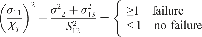
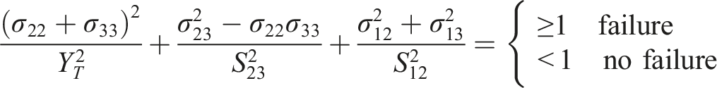
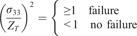
Hashin criteria are often applied to point stress calculations using a two-dimensional classical lamination technique with ply discounting as the material degradation model. Hashin criterion failure indices are based on fibre and matrix failures and include four failure categories. 1. Tensile fibre failure for σ11 ≥ 0 2. Compressive fibre failure for σ11 < 0 3. Tensile matrix failure for σ22 + σ33 > 0 4. Compressive matrix failure for σ22 + σ33 < 0 5. Interlaminar tensile failure for σ33 > 0 6. Interlaminar compression failure for σ33 < 0


Modelling of composite laminate
The composite is modelled by a number of distinct layers, each with orthotropic material properties using the mixed modelling technique. The material properties implemented in composites through the layers are usually regarded to be elastic. The mixed modelling technique is used in the analysis with layered continua three-dimensional hexahedral elements with displacement degrees of freedom. Its usage generally is confined to cases where bending effects (hence, delamination caused by shearing) is not significant in any direction. For modelling each lamina independently, the model uses eight noded plane stress continuum shell elements with reduced integration (SC8R element in ABAQUS). The benefit of having nodes on the top and bottom surfaces of the ply is provided by continuum shells. This eliminates the need to account for rotational degrees of freedom in the cohesive element formulation when capturing the traction separation relation of adjacent surfaces. Hourglass control is applied to compensate for the reduced integration.
Shell elements are used to model structures in which one dimension, the thickness, is significantly smaller than the other dimensions. Conventional shell elements use this condition to discretize a body by defining the geometry at a reference surface. In this case, the thickness is determined through the section property definition. Conventional shell elements have displacement and rotational degrees of freedom. In contrast, continuum shell elements discretize an entire three-dimensional body. The thickness is determined by the element nodal geometry. Continuum shell elements have only displacement degrees of freedom. From a modelling point of view, continuum shell elements look like three-dimensional continuum solids, but their kinematic and constitutive behaviour is similar to conventional shell elements.
Modeling with continuum shell elements
The element geometries for the SC6R and SC8R elements are a triangular prism and hexahedron, respectively, with displacement degrees of freedom only. Continuum shell elements must be oriented correctly since these elements have a thickness direction associated with them. When classical shell structures (structures in which only the Midsurface geometry and kinematic constraints are provided) are analyzed, care must be taken that appropriate moments and rotations are specified. For example, a moment may be applied as a force-couple system at the corresponding nodes on the top and bottom faces. A rotation boundary condition may be specified through a kinematic constraint to yield the appropriate displacement boundary conditions on the edge of the continuum shell.
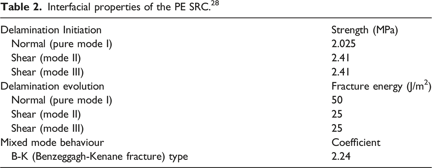
The laminated PE SRC plate is modelled with three-dimensional individual layers, each of thickness of 1.2 mm, bonded together through the surface area using cohesive behaviour. To reduce computing costs, the model employs a “global-local” modelling technique. From here out, the “local” region is referred to as the “impact area.” The cohesive behaviour contact algorithm connects the layers in the impact area as well as the global area. The mesh is coarse away from the impact area and fine in the impact area. A mesh refinement research is carried out in the impact zone with element sizes of 0.8 mm, 1.0 mm, 2 mm, and 2.5 mm with a global mesh size of 3 mm. The figure shows the impact force-time curves. The accuracy of the model in predicting the maximum force increases as the element size decreases. So the mesh should be small enough to completely capture the dynamic progressive deterioration of a composite laminate without being too computationally expensive and should have a balance between computational economy and accurate prediction. As a result, in the impact zone, the finer mesh with 1 mm element size is utilized, whilst the coarser mesh of size 3 mm is used in the zone away from the impact area (Figure 1). Mesh convergence data.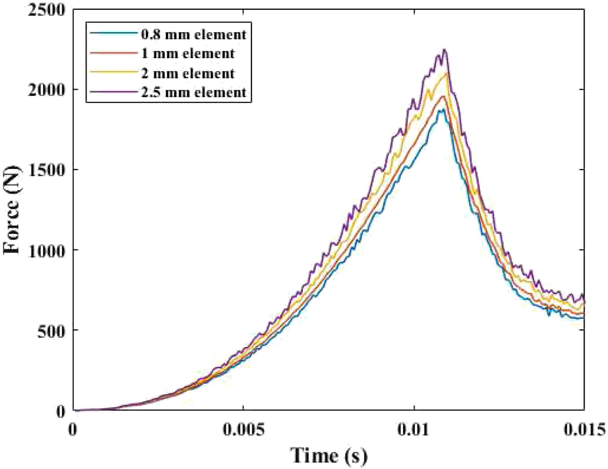
The results shown are for a mesh size of 1 mm by 1 mm in the impact area and 3 mm by 3 mm in the rest of the area. The impact area was determined to be large enough to accurately capture the observed damage footprint for different lay-ups. The number of elements in a layer is 7696, and thus, for three layers, the total number of elements used is 23,088. The diameter of the tup modelled is 20 mm with a mass of 5.5 kg assembled to impact the plate upon which the kinetic energy from the tup is transferred to the plate. The impactor is modelled with 251 rigid body elements with a reference point to provide mass property and density.
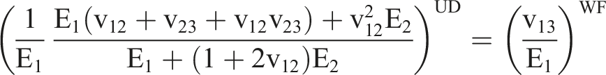
Properties of PE SRC laminate.
The explicit analysis was used to solve with nonlinear dynamics and contact algorithm applied to surfaces. The analysis step was created with a total step time of 15 milliseconds based on the experimental time taken. To determine the stress and damage fields, field output variables were acquired at 200 evenly spaced intervals.
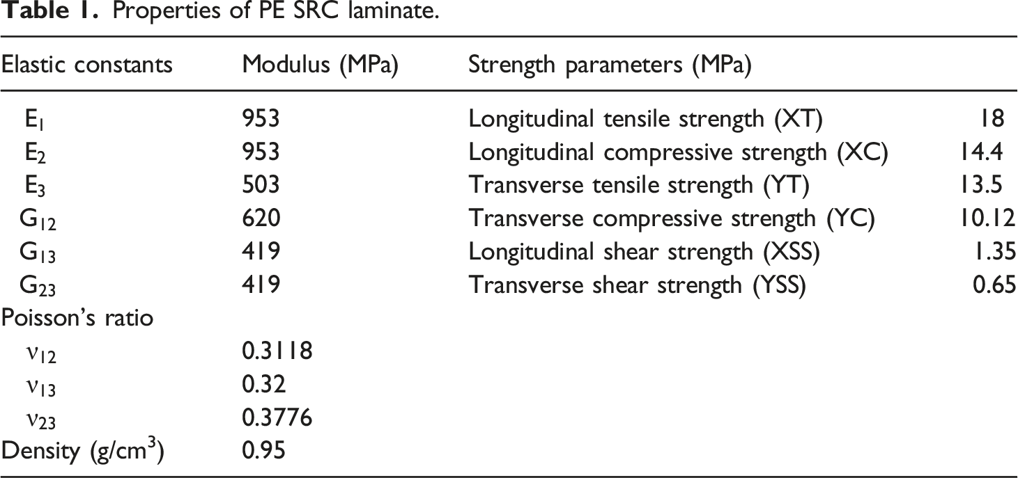
The material properties used in Abaqus are calculated using formulas given below based on Akkerman.
The simplest approximation is a set of elastic properties 

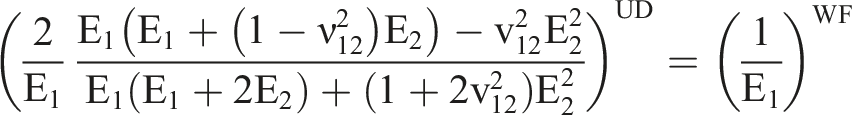
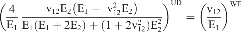
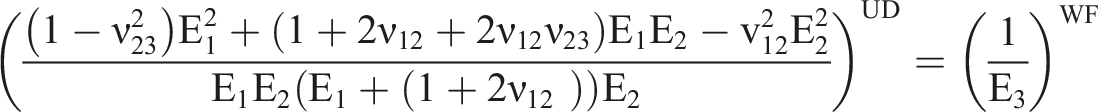
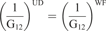
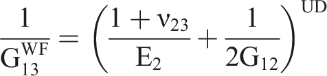
Thus the available unidirectional properties can be converted to equivalent bidirectional properties for a woven fabric. The values obtained are tabulated as follows
Experimental
Materials and Fabrication
Polyethylene Self Reinforced composite (PE SRC) (HDPE matrix/PE-PET)copolymer fabric laminates for drop mass impact test were manufactured from plain weave 120 GSM fabrics and 1 mm thick sheets of PE by hand lay-up method followed by hot compaction (Figure 2) based on the data obtained from Differential scanning calorimetry and Thermogravimetric analysis.
29
A difference in the melting point of matrix and reinforcement is the key factor in heat treatment and fabrication. Materials with a higher melting point is selected as reinforcement (PE-PET copolymer), and lower melting point (HDPE sheet) are selected as a matrix. Matrix melts, and the reinforcement will be intact since the temperature is raised to reach the melting temperature of matrix material under the hot compaction process. A matrix volume fraction of 73.7% was maintained for all PE laminates. Three layers of matrix sheet and fabric, as shown in Figure 2(a), are kept over a mild steel plate of around 12 kg weight covered with mold release spray-applied nylon ply. The stacking is then closed with another mild steel plat of the same weight and cover. The assembly is then tightened with C-clamps to impose pressure. Heat treatment was performed for the assembly in an industrial oven, and the temperature was allowed to rise just above the softening temperature and then maintained at the same temperature for another 1 h. A temperature of 115°C was maintained at the centre of the laminates. Then the oven is switched off, and the samples are allowed to cool gradually to room temperature for 24 h. After attaining the room temperature, the clamps were removed, and 3 mm thick, 500 mm × 500 mm laminates were cut into nine samples of PESRCs based on the required dimensions (150 mm × 100 mm). Fabrication of composite laminates by hot compaction (a) stacking sequence of laminate (b) fabrication sequence.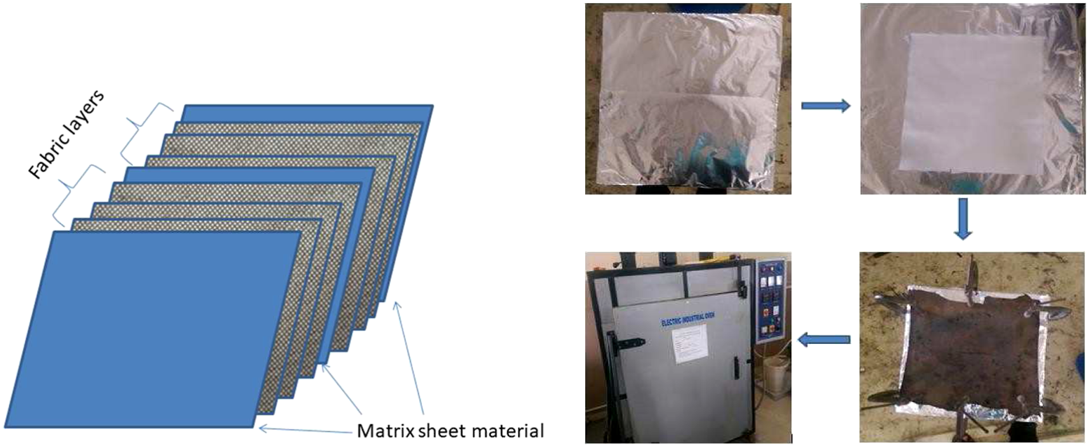
Detailed static mechanical characterization is performed on these laminates by the authors with ASTM standards in a previous study (Table 1) Three-point bending under static loading is another important parameter to correlate as the proposed study for this paper considers flexural loading on the plate. Authors have reported the flexural properties of these laminates in the previously mentioned work conducted on the same type of samples fabricated through the same procedure and processing conditions. 30
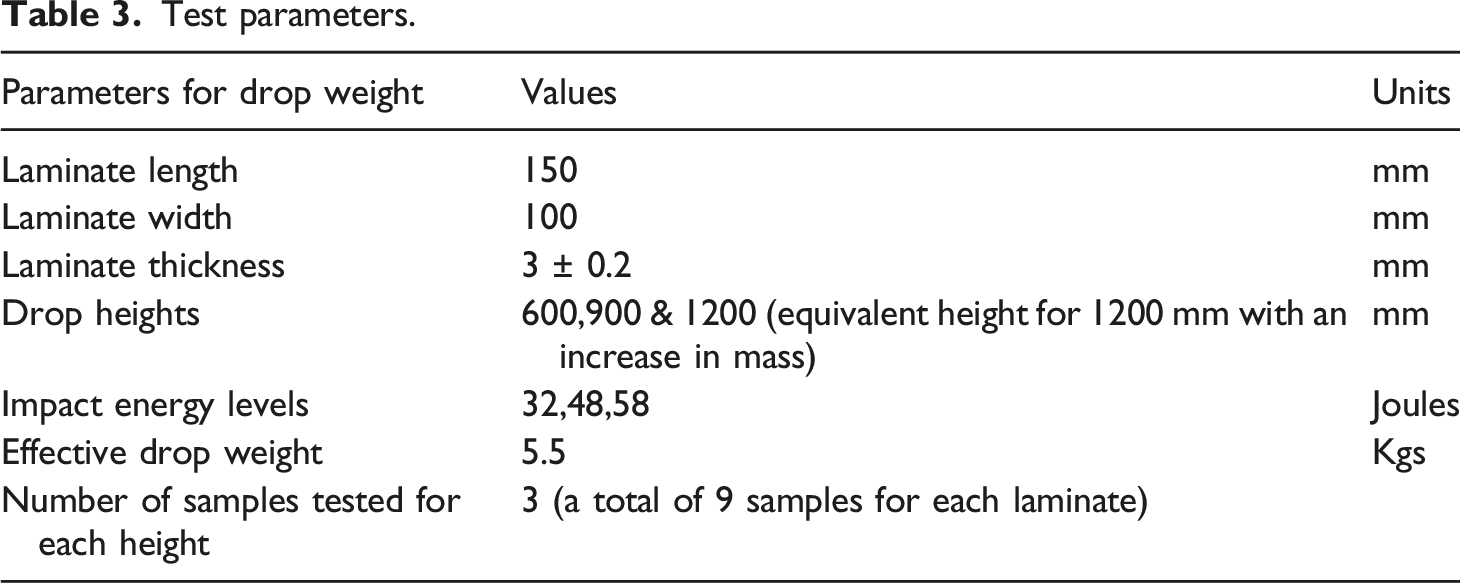
Impact tests of laminates
Test parameters.
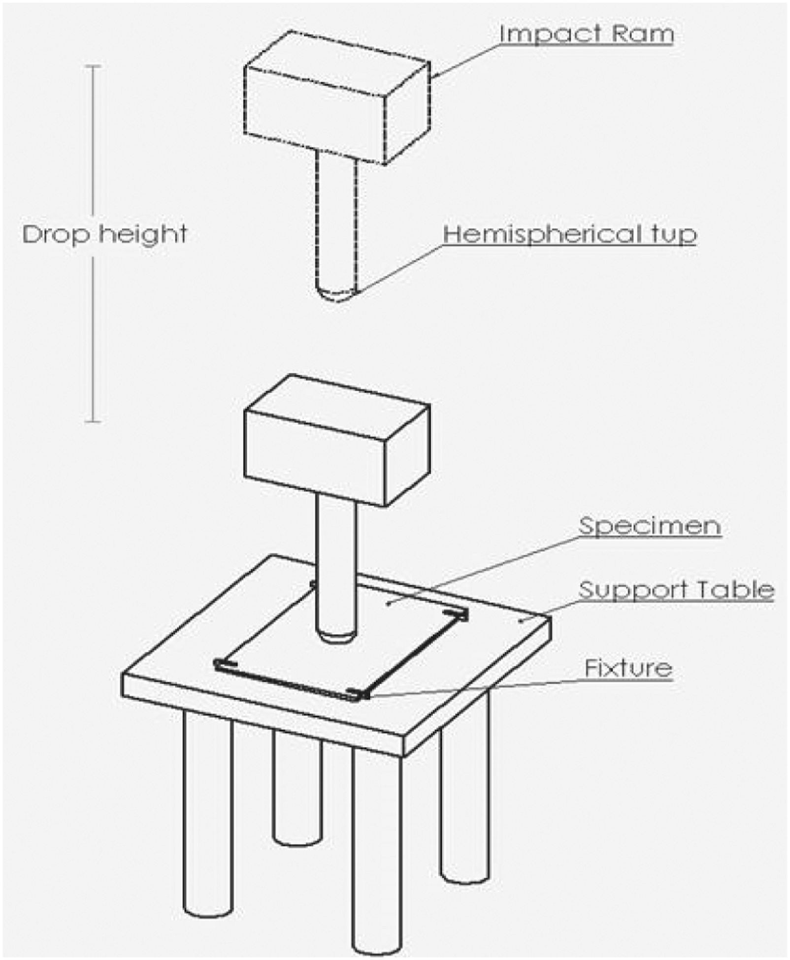
Schematic diagram.
Ultrasonic C-scan
Through transmission, testing was used to evaluate extent of damage in the sample. Samples were immersed in water, to act as an effective coupling fluid in the Inspection. After inspection, the samples were dried clean to avoid hygrothermal degradation and two separate probes were used for transmitting and receiving the ultrasonic energy. The probes are placed on the opposite side of the sample at an equal distance. The signal from the good region is taken as a reference, and gain is adjusted in such a way that the signal will not get saturated. In the damaged regions, the sound waves get scattered or returned, and sound energy reaching the receiver transducer will be less than in good regions. This technique shows an abnormality in material but not the depth of the abnormality.
Ultrasonic Parameters • Transducer Frequency = 2.25 MHz • Transducer focal distance in water = 2” • Pulser voltage = 200 V; • Gain Levels: (Sample PE = 1.2 dB; Sample PP = 7.6 dB; Sample U = 35 dB) (The gain levels are adjusted in such a way that the signal will not get saturated while scanning).
Scan Parameters • Scan Axis = 0.1 mm; • Index Axis = 0.5 mm
Results and discussion
Computational simulation
Figure 4(a)–(d) represent the response of the material under the drop weight simulation. The elasticity of the plate during the initial contact between the impactor and the composite laminate at first is indicated by a smooth curve till the peak. Near the peak force in the load versus time curve of PE model, some oscillations begin to occur, indicating that damage has been initiated. After the peak load, the force decreases with some more oscillations in PE due to increased energy involved attributed to delamination and fibre damage. The impactor is penetrating the plate at all energy levels. Hence damage pattern and load versus time and energy versus time graph are similar in a material at a different energy level, and each model is differentiated using three impact velocities. Since initially, impact at three energy levels was proposed and experimented in order to quantify the damage at each level, and the simulation is also performed for all three models. The graph corresponding to each velocity shows a similar pattern, whereas the peak load and deflection is increasing with an increase in energy, indicating the penetration and severe damage. Hence the best interest is to compare both materials in terms of overall damage characteristics as well as each model’s progressive failure. The higher the impact energy higher is the damage due to impact. The non-linearity of the curve at the end indicates elastoplastic irreversible damage. The plate, until reaching peak load, exhibits elastic deformation. (a) Load versus Displacement plot (b). Energy dissipated due to damage (c). Kinetic energy versus Time plot (d). Load versus Time plot (e). Cross sectional view of Impactor and plate (f). Matrix Tensile crack initiation (g). Hashin Matrix tensile failure criterion.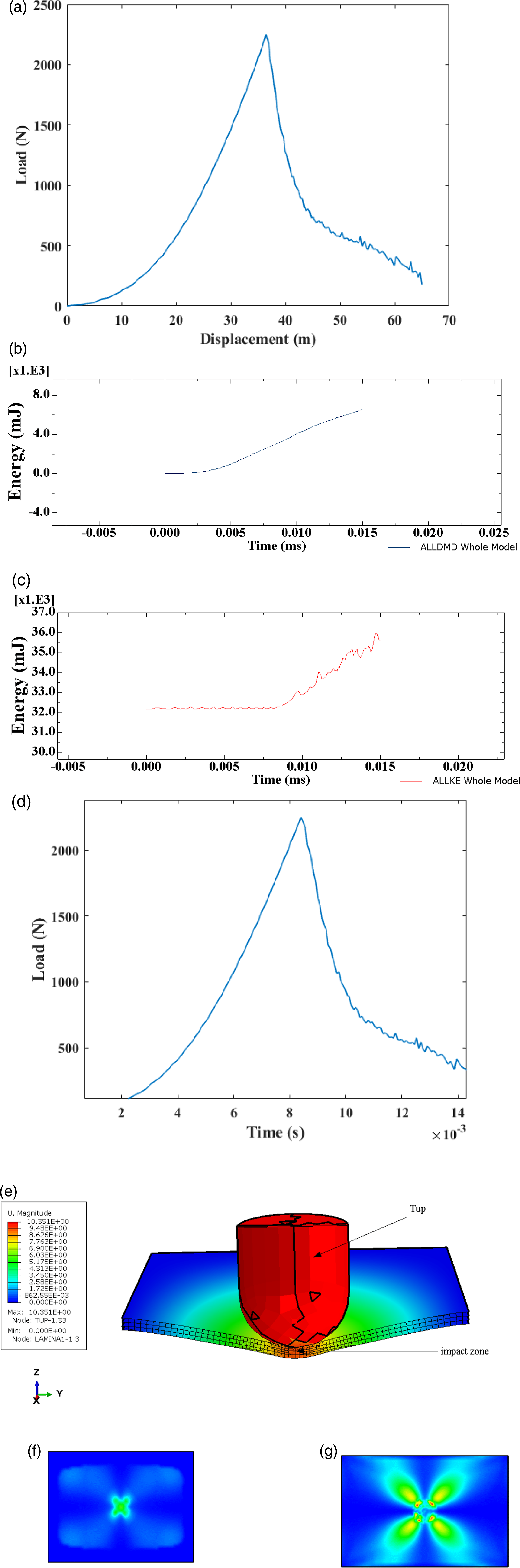
After the peak, decreases in force accompanied by absorption of the energy by the plate due to damage. There is a slight increase in energy during initial contact, which adds to the elasticity of the plate there, some energy is spent on damaging of the sample. The remaining energy is plotted as absorbed energy. Since the dissipated energy is less, it indicates the sample not withstanding prolonged elastic deformation but undergoes an elastoplastic deformation also detected experimentally, and the larger force reduction seen at approximately 11 ms can be attributed to fibre breakage. The numerical result indicates a slightly lesser load value than the experimental result, and load reduction is quicker than the rise shows the beginning of penetration. For higher energy, the penetration pattern is similar. However, there is deep penetration with large deformation, and damage is also severe with a higher damage area. The numerical model produced a good agreement with experimental results with slight under-prediction of impact force and with slight over-prediction of the damage area.
The failure of the laminate is calculated based on the hashing criteria. Figure 4(e) is the cross-sectional view of impactor and plate. Figure 4(f) and (g) shows damage patterns at different points of time through the time history of the impact event, which can be controlled by requesting the output at as many intervals as needed. Also, the model is able to provide damage patterns for different energies even at various required intervals of time. Thus the numerical model is efficient and able to predict the impact damage.
The Figure 5 shows progression of stress through various time histories of impact events beginning with initial contact of the tup to the final loss of complete energy by the tup. The maximum principal stress distribution and the area of maximum yield happen at a later stage but the visualization at various stages helps in understanding the progress of stress. However, the geometry of the specimen plays a role in stress distribution, which reaches the edges more quickly in the transverse direction than in the longitudinal direction. However, the maximum yield is confined in the area exactly under the tup, which undergoes maximum compression due to impact. Max Principal stress.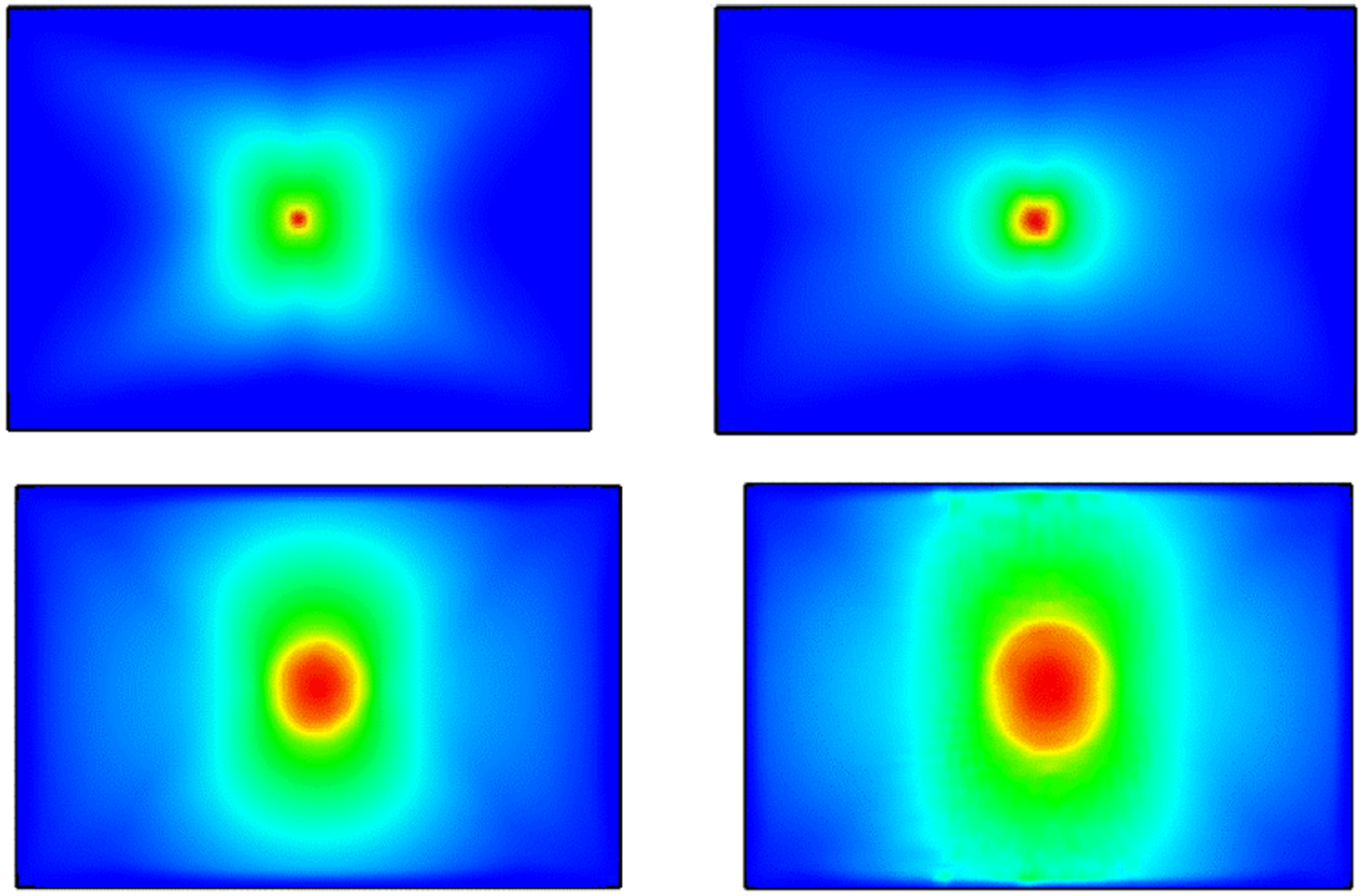
In Figure 6 the red zone in the middle indicates the maximum deflection area which is much smaller than the elastic deformation zone indicated in green colour. Initial Deflection from simulation.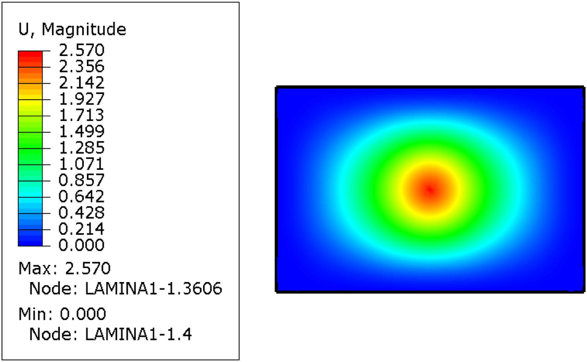
Figure 7(a) and (b) shows a cross-sectional view of the model with a deflection at various time history that can be used to infer damage modes and characteristics of the impact. The elements in the green zone undergo deformation, and the mesh pattern is intact almost, which is useful in deducing that zone as undergoing elastic deformation with plasticity at the small yellow ring-like zone. From the figures, there is yield around the centre impact zone which begins early in the system before the beginning of deformation in the green zone. Also, in the impact zone, there is a severe crash. Therefore the yellow area connecting the elastic deformation zone and severely crushed impact area indicates plastic deformation and debonding, which is irrecoverable damage. The blue zone indicates an intact part. Figure 7(c) shows delamination through the layers and Figure 7(d) shows the top view of the delaminated area in the middle layer obtained by hiding the first lamina. The delamination is obtained by using the damage variable CSDMG, which relates traction and separation between the interfaces. The interfacial property between layers is governed by cohesive behaviour which is applied between the layers using layer-to-layer interaction. (a). Deflection at middle stage (simulation), (b). Deflection at the final stage, (c) Delamination through layers, (d). Delaminated zones.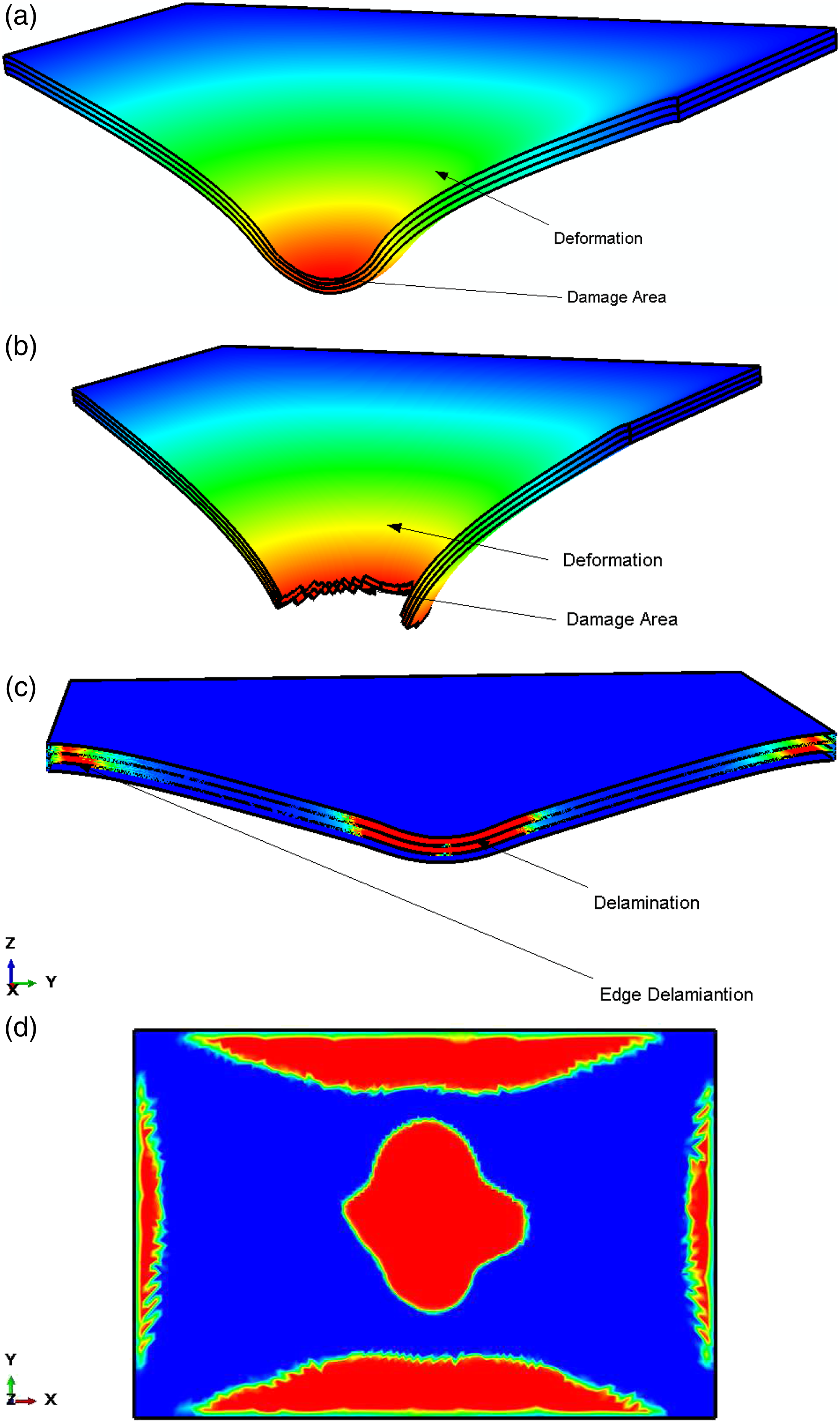
Experimental
Maximum, average and minimum values of maximum load, absorbed energy and damaged area for PE and PP SRC laminates.
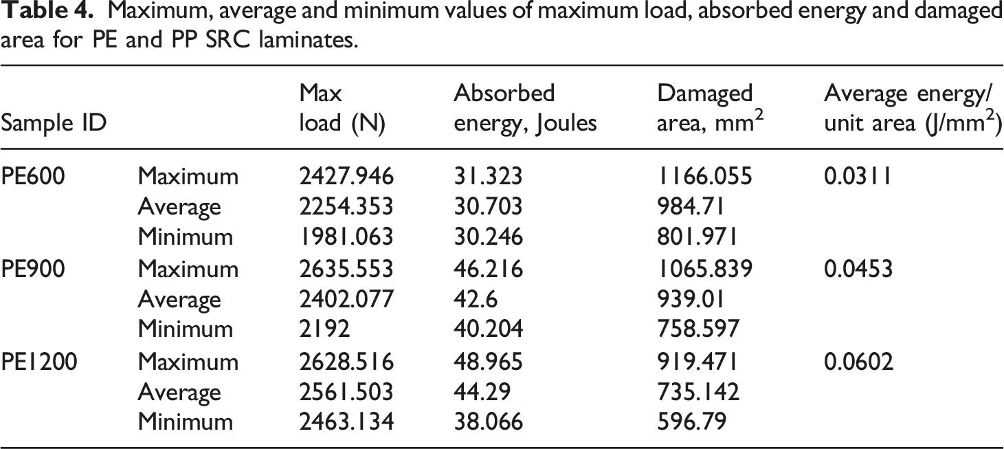
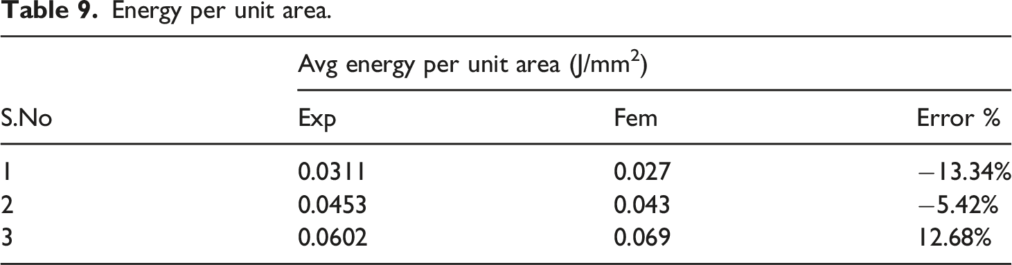
From the data presented in Table 4, it is evident that though the damaged area is not uniform, energy absorbed per unit area gives an insight into the toughness properties of the material. It can be observed that the PESRC is showing a slight increment in the average energy absorbed per unit area when the impact energy level is increased. At the lowest impact energy level, damage of PESRC was just initiated, and it had got higher energy absorbing capacity per unit area. When the impact energy approaches the critical energy absorbing capacity of the PESRC, the average energy absorbed per unit area approaches a constant value.
Different damage patterns are observed during the entire process, and based on the previous studies
9
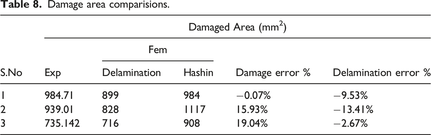
; damages are classified into three general categories. (1) Perforation or complete passage of the impactor through the specimen, (2) penetration or partial perforation and (3) rebound. The first two categories were observed in the materials considered in this study, and various characteristic plots were analyzed from that perspective. Impact energy is utilized for initial material damage (matrix cracking, fibre fracture, delamination etc.), heat generation and progressive damage of the laminate. Microscopic analysis reveals various types of damages that occurred in this study. Figure 8 shows an example of how a measurement of the damaged area is carried out in a PE SRC. Damaged area in one of the samples.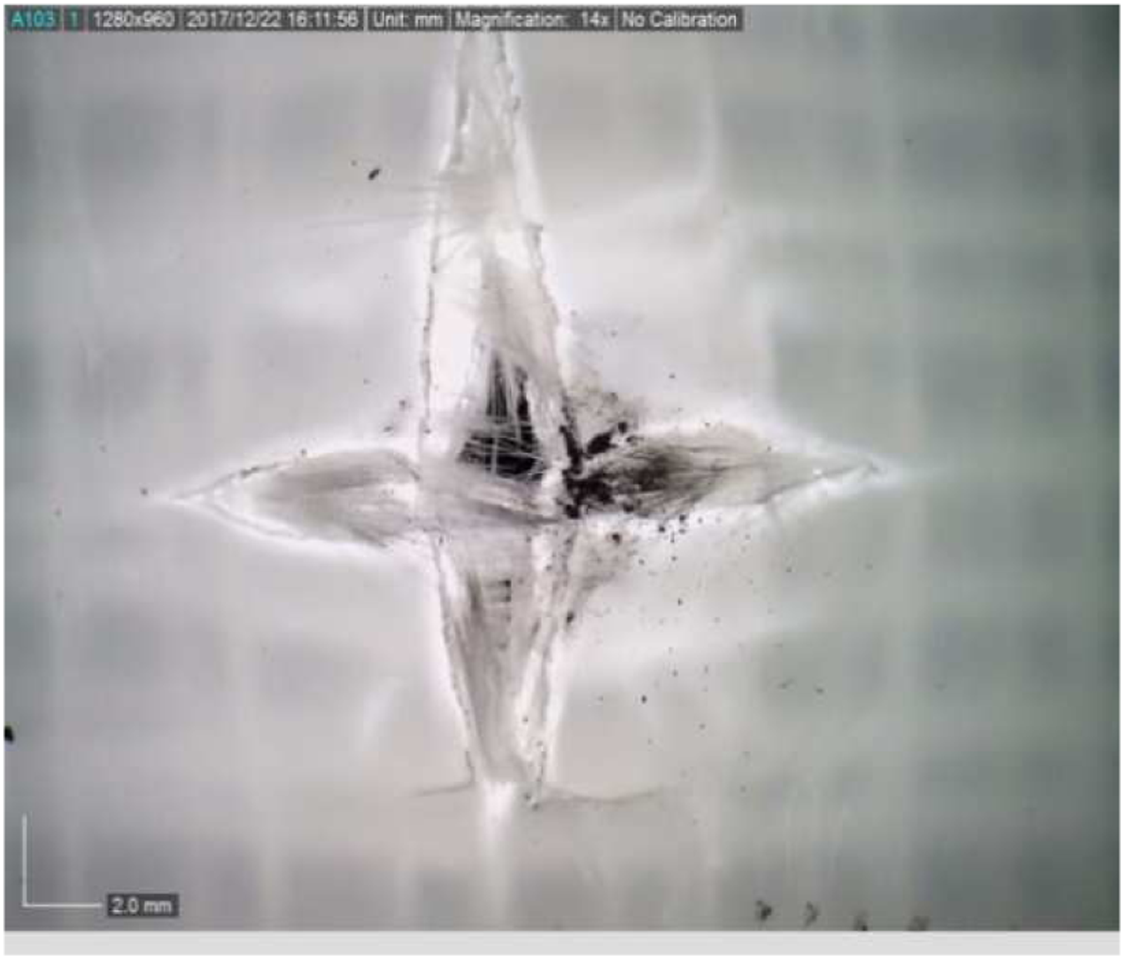
Peak Load characteristics
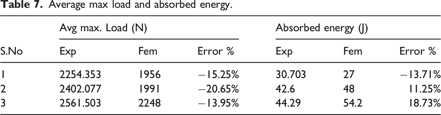
The load exerted by the impactor on the samples are recorded by using a piezoelectric load cell. PE/PE-PET SRC has a commendable load-carrying capacity under low-velocity dynamic loading conditions (Figure 9). Load carrying capacity has been improved under dynamic loading compared to static loading, as it is expected. It was also noticed that all the PE SRC samples tested under three different energy levels (32 J or 600 mm height, 48 J or 900 mm height, 58 J or 1200 mm height)had shown gradual increment. Load-time Plot PE.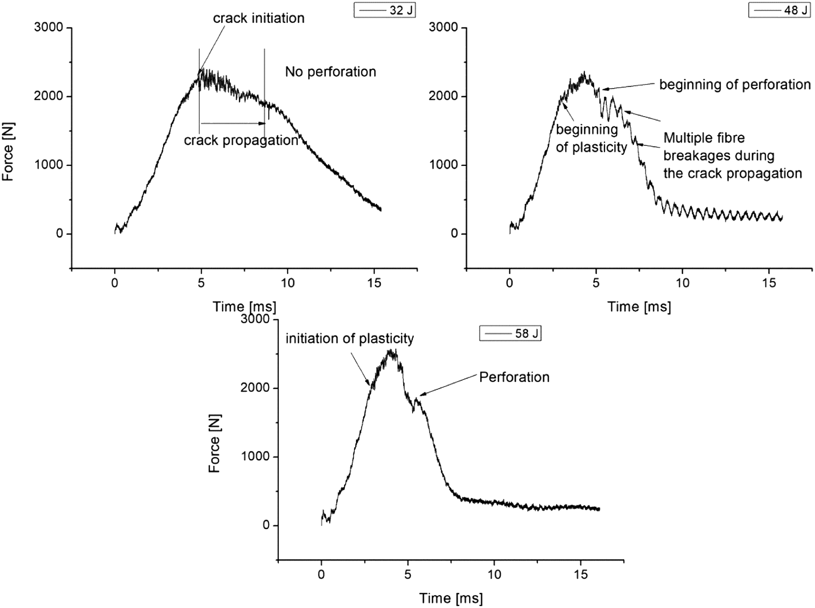
Load time plots of PE SRCs have been shown in Figure 8. The load-time plot shows some oscillations and takes more time to drop from the maximum load at the lowest energy of impact. When the energy level of impact increases, a sudden drop in load occurs right after the maximum load very early for PE SRCs (Figure 9). A few samples of PE SRC under low energy levels indicate returning to zero force which indicates penetration. PE SRC takes more time to deform under low energy levels and bounds a larger area under the force-time graph. Frictional losses are also less at lower impact energy. Higher oscillation in load indicates heavy vibration effects in all these tests due to less strength of these materials under dynamic loading.
The first major drop in load history occurs at the critical load at which the first failure occurs, and that will be the location from which the further delamination progresses due to a reduction in laminate stiffness. The load drops to a point called a residual load, and further, the load rises again if the impactor possesses enough energy. This trend continues up to the maximum load.
Load deflection graph (Figure 10) passes through an ascending zone reaching a maximum and descending after that. A region of a sudden drop in the force is visible in the force-time plot, which is an indication of Hertzian failure (H) or initial damage.
9
As told in the literature, it is noticed that H is a material characteristic depending on the material and thickness of the material. The slope of the initial ascending part of the curve is an indication of the bending stiffness of the material under impact loading. The slope is not remaining constant in the load history and changes after the initial damage. Representative Load-displacement Plots for laminates tested from different heights (a) 600 mm height (b) 900 mm height (c) 1200 mm height.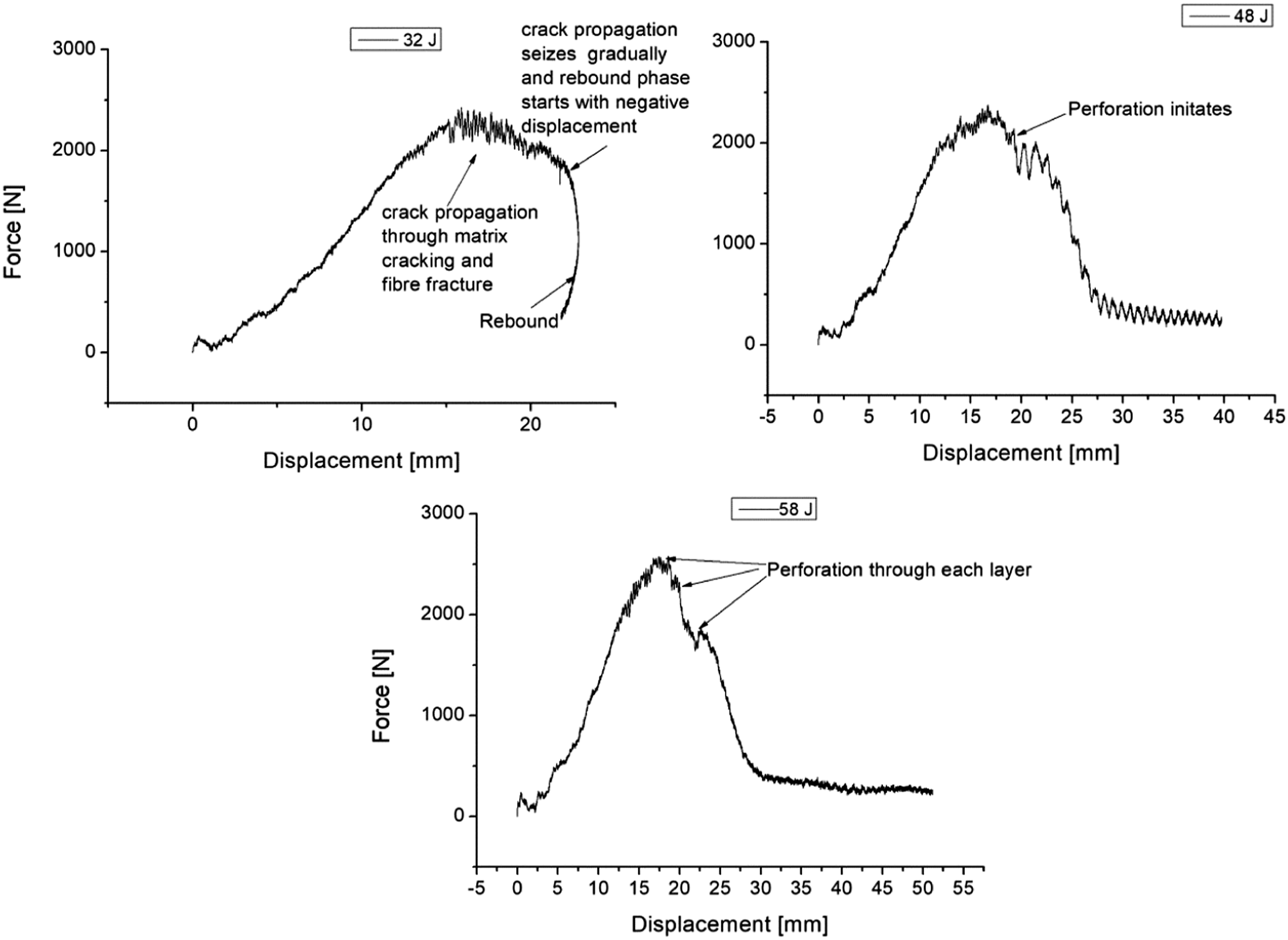
The load-displacement diagram interprets the response of the material under dynamic load. The three events of impact testing can be explained from load-displacement data. A closed curve represents rebounding, while open curves indicate penetration and perforation.
If the specimen experiences deflection with rebounding, the curve will trace back to its origin. Penetration causes an open-end load-deflection curve with a negative slope, and perforated samples show plots of a continuous constant force-deflection curve dropping after reaching the maximum load and attaining a constant force progression. Most of the PE SRC samples experienced rebounding (with penetration and partial plastic damage) for experiments conducted at 32 J and 48 J energy levels. This can be clearly observed from the load-deflection plot. An open-ended and negative slope in a load-deflection plot is an indication of partial perforation or penetration. Under a high energy level of 58 J, the material experiences perforation, which can also be observed from the plot.
Energy absorbed by the material can be obtained by calculating the area under the load-deflection diagram, excluding the frictional effects. The minimum threshold energy required to deform PE SRC is around 30 J. As the impact energy increases from 32 J to 48 J, the area bounded by the load-deflection plot also increases. When the impact energy reaches near the maximum absorption capacity of the material, the area under the curve will remain almost the same.
Energy profiles and comparisons
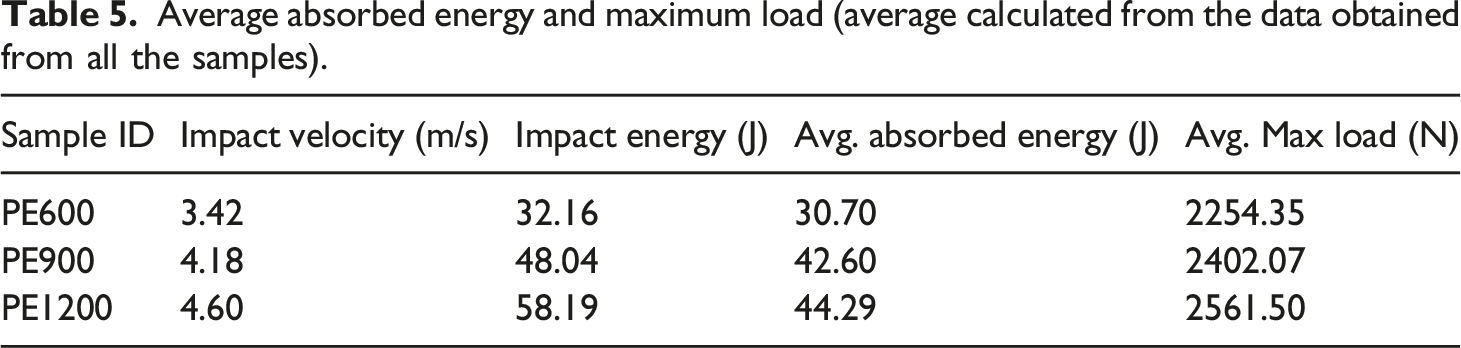
Average absorbed energy and maximum load (average calculated from the data obtained from all the samples).
The energy profile method (EPM) is described through a diagram that compares the impact energy and the absorbed energy (Figure 11). An equal energy line is also traced in the EPM in order to compare the impact energy and absorbed energy. Impact energy and absorbed energy are almost equal for PE SRC at 32 J, which indicates the onset of penetration. If the energy is not sufficient to cause perforation, resistance from the specimen causes the impactor to rebound. For rebounding, the data points will be close to the equal energy line, and as the energy increases from the threshold energy for perforation, the data points move away from the line. Energy profile diagram.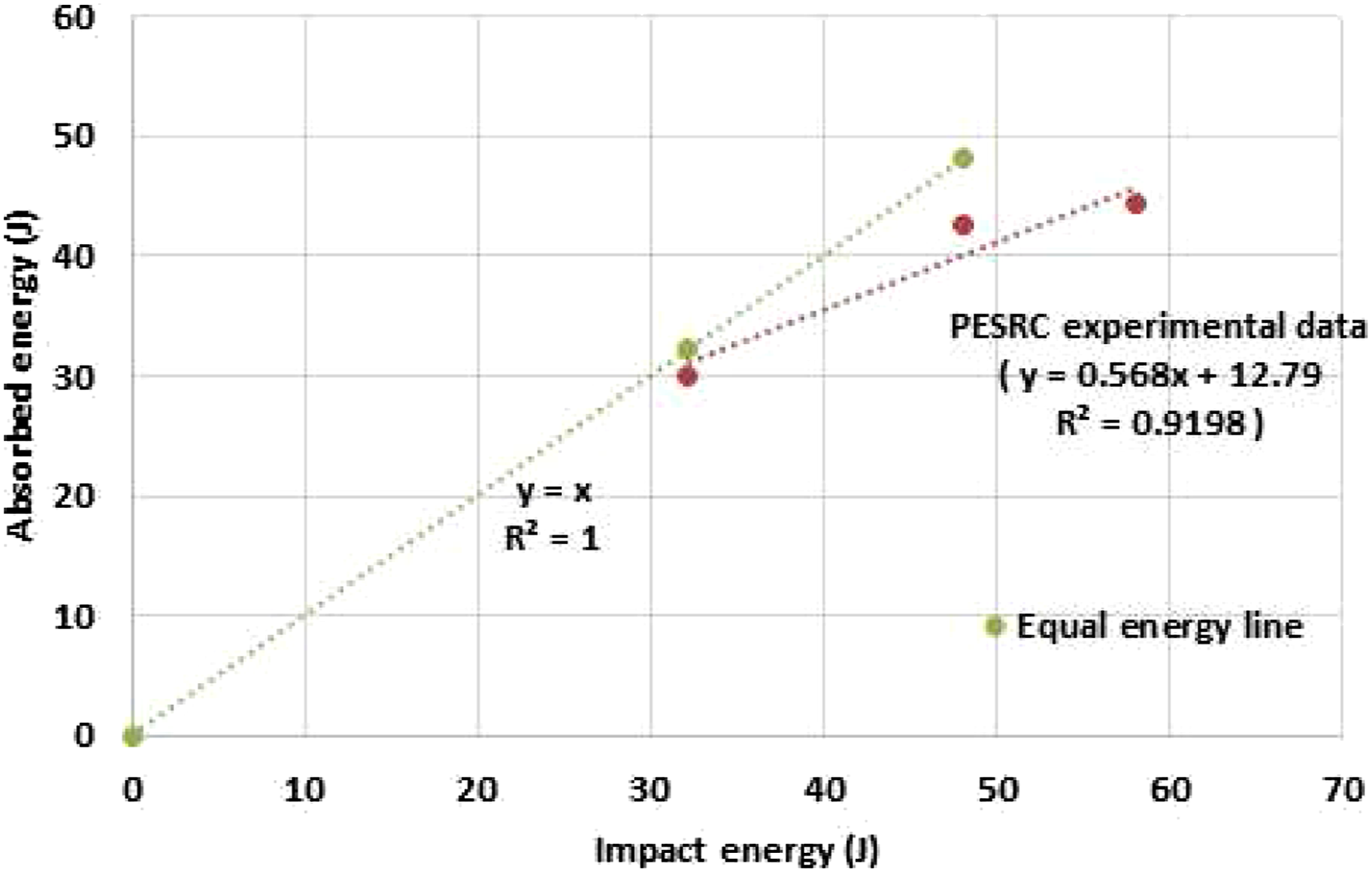
Quasi-static to dynamic property correlation
The investigators have published quasi-static mechanical properties and analyses of interfacial properties of the same PESRC laminates.29,30 Interfacial properties of PESRC were also evaluated by using meso-mechanical Micro bond multiple fibre pullout tests.32–35 Laminate-level quasi-static properties like tension, flexural properties, and in-plane shear properties were evaluated in the above-stated work (Figure 12). Interfacial properties like bond strength, interfacial shear stress and frictional parameters were evaluated by using multiple fibre pullout tests. Drop mass impact is a dynamic flexural loading condition which also induces high strain rate tensile and compressive stresses on the laminate. It also causes in-plane shear stresses and fibre pullout. It would be interesting to check the correlation in absorbed energy in these systems with respect to size and rate effects, which will be useful in analyzing the importance of the deterministic influence of interfacial properties and quasi-static mechanical properties on the laminate level dynamic characteristics like load and energy considerations. Sample Stress-strain plot of (a) tension and (b) Flexural test.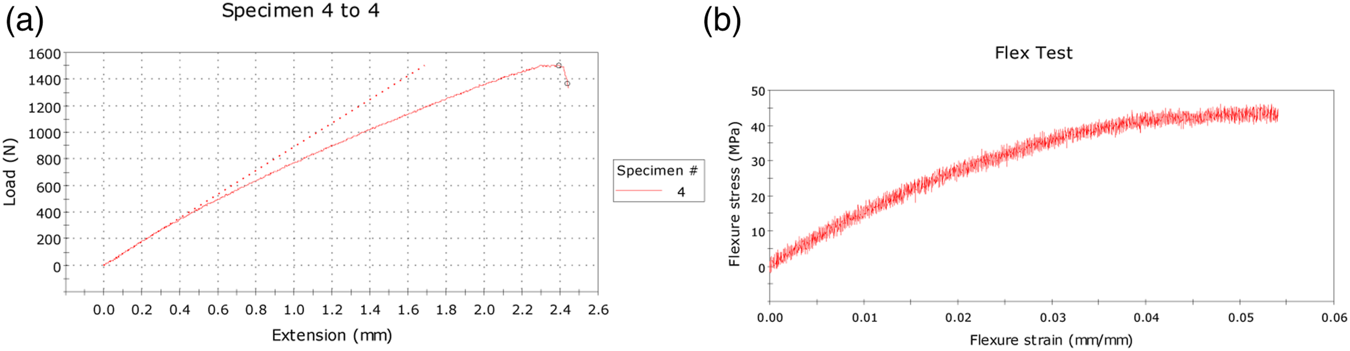
From the authors' previously published work on PESRC the energy absorption capacities in interfacial and quasi-static loading conditions of PESRC were found to be 0.004 J during the meso mechanical micro bond pullout test and it was influenced due to a lubricating nature of PE that has a low coefficient of sliding between the matrix and the fibre. If we compare PESRC with PPSRC (polypropylene SRC), it should be noticed that the interface is stronger in PPSRC than PESRC as per our previous study. An average of 1.56 J of energy was absorbed during the tension test of PESRC with less deformation and lower average maximum load compared to PPSRC of the same dimensions and volume fraction. Energy absorbed in In-plane shear of PP SRC is calculated to be 1.49 J, and that of PESRC is 0.75 J which is around half of PPSRC, indicating a weaker interface of PESRC again. The average energy absorbing capacity of PESRC is around 3 times that of PPSRC under drop weight dynamic loading. This can be correlated with the flexural test data. PPSRC absorbs around 0.45 J under quasi-static three-point flexural loading, which is 33 times lower than the critical energy absorbing capacity under dynamic loading. PE SRC shows a slightly higher energy absorbing capacity of 0.490 J in quasi-static flexure, a value 90 times lower than its dynamic loading capacity. A weaker fibre-matrix interface appears to increase the energy absorbed in flexure and drop weight impact for the PESRC. PESRC samples are characterized by a lesser elastic mismatch between the fibre and the matrix, a lower coefficient of the fibre and matrix surfaces and a lower intrinsic bond strength. Hence, the load-deflection plot is a result of accommodative deformation till maximum load, which tends to preserve the intrinsic bond strength due to the compressive nature of transverse loading on the face of the laminate.
For rebounding specimens of PE SRC, velocity takes a negative value. For the specimens with perforation, velocity becomes zero as the drop mass gets embedded in the specimen. An increase in impact velocity is reported to have an adverse effect on the stiffness properties of the materials. 6 For the rebounding specimen (PE SRC), displacement decreases after reaching a maximum. Deflection increases gradually and stops at a maximum in the penetration case, which can be seen in PE SRC plots under 58 J. By measuring this value, the distance up to which the penetration occurred can be determined.
Damage analysis
Visual inspection
Damage processes in PE SRCs are analyzed by visual inspection, light source inspection, and microscopic analysis and damaged area analysis. There are three fundamental damage processes according to the literature such as matrix mode, delamination mode and fibre damage.
4
Analyzing the failure mode also provides information about the residual strength of the material. Figure 13 explains the various types of failure occurring under three different energy levels for PE SRC. Failure images and analysis of PE SRC at different energy levels.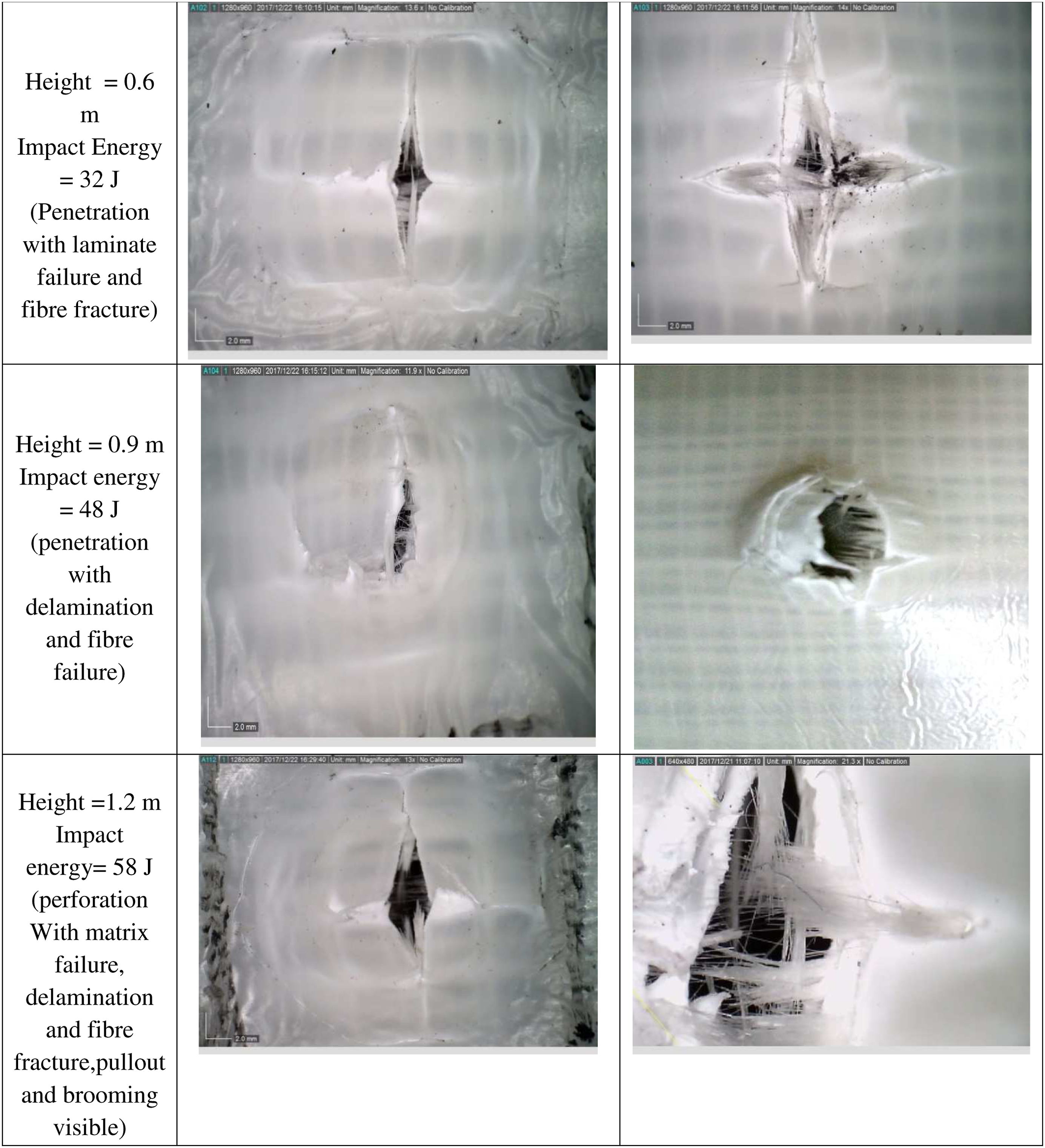
The damaged area is analyzed under optical microscopy, and the area is plotted after marking the damaged area under a transmitted light source. It can be observed that the damage in PE SRCs is more localized and ductile in nature, supporting the previous analysis. Stress whitening fields were not much widespread (Figure 14). Damage in PE SRCs was mostly radial in fracture, but fibrillation and fibre bridging were also noticed in the damaged area, added to the energy absorption characteristics due to the drop weight impact. Stress whitening and peripheral fracture lines were an indication of the identification of the damaged area. Absorbed energy versus Damaged area (PE).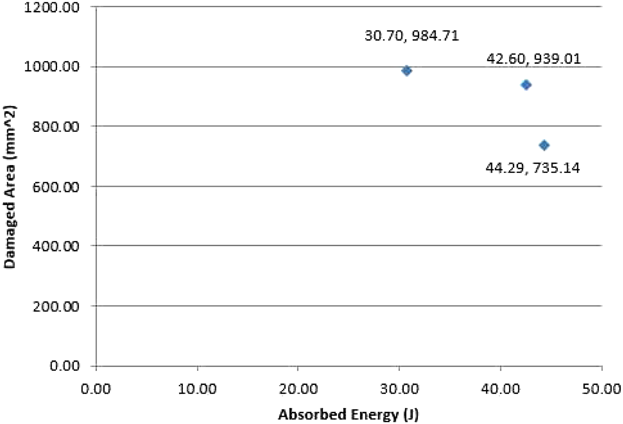
Through transmission C scan
For PE SRCs, the Damage area is expected to be more for higher impact energy. The energy-absorbing nature of the laminate can be well understood from Figure 13, which relates the absorbed energy and the measured damaged area. When the energy absorbed is more, the damaged area seems to be reduced. This indicates more localized damage and reduced propagation in PESRC. The damaged area was measured by using a light source and dynolite. Visual inspection also revealed that the damage at lower energy levels was more spread on the surface, while at higher energy impact, the damage was more localized at the location of penetration. This indicates that at lower impact energy, the laminate has a capacity to dissipate energy over the surface and resist the propagation of the failure to deeper levels. When the energy is as high as the critical energy, the tup penetrates deep into the laminate, and the energy is spent in the penetration failure mechanisms. For greater energy localized damages, fibre fibrillation and fibre bridging were predominately seen in the PE SRC.
C-scan images in Figure 15 indicate that at a lower energy level of impact, the damage has been widespread over the surface of impact and when the energy of impact increases, the damage becomes more localized. At low energy impact, the material resists the deformation, and the energy of impact spreads through the surface, causing matrix and fibre yielding along with local delamination. At higher impact energy, the material does not get enough time to resist the deformation, and the tup penetrates through the laminate in a short interval of time. This causes the energy to be spent in penetration or perforation with localized damages of matrix cracking, fibre fracture and fibre pullout rather than delamination and plastic deformations of other parts of the laminate. Internal damage identified through C-can.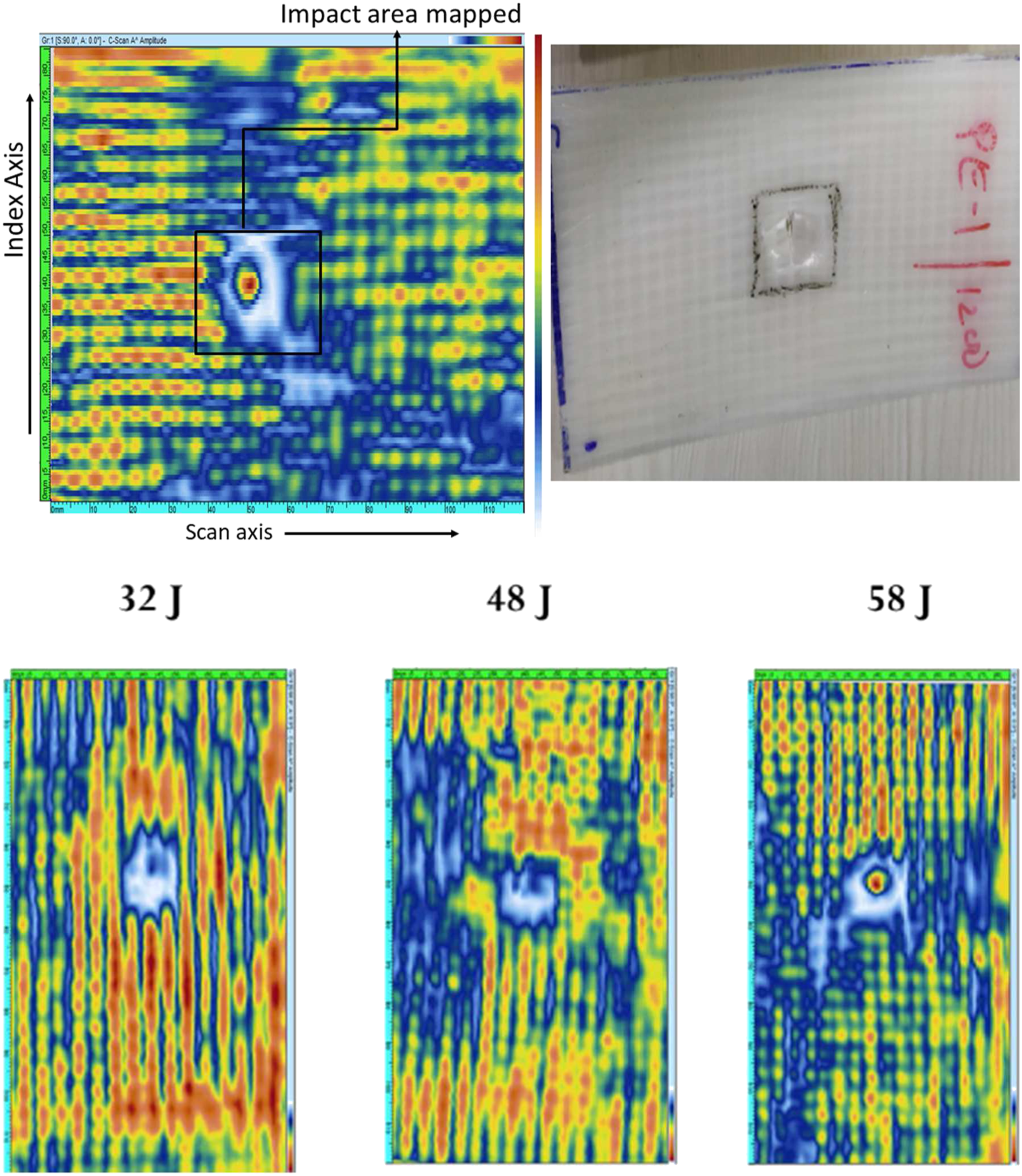
Information obtained from the cross-sectional view through the impacted eye of the laminate, as shown in Figure 16, adds to this observation. Additionally, crack initiation, propagation and fracture process can be clearly visualized. Crack has initiated at the bottom layer, which was subjected to tensile stress due to its weak tensile strength compared to compressive strength under transverse loading. Cross section of failed samples cut through the impact eye brooming can be clearly identified at higher energy impact.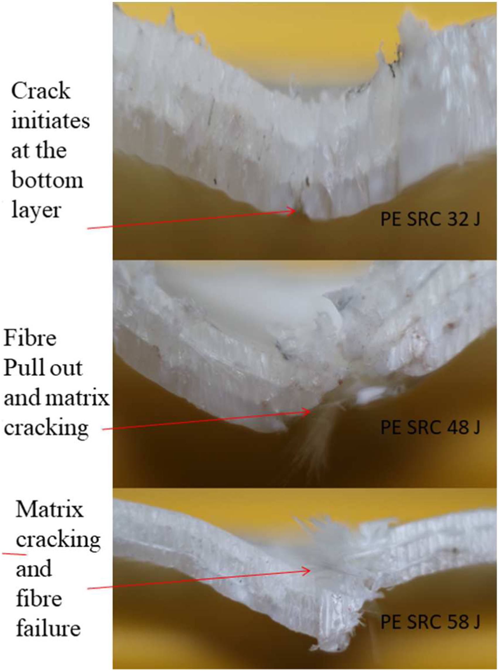
Scanning electron microscopy analysis
Post-failure Scanning electron microscopy (SEM) analysis was carried out to conceive detailed microscopic features of failure. Samples were extracted carefully at a constant distance away from the impacted region in order to get a microstructural insight into the failure patterns. Samples were selected from mutually perpendicular directions of the same sample to analyze the variation in failure patterns in these mutually perpendicular directions.
Figure 17(a) shows the surface after impact with a strain flow for PE SRC. Fibre bundle failed in a brittle nature under dynamic loading accompanied by appreciable pull out (b). Due to excessive unbalanced shear in the cross-section between the matrix and the fibre, the neutral axis seems to be dislocated (c) under impact due to the drop mass. Inner surfaces seem to experience appreciable matrix flow after failure, and pulled-out fibres are also visible (d). Fibre cross-section after impact is visible in Figure 17(e). Irregular matrix flow is another effect of the drop mass impact loading (Figure 17(f)). Fractography is thus able to corroborate the observed test data with the observed fracture features as PE SRCs are more elastic-plastic in nature. SEM images of PE SRC (post-failure).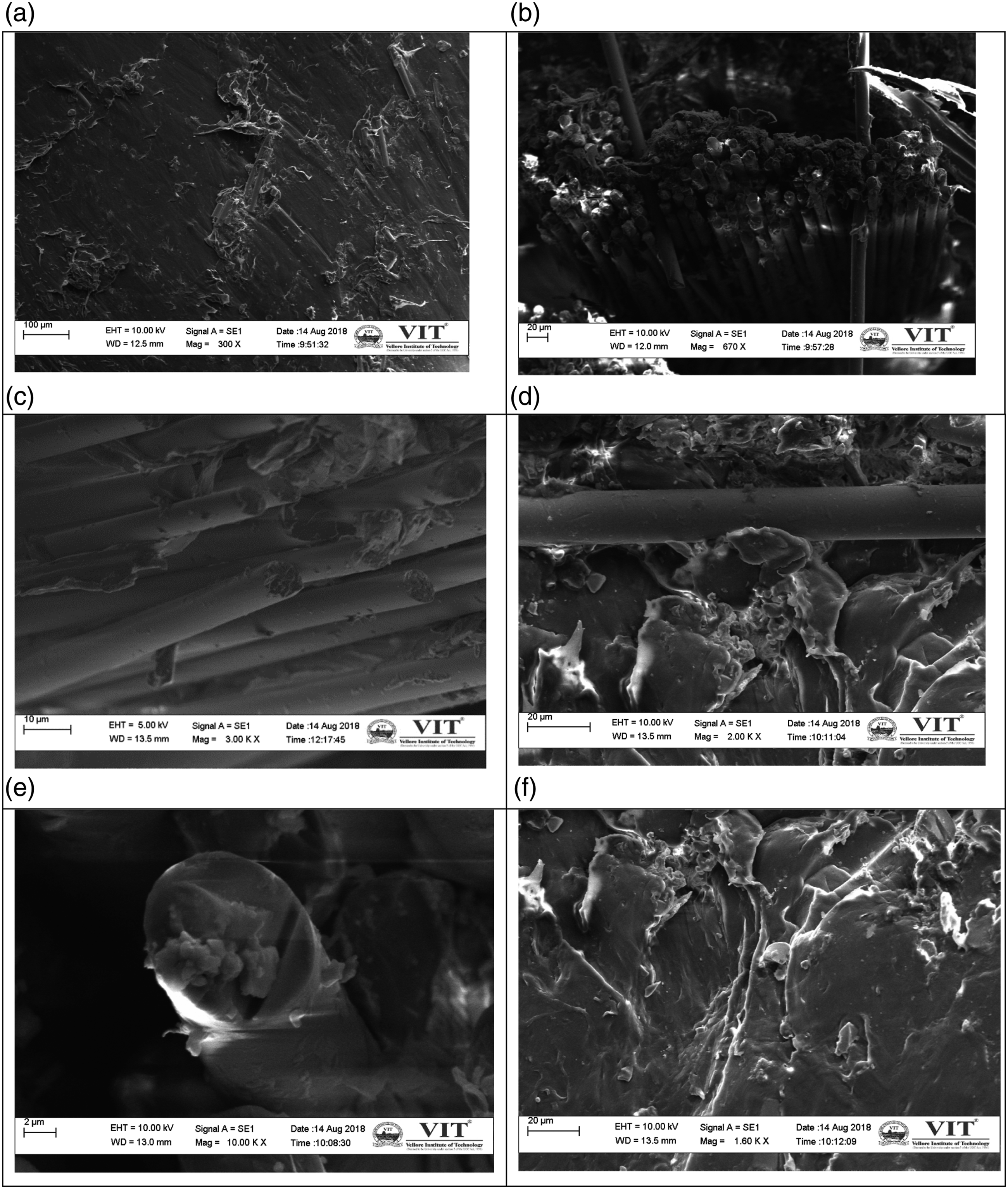
Interfacial shear strength is an important property to be considered while analyzing the interfacial properties of composite materials. PESRCs do not show any noticeable initial failure till a maximum load is achieved under dynamic loading due to an accommodative nature of deformation between the fibre and the matrix till a large deformation is reached. This is also due to its elastic-plastic nature. Interfacial bond strength is the strength of the interface against its first failure. In PE SRC, it happens only at the maximum dynamic load. If the interfacial adhesion is further improved in PESRCs, the energy absorbing capacity of these composites can be significantly improved. An indication of this behaviour was observed in a previous interface analysis of these composites, and the dynamic loading characteristics carried out here also verify this comparative analysis. Performance of various self-reinforced composites with interface perspective has been enlisted by the authors in a recently published book. 36
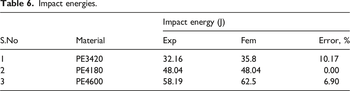
Impact energies.
Average max load and absorbed energy.
Damage area comparisions.
Energy per unit area.
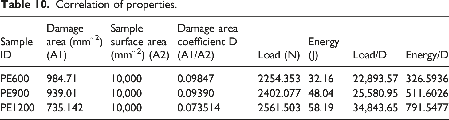
Correlation of properties
Interfacial properties like bond strength, interfacial shear stress and frictional parameters were evaluated by using multiple fibre pullout tests. Drop mass impact is a dynamic flexural loading condition which also induces high strain rate tensile and compressive stresses on the laminate. It also causes in-plane shear stresses and fibre pullout. It would be interesting to check the correlation in absorbed energy in these systems with respect to size and rate effects, which will be useful in analyzing the importance of the deterministic influence of interfacial properties and quasi-static mechanical properties on the laminate level dynamic characteristics like load and energy considerations.
PESRC sample is characterized by a lesser elastic mismatch between the fibre and the matrix, lower coefficient of the fibre and matrix surfaces and lower intrinsic bond strength. Hence, the load-deflection plot is a result of accommodative deformation till maximum load, which tends to preserve the intrinsic bond strength due to the compressive nature of transverse loading on the face of the laminate.
Correlation of properties.
Conclusions
The high energy absorption at very low densities (lighter than water), which indicate a high specific absorption value in low-velocity impact tests of PE SRCs, means that they can be used in cargo and luggage applications in the marine and aerospace domains at affordable costs with hybridized or single reinforcements. If all the luggage were made of PP and PE SRCs, the entire luggage would float, thereby enabling easy detection and recovery. These would also provide lifebuoys for survival till assistance arrives. 1. Damage is more localized in PE SRCs.When the impact energy increases, the growth of the damaged area has been slightly reduced, indicating the energy is more spent on various failure mechanisms. Damage growth is restricted within a small area even under higher energy levels by utilizing the energy for fiber fracture, bridging, fibrillation and matrix cracks. It was noticed that at the higher impact energy levels, surface damage on PESRC is seen, and most of the energy is spent in perforation, reducing the impact on the surface. This also indicates that a weak nature of the interface assists in a localized perforation. Hence, PE SRCs are a better choice for dynamic loading conditions. The weak interface of fibre and matrix causes fibre pullout under impact loading. 2. Energy profile diagrams and damaged area analysis are very useful in predicting the behaviour of the elastic-plastic SRC composite materials subjected to dynamic loading. 3. The matrix flow and a considerable shift of the neutral axis of the fibres were observed in the PE SRC, and pull outs of the fibre bundle were common. Fractography is thus able to corroborate the observed test data with the observed fracture features as PE SRCs are elastic-plastic, which are seen through the load time and load-displacement plots as well. 4. A high specific absorption value in low-velocity impact tests of PE SRCs renders them useful in cargo and luggage applications in the marine and aerospace domains at affordable costs. 5. The numerical model is able to predict the low-velocity impact response, energy absorption characteristics and amount of deflection of the laminates due to drop weight impact in a computationally cost-effective manner. 6. The post-impact damage mechanisms and delamination behaviour of PE SRC and other SRC systems can be studied without damaging the sample using the developed numerical model. 7. A correlative formulation useful for comparing the test results, predicting the extent of damage and material selection is proposed
Footnotes
Acknowledgements
We would like to thank Dr Rajesh Kitey, professor in-charge, and Mr Chandrapraksh Sharma, Structural lab, Department of aerospace engineering, IIT Kanpur for the drop weight tests. The management of VIT, Vellore and the Dean, SMEC, VIT, Vellore, are thanked for the support.
Funding
The author(s) received no financial support for the research, authorship, and/or publication of this article.