
Abstract
Low-velocity impact tests were carried out on filament-wound composite overwrapped pressure vessel (COPV) specimens at different impact energies and impact points to determine the low-velocity impact damages of wound composite structures. The anti-impact performance of the filament-wound COPV was compared with that of composite laminated and filament-wound composite plates. Different impact damage modes and damage mechanisms inside the wound COPV were investigated through ultrasound scanning, X-ray, and scanning electron microscopy. Results showed that the impact force–time response curve of the wound COPV can be divided into an ascending area, a plateau area, and a descending area. The duration of the plateau area increased with the increase in impact energies. The impact resistance of the filament-wound COPV was the best, followed by that of the composite laminated plate, and the filament-wound composite plate was the worst. The major damage modes of the filament-wound COPV under low-velocity impact included matrix breakage, delamination, and fiber breakage. Delamination in the COPV tube section mainly occurred between the spiral wound and hoop layers. Delamination at the head of the COPV occurred between different winding layers. Fiber breakage inside the COPV mainly developed in the fiber overlapping zone inside the spiral layer. Results indicated that the fiber overlapping zone was the weak part in the filament-wound composite structure.
Introduction
Carbon fiber composites have been widely used in the aerospace, automobile, rail traffic, and energy fields due to their good specific strength, specific stiffness, and corrosion resistance.1,2 Nevertheless, these composite structures are highly sensitive to mechanical impact loads. Even though no visible damage is left on the external surfaces of these structures at low impact energies, some damages, including matrix cracking, delamination, and fiber breakage, develop inside the structures, thus decreasing their structural strength considerably.3,4 During practical use, filament-wound composite overwrapped pressure vessels (COPVs) are inevitably impacted by foreign bodies in different processes, such as the falling off of instruments, the collision of equipment, and the impacts of splash rocks. These impacts all cause potential threats to the safety of the structures and increase the failure risk of the composite structures. Therefore, studying the low-velocity impact behavior and failure mechanism of wound COPVs is highly important.
Studies on low-velocity impact response and damage behaviors can provide theoretical support for the design of composite structures and improve the safety and reliability of products. Investigations on the impact response and failure of composite laminated plates have matured. Amaro et al. 5 performed a low-velocity drop-weight test on laminated plates with orthogonally paved carbon fibers and investigated the influences of different boundary conditions on the impact damages of the composites. Pegoretti et al. 6 determined the relationship between the impact energies of toughening laminated plates and impact fracture toughness through a pendulum impact test. Lopes et al. 7 analyzed the influences of different pavement directions on the impact performances of laminated plates by conducting a low-velocity drop-weight test. Rivallant et al.4,8,9 investigated the low-velocity impact response laws of composite laminated plates and analyzed the influences of impact damages on the compressive strength of the laminated plates. Liao et al. 10 discussed the influences of the impact angle of bar-shaped impactors and the diameter of hemispherical impactors on the impact mechanics of carbon fiber-reinforced composite laminated plates and investigated the characteristics of laminated low-velocity impact damages on the basis of pit depth and delamination area. Borkowski et al. 11 constructed a coupling analysis model of the impact damages and post impact strength of laminated plates and verified it experimentally. The failure criteria and damage evolutionary behaviors of composite laminated plates under low-velocity impact were investigated through damage characterization by introducing an equivalent damage volume. 12
A wound composite structure is different from a composite laminated plate. The technological conditions during the preparation of the wound composite structures are difficult to control. Given that applying pressure on curved surfaces is difficult, the end product has high porosity and vibration. Therefore, the low-velocity impact failure of wound composite structures is significantly different from that of laminated plates.
Gning et al. 13 discussed the responses of a thick-walled cylinder of a ±55° composite to lateral impacts and found that the first delamination developed when the impact energy reached 4 J. With the increase in impact energies, the delamination propagated gradually, and the cracks inside the layer increased accordingly. Lin and Li 14 investigated the impact responses of laminated plates with different curvatures and found that bending deflection decreased, whereas deformation increased with the reduction in the radius of curvature. Kara et al. 15 studied the low-velocity impact behaviors of pure carbon fiber/epoxy tubes and multiwalled carbon nanotube-reinforced carbon fiber/epoxy tubes at different temperatures. Their results showed that decreasing the temperature and adding multiwalled carbon nanotubes into the epoxy matrix could increase the rigidity of the materials. Almeida et al. 16 manufactured variable-angle cylinders through filament winding process, and carried out an axial compression test with displacements and strains measured by digital image correlation (DIC). Their results showed that buckling strength, stiffness, and absorbed energy of variable-angle cylinders substantially higher than the constant-angle configuration. Almeida et al. 17 studied the effect of hygrothermal conditioning on tensile, compressive, in-plane and interlaminar shear properties of carbon fiber/epoxy laminates. Azevedo et al. 18 studied the influence of the winding pattern on the axial compressive behavior of filament wound composite cylinder under hygrothermal conditioning. Castro et al. 19 proposed a novel imperfection measurement method which is simple and applicable to both small and large structures. Stedile Filho et al. 20 investigated the mechanical behavior of carbon/epoxy composite drive shafts manufactured by filament winding under torsion and radial/axial compression, and the [±45/±45] cylinder showed the best performance under torsional loading. Mokhtar et al. 21 studied the influences of winding angles, impact energies, hemispherical impactor diameter, and lateral impact loads on basalt fiber wound tubes. Lin et al. 22 investigated the relationships of impact energies and supporting conditions with impact damage characteristics and residual compressive strength after impact. Zhang and Tan 23 studied the influences of impactor shape on the impact damages of composite tubular structures and found that hemispherical impactors caused local damages, whereas cylindrical impactors caused global damages. Choi and Kwon 24 monitored the low-velocity impact damages of wound composite shells by using a distributed fiber Bragg grating. Li et al. 25 carried out an experimental study on the low-velocity impact damages of fiber-reinforced stressed-skin constructions. They pointed out that impact points influenced the damages of the specimens considerably and that the damage modes of the specimens differed at different impact points. Liu et al.26,27 analyzed the low-velocity impact damage problems and residual strength problems of wound composite shells after impact by combining experiments and simulation. They also constructed a model of the damage inside the composite surface that considered the Weibull distribution of material strength and the integrated analysis model of residual strength after impact. Their calculated results conformed well with their experimental results. Wu et al. 28 found that given the same impact energy, flat-bottomed impactors caused higher energy dissipation than hemispherical and cylindrical impactors. They discovered that the major failure modes of the composite included compression, shearing, stretching, and impacting failures. Ribeiro et al. 29 carried out an experimental study on the impact behavior of composite gas cylinders and found that under impact loads, the composites developed different damages, including delamination, matrix cracking, and indentation. Moreover, impact behavior was highly sensitive to pavement sequence. In practice, gas is often present in the composite gas cylinder upon impact. Some studies have demonstrated that gas cylinders with internal pressure receive more damage than those without internal pressure. 30 Kobayashi et al. 31 studied the influences of pavement thickness on the low-velocity impact mechanical performances of carbon fiber-reinforced composite gas cylinder tubes. They concluded that stiffness is positively related to thickness and that the energy dissipation of gas cylinders after thickness regularization is positively related to fiber damage depth. YongMing et al. 32 discussed the impact energy absorption rate and delamination extension resistance of gas cylinder shells during low-velocity impact.
The low-velocity impact response and damage mechanism of wound COPVs are complicated. The differences of these COPVs from laminated plates need further studies. Therefore, in this work, low-velocity drop-weight impact tests on wound COPVs, composite laminated plates, and wound composite plates were designed and carried out at different impact energies and impact points. The low-velocity impact damages of wound COPVs were analyzed through the comparison of the low-velocity impact response laws and damage modes of the three specimens. Different damage modes inside the COPV were detected by using ultrasound, X-ray, and scanning electron microscopy (SEM) techniques to discover the low-velocity impact damage mechanism of wound COPVs.
Materials and methods
Test materials and specimens
Filament-wound COPV, composite laminated plate, and filament-wound composite plate specimens were designed and prepared by using T700 carbon fiber and epoxy resin from Toray, Japan. These specimens were used to compare the impact damage characteristics of filament-wound composite structures.
(1) Laminated plates were prepared through the prepreg of T700 carbon fiber/epoxy resin. The specimens had a pavement sequence of
(2) Wound COPV specimens were prepared through the wet winding of T700 carbon fiber/epoxy resin in a certain linear mode. Each specimen was composed of a cylinder section and head. The winding pavement angle of the cylinder section was
(3) Filament-wound composite plate specimens were prepared on the basis of the fiber-wound COPVs. After the winding of the COPV was completed, the two heads were eliminated before solidification, and the composite cylinder is then cut along the shaft and laid flat. Then, compressed solidification was performed. Subsequently, the sample was cut into 150 mm × 100 mm plate specimens through water cutting. The specimens had a mean thickness of 2.1 mm and the pavement sequence of

Composite laminated plate specimen: (a) dimensional diagram and (b) specimen.

Filament-wound COPV specimen.

Schematic diagram of filament wound flat specimen: (a) schematic diagram of processing and (b) specimen.
Low-velocity impact test
Experimental apparatus and holders
The low-velocity impact test was carried out in reference to the standards compiled by the American Composite Committee. 33 The tester mode was INSTRON Dynatup 9250HV (Figure 4), which was equipped with an antisecondary impact device. A hemispherical impactor with a diameter of 12.7 mm was selected. The total mass of the counterweight impactor was 6.5 kg. The impact energy was determined on the basis of the initial height difference between the impactor and specimens. Load and acceleration sensors were installed inside the impactor to collect relevant data in the impact tests.

Low-velocity drop-weight impact test devices.
Plate sand specimen holders for the wound COPVs were manufactured for convenient specimen fixation (Figure 5). A steel holder with a 125 mm × 75 mm opening in the center and simple supports at four sides was used for plate specimens. The holder was fixed onto the drop-weight tester by bolts. The wound COPV specimens were fixed by rings and bolts at two ends of the holder to prevent overall movement in the impact process. A 10 mm space was introduced between the COPV and the bottom of the holder to prevent their collision.

(a) Plate specimen holder, (b) COPV structure holder, and (c) holder size of the COPV and impact points.
Test steps
Low-impact tests with different energy levels were designed. The specific test parameters are listed in Table 1. The impact points of the laminated and wound composite plates were located at the center of the specimens. The impact points of the wound COPV are as follows: Impact point #1 was located at the center of the tube section of the COPV; impact point #3 was found at the equator circle of the COPV head; and impact point #2 was located between impact point #1 and #3 (Figure 5(c)). Before the impact test, defects in specimens were detected by using ultrasonic nondestructive testing technology to ensure that the specimens were in a perfect state.
Parameters of the low-velocity impact tests.

Damage detection
The specimens were detected after the low-velocity impact tests. First, the points and sizes of the defects were determined by ultrasonic wave detection. The composite laminated plate and the filament-wound composite plate were detected by air-coupled ultrasonic C-scanning at a frequency of 200 kHz. Two probes were placed on both sides of the plate, and the ultrasonic waves were incident perpendicular to the plate. The ultrasonic detection of the filament-wound COPV was performed by using a small portable ultrasonic A scanning device with a probe diameter of 20 mm and a frequency of 200 kHz, as shown in Figure 6. During detection, the impact point was used as the center of a circle, and scanning was extended outward gradually until arriving at the damage boundaries. The detected damage edges were denoted one by one. Second, the axial section of the wound COPV was tested by using an area array X-ray detection device to determine the damage mode. Finally, the damage modes inside the filament-wound COPV after the impacts were distinguished via SEM (JSM-646LV).

Portable Ultrasound A Scanning device.
Results and discussion
Low-velocity impact response laws of filament-wound COPVs
Variation laws of the impact force–time curve
The impact force–time curves of impact point #1 of the wound COPVs at different impact energy levels are shown in Figure 7. As can be seen from Figure 7(a), when the impact energies were between 5 and 15 J, the impact force–time curve was relatively smooth and approximated a dome. When the impact energies were between 20 and 35 J, the curve oscillated repeatedly at the maximum impact force, and the oscillation lasted for a period. Under this condition, the impact force–time curve generally can be divided into three parts: an ascending area, a plateau area, and a descending area (Figure 7(b)). The curve in the ascending area was approximately linear. Before the development of the initial damage, the impact force increased rapidly with time, and initial damage occurred when the impact force reached approximately 1 kN, thus changing the slope of the straight line. The growth rate of the impact force decreased with time until the maximum impact force (2.6 kN) was reached. The curve entered the plateau area, where the impact force oscillated repeatedly around the maximum impact force. The gentle oscillation of the impact force could be attributed to the continuous development of damages inside the COPV. However, such damages were insufficient for the loss of the overall bearing capacity of the COPV structure. After a certain period, the impact force decreased quickly with time. Under this condition, the internal energy of the COPV began to be transform into the kinetic energy of the impactor until the COPV was separated from the impactor.
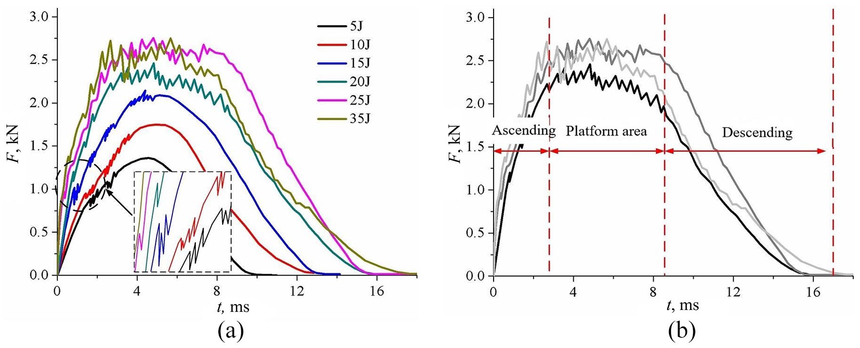
(a) Impact force–time curve at different impact energies and (b) division of the impact force–time curve at point #1 of the COPV.
As can also be seen in Figure 7(a), with the increase in impact energies, the slope of the ascending area increased gradually and the duration of the plateau area was also prolonged, whereas the descending area changed from smoothly declining to oscillating declining. Moreover, the impact force between the impactor and COPV increased gradually with the increment in impact energies. However, when the impact energy exceeded 20 J, the maximum impact force no longer increased with the increase in impact energies, whereas the impact time increased continuously. In this way, the COPV structure had sufficient time to absorb the kinetic energy of the impactor, and damages inside the COPV structure would surely increase continuously with the increase in impact energies.
The impact force–time curves at points #2 and #3 of the COPV at different impact energies are shown in Figure 8. Comparison with the curves in Figure 7 revealed that the impact force–time curves at three points presented consistent variation trends at different impact energies, and all developed plateau areas similar to those analyzed above when the impact energy was relatively high. Moreover, the maximum impact forces at points #1 and #2 were relatively close, whereas the maximum impact force at point #3 was significantly lower than that at the other points. The disappearance of the hoop layer of the COPV tube section at the head equator where point #3 was located resulted in significant changes in local thickness. Therefore, the impact force at point #3 was far lower than the impact forces at the remaining two points.

(a) Impact force–time curve for the point #2 of the COPV and (b) impact force–time curve for point #3 of the COPV.
For the comparative analysis of response laws, the impact force–time curves of the filament-wound COPV, filament-wound composite plate, and laminated plate specimens at the impact energy of 5–20 J were compared (Figure 9). As can be seen from Figure 9, when the impact energies were 5 and 10 J, the impact force–time curves of the wound composite and laminated plates were similar. The sharp decline in the impact force of the filament-wound composite plate after reaching the maximum (Figure 9(c) and (d)) when the impact energy was 15 J. However, the composite laminate plate did not exhibit similar phenomenon until the impact energy was 20 J, which indicated that the anti-impact performance of the filament-wound composite plate was inferior to that of the composite laminated plate.

Comparison of the impact force–time curves of the three kinds of specimens at different impact energies: (a) 5 J, (b) 10 J, (c) 15 J, and (d) 20 J.
Figure 9 shows that at the same impact energy, the impact force between the impactor and COPV structure was significantly lower than that between the plate specimens and impactor. Moreover, the impact force–time curves of the plate specimens lacked plateau areas. This pattern demonstrated that the impact response time inside the plate structure was shorter than that in COPV structure. As a result, the area of the plate structure that was influenced by the impact was more concentrated than that of the COPV structure.
Variation laws of central displacement–time curves
The central displacement–time curves at three points of the filament-wound COPV and different impact energies are presented in Figure 10. Clearly, the central displacement-time curves were approximately parabolic. With the increase in impact energies, the maximum central displacement increased gradually, and the slope of the ascending area increased accordingly. When the central displacement reached the maximum, the curves entered the descending area. With the increase in impact energies, the duration of the descending area prolonged continuously. When the impact energy was 35 J, the slope of the descending areas at points #1 and #2 was significantly lower than that of the ascending area. This result indicated that damages had developed inside the specimens during impact such that the elastic properties of the specimens declined and impact rebounding was prolonged.

Central displacement-time curves of the COPV specimens at different impact energies: (a) point #1 of the COPV, (b) point #2 of the COPV, and (c) point #3 of the COPV.
The central displacement–time curves of the laminated plate, filament-wound composite plate, and filament-wound COPV specimens under low-velocity impact are shown in Figure 11. The filament-wound COPV presented the maximum central displacement under the same impact energy. For the filament-wound COPV, the central displacement at point #3 was the maximum, followed by those at points #1 and #2. When the impact energies were 5 and 10 J, the slopes of the ascending and descending areas of the central displacement–time curves of different specimens were similar, and the shapes of the curves were similar to a regular parabola. The significantly lower slope of the descending area of the filament-wound composite plate than that of the ascending area at the impact energy of 15 J indicated that internal damages had developed. When the impact energy was 20 J, the slope of the descending area of the composite laminated plate also declined significantly. The comparison of the central displacement–time curves of different specimens showed that the elastic properties of the tube section (points #1 and #2) of the filament-wound COPV did not decrease significantly when the elastic properties of the composite laminated and filament-wound composite plates declined. This phenomenon revealed that the anti-impact performance of the tube section of filament-wound COPV was relatively good.

Comparison of the central displacement–time curves of specimens at different impact energies: (a) 5 J, (b) 10 J, (c) 15 J, and (d) 20 J.
Variation laws of impactor kinetic energy–time curves
The impactor kinetic energy–time curves of the three specimens at different impact energies are shown in Figure 12 (the impact energies along the y-axis were normalized). During impact, the energies are absorbed by the specimens mainly through damage consumption, oscillation, and friction wearing, and local plastic deformation. Specifically, damage consumption inside the specimens accounted for the highest proportion of energy consumption. The absorbed energies in the same specimen were approximately proportional to the degree of internal damages. As shown in Figure 12, the filament-wound composite plate and composite laminated plate absorbed the highest amount of energies at the same impact energy level. At the impact energy of 20 J, the filament-wound composite plate and laminated plate absorbed the highest amount of kinetic energies during impact. Large-scale fiber damages had occurred in the postimpact specimens.

Impactor kinetic energy–time curves at different impact energies: (a) 5 J, (b) 10 J, (c) 15 J, and (d) 20 J.
As can be seen from Figure 12, at the same impact energies, point #3 of the filament-wound COPV absorbed the lowest energies, whereas point #1 absorbed the highest energies. The absorbed energies at point #2 were between those absorbed at points #1 and #3. The comparison of the variation laws of impactor kinetic energies in the impact process of the three specimens in combination with the damage conditions on specimen surface revealed that the filament-wound COPV showed the best impact toughness and absorbed less kinetic energies during impact than plate specimens. Moreover, the COPV retained integral structures after impact. The anti-impact performances of the COPV specimens were closely related to the impact point. The absorbed energies at different points during the impact process varied, and the degree of internal damages was also different.
Analysis of the impact damage mode of the filament-wound COPV
Detection results for the impact damage areas of different specimens
The damage images of the COPV are shown in Figure 13. Clearly, the distribution pattern of the internal damages of the filament-wound COPV around the impact point showed an approximately oval shape. In the COPV tube section, the long axis of the oval was consistent with axial direction of the COPV. At the equator circle of the COPV head, the long axis of the oval was approximately consistent with the annular direction of the COPV.
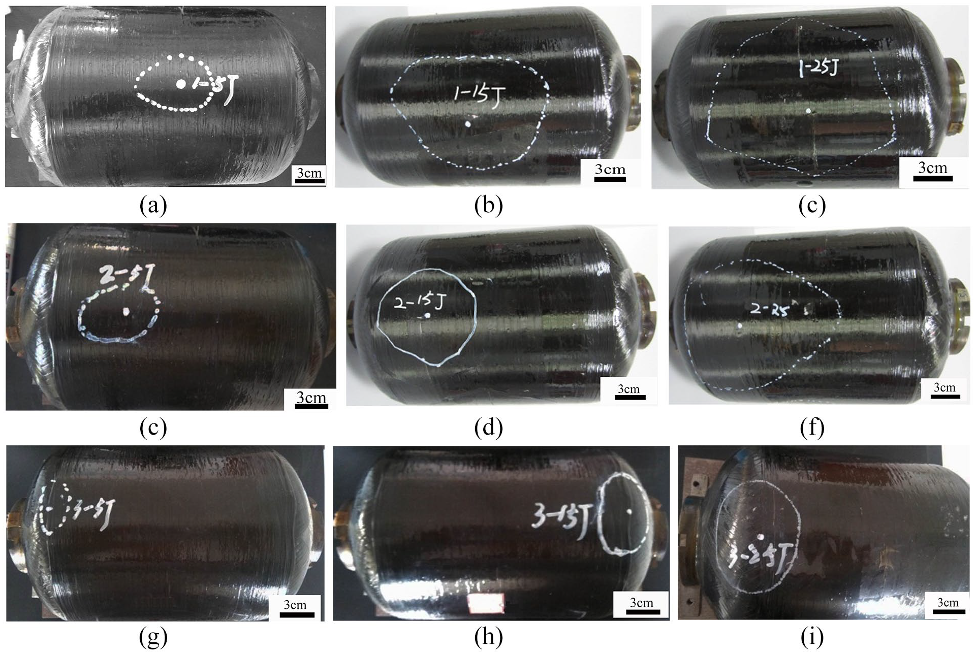
Ultrasonic scanning detection results of the filament-wound COPV after impact: (a–c) point #1, (d–f) point #2, and (g–i) point #3.
The damages detected through ultrasonic scanning were plotted on transparent coordinate paper. The damage area inside the COPV was calculated approximately and compared with the damage areas of the composite laminated plate and filament-wound composite plate. The results are shown in Figure 14. At the same impact energies, the damage areas of the composite laminated and filament-wound composite plates were significantly smaller than those of the tube section of the filament-wound COPV (points #1 and #2). In the wound COPV, the damage area at point #1 was the largest, followed by those at points #2 and #3. As can be seen from changes in the impact damage areas with impact energy, when the impact energy was smaller than a given value, the impact damage area presented an approximately linear relationship with impact energy. When the impact energy was increased to a certain value, the impact damage area basically remained constant mainly because when the impact energy was low, delamination and matrix damage were the major failure modes inside the composite. When the impact energy was higher than a given value, the produced impact force was sufficient to cause fiber breakage. Although fiber breakage absorbed most energies, the damage area did not expand significantly.

Statistics of the impact damage areas of the three kinds of specimens at different energy levels.
Impact damage modes at different points of the COPV
The X-ray detection results obtained at different points of the filament-wound COPV after impact with energies of 25 and 35 J are shown in Figure 15. As can be seen from Figure 15(a) and (c), after the tube section (points #1 and #2) of the COPV suffered an impact of 25 J, fiber breakage, which was manifested as obvious shearing breakage morphologies, occurred inside the COPV. Delamination mainly occurred between the loop layer and spiral wound layer. No obvious delamination was observed inside the spiral wound layer. No obvious concavities or convexities on the external and internal surfaces of the COPV were observed. When the impact energy was increased to 35 J (Figure 15(b)), internal damage near point #1 of the COPV intensified by various degrees, and a round area with fiber and resin breakage developed inside the COPV. Specifically, fiber breakage mainly occurred on the spiral wound layer, and matrix damage mainly occurred on the hoop layer. Bumps were found on the internal surface of the COPV at the impact point.

X-ray detection results of damages at different points of the COPV specimen: (a) point #1–25 J, (b) point #1–35 J, (c) point #2–25 J, (d) point #2–35 J, (e) point #3–25 J, and (f) point #3–35 J.
Observing the impact damage morphology at point #2 of the COPV in Figure 15(d) revealed the presence of fiber breakage and curling on the outer layer. Meanwhile, fiber breakage and delamination inside the COPV were very obvious. The spiral wound and hoop layers in the middle of the cross-section of the COPV showed the most serious damages. The morphology of the impact damage at point #3 of the COPV was significantly different from that at the tube section. After impact with an energy of 25 J, COPV delamination mainly occurred at the head (Figure 15(e)). Given the absence of an annular wound layer on the head of the filament-wound COPV, delamination occurred only between different spiral wound layers. When the impact energy was increased to 35 J, relatively obvious fiber breakage occurred on the inner side of equator circle near the head (Figure 15(f)).
Microstructural analysis of the impact damage of filament-wound COPV
The filament-wound COPV with damages caused by an impact of 25 J at point #1 was chosen. The COPV was divided along the annular and axial directions through waterjet cutting by taking the impact point as the center. The cut cross sections are shown in Figure 16. The hoop land spiral wound layers could be distinguished clearly. Moreover, delamination, which was produced during impact, was mainly located at the boundary between the spiral wound and hoop layers, and circumferential cracks were generated between the spiral wound and hoop layers, which is similar to the conclusion of Almeida et al. 34 Matrix damages were also observed near delamination.

Visual detection results of cross sections after COPV cutting: (a) axial profile and (b) annular profile.
Combining with X-ray detection results, the specimen was further cut. The microstructures and locations of different damage modes, such as delamination, matrix cracking, and fiber breakage, on the COPV were observed by using SEM. The results are provided in Figure 17. As can be seen from Figure 17(a) and (b) delamination mainly occurred on the boundary between the spiral wound and hoop layers. Delamination was also observed between the ±28° wound layers inside the spiral wound layer. However, the scope of delamination inside the spiral wound layer was small. As can be seen from Figure 17(c) and (d) matrix damages were also present inside the hoop layer and spiral wound layer. Obviously, matrix cracking and delamination developed at the same time. Matrix cracking mainly manifested in the form of shearing damages. The fiber breakage inside point #1 of the COPV at the impact energy of 25 J is shown in Figure 17(e) and (f). The location of the fiber breakage inside the spiral wound layer in combination with macroscopic observation results indicated that the fiber-overlapping area of the COPV near the impact point was the area that was most vulnerable to fiber breakage.

SEM images of different damage modes on the COPV specimen: (a and b) delamination, (c and d) Matrix cracking, and (e and f) fiber breakage.
Conclusions
Some major conclusions can be drawn from the low-velocity drop-weight impact and post-impact damage detection tests on the filament-wound COPV, filament-wound composite plate, and composite laminated plate specimens.
The impact force–time curves of the filament-wound COPV could be divided into an ascending area, a plateau area, and a descending area. The duration of the plateau area was positively related to impact energies. Given the same impact energy, the central displacement of the impact point at the equator circle of the head was relatively large, whereas that of the tube section was relatively small. Moreover, compared with other sections, the tube section of the COPV absorbed less kinetic energy, whereas the equator circle of head absorbed more kinetic energy.
At the same impact energy, the maximum impact force between the impactor and COPV was significantly lower than that between the impactor and plate. The greater maximum central displacement of the COPV than that of the plate indicated that the impact response laws of the composite structures were closely related to the shape, size, and boundary conditions of the structures. The filament-wound COPV generally demonstrated the best anti-impact performance, followed by the composite laminated plate and the filament-wound composite plate. At the same impact energy, the degree of damage inside the filament-wound composite plate was higher than that inside the composite laminated plate.
The major damage modes of the filament-wound COPV after low-velocity impact included fiber breakage, matrix damage, and delamination. When the impact energy was relatively low, only matrix damage and delamination existed inside the filament-wound COPV. The delamination of the COPV tube section mainly occurred between the spiral wound and hoop layers, whereas at the head of the COPV, delamination was present among different wound layers. When the impact energy exceeded a certain threshold, fiber breakage began to occur inside the COPV and mainly occurred in the fiber-overlapping region inside the spiral wound layer. This damage pattern revealed that the fiber-overlapping region was the weak point inside the filament-wound composite structure. Moreover, some fiber breakages existed on the COPV surface near the impact point.
Footnotes
Declaration of conflicting interests
The author(s) declared no potential conflicts of interest with respect to the research, authorship, and/or publication of this article.
Funding
The author(s) disclosed receipt of the following financial support for the research, authorship, and/or publication of this article: This research was funded by the Natural Science Foundation of the Jiangsu Higher Education Institutions of China, grant number 20KJB590001, Jiangsu basic research program (NSFC)—Youth Fund Project, grant number BK20200175, Changzhou Sci&Tech Program, grant number CZ20210034.