
Abstract
Sugarcane bagasse fiber cellulose nanocrystals (SBFCNC) and microcrystalline cellulose-derived-cellulose nanocrystals (MCC-CNC) were extracted from sugarcane bagasse fiber (SBF; an agricultural waste) and microcrystalline cellulose (MCC), respectively. Both SBFCNC and MCC-CNC were synthesized using sulfuric acid hydrolysis followed by the freeze-drying method. Both MCC-CNC and SBFCNC show stable suspension in water with zeta potential values of – 40.5 mV and – 42.2 mV, respectively. Transmission electron microscopy (TEM) analysis revealed that the SBFCNC has a higher aspect ratio (l/d = 65) compared to the MCC-CNC (l/d = 25). The poly(lactic acid) (PLA) nanocomposites containing of MCC-CNC and SBFCNC was prepared using solvent casting method, and the films are highly amorphous as evidenced from the differential scanning calorimetry (DSC) study. The tensile strength of PLA/SBFCNC-10 is higher than that of PLA/MCC-CNC-10 films. Thermogravimetric analysis (TGA) results showed that the thermal stability of PLA was improved significantly by the incorporation of MCC-CNC and SBFCNC. Poly(lactic acid)/SBFCNC-15 nanocomposites exhibited higher UV shielding properties (i.e., a UV blocking ratio of 0.63–0.66 in the UVA, UVB, and UVC regions) compared to PLA/MCC-CNC-15 nanocomposites (a UV blocking ratio in the range of 0.38–0.54). Sugarcane bagasse fiber cellulose nanocrystal is a potential biofiller that can provide good thermal stability and UV shielding properties for green bionanocomposites, which can give it an opportunity for food packaging applications.
Introduction
Biocomposites are one of the most appealing research topics in the polymer community, where composites can be made by incorporating various natural resources into polymers. One of the main drivers in the field of biocomposites is poly(lactic acid) (PLA). PLA is an environmentally friendly aliphatic polyester synthesized from lactic acid. PLA is produced on a large scale by the fermentation of corn starch into lactic acid and subsequent polymerization. The degradation process of PLA involves simple hydrolysis of the ester bond and does not require any assistance from enzymes to activate this reaction. Due to the nature of PLA, it can be degraded into carbon dioxide, water, and methane.1–3 PLA possesses high strength and stiffness, good transparency, biodegradability, and renewability. This gave PLA versatility to be used in various fields, like biomedical and packaging applications, where the materials can be disposed of safely without harming the environment. Hence, PLA has the potential to be an excellent substitute for conventional polymer materials. However, there are some disadvantages of PLA that can limit its application, such as brittleness, low thermal stability, and slow crystallization.4–6 Consequently, reinforcement of the PLA matrix has become the attention of many researchers in order to improve the overall properties of PLA.
Many efforts have been made to improve the characteristics of PLA in order to compete with commodity polymers. A simple way of improving the mechanical, physical, and thermal properties of PLA is to use natural fibers as a reinforcing agent. It is well known that natural fibers are able to enhance the selected mechanical properties of a biopolymer.7, 8 Natural fibers consist of cellulose, hemicellulose, lignin, pectin, waxes, and water-soluble substances. 9 The compositions of each component differ depending on the source fibers, growing conditions, and test methods used. Cellulose is considered as an excellent filler material due to its abundant supply, low cost, biodegradability and good processability. 10 Hence, PLA-cellulose based composites have become one of the major topics of interest among polymer researchers. Biodegradable thermoplastic composites were created using cellulose-derived filler materials such as microfibrillated cellulose, cellulose fibers, and microcrystalline cellulose (MCC).11,12 Besides that, cellulose nanocrystals (CNC) can be extracted from natural fibers to provide reinforcement in PLA bionanocomposites. 13
Cellulose nanocrystal is a nanomaterial possessing unique mechanical, optical, chemical, and rheological properties. Several examples of natural fiber wastes or agricultural residues that are used in synthesizing CNC are bamboo, banana stems, corncob, and sugarcane bagasse.14–17 These agricultural wastes were used to produce different types of biodegradable polymers. One particular natural fiber waste that is being studied is sugarcane bagasse. Annual global production of sugarcane is estimated at 328 megatonnes. About 92% of sugarcane is used for sugar production, while the other 8% is used for animal feed and so on. 18 The large quantities of sugarcane cultivated indicate that large amounts of sugarcane bagasse are produced at the same time. Sugarcane bagasse fiber (SBF) is the fibrous residue that originates from sugarcane after its juice extraction. Sugarcane bagasse fiber is an important raw material for applications ranging from animal feed, enzymes, paper, and biofuel conversion. 19 Sugarcane bagasse fiber also can be used as a source material for the extraction of SBF cellulose nanocrystals (SBFCNC). Thermal stability of CNC and dispersion of CNC in polymer matrices are also crucial indicators for its performance in polymer matrices. Incorporation of CNC into the PLA matrix has been reported to improve thermal stability. 20 Hence, conversions of SBF into SBFCNC have the advantage of producing value-added materials and also providing an innovative approach to waste management.
In this work, SBFCNC and microcrystalline cellulose-derived-cellulose nanocrystal (MCC-CNC) were obtained from SBF and MCC under the same acid hydrolysis conditions. PLA bionanocomposite films were prepared by solution casting of both CNCs with PLA. The objective of this study is to compare the properties of SBFCNC and MCC-CNC, as well as the effects of both materials after incorporation into the PLA matrix. The novelty of this study is to demonstrate the potential of SBFCNC as a biofiller of PLA, in which the SBFCNC acts as a reinforcing filler, nucleating agent, thermal properties modifier, and UV protection enhancer for the PLA nanocomposites. Our target is to make the PLA/SBFCNC nanocomposite a sustainable material for food packaging applications.
Materials and methods
Materials
Poly(lactic acid) (IngeoTM 3051D) was purchased from NatureWorks LLC®, USA. The specific gravity and melt flow index of the PLA are 1.25 and 25 g/10min (2.16 kg load, 210°C), respectively. The glass transition temperature (Tg) and melting temperature (Tm) of PLA are approximately 60°C and 155°C, respectively. Sugarcane bagasse was obtained from a local market, Nibong Tebal, Penang, Malaysia. Sodium hydroxide, acetic acid (glacial), sulfuric acid (98%), chloroform, and sodium chlorite were supplied by Merck (Germany). Microcrystalline cellulose was purchased from Sigma-Aldrich, USA. Microcrystalline cellulose was purchased in powder form, and the particle size was 20 µm. The bulk density of MCC is 0.5 g/mL at 25°C.
Extraction of cellulose nanocrystals
The MCC powders were acid hydrolyzed for 30 min using 6 M sulfuric acid (H2SO4) at 45°C with vigorous stirring. Next, distilled water was added to quench the process at a fiber to liquor ratio of 1:20. The hydrolyzed cellulose was then centrifuged at 3500 r/min for at least five times until the solution turned turbid. Sulfuric acid was partially removed during centrifugation. Non-reactive sulphate groups were removed further by dialysis against distilled water using a cellulose membrane until the pH of the suspension was neutral. The generated aqueous suspension of MCC-CNC was ultrasonicated for 5 min before being stored in a refrigerator.
Extraction of SBFCNCs
Sugarcane bagasse fiber were treated with hot water at 70°C for 2 h to remove residual sugar and dirt. The bagasse was washed with distilled water at the end of the process to room temperature and dried in an oven at 60°C for 24 h to remove the moisture. A large part of the lignin and hemicellulose were removed from the sugarcane bagasse using alkaline treatment (aqueous alkaline with NaOH solution, heated to 90°C for 30 min). Non-soluble residues were then collected and dried at 60°C for 24 h. Next, the bagasse was delignified with 6% sodium chlorite at pH 4.0, adjusted by acetic acid at 75°C for 2h. The residues were washed thoroughly with distilled water and dried at 60°C for 24 h. Purified SBF was grounded using a miniature grinder (Mill Powder Tech Solutions, model: RT-34, Taiwan). Sugarcane bagasse fiber cellulose nanocrystal was extracted using the same method as described for the MCC-CNC.
Preparation of PLA/MCC-CNC and PLA/SBFCNC nanocomposites
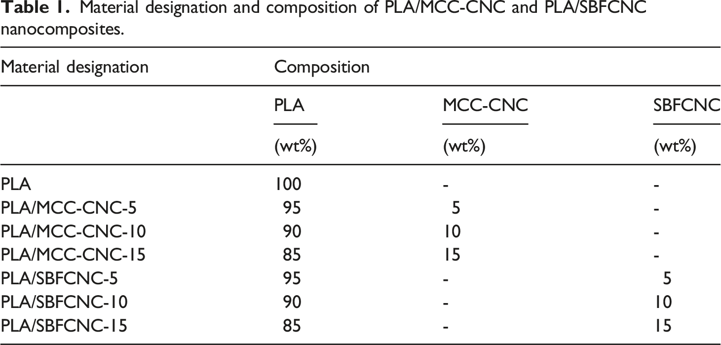
Material designation and composition of PLA/MCC-CNC and PLA/SBFCNC nanocomposites.
Morphology analysis
An Energy-Filtered Transmission Microscope (EFTEM, model: Libra 120-Carl Zeiss, USA) was used to study the morphology of MCC-CNC and SBFCNC. A droplet of MCC-CNC diluted with distilled water was deposited on a 400 square mesh copper grid and allowed to dry for 3 min. After drying, the specimens were negatively stained with 1% uranyl acetate (UO2(CH3COO)2) for 1 min and then examined by EFTEM. The same preparation method was repeated for SBFCNC samples. The aspect ratio of the samples was calculated and determined from the EFTEM image using ImageJ software.
Tensile test
The tensile test was performed on an Instron testing machine model 3366 (USA) at room temperature and 50% relative humidity, complying with ASTM D1708. The samples were cut into 30 x 5 mm rectangular shapes. The gauge length was set at 15 mm and the crosshead speed was 1 mm/min. Tensile strength, elongation at break, and tensile modulus were evaluated from the stress-strain curves. The testing was performed on at least five samples.
Zeta potential measurement
The Zeta potential of MCC-CNC and SBFCNC dispersions was measured using a dynamic light scattering (DLS) technique on a Zeta Potential Analyzer (Malvern Panalytical, model: Zetasizer Nano ZS, United Kingdom). The samples were sonicated for 5 min using a sonicator (QSonica, model: Q700, United Kingdom). Samples were then filled into zeta cells and the DLS measurement was performed at room temperature.
Fourier- Transform Infrared Spectroscopy
Fourier-Transform Infrared Spectroscopy (FTIR) of MCC-CNC and SBFCNC were recorded using an FTIR spectrometer (Perkin Elmer, USA) in the range of 550–4000 cm-1 with a resolution of 4 cm-1. The samples were dried in an oven at 60°C for 24 h prior to FTIR analysis.
Thermal properties characterization
Thermogravimetric analysis (TGA) was conducted using a thermogravimetric analyser (Perkin Elmer, model: Pyris 6, USA). The samples were heated from room temperature to 600°C at a heating rate of 10ºC/min in a nitrogen atmosphere. A differential scanning calorimeter (Mettler Toledo, model: differential scanning calorimetry [DSC] 200, USA) was used to evaluate the thermal behaviour of all nanocomposites. The specimens were scanned from 30°C to 190°C at a heating rate of 10 ºC/min and held for 1 min at 190°C. Then they were cooled from 190°C to 30°C at a cooling rate of 10 ºC/min and held for 1 min at 30°C. The glass transition temperature (Tg) and melting temperature (Tm) of the PLA nanocomposites were determined. The degree of crystanillity (χc) of PLA nanocomposites was calculated using equation (1):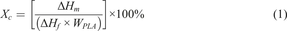
Ultraviolet-visible spectroscopy
Ultraviolet-visible (UV-Vis) spectroscopy (Agilent Technologies, model: Varian Cary 50, USA) was used to measure the light transmittance of PLA nanocomposites. The average thickness of the films (PLA/MCC-CNC and PLA/SBFCNC) is 20 µm. The scan range was set from 190 to 700 nm. The scan rate of UV-Vis is 4800 nm/min. All the measurements were conducted at room temperature.
X-ray diffraction
The X-ray scattering pattern was measured at room temperature using the Bruker D8 Advance machine (Germany) with Cu K radiation (= 0.1546 nm), 30 kV voltage, and 10 mA current. The samples were scanned at a fixed step size of 0.030° with a step time of 33 s in the range of 5° to 40°. An X-ray diffraction (XRD) diffractogram (intensity against 2θ) was obtained from the analysis. The crystallinity index (CrI) value and crystal size of the MCC-CNC and SBFCNC were identified. CrI was calculated using equation (2):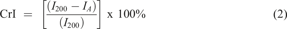
Results and discussion
Comparison of SBFCNC and MCC-CNC
Morphology analysis
Figure 1(a) and Figure 1(b) show the TEM images of MCC-CNC and SBFCNC, respectively. From Figure 1(a), MCC-CNC exhibited needle-like structure with length of 250 ± 50 nm and diameter of 10 ± 5 nm. From Figure 1(b), SBFCNC also showed similar needle-like structure with length of 585 ± 80 nm and diameter of 9 ± 3 nm. Acid hydrolysis using strong acids such as sulfuric acid is a harsh process. Both materials underwent an acid hydrolysis process where the amorphous region of the cellulose fiber was preferentially hydrolysed, leaving behind nano-sized rod-like particles.
23
TEM micrograph of (a) MCC-CNC and (b) SBFCNC.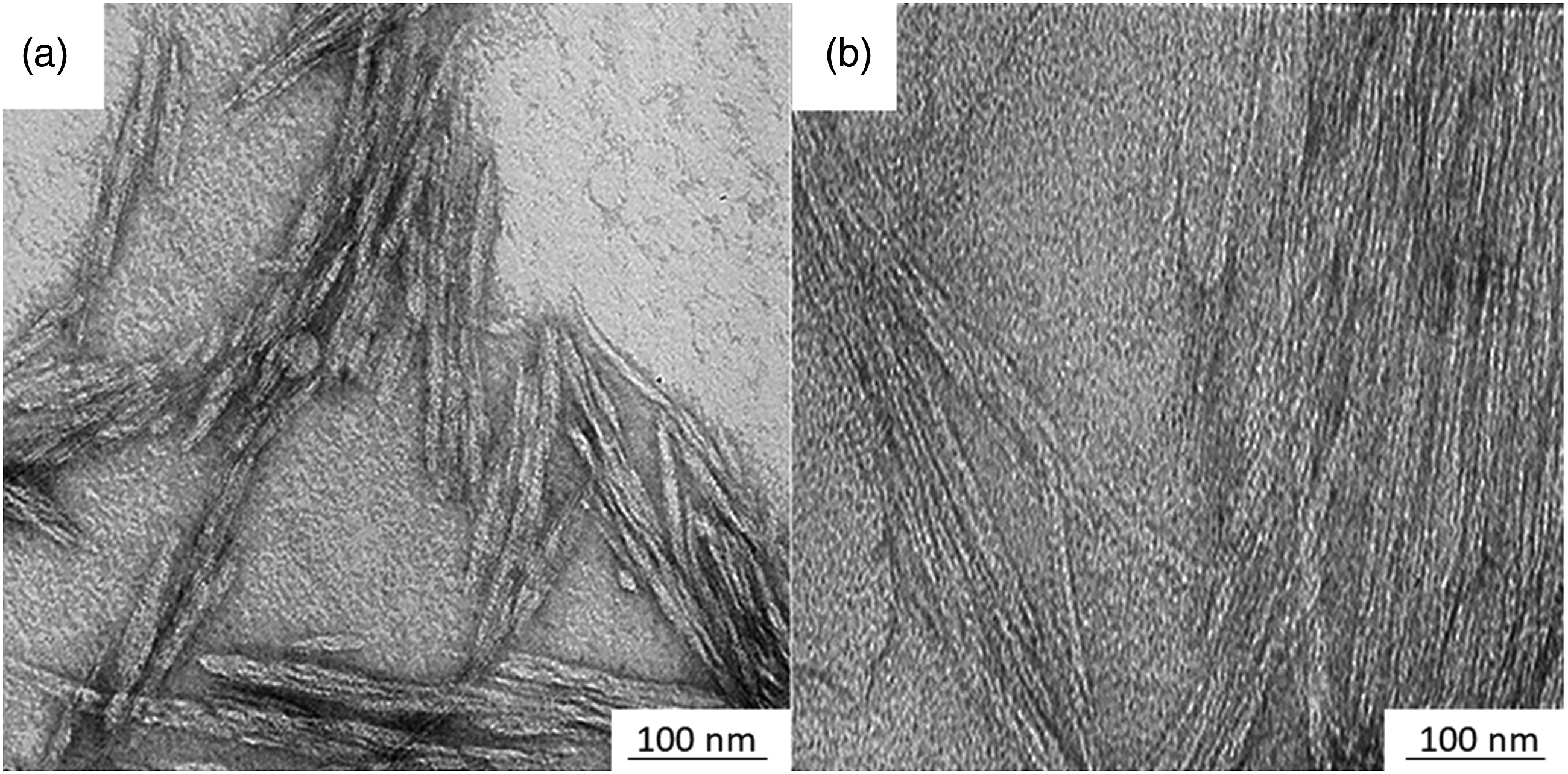
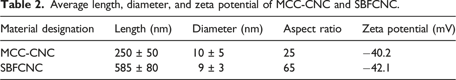
Average length, diameter, and zeta potential of MCC-CNC and SBFCNC.
Zeta potential measurement
The Zeta potential is an important method to determine the stability of CNC dispersion in aqueous solution. Table 2 summarizes the zeta potential measurements of MCC-CNC and SBFCNC. The zeta potential of MCC-CNC and SBFCNC showed a value of −40.2 mV and −42.1 mV, respectively. This indicates that each CNC contains negatively charged groups on its surfaces. Kargarzedah et al. 26 stated that negative zeta potential values were because of the presence of negatively charged groups on the surface. Recall that both MCC-CNC and SBF-CNC should contain negatively charged sulphate groups on their surface. Due to acid hydrolysis, CNC suspensions in neutral water will give negative zeta potential values. According to Oliveira et al., 27 by using sulfuric acid during the hydrolysis process, negatively charged sulphate groups are grafted onto CNC surfaces and the repulsive interparticle force helps to stabilize the colloidal suspensions. A large positive (+30 mV) or large negative (‒30 mV) zeta potential value indicates enough repulsive force for nanoparticles to form a stable suspension in water. 28 In this study, the Zeta potential of both MCC-CNC and SBFCNC was comparable. This is because both materials underwent the same hydrolysis under the same conditions. This indicates that SBFCNC can also form a stable suspension.
Fourier-transform infrared spectroscopy
Figure 2 shows the FTIR spectrum of MCC-CNC and SBFCNC. An FTIR spectrum can be used to determine the existence of cellulose in the samples. Based on the FTIR results, both samples displayed a broad band between the regions of 3200 and 3500 cm−1. The typical bands of cellulose, such as the –OH stretching vibration band and the –CH band, were present at 3338-3340 cm−1 and 2895-2900 cm−1.
29
The adsorption band observed in the region of 1647–1651 cm−1 is related to the OH-bending of adsorbed water.
17
Peaks in the region of 1429–1430 cm−1 are due to CH2 scissoring motion in cellulose.
30
Presence of small peaks at 1317 and 1318 cm−1 denotes CH2 wagging vibration of cellulose II. The absorption peak around 1160 cm−1 was associated with C-O-C asymmetric stretching in cellulose.
31
An intense peak around 1029-1030 cm−1 is an indication of sulphate groups present at the surface of both CNCs.
32
Peaks at 1105–1106 cm−1 and 898–899 cm−1 were associated with C-O-C pyranose ring stretching vibration (antisymmetric in phase ring) and β-glycosidic linkages between glucose units in cellulose, respectively.
17
FTIR spectrum of MCC-CNC and SBFCNC.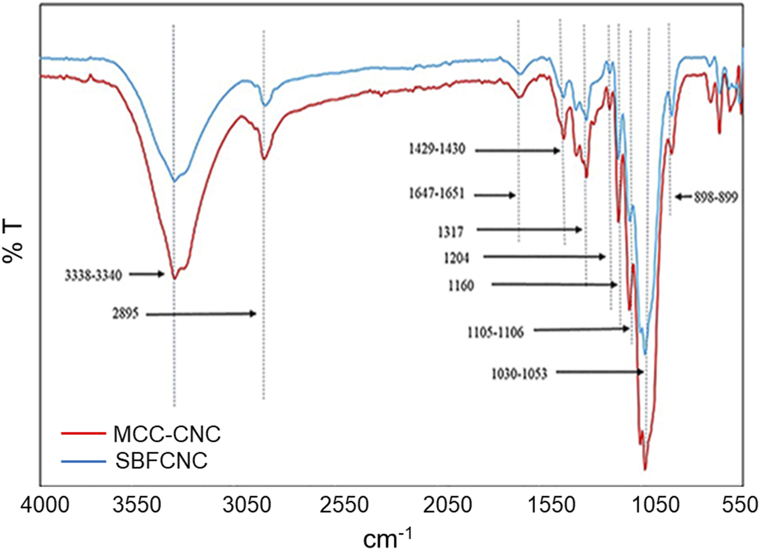
X-ray Diffraction
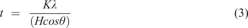
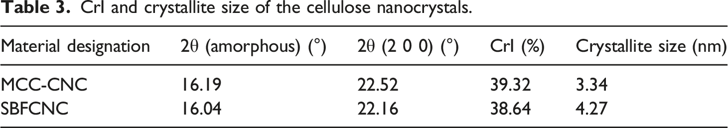
Figure 3 shows the X-ray diffraction pattern obtained for MCC-CNC and SBFCNC. Both MCC-CNC and SBFCNC display typical cellulose crystal structures with diffraction peaks at 2θ = 16° and 22°. Both values belong to (110) and (200) crystallographic planes which represent cellulose I structures (JCPDS No.03–0226).33,34 The diffraction peak 2θ = 22.16°, which is assigned to the crystallographic plane (200) could be identified as a sharp and narrow curve. This confirms the presence of a highly crystalline cellulose structure. Table 3 summarizes the calculated crystallinity index (CrI) and crystallite size of MCC-CNC and SBFCNC. The crystallinity index further confirmed the formation of crystalline material for both MCC-CNC and SBFCNC. The CrI of MCC-CNC was recorded at 39.32% and SBFCNC at 38.64%. The crystallite size of MCC-CNC and SBFCNC were calculated using Scherrer’s equation and recorded at 3.34 nm and 4.27 nm, respectively. The crystallite sizes of both materials did not differ much since they underwent the same acid hydrolysis treatment that can lead to crystalline cellulose structures. X-Ray diffraction patterns of MCC-CNC and SBFCNC. CrI and crystallite size of the cellulose nanocrystals.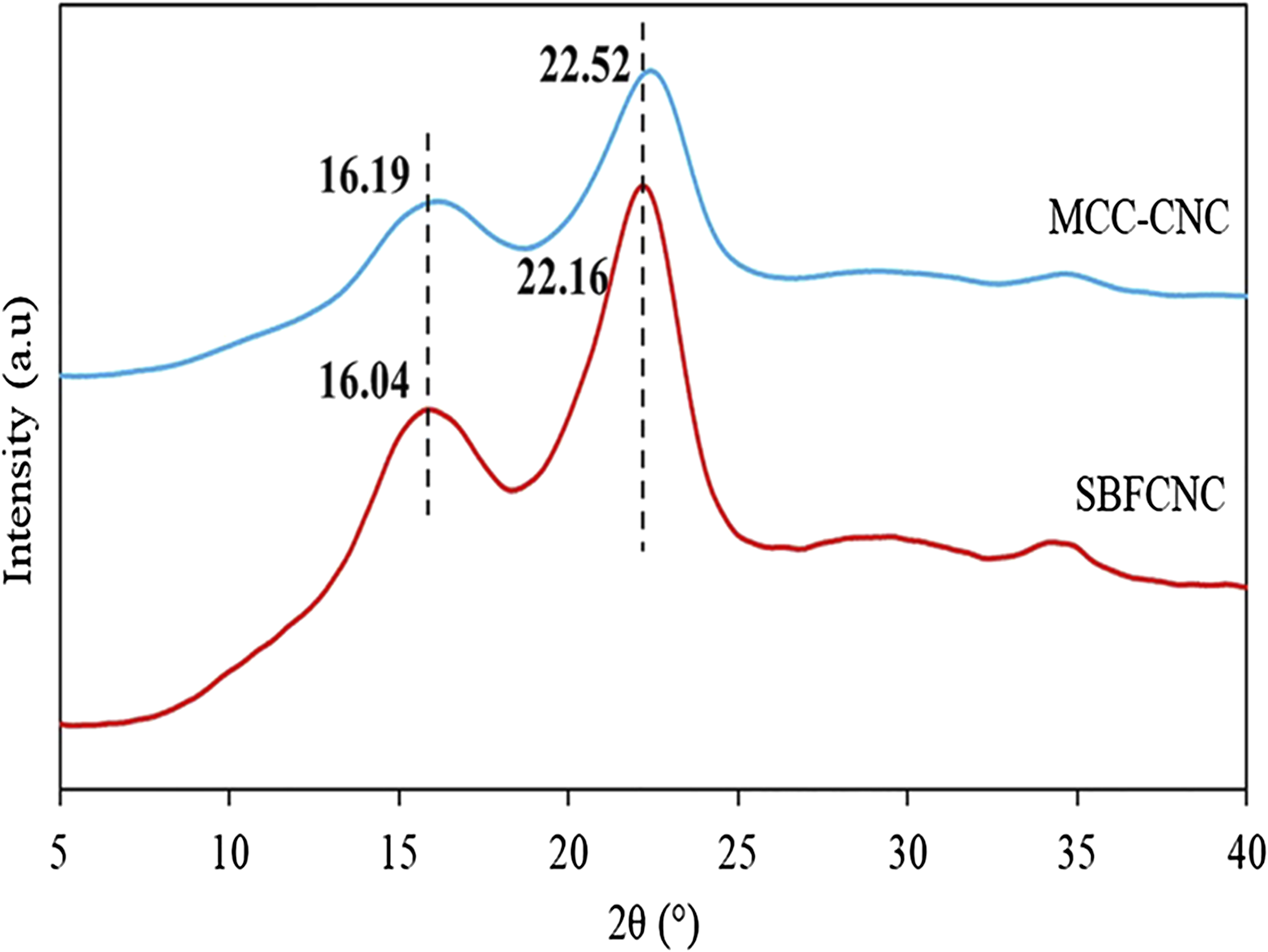
Characterization of PLA/MCC-CNC and PLA/SBFCNC nanocomposites
Thermogravimetric Analysis
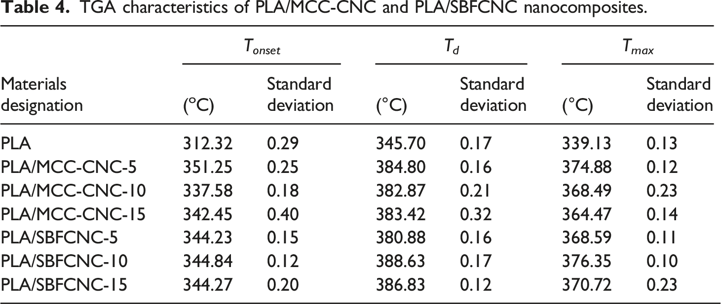
Figure 4(a) and (b), show the TGA and DTG curves of PLA, PLA/SBFCNC-5, PLA/SBFCNC-10, and PLA/SBFCNC-15 nanocomposites. The TGA curves of PLA/MCC-CNC nanocomposites are quite similar to those of PLA/SBF-CNC (figures not shown). The TGA results of the PLA/SBFCNC and PLA/MCC-CNC nanocomposites are summarized in Table 4. The T
onset
, T
d
, and T
max
of PLA were recorded at 312.32°C, 345.70°C, and 339.13°C, respectively, according to Table 4. When 5, 10, and 15% wt% SBFCNC were added, PLA T
onset
increased to 344.23°C, 344.84°C, and 344.27°C, respectively. Furthermore, increasing the amount of SBFCNC by 5, 10, and 15% wt% increased the PLA T
d
to 380.88°C, 388.63°C, and 386.83°C, respectively. Based on Figure 4, the Tmax of PLA/SBFCNC samples showed improvement compared to pure PLA. The Tmax for PLA/SBFCNC nanocomposites were 368.59°C (SBFCNC loading at 5 wt%), 376.35°C (SBFCNC loading at 10 wt%), and 370.72°C (SBFCNC loading at 15 wt%). The thermal properties improvement of the PLA could be associated with two factors: (1) the high thermal stability of the highly crystalline SBFCNC (as well as MCC-CNC) and (2) good interaction between the PLA and the cellulose nanocrystals. The highly crystalline CNC and its char formation provide heat barrier effects, hinder the release of volatile by-products, and thus increase the thermal stability of the PLA. Moreover, the interaction between PLA and SBFCNC ( or MCC-CNC), most likely intermolecular hydrogen bonding, could further enhance the thermal stability due to the fact that more thermal energy is needed for the bond dissociation and PLA decomposition.
35
(a) TGA and (b)DTG curves of PLA, PLA/SBFCNC-5, PLA/SBFCNC-10 and PLA/SBFCNC-15 nanocomposites. TGA characteristics of PLA/MCC-CNC and PLA/SBFCNC nanocomposites.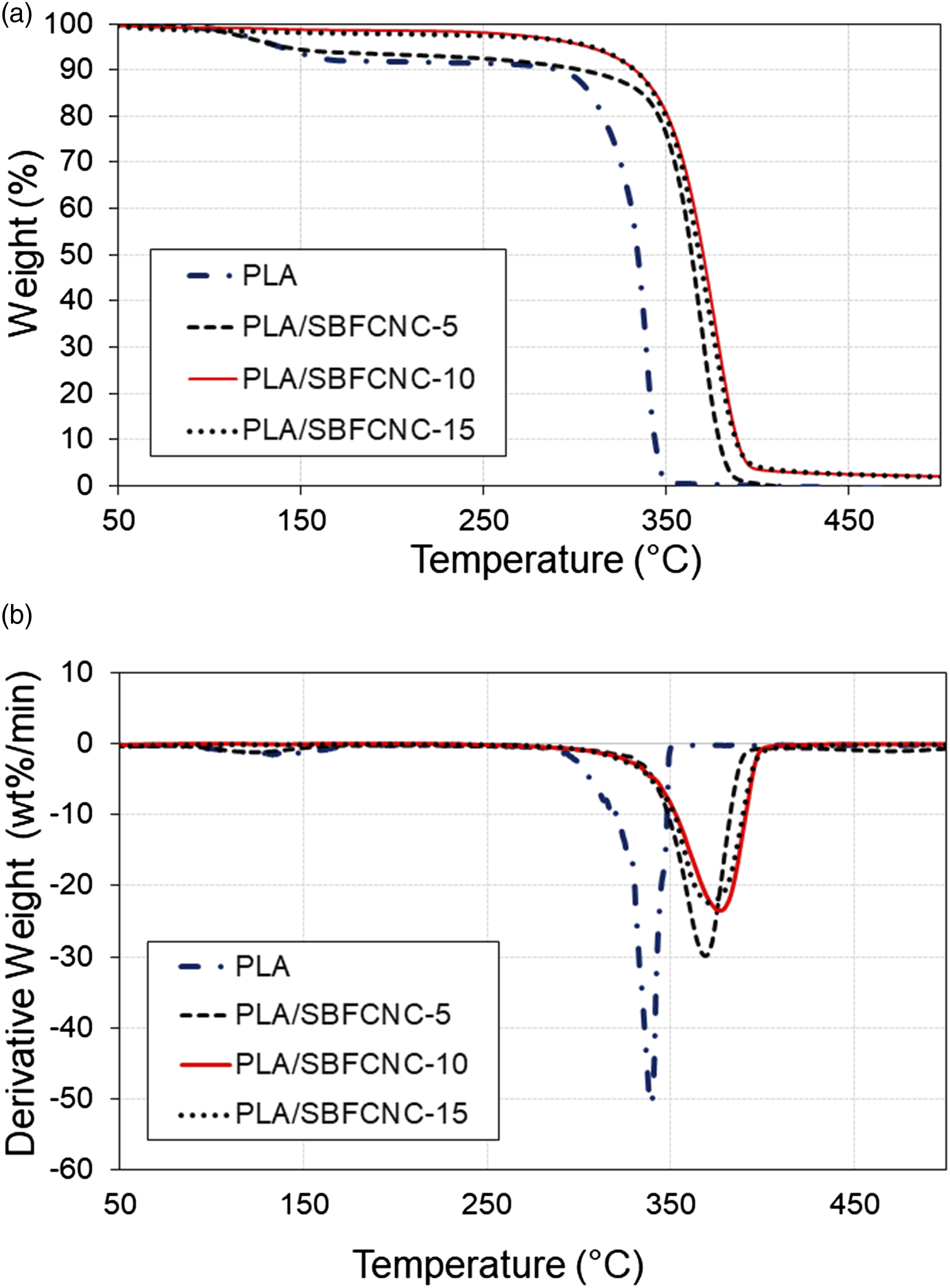
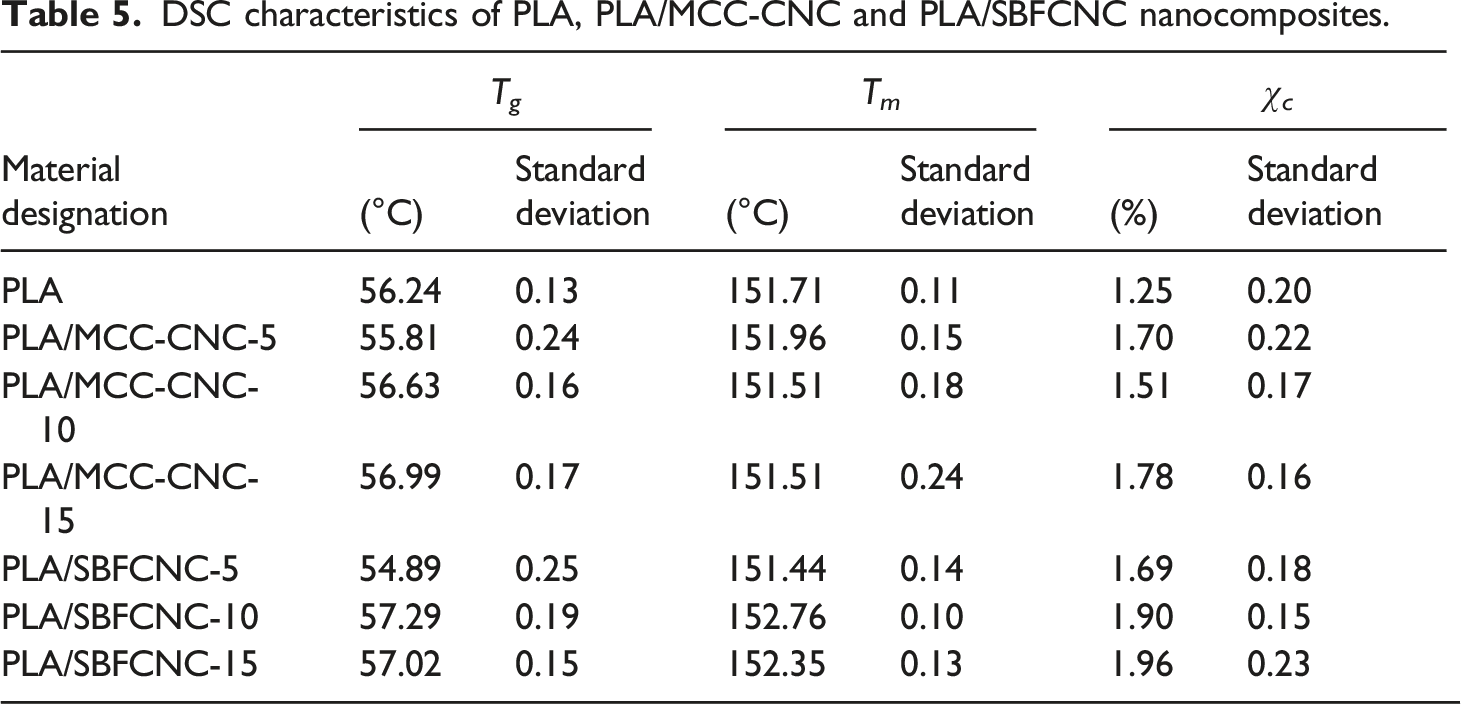
Differential Scanning Calorimetry
The effect of the incorporation of MCC-CNC and SBFCNC on the thermal properties of PLA was studied using DSC. The DSC thermograms of PLA/MCC-CNC and PLA/SBFCNC nanocomposites are shown in Figures 5(a) and (b). The glass transition temperature (Tg), melting temperature (Tm), and degree of crystallinity (Xc) obtained from the second heating scan are tabulated in Table 5. Based on Figure 5(a), the Tg and Tm of PLA were not affected much by the addition of cellulose nanocrystals. Poly (lactic acid) has Tg and Tm values of 56.24°C and 151.71°C, respectively. The low Xc of PLA and the PLA nanocomposites indicates that specimens prepared using solution casting are highly amorphous. In this study, the cold crystallization temperature (Tcc) of PLA and PLA/cellulose nanocrystals is not obvious. The incorporation of SBFCNC and MCC-CNC raised the Xc value of PLA. This suggests that the cellulose nanocrystals can act as nucleating agents.36,37 Both SBFCNC and MCC-CNC allow heterogeneous nucleation that reduces the free energy barrier and accelerates the crystallization of PLA. Sung et al.
38
obtained similar results when they used CNC from coffee silver skin to reinforce PLA. They found that when more CNC was added, the crystallinity increased due to nucleating effects induced by CNC in the PLA matrix. DSC thermograms of (a) PLA, PLA/MCC-CNC-5, PLA/MCC-CNC-10, PLA/MCC-CNC-15 nanocomposites and (b) PLA, PLA/SBFCNC-5, PLA/SBFCNC-10 and PLA/SBFCNC-15 nanocomposites. DSC characteristics of PLA, PLA/MCC-CNC and PLA/SBFCNC nanocomposites.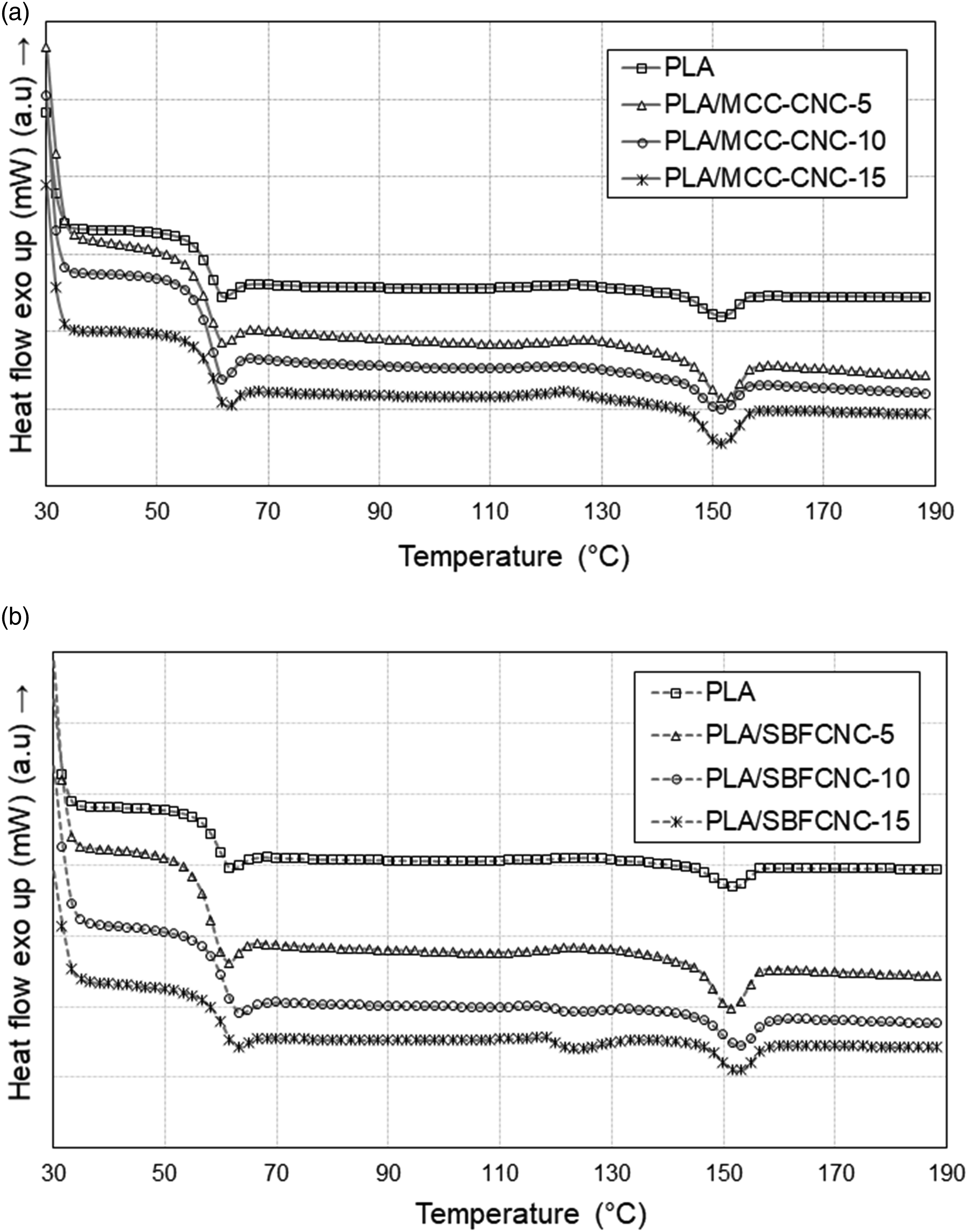
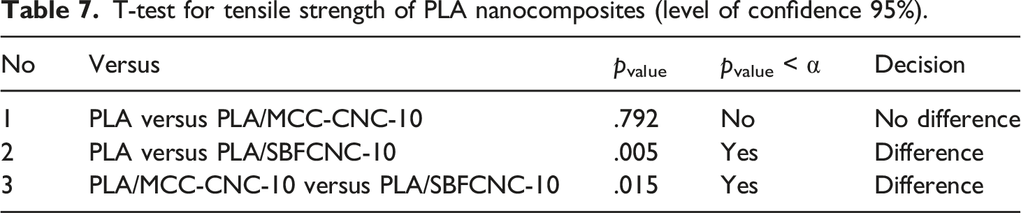
Tensile properties
Tensile properties of PLA, PLA/MCC-CNC-10 and PLA/SBFCNC-10 nanocomposites.
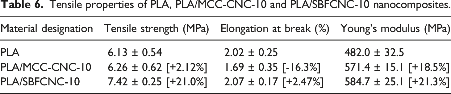
T-test for tensile strength of PLA nanocomposites (level of confidence 95%).
UV-Visible Spectroscopy
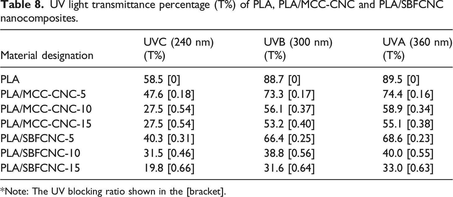
The transmittance spectra for PLA, PLA/MCC-CNC, and PLA/SBFCNC nanocomposite films are shown in Figure 6(a) and (b). The percentage of light transmittance of PLA nanocomposites at UV regions, i.e., UVA (360 nm), UVB (300 nm) and UVC (240 nm) was tabulated in Table 8. According to Figure 6(a), PLA has the highest transmittance percentage in the entire wavelength range of all samples, indicating the film’s high transparency. From Table 8, the transmittance of all PLA nanocomposites in the UVA, UVB, and UVC regions decreased gradually as the amount of MCC-CNC increased from 5 to 15 wt%. This can be attributed to the cellulose nanocrystals that act as barriers for light penetration and UV protection.
39
Similarly, Sirviö et al.
40
found that the transmittance (around 240 nm) of poly (vinyl alcohol) films containing 0.5 wt% and 10% wt% CNC was 54% and 12%, respectively. Although low transmittance percentage values were recorded, the authors explain that CNC can act as an efficient UV filler material, especially in the region of UVA and UVB that cannot be absorbed by the ozone layer. Figure 6(b) shows the transmittance spectra for PLA and PLA/SBFCNC nanocomposite films. PLA films have no UV blocking effects as they exhibit the highest transmittance percentage in the entire wavelength region. At 5 wt% of SBFCNC, the transmittance of PLA nanocomposites in the UVC, UVB, and UVA was recorded at 40.3, 66.4, and 68.6 %. When the SBFCNC content was increased to 10%, the percentage transmittances in the UVA, UVB, and UVC regions were 31.5, 38.8, and 40.0%, respectively. The values of transmittance in regions UVA, UVB, and UVC continue to reduce to 19.8, 31.6, and 33.0 when 15 wt% of SBFCNC is added. The reduction in transmittance indicates that SBFCNC can provide UV shielding for PLA films. In other words, the PLA/SBFCNC nanocomposites can absorb UV light due to their inherent properties of light scattering.
41
Yang et al.
42
also found that cellulose nanocrystals can increase the UV protection ability of cotton fabric. Moustafa et al.
8
also studied UV absorption properties and found similar results when they incorporated cumin oil and clay platelets into PBAT nanocomposites. In this study, the UV shielding ability of PLA/SBFCNC is better than that of PLA/MCC-CNC. The UV blocking ratio of PLA/SBFCNC-15 is in the range of 0.63–0.66 in the UVA, UVB, and UVC regions, which is higher compared to the PLA/MCC-CNC-15 (UV blocking ratio in the range of 0.38–0.54). This can be associated with the higher aspect ratio of the SBFCNC compared to the MCC-CNC. This again suggests that the CNC with a higher aspect ratio could give higher UV shielding for the polymer nanocomposites. Transmittance spectra of (a) PLA, PLA/MCC-CNC and (b) PLA/SBFCNC nanocomposites. UV light transmittance percentage (T%) of PLA, PLA/MCC-CNC and PLA/SBFCNC nanocomposites. *Note: The UV blocking ratio shown in the [bracket].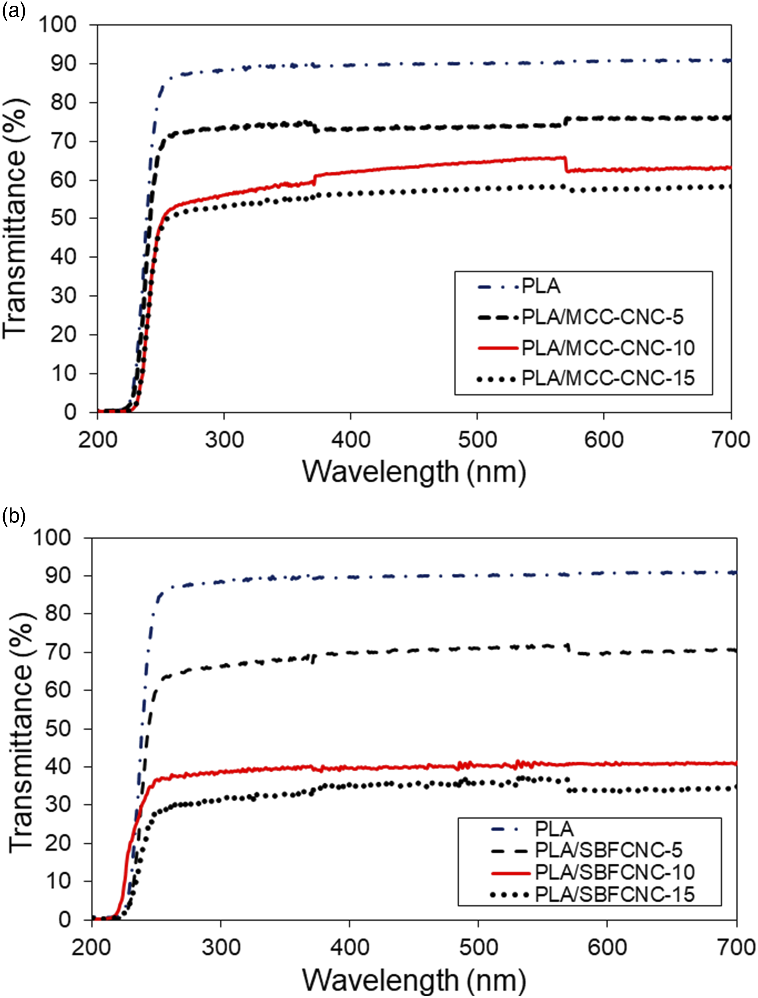
Conclusion
This study is devoted to investigating the feasibility of SBFCNC extracted from sugarcane bagasse to act as a nanofiller for biopolymers (e.g., PLA). The nano-structure and properties of the SBFCNC were compared with those of MCC-CNC (cellulose nanocrystals extracted from MCC). Both MCC-CNC and SBFCNC were successfully extracted using the sulfuric acid hydrolysis method from MCC and SBF. Although both MCC-CNC and SBFCNC exhibit stable suspension (zeta potential of −42.1 mV and −40.2 mV), the aspect ratio of SBFCNC (l/d approximately 65) is relatively higher than that of the MCC-CNC (1/d approximately 25). The tensile, thermal, and UV shielding properties of the PLA nanocomposites are influenced by the types of CNC. In this study, the performance of SBFCNC is higher than that of MCC-CNC in terms of tensile properties and UV shielding for the PLA bionanocomposites. Overall, SBFCNC is a potential bio-based nanofiller for the PLA. Further research work will be done on the biodegradability of the PLA/SBFCNC in order to make bionanocomposites for sustainable packaging applications.