
Abstract
Flax and polypropylene (PP) pultrudates of 4.76 mm in diameter were produced using a multi-die pultrusion system. The flax content was 50 vol.%. Pultrusion conditions were varied to produce four porosity content between 4% and 22%. The pultrudates were pelletized into lengths of 6 and 15 mm, and injection-molded with pure PP to reduce the part flax content to 25 wt.%. Results showed that well consolidated pultrudates, having porosities up to 8%, were more resilient to the pelletizing process such that the pellets remained structurally intact after the process. These pellets went smoothly through the hopper into the injection molding machine screw. Pellets with void content higher than 8% lost integrity during pelletizing leading to uniform mixing. Exposed fibers segregated from the polymer in the hopper leading to ununiform mixing. The highest mechanical properties improvement compared to pure PP was using 15 mm pellets that had a prorosity of 8%. The tensile modulus doubled at 4652 ± 113 MPa. The impact strength increased by almost five times at 10.5 ± 0.7
Introduction
Inorganic fibers and fillers such as glass fibers, talc and mica are widely used to reinforce the thermoplastic polymers in the automotive industry. 1 Yet, the production and disposal of such materials have an adverse impact on the environment. Due to rising environmental awareness, new environmental laws and regulations were introduced to help reduce the inorganic waste problem. 2 These new environmental laws and regulations are putting great pressure on the automotive industry to replace some of these inorganic fillers with biodegradable alternatives. In fact, the U.S Department of Energy’s Vehicle Technologies Office (VTO) introduced a multidimensional program to promote automotive Lightweight Materials (LM) to ensure energy security through renewables. VTO argued that the replacement of glass fibers with natural fibers will allow lighter parts to be used while increasing the percentage of renewables within the vehicle. 3 It is estimated that a 10% weight reduction could reduce fuel consumption by 6–8% 4 since lighter objects need less energy to get transported compared to heavier ones. Therefore, lighter materials provide an opportunity to improve vehicle fuel economy and mitigate greenhouse gas (GHG) emissions. In response, many auto-makers are increasing the use of natural fiber-reinforced composites. For example, Audi uses natural fiber-reinforced composites to produce boot liners, hat racks, seat backs, back door panels and spare tire-linings for their new cars. Like the automotive industry, many other industries such as medical and pharmaceutical, protective clothing, food packaging and hygiene clothing are finding more ways to utilize natural fiber reinforced composites for both structural and non-structural applications. 5 For example, Bcomp ltd. produces winter and summer sports equipment using only natural fiber-reinforced composites. GAF materials corp. uses natural fiber-reinforced PP to make composite deckings.5,6
Flax fibers are becoming more popular in industrial applications due to their low environmental impact and light weight. In comparison to other natural fibers, flax fibers can be processed at higher temperatures due to its high cellulose content. 7 Natural fiber thermal degradation normally occurs when cellulose is exposed to a temperature range above 200°C. Lignin, on the other hand, starts to degrade when the temperature approaches 160°C. Flax fibers are made of low lignin content (2%) and comparatively high cellulose content (64%). 8 This makes flax more resistive to thermal degradation compared to other natural fibers. In addition, flax is also preferred due to its higher tensile properties, which can be attributed to the high cellulose content as well. Flax fibers have the highest Young’s modulus values amongst natural fibers, comparable to e-glass fibers. 9 Therefore, flax-reinforced composites are a great choice for sustainable industrial applications.
There is normally a very limited interaction between hydrophilic fibers such as flax fibers and hydrophobic matrices such as PP resulting in a reduced interfacial strength as well as increased moisture absorption. Different kinds of treatment can be used to improve the interaction including physical and chemical treatments.10,11 Of all chemical methods to improve the interaction in natural fiber composite, maleic anhydride polypropylene (MAPP) is recognized to be the most popular treatment. It has been proven to yield twice the strength as achieved when used with silane treatment. 12
Thermoplastic polymers have a very high melt viscosity compared to thermoset polymers. This high viscosity makes it very difficult to impregnate fibers and mold the final part in a one-step process. 13 Thus, an intermediate form, in the form of bulk charge or pre-impregnated pellets, is introduced prior to the final part production which is normally done using compression or injection molding process. Fibre-reinforced thermoplastic composite materials are often categorized based on their fiber reinforcement lengths. For instance, long fibre-reinforced thermoplastics (LFT) are composite materials consisting of thermoplastic polymer and discontinuous reinforcement fibres whose length-to-diameter aspect ratio is larger than the critical aspect ratio above which fiber rupture is favored over fiber/matrix debonding. 13 LFT offers superior mechanical properties compared to short fibre-reinforced thermoplastics (SFT). LFT production has experienced fast growth in the last two decades. A market survey published in January 2017 projected that the LFT global market value will grow from USD 3.28 billion to USD 5.55 billion by 2022. 13 Several thermoplastic polymers were utilized as LFT polymers including PP,14,15 Polyamide 9 (PA6), 16 Polylactic acid (PLA), 17 Polymethylmethacrylate (PMMA), 18 and high density polyethylene (HDPE). 19
The desire to reduce processing steps and shipping costs for LFT intermediate form resulted in the implementation of Direct LFT (D-LFT) in the 90’s.13,20 D-LFT works by combining the injection or compression molding station with an inline-compounding of fibers and polymers.21,22 The polymer is fed into an extruder, often a twin screw extruder, where it is melted and mixed with fillers, pigments and additives in order to achieve a homogeneous molten mixture. It is then mixed with continuous fiber reinforcement strands. Glass fibers are typically used as reinforcements for such applications. This material is then extruded and cut into a charge, and then transferred to a cold mold where it is compressed into the desired size of the final component. 23 The polymer only passes through a single melt history. This minimizes thermal degradation and improves mechanical properties. 24 Additionally, this process can be used to produce both SFT and LFT. 25 Another LFT manufacturing technique is referred to as the direct strand deposition. 26 The direct strand deposition was developed to produce LFT charges that are placed into the mold for compression molding but using a single-screw extruder. However, this process completely depends on the single-screw plasticisation for both fiber dispersion and impregnation. Ren et al. 27 faced impregnation challenges when they directly mixed the dry fibers with PP in a single screw-extruder. They tested the effect of changing the fiber weight fraction from 10 to 40% on impregnation and dispersion levels. They observed that fiber length and dispersion decreased as fiber content increased. Fiber-to-fiber interactions were thought to increase with adding fiber content. Low impregnation was also observed at higher fiber content, and it was recommended to reduce the fiber weight fraction.
The adoption of the D-LFT process is costly. It was estimated that the adoption cost can be offset once the annual production volume is increased to 30,000 units and above. 28 In addition, the D-LFT process can be complicated to implement since it forces the part manufacturer to handle purchasing the dry fibers and the polymer at the same time. Offering ready-to-use LFT pellets gives part manufacturers the flexibility to choose the process that they wish to implement. It simply allows them to place the LFT pellets in the hopper for injection or bulk molding compound.
The second intermediate form, pellets, can be used to make SFT and LFT. SFT pellets are usually produced by extrusion compounding using short chopped fibers that are introduced into the extruder together along with the polymer. Commonly, 4 mm-long chopped fibers are used, and the fiber length is subsequently shortened to less than 0.5 mm in the pellet while passing through the extrusion screw. 29 Thus, due to the limitation of short fibers, SFT pellets add inadequate reinforcing capabilities to the final composite material. On the other hand, using LFT pellets was proven to improve impact/stiffness as well as creep, fatigue and high temperature properties. 30 LFT pellets are often produced using the thermoplastic composites (TPC) pultrusion process. During the TPC pultrusion process, yarn precursors which contain the polymer and reinforcement fibers are wound into bobbins that are placed in a creel. The polymer and reinforcement fibers are then pulled together through a number of dies that are heated to liquefy the polymer fibers. In order to fully impregnate the reinforcement fibers, the yarns that enter the dies contain an excess of polymer fibers. This excess polymer, consequently, creates a backflow which helps raise the impregnation pressure.31–34 This technique does not damage the reinforcing fibers and the fibers typically remain quasi-continuous after they have been processed. The pultrudates are then set to cool off and are cut into pellets of desired length. The LFT fiber length is determined by the cut length of the pellets.
Vaidya et al. 35 produced 12 mm Glass/PP LFT pellets using a TPC pultrusion process. These pellets were blended with inorganic pigment-colored compound pellets in order to study the processing and performance of inorganic-pigmented colored LFT in comparison with unpigmented LFT. Their work proved that LFT can be colored with inorganic pigments and still retain good mechanical properties. Batrus et al. 36 designed and fabricated E-glass/PP LFT bus seat using extrusion-compression molding. The LFT pellets were produced using a TPC pultrusion process. The LFT seat design acheived 43% weight savings and 18% total production cost savings over typical seats that contain a circumferential steel frame. Yet, these two research papers did not specify the pellets’ void contents nor analyze the impact of LFT pellets’ void contents on the mechanical properties of the final injected part. The TPC pultrusion conditions such as pulling speeds, die geometry and set temperatures were not reported. Furthermore, inorganic reinforcement fibers were used in both studies.
Hartness et al. 37 produced Glass/PP LFT pellets using a TPC pultrusion process. The glass contents in the LFT pellets were varied between 10 and 70% by weight. It was observed that the TPC pultrusion process led to a high level of impregnation although the LFT pellets’ void contents were not specified in their research. Several other researchers have implemented TPC pultrusion to produce LFT pellets as well. It was observed that the fibers attained high levels of impregnation with PP polymer using TPC pultrusion.38–40 Additionally, LFT pellets can also be produced by similar processes such as wire coating, 41 solid state polymerization 42 and commingling. 43
Achieving low void contents in the pultrudates at relatively high pulling speeds using TPC pultrusion can be challenging as there seems to be a trade-off between increasing the pulling speed and decreasing the void contents due to the high melt viscosities of the thermoplastic polymers. 44 In fact, Lapointe et al. 44 observed a significant increase in void contents in C/PEEK pultrudates when the TPC pultrusion speed was increased from 50 to 100 mm/min. The void contents increased by over 85%. Wiedmer et al. 45 pultruded Carbon/Polymide-12 (C/PA-12) hybrid yarn using different pulling speeds. The void content tripled when the pulling speed increased from 100 to 400 mm/minute. Ghaedsharaf et al. 46 pultruded Carbon/Polyetherimide (C/PEI) biaxial braid which was made of commingled yarns. The void content significantly increased when the pulling speed was raised from 50 to 150 mm/minute. They hinted that the reason for the void increase was possibly due to the polymer flow time which became too short to fully penetrate the carbon fiber bundles when the pulling speed was raised to 150 mm/minute. Thus, all these findings indicated that increasing pulling speed, while keeping the same pultrusion tooling geometry, could lead to a significant increase in the void content.
There are very few published papers that studied the effect of intermediate forms on the performance of the end part of the Flax/PP composites.47–49 Barkoula et al. 49 studied Flax/PP SFT and LFT pellets to be used for injection molding. They compared the reinforcing capabilities for both the SFT and LFT pellets using impact and tensile tests. Producing the Flax/PP pellets was done by an extruder for SFT pellets and by TPC pultrusion for the LFT pellets. They observed that the LFT pellets resulted in a significantly higher impact strength in the injection-molded parts. Yet, Barkoula et al. 49 did not discuss the influence of the LFT pellets’ void contents on the manufacturability of injection molded parts.
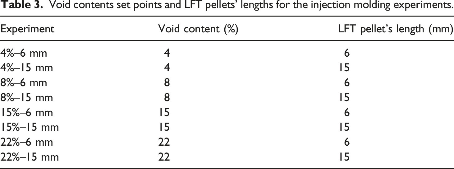
Having a low void content requirement in LFT pellets may restrict the pulling speed of TPC pultrusion which may lead to limiting the use of LFT pellets in industrial applications. Thus, it is crucial to quantify the LFT pellets’ void content that does not jeopardize the mechanical properties of the injected final parts. On the other hand, low void contents in the pultrudates may result in LFT pellets being structurally intact. In a previous study, Flax/PP LFT pellets having low void contents using TPC pultrusion were produced. 15 The low-void LFT pellets were able to remain structurally intact during the pelletizing process and experienced a smooth injection molding process. However, the investigation was limited to well impregnated LFT pellets. To better understand the influence of the LFT pellets’ void contents in injected molded parts, we produced pultrudates using four different void contents. These pultrudates were pelletized into two different lengths, 6 mm and 15 mm. The LFT pellets were then added, with pure PP pellets, into a master mixture before being added to the injection molding hopper to produce injection molded parts. Finally, the injected molded parts were characterized by tensile and Charpy impact tests to evaluate the mechanical strength. In the injection molded specimens, the fiber/polymer impregnation was characterized using scanning electron microscopy (SEM).
Experimental
Materials
Pure PP (Guangzhou Chemical Fiber Co.) in the fiber form (finess of 100 tex) and in the pellet form were used for the pultrusion and injection molding. The melting point of the PP was 166.5
Flax thermal characterization
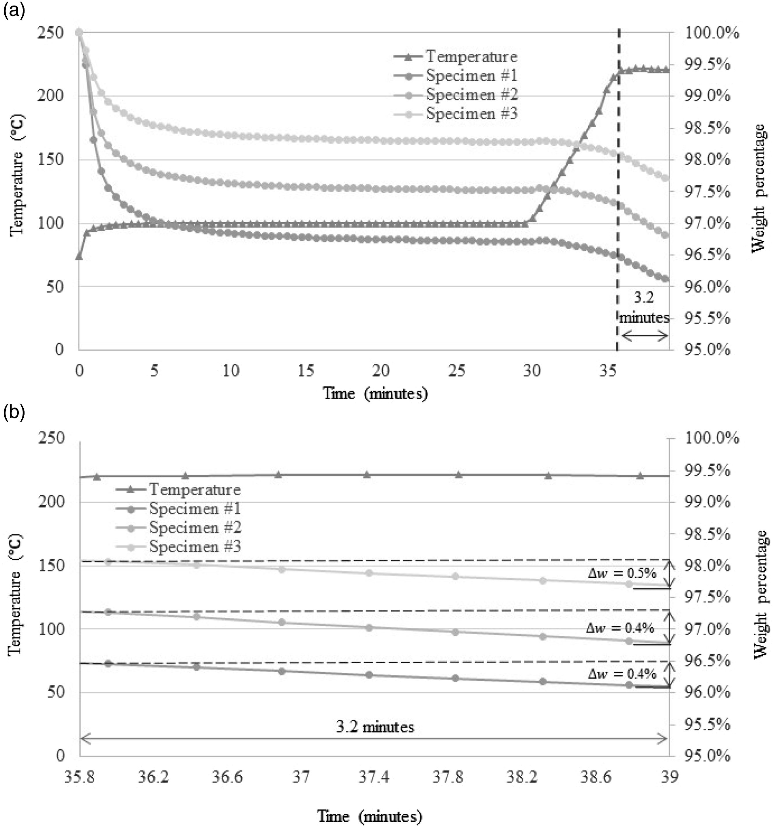
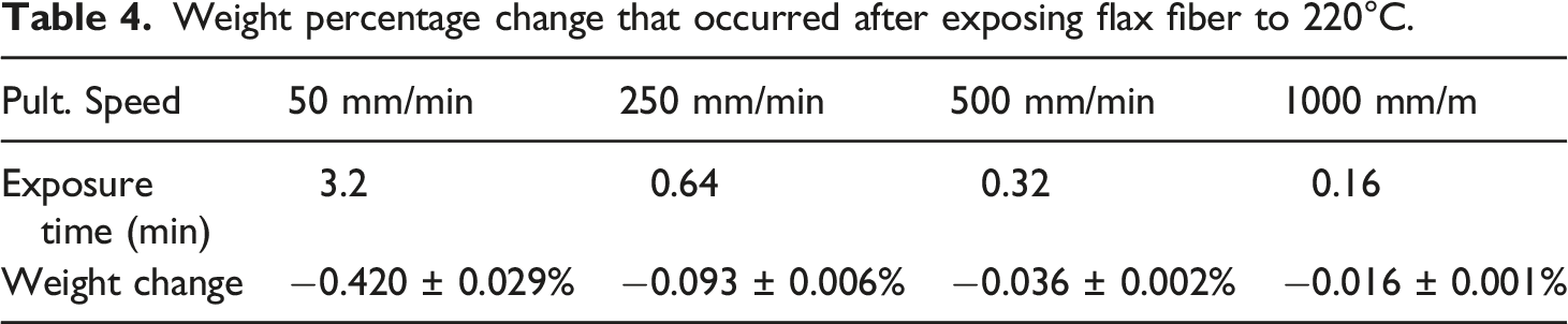
Thermogravimetric analyses (TGA) of flax fibers were conducted (Q50, TA Instruments) with a temperature ramp-up of 2°C/min until 300°C under air atmosphere (40 mL/minute). However, during the TPC experiments, the total residence time at the processing temperature of 220°C is dependent of pultrusion speed. At low speed (50 mm/minute), flax fibers spent 3.2 min inside the heating dies. While at the 250, 500 and 1000 mm/minute pultrusion experiments, flax fibers spent 0.64, 0.32 and 0.16 min respectively. To better quantify the flax degradation during the TPC pultrusion at different pultrusion speeds, TGA of flax fibers was conducted by reproducing the thermal conditions during the pultrusion experiments. Three flax samples of approximately 1g were dried for 48 h at 60°C before the TGA tests. All TGA experiments featured 40 mL/minute air flow. First, the flax fibers were exposed to 100°C to reproduce the preheating stage, followed by a thermal ramp at a 20 °C/minute to 220°C to reach the pultrusion dies’ temperature. Finally, the flax sample was exposed to an isothermal environment for 3.2 min, the same duration as the travel time in the pultrusion dies at 50 mm/min.
Pultrusion apparatus
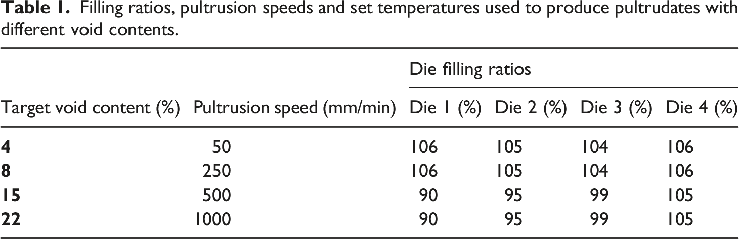
Figure 1(a) presents the schematic for the pultrusion system used in this study. The pultrusion apparatus contained a creel, a guide, a preheater, four heating dies, a cooling die, and a pulling system. The creel allowed for individual tension adjustment for each of the bobbins. The tension was set at 1 N per bobbin holding the reinforcement fibers. No tension was applied to the bobbins that were holding the polymer fibers. The preheater was a metallic tube, 300 mm-long and 16.2 mm in diameter, wrapped with a strip heater. Figure 1(b) and (c) present detailed dimensional description of the system. The final diameter decreases from die 1 to 4. All four heating dies had a 31.75 mm conical cavity tapered at (a) Schematic of the multi-die pultrusion system used in this study. The pultrusion system includes a creel, a pre-heater, four pultrusion dies, a thin-walled tube, a cooling die, a puller and a cutting saw (not shown). (b) & (c) dimensions of the system. The final diamter decreases from die 1 to 4 while the tapered angle of the die was constant in all dies at 10°. Filling ratios, pultrusion speeds and set temperatures used to produce pultrudates with different void contents.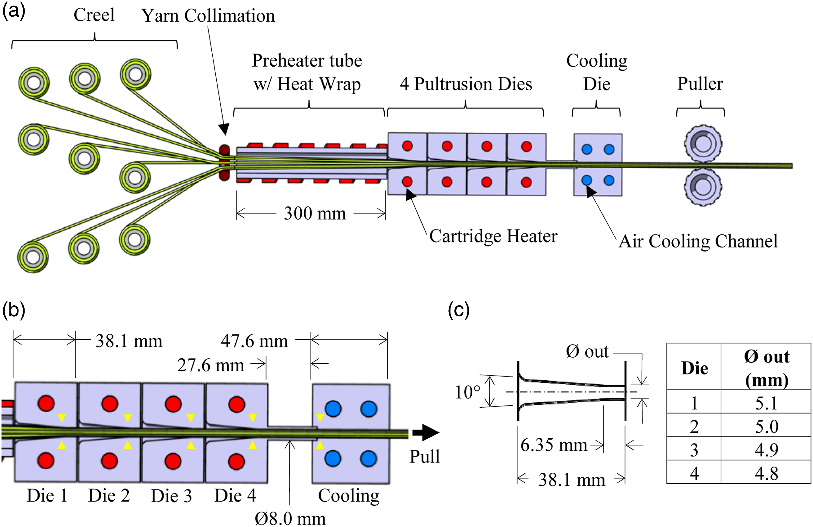
Morphological characterization
The pultruded rods impregnation morphology was characterized by a microscopic observation of the cross-section. An injected coupon was polished and then analyzed using a digital microscope; (Keyence, VHX 7000). Full ring was selected for lighting type. Photos of 150 and 300 X magnification were taken of the injected coupon. Void content was measured according to ASTM2734-09 Method C. The fracture surfaces of specimens were examined in a SEM (TM300, Hitachi).
Injection molding
After production, Flax/PP pultrudates were cut into 6 and 15 mm long pellets using a manual paper trimmer (Model #118, Dahle). The LFT pellets were oven-dried for 24 h at 60
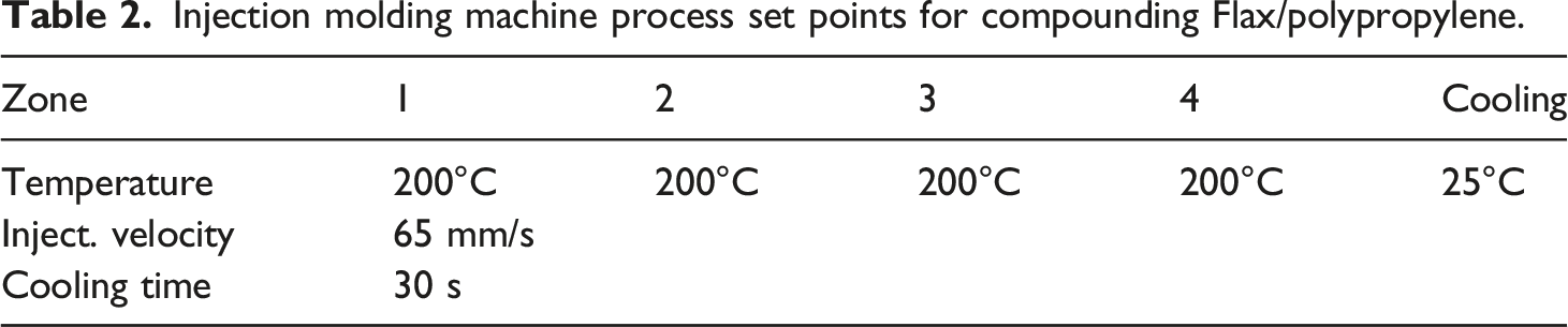
Injection molding machine process set points for compounding Flax/polypropylene.
Void contents set points and LFT pellets’ lengths for the injection molding experiments.
Mechanical Characterization
Tensile tests were performed according to ASTM D638-44 in a universal testing machine (Model, Brand). The size of the tensile specimen was 165 x 13 x 19 mm according to ASTM D638. The Charpy impact test specimens were tested according to ASTM D6100.
Results and discussions
Thermogravimetric analysis of the flax fiber
Figure 2 shows a typical TGA plot of flax fibres during a temperature ramp-up at 2°C/min under air atmosphere. This figure shows the flax mass loss and mass rate of change with respect to temperature. As the temperature rises, and before reaching 200°C, the flax mass decreases slightly due to water evaporation. Beyond 200°C, the flax weight continues to decrease at a much higher rate. Results from this test are consistent with previous TGA of flax fibre found in literature 50,51: as thermal degradation is triggered above 200°C, mass loss starts to increase. This finding implies that the thermal degradation during the pultrusion experiments happens inside the heating die at which the flax is exposed to a temperature above 200°C. To verify if substantial degradation could occur in the time span of manufacturing, TGA experiments were conducted. The TGA experiments resembled the thermal conditions for all pultrusion experiments. Figure 3(a) shows the temperature evolution and mass loss monitored using flax fibre weight percentage. Three samples were used to reproduce flax thermal history in the pultrusion heating die. In the first 30 min, the temperature was set at 100 Thermogravimetric analyses of the flax fiber at what rate and what air flow. The thermal degradation started at 200°C (a) Thermogravimetric analyses of flax fiber. Three samples were used to reproduce flax thermal history in the pultrusion heating die. (b) The last 3.2 min of the TGA expierment. This time interval corrosponds to the time that flax fiber spent inside the heating dies during pultrusion at 50 mm/minute. Weight percentage change that occurred after exposing flax fiber to 220°C.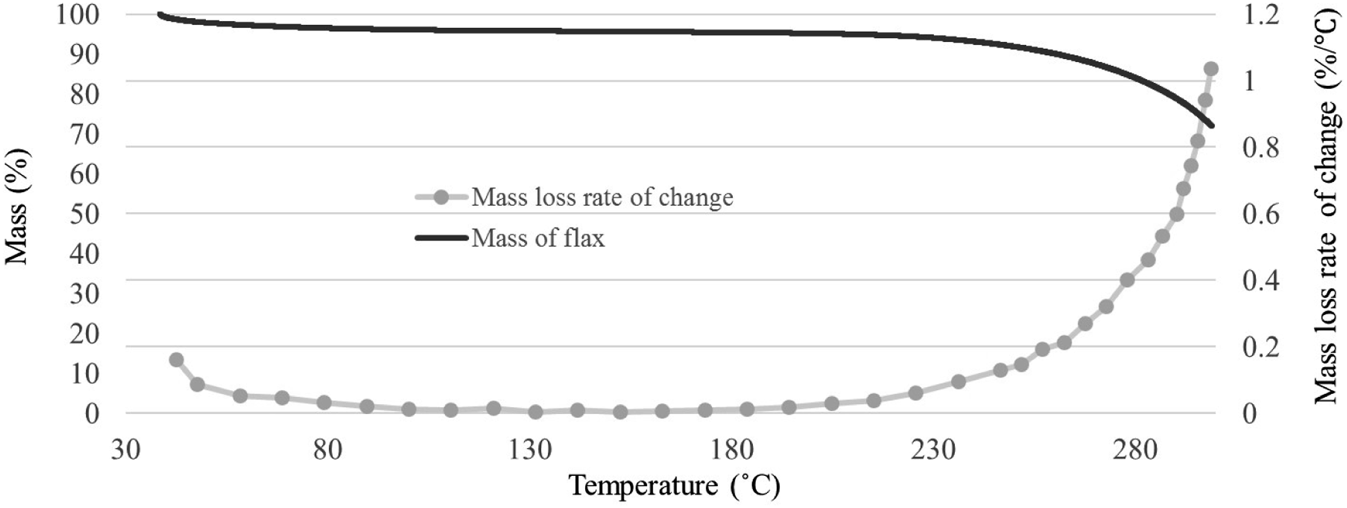
Pultrudate consolidation
The pultrusion of Flax/PP experiments were conducted without any fiber breakage event. Figure 4 shows cross sections with respect to the pultrusion process speed. Figure 4(a) and (b) show cross-section images of LFT pellets produced at 50 and 250 mm/minute respectively. The cross-section images show round shapes with very few voids. The edges do not look damaged and the polymer had fully melted during the pultrusion process. Additionally, the two top insets show that the polymer fibers located at the center of the rod fully melted during the pultrusion process and impregnated the flax fiber even at the centre, which is the last place in the pultrudate to melt. Microscopoc image for pultruded rods produced at: (a) 50 mm/minute. (b) 250 mm/minute. (c) 500 mm/minute. (d) 1000 mm/minute. Pultruded rods produced at 500 mm/minute and above had un-melted PP fibers since the processing tempeture did not reach the core of the pultrudates at the heating dies. The scale bars in all images follow the same format as in (a).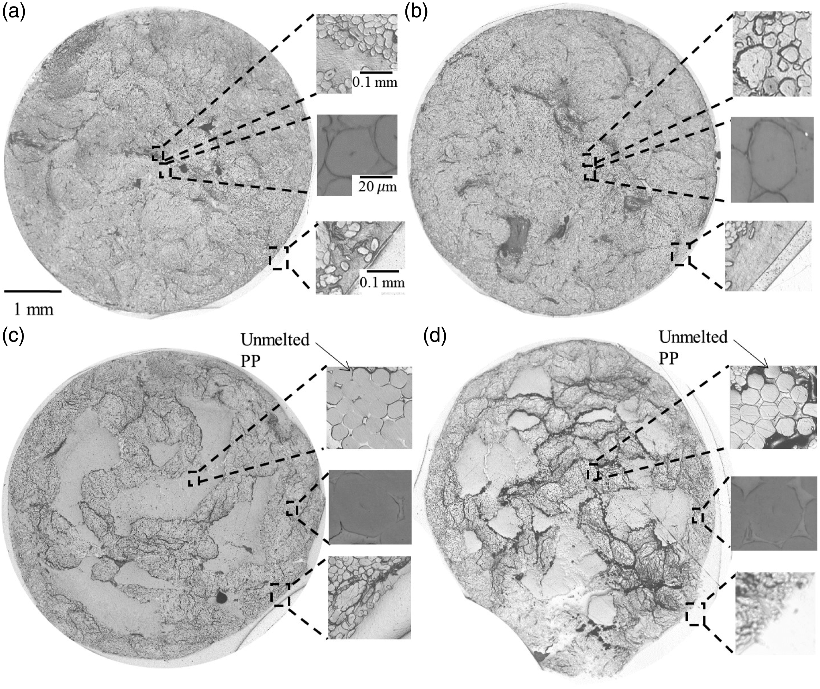
Figure 4(c) shows a cross-section image of LFT pellets produced at 500 mm/minute. The cross-section image shows less of a round shape with some voids. Additionally, the inset shows that the polymer fibers located at the center of the rod did not fully melt during the pultrusion process. However, the middle inset shows one flax fiber inside an area which seems to be fully impregnated near the outer surface. This finding was expected since the outer surface is heated first during pultrusion. Figure 4(d) shows a cross-section image of LFT pellets produced at 1000 mm/minute. The cross-section image shows an arbitrary shape with a significant amount of void. Additionally, the polymer did not fully melt during the pultrusion process. The arbitrary shape is attributed to the lack of flax fiber wetting by the PP polymer. Poor load transfer between the two phases resulted in a deconsolidation state and difficulty to retain the circular shape. Moreover, similarly to the LFT pellets produced at 500 mm/minute, the middle-enlarged view close to the rod edge also shows a flax fiber inside an area where there seems to be full impregnation near the outer surface. Obviously, increasing the pulling speed results in a reduction of the exposure duration at elevated temperatures. The cross-section images in Figure 4 clearly indicate that this short exposure duration reduces the time that the polymer is in a melted stated and able to flow. For 500 mm/min and 1000 mm/min, that exposure was not long enough to melt the polymer at the center of the pultrudate.
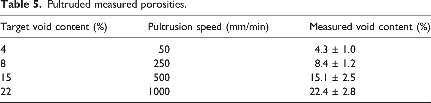
Pultruded measured porosities.
Pelletizing quality
These pultrudates were then cut into two different lengths; 6 and 15 mm. Figure 5 shows the appearance of LFT pellets cut at 6 and 15 mm for the four void contents, i.e. 4%, 8%, 15% and 22%. The top four images represent the 6 mm LFT pellets and the lower four images represent the 15 mm LFT pellets. Figure 5(a) and (b) represent the LFT pellets with the lowest void content which was measured to be 4.3 LFT pellets obtained with two different lengths (6 mm and 15 mm) and four different void contents. The top four images represent the 6 mm LFT pellets and the lower four images represent the 15 m LFT pellets. (a) & (b) 4%, (c) & (d) %8, (e) & (f) 15% and (g) & (h) 22% void content. Pelletizing pultrudates with void contents above 8% seems to result in cracked and opened pellets.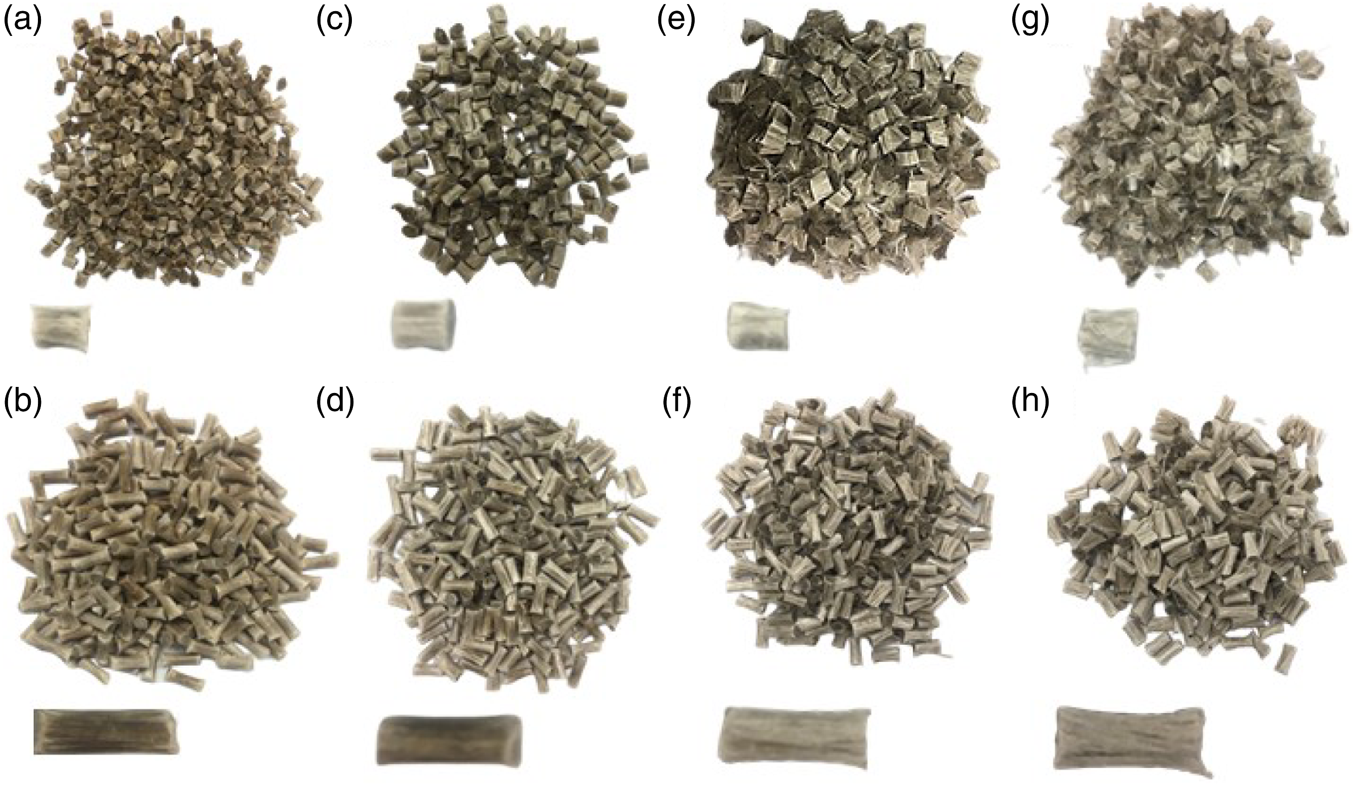
Observation of the manufacturability of the injection process
During injection molding, the LFT pellets with void content of 4% and 8% went smoothly through the hopper and the screw of the injection molding machine without any manual intervention as seen in a supplementary video, which can be viewed at https://youtu.be/0kOILBqbq0U. The remaining LFT pellets with higher void contents, 15% and 22%, required a manual intervention by using a plastic stick to push the mixture down toward the screw (see video above). Figure 6 shows image of the 15%-6 mm master mixture. The broken LFT pellets resulted in a tangled fiber cluster which did not pass down smoothly though the hopper. The pure PP pellets went down smoothly carried by their own weight, but the tangled fiber cluster needed manual intervention, using a pushing tool, to go down towards the screw of the injection molding machine. Without the manual intervention, the tangled fiber cluster would get larger and only the pure PP pellets would pass towards the screw. The high void LFT pellets were observed to bend and entangle with each other forming fiber clusters, obstructing uniform mixing. The diameter of the clusters became larger than the screw inlet, which blocked them from reaching the injection molding screw. Image of the master mixture in the hopper. Master mixture of the 15%-6 mm in the hopper as the mixture is going down some. Some long fibre-reinforced thermoplastics pellets broke on their way down.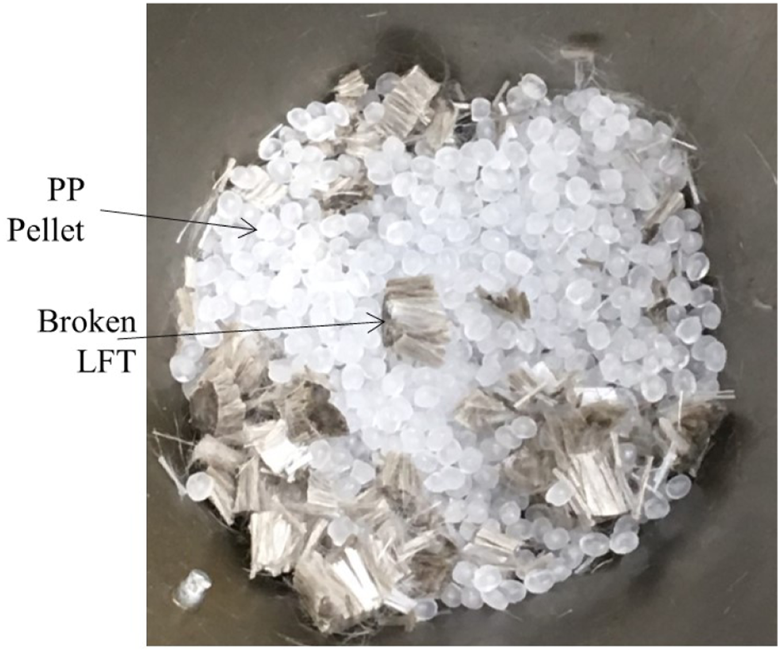
Figure 7(a) shows the dog-bone coupons after the injection molding. Specimens made with pure PP and with Flax/PP LFT pellets. The pure PP dog-bone coupons were fully transparent. All Flax/PP dog-bone coupons had very similar appearances. The dog-bone coupons made out of the high void LFT pellets led to the same injected coupons’ appearance, being opaque and a dark brown color. The fiber distribution in the dog-bone coupons appeared to be evenly and randomly oriented. However, there were some areas in the dog-bone coupons that were a light brown colour. These areas are attributed to bundles of less impregnated flax fibers. Those bundles are not favoured since they indicate inefficient integration between the polymer and the fiber. Yet, this is a typical appearance for biocomposites produced using LFT pellets and injection molding. According to Chaitanya et al.
52
it is typical that the injection molding process causes the long fibers to bend and twist during processing, leading to the formation of fiber clusters within the produced biocomposites. Figure 7(b) Microscopic images of the injected coupons produced using LFT pellets having 22% void content; the highest void content. No void can be observed in the injected copouns. The white lines are traces of flax fibers pullouts which were caused by the polishing process and the low chemical interaction between flax fibers and PP. This finding indicates that irrespective of the LFT void content, the injection molded coupons did not have any void. The dog bones post-injection. (a) Pure PP and Flax/PP. (b) Microscopic images of the injected coupons produced using LFT pellets having 22% void content. No void can be observed in the injected copouns. The white lines are traces of flax fibers pullouts which were caused by the polishing process and the low chemical interaction between flax fibers and PP. PP: polypropylene.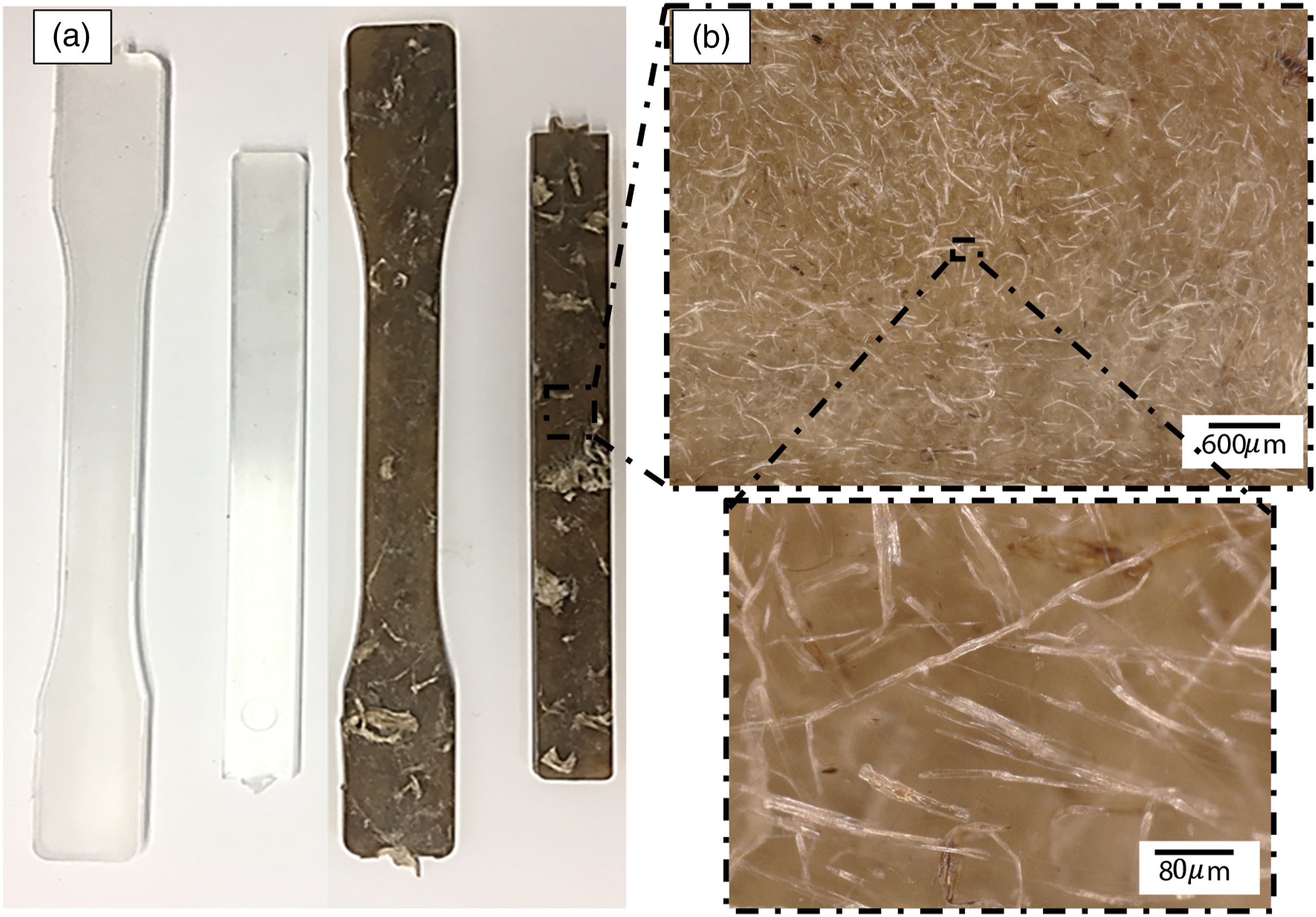
Mechanical properties of the injected parts
Figure 8 presents the impact strength of the injection molded parts as function of void contents and LFT pellets' lengths. The specimens were made with (a) 6 mm and (b) 15 mm LFT pellets. The quasi-continuous LFT pellets resulted in an overall increase in impact strength. The pure PP injection molded parts had an impact strength of 2 kJ/m2. All the other injection molded parts had higher impact strength than the pure PP. The LFT pellets with lowest void content, 4%-6 mm and 4%-15 mm, resulted in an impact strength of 5367 ± 218 and 7469 ± 551 The impact strength of the injection molded parts as function of LFT pellet void content and LFT pellet's length. (a) specimens made with 6 mm LFT pellets and (b) specimens made with 15 mm LFT pellets. LFT: long fibre-reinforced thermoplastics.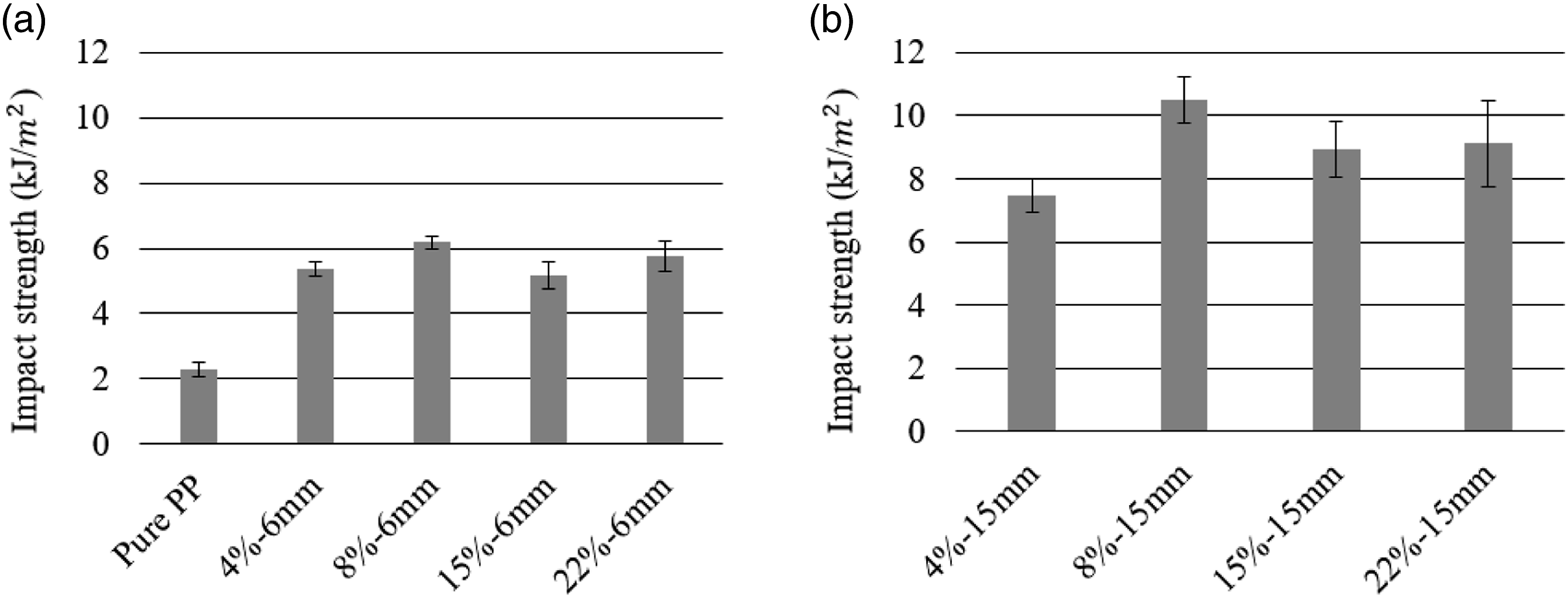
Overall, the impact strengths for the 15% and 22% void contents were very comparable to the specimens produced with lower void content LFT pellets. However, the specimens produced using high void content LFT pellets required manual intervention during the injection molding process. Thus, the manual intervention was mostly responsible for improving the mixing quality in the hopper of the injection molding machine. In addition, the specimens produced using LFT pellets with having higher void content had wider standard deviations. This high standard deviation occurred possibly due to the inconsistent mixing during the injection molding experiments.
Figure 9 presents the tensile properties of injection molded parts as a function LFT pellet’s void content and LFT pellet’s length; (a) presents the modulus strength for injection molded parts made using 6 mm LFT pellets and (b) using 15 mm LFT pellets. It should be noted that in all cases the addition of flax fibers led to an increase in stiffness compared to the pure PP sample. The 8%-15 mm specimens had the highest tensile modulus average of 4652 ± 113 MPa, a value which was more than twice as high as the pure PP tensile modulus of 1817 ± 106 MPa. For the specimens made using shorter pellets, shown in Figure 9(a), the modulus slightly increases between specimen 4%-6 mm to 8%-6 mm, then slightly increases again to 15%-6 mm and then stabilizing at approximately the same value. However, the difference in modulus values between 8%-6 mm, 15%-6 mm and 22%-6 mm seems insignificant, and the pooled average modulus of the three conditions is 3764 ± 192 MPa. This indicates that the fiber content and orientation is similar in all cases. Furthermore, the fiber degradation for specimen 4%-6 mm was the highest and specimen 8%-6 mm was the second highest. As seen in Table 4, the 4% void content LFT pellets, which were produced at 50 mm/minute, experienced significantly higher thermal degradation. This explains the lowest modulus measured for 4% void content LFT pellet injected coupons. (a) and (b) The tensile modulus of injection molded parts as a function LFT pellet’s void content and LFT pellet’s length. (c) The maximum tensile strength of the injection molded parts as a function LFT pellet’s void content and LFT pellet’s length. No differnce can be observed. This finding indicates that poor bonding between the flax fibers and the polypropylene polymer.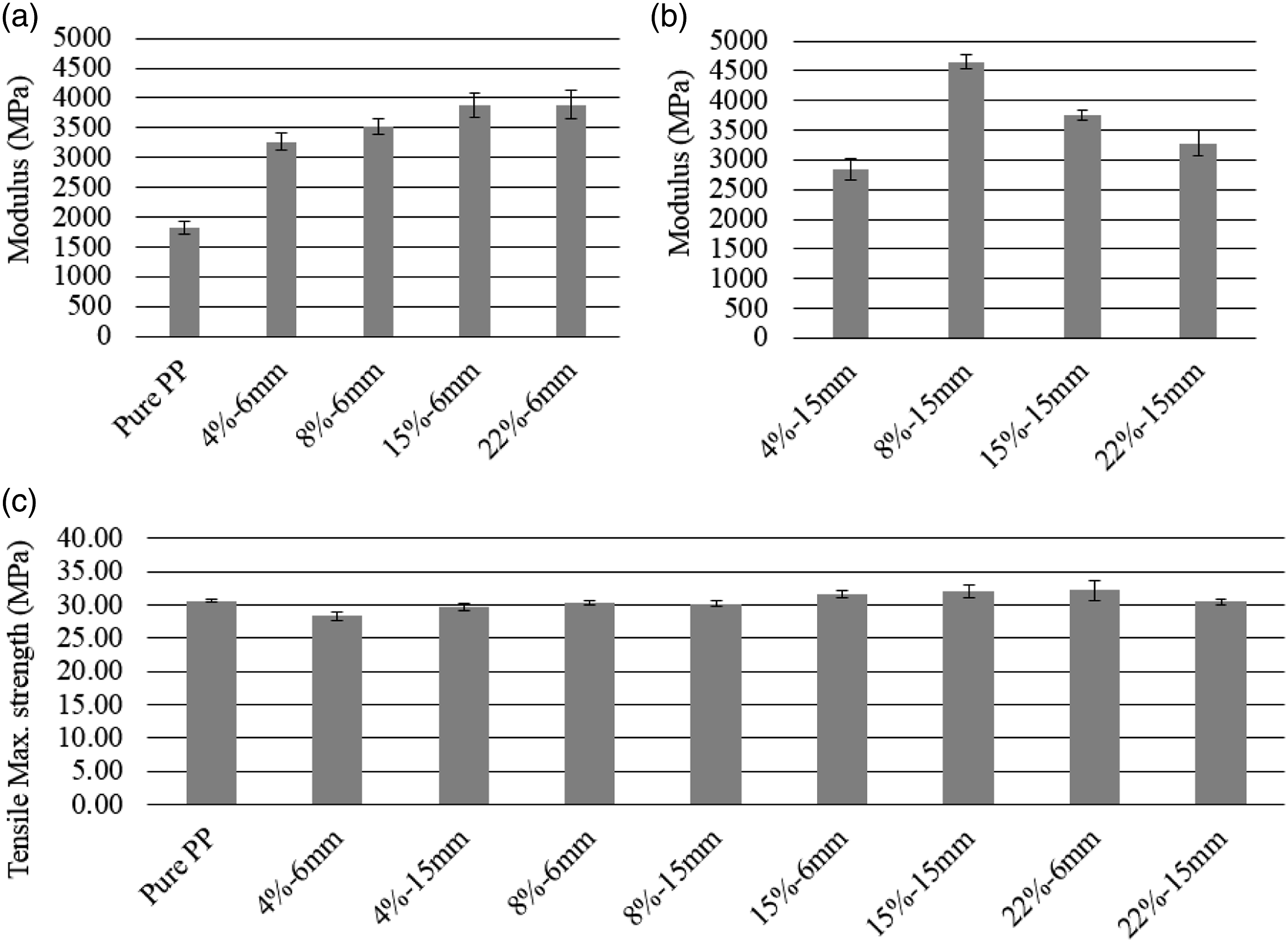
For the longer pellets shown in Figure 9(b), the 8%-15 mm had the highest tensile modulus average of 4652 ± 113 MPa. The difference observed with the 4%-15 mm pellets is striking. The modulus value of the 4%-15 mm pellets is 2837 ± 182 MPa, that is, 39% lower than the 8%-15 pellets. This difference is attributed to the thermal degradation due to longer thermal exposure during pultrusion. This may have weakened the flax fibers and resulted in shortening during injection molding. Further studies are needed to verify this explanation. The lower modulus values for 15%-15 mm and 22%-15 mm are attributed to the lower load transfer caused by the bundling and improper mixing of dry flax fibers during injection molding. Thus, the inadequate flax fiber distribution was likely the cause behind the drop in modulus.
In comparing Figure 9(a) and (b), it is observed that, except for the 8%-15 mm, the coupons made using shorter flax fibers resulted in a higher tensile modulus than the longer flax fiber reinforced biocomposites. This is counter-intuitive since longer fibers provide higher surface for stress transfer, which results in higher modulus. The 15%-15 mm and 22%-15 mm modulus values, of 3744 ± 81 MPa and 3283 ± 221 MPa respectively, are equivalent or lower than the pooled average modulus of the 8%-6 mm, 15%-6 mm and the 22%-6 mm coupons. In this case, the lower modulus values are attributed to fiber entanglement due to the fiber clustering during injection molding. An increase in the modulus can be generally attributed to an improved dispersion of the fibers within the biocomposites enabling better stress transfer between fibers and the polymer.53–55 Chaitanya et al. 52 observed that long fibers in LFT biocomposites bend and entangle with each other forming fiber clusters, thus impeding uniform dispersion and orientation of fibers within the biocomposite. Therefore, it is likely that the manual intervention to mix the unimpregnated fibers in the injection machine hopper was insufficient to properly mix and detangle the fibers in the injected coupons.
Figure 9(c) presents the maximum tensile strength of the injection molded parts as a function of void content and length. As can be seen in the figure, there is no significant difference between specimens in the maximum tensile strength. All results are around the value of 30 MPa. Also, it is observed that the addition of flax fibers in the PP did not improve the maximum tensile strength compared to the pure PP dog-bone coupons. This finding was expected since there is normally a very low chemical interaction between the hydrophilic fibers, such as flax fibers, and hydrophobic polymers, such as PP, resulting in a low interfacial strength. 56 Adhesion between the polymer and the reinforcement fiber is an important characteristic to improve the mechanical strength of a composite part. 57 Yet, it is worth mentioning that the dog-bone coupons did not contain any coupling agent to improve adhesion which could improve the tensile properties of these samples. This result confirms similar findings by Barkoula et al. 49 Typically, MAPP can be used as the coupling agent to improve wettability for natural fiber/PP composites.58–61
Morphological analysis of the injection molded specimens
Figure 10 shows the SEM images of an impact fractured region. Typical SEM images are represented in (a) & (b), showing smooth surfaces at the flax fibers as well as fiber pull-outs after the impact fracture. The smooth surfaces indicate that the flax fibers had weak adhesion and chemical interaction with the PP polymer. The low chemical interaction between the flax fibers and PP was the cause behind making the maximum tensile strengths unchanged relative to pure PP as seen in Figure 9(c). Figure 10(c) 8%-6 mm & (d) 8%-15 mm show paired specimen which had the same void content but was produced using a different LFT pellet length. As can be seen in Figure 10(d), the SEM image shows relatively longer fiber compared to 8%-6 mm specimen, even after the impact fracture. The longer fibers could explain the improvement of the impact strength of the 15 mm LFT pellets compared to the 6 mm LFT pellets. SEM images of impact fractured regions. (a) & (b) represent typical SEM images showing smooth surfaces at the flax fibers as well as fiber pull outs after the impact fracture. The smooth surfaces indicates that the flax fibers had weak adhesion and chemical interaction with the PP polymer. (c) 8%-6 mm & (d) 8%-15 mm are paired specimen which had the same LFT pellet's void content but was produced using a different LFT pellet’s length. As can be seen in (d), the SEM image is showing relatively longer fibers compared to the specimen produced using the 6 mm-long pellets even after the impact fracture.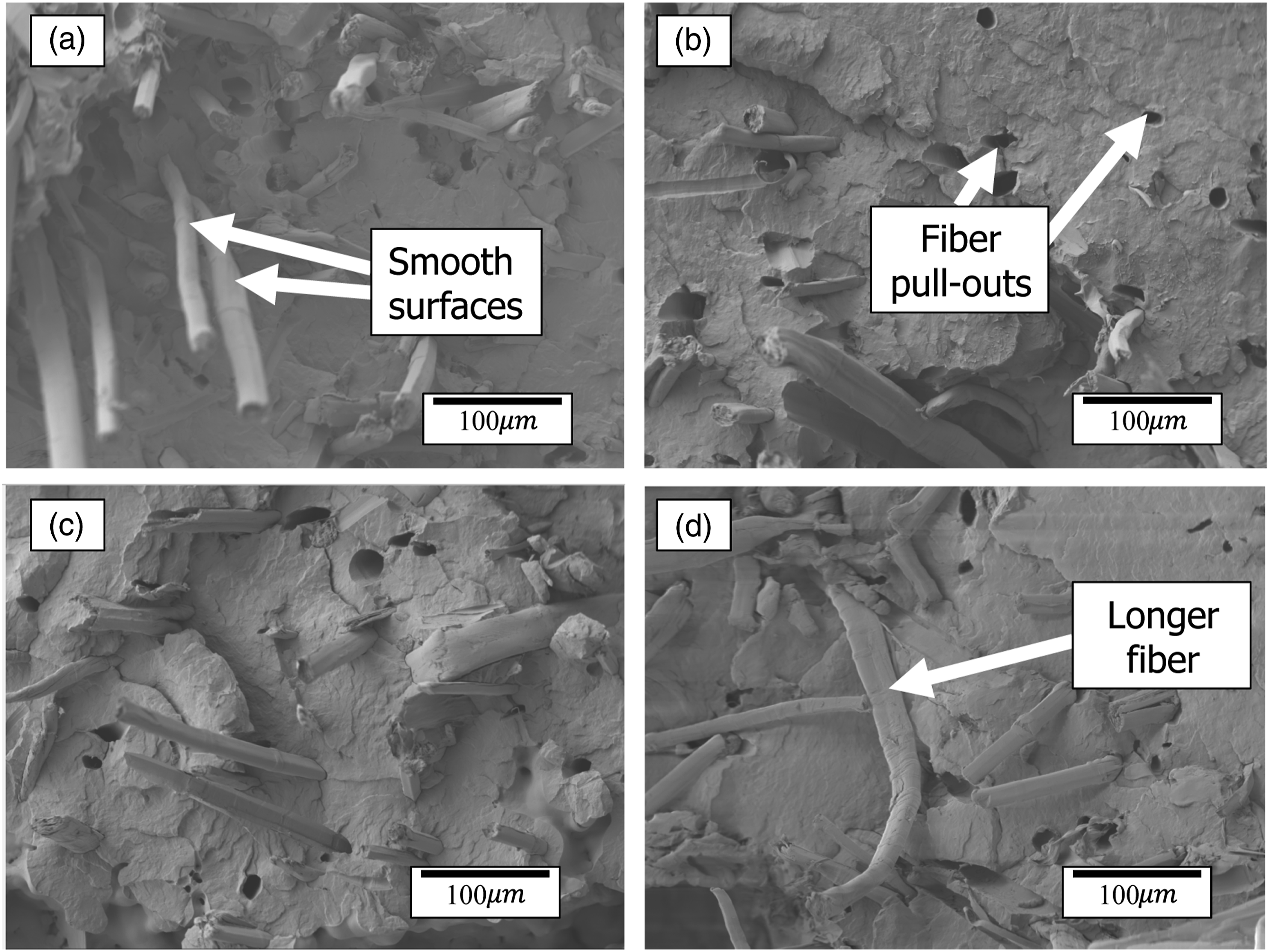
Conclusions
This study investigated the effects of LFT pellets’ void contents during the pelletizing process and on the mechanical properties of the injection-molded parts. The fiber volume content of the pultrudates was 50% and four void content points were tested between 4% and 22%. The pultrudates were pelletized into two different lengths of 6 and 15 mm. Three sets of dog-bone coupons were injection-molded using a combination between the void contents and the LFT pellets' lengths. The LFT pellet’s void content was found to have an influence on the LFT pelletizing quality as well as on the mechanical properties of the injection-molded parts. Flax/PP rods pultruded at 50 and 250 mm/min had void contents up to 8%. These rods were cut into well consolidated pellets. These structurally integral pellets were injection-molded without any issues. Flax/PP rods produced at 500 mm/min and 1000 mm/min led to void contents above 15%. The pelletizing process of these poorly impregnated rods was very damaging, resulting in broken pellets with exposed dry fibers. Manual intervention to allow the LFT pellets and dry flax fibers to sink in the injection molding machine was required. The mechanical properties of the injection-molded parts using high void LFT pellets resulted in less consistent values attributed to inadequate flax fiber distribution. The mechanical properties of the injection-molded parts using low-void LFT pellets resulted in more consistent values. The highest recorded impact strength was 10,515 ± 730 J/m2, corresponding to an experiment that was done using 15 mm LFT pellets with around 8% void content. These pellets were cut from rods pultruded at 250 mm/min. The LFT void content and length did not have any influence on the maximum tensile strengths of the injection-molded parts. All SEM images showed that the exposed fibers had smooth surfaces, indicating very low chemical interaction between the flax fibers and PP. Irrespective of the LFT void content, the injection molded coupons did not have any voids. Finally, further work will need to be conducted on the parameters of the injection molding machine such as using different injection speeds and pressure values to confirm the effects of Flax/PP LFT pellets’ morphology on the mechanical properties of injection-molded parts. This will help applicable industries, which make LFT components, to choose the appropriate void contents and injection molding parameters. Also, future work will characterize, discuss and improve the seemingly poor interfacial properties between flax and PP and thoroughly investigate the blending of flax-PP compatibilizing agent with Flax/PP LFT pellets.
Footnotes
Acknowledgements
The authors would like to thank Danielle Szydlowski for her help with pelletizing pultrudates. We would like also to thank Bombardier Aerospace, Pultrusion Technique, Saudi Arabia’s Saline Water Conversion Corporation and Ministry of Education (KSP12014087), NSERC (CRDPJ488387-15) and Prima Quebec (R10-009) for financing this research project.
Declaration of conflicting interests
The author(s) declared no potential conflicts of interest with respect to the research, authorship, and/or publication of this article.
Funding
The author(s) disclosed receipt of the following financial support for the research, authorship, and/or publication of this article: This work was supported by the PRIMA Quebec (R10-009), Natural Sciences and Engineering Research Council of Canada (CRDPJ488387-15), Saudi Arabia’s Saline Water Conversion Corporation and Ministry of Education (KSP12014087).
Data availability
The raw/processed data required to reproduce these findings cannot be shared at this time due to technical or time limitations