
Abstract
The present paper has experimentally determined the flexural strength of a glass fiber reinforced polymer sandwich panel with a novel M-shaped lattice core reinforced by nano-silica (nano-SiO2). For this purpose, a polymer composite sandwich panel with an M-shaped core made of glass-epoxy fiber has been fabricated in this experiment using the vacuum-assisted resin transfer molding method. Afterward, polyurethane foam (PU) was injected into the empty space of the sandwich panel. In order to determine the flexural strength of the sandwich panels, they have been subjected to three-point bending and compressive loads. From the results of the study, it was figured out that: (a) Adding 1–3 wt% of nano-silica into the glass fiber had the most desirable effects on the enhancement of flexural strength of the sandwich panels (b) PU has improved the flexural strength of sandwich panels (c) The new M-shaped core can well postpone the buckling and failure of the composite sandwich structures.
Keywords
Introduction
Sandwich panels are made of two plates,1–7 top and bottom, with a lattice core, which is made of composite material. A high strength-to-weight ratio is the main character in the sandwich panels. 8 The primary role of the lattice core is to keep the surface sheets separated and make the whole panel resist vertical deformations like a single plate. Composite sandwich panels with lattice cores have broad applications in transportation, automotive, aerospace, and marine structures due to their low weight and high strength. The geometry of the lattice core has a significant effect on load distribution. 9 Many kinds of research have been performed on the mechanical properties of the composite sandwich panels, such as compressive strength, three-point bending strength and specific bending strength.
Epoxy resin is one of the most used thermosetting polymers and is often reinforced by fibers known as fiber-reinforced polymer (FRP).10–12 FRPs contain two or more fiber layers that make a laminate with the independent structural element with high bending stiffness.13,14 Carbon fibers reinforced polymer (CFRP) and glass fibers reinforced polymer (GFRP) are typical examples of FRP used in fabricating sandwich panels. One of the most critical parts of the sandwich panel is the core. Cores are made of different light materials, such as metals, composites, wood, and plastics, with different structures and geometric designs. Honeycomb, lattice core, and truss core are common types of core, which have exclusively specific features for use in various equipment. Many kinds of research have been performed on the mechanical properties of the composite sandwich panels, such as compressive strength, three-point bending strength and specific bending strength. Studzinski 15 has found the optimal design of sandwich panels with flat steel facings and a hybrid core. The design vector consists of the geometrical parameters of the sandwich panel, including its span length and the parameter which describes the proportion of aerogel thickness to the total thickness of the core. The mechanical properties of the hybrid core were described by mathematical functions that were obtained in laboratory tests and optimization. Qi and Ma 16 investigated the mechanical response of pyramidal lattice truss core sandwich structures by additive manufacturing. Out-of-plane and in-plane compression and shear tests were carried out to measure the stiffness and strength properties of the structures. They compared the experimental results with numerical ones and found excellent agreement.
Sandwich structures as a good energy absorber used in many industries, especially in transport. Hence, many studies have been focused on the enhancement of impact resistance of sandwich structures. Zhang et al. 17 investigated the low-velocity impact of fully clamped rectangular multilayer sandwich plates with metal foam cores struck transversely by a heavy mass. Finally, numerical calculations of multilayer sandwich plates under low-velocity impact were conducted. Ahmadi and Liaghat 18 studied high velocity impact on composite sandwich panels with nano-reinforced syntactic foam core.
CFRP and GFRP laminates are a good candidate for use in the sandwich structures as faces due to their high strength and low weight. Both the metal and composite materials are appropriate for core cells in this state. Xu et al. 19 determined the mechanical response of carbon/epoxy composite sandwich structures with three-dimensional corrugated cores. MacDonnell and Sadeghian 20 investigated the experimental and analytical behavior of sandwich composites with GFRP facings and layered fiber mat cores. Partial-composite behavior of sandwich beams composed of fiberglass face sheets and woven fabric core was studied by McCracken and Sadeghian. 21 Structural behavior of sandwich beams with flax fiber-reinforced polymer faces and cardboard cores under monotonic and impact loads studied by Betts et al. 22 McCracken and Sadeghian 23 presented an experimental study on the behavior of sandwich beams made of green materials for both core and skin components. Emami et al. 24 presented an experimental investigation into single point incremental forming of GFRP sheet with different fiber orientations and volume fractions at elevated temperatures.
Using polyurethane foam (PU) in the sandwich panels is another new method that has many advantages. Some of the advantages of PU include low thermal conductivity that is lower than all other conventional insulation materials, lightweight, high impact strength, strong adhesion to many materials, low vapor permeability, high thermal resistance, and resistance to abrasion and cracking. These unique foam properties have made them widely used in many industries and structures, including sandwich structures. Hence, the mechanical and chemical properties of sandwich structures can be affected by foam inside the core. Using foam inside the core can improve the mechanical or chemical properties such as energy absorption, reducing vibration, changing the heat transfer rate and moisture, and also sound transmission.19,25,26 Fu and Sadeghian 27 studied the flexural and shear characteristics of bio-based sandwich beams made of hollow and foam-filled paper honeycomb cores and flax fiber composite skins. Betts et al. 28 investigated the experimental behavior and design-oriented analysis of sandwich beams with bio-based composite facings and foam cores. Khaledi and Rostamiyan 29 experimentally and numerically investigated the bending and compressive behavior of foam-filled carbon fiber epoxy sandwich panel with truss-core. Rivallant et al. 30 studied the buckling of foam-filled stabilized composite beams using analytical Modelling and experiment method.
In recent years, nano-materials have helped researchers to make composite materials with superior characteristics. Nanoparticles often have unique and specific properties such as mechanical, chemical, and optical, that can affect the properties of the other materials (Nano-materials) as they are added to them. Silica, carbon nanotube, clay, and Graphene Oxide are the standard nanoparticles used in composite materials to enhance mechanical or chemical properties. Rostamiyan and Azadi 31 investigated the buckling strength of the new hybrid nanocomposite laminates using a combination of layered and particulate nanofillers. Borrego et al. 32 studied the fatigue behavior of glass fibre reinforced epoxy (GFRE) composites enhanced with nanoparticles. Kendall and Meguid 33 considered the effect of carbon nanotube waviness on the active damping of laminated hybrid composite shells. Sprenger 34 investigated the effects of silica nanoparticles in toughened epoxy resins and fiber-reinforced composites. Agwa et al. 35 experimentally and analytically investigated the water diffusion process in nano-carbon/alumina/silica filled epoxy nanocomposites. Azadi and Rostamiyan 36 experimentally and analytically studied the buckling strength of new quaternary hybrid nanocomposite using the Taguchi method for optimization. Rostamiyan et al. 37 optimized the mechanical properties of epoxy-based hybrid nanocomposite with different compositions of nano-silica as nano reinforcement, high-impact polystyrene as thermoplastic phase, and hardener by applying the simplex-centroid mixture design method to achieve the ultimate tensile, flexural, compression and impact strength. Yaghoobi and Taheri 38 presented an analytical and statistical solution to analyze the buckling capacity of sandwich plates with uniform and non-uniform porous core reinforced with graphene nanoplatelets. Sun et al. 39 investigated the effect of hydrogen functionalized graphene on tensile properties of polymer nanocomposites by using molecular dynamics simulations.
It is simple and easy to add nanoparticles to the composites to improve the strength of the sandwich panels. It is mentioned that to achieve the higher properties for the nano-materials need to add optimum content of nanoparticles to the nano-materials. On the other hand, it has been observed that adding an inappropriate amount of nanoparticles can lead to a decrease in the final strength of the nano-material.40,41
In the present study, compressive and three-point bending tests for the GFRP sandwich panel with the novel M-shaped truss core are experimentally performed and the results are compared with the foam-filled sandwich panel. In addition, the nano-silica are added to the epoxy matrices with four different weight percentages of 1%, 2%, 3%, and 4% to find the effect of adding nano-silica to the bending and compressive strength of the sandwich panels.
Material description
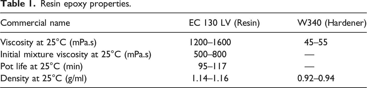
Resin epoxy properties.
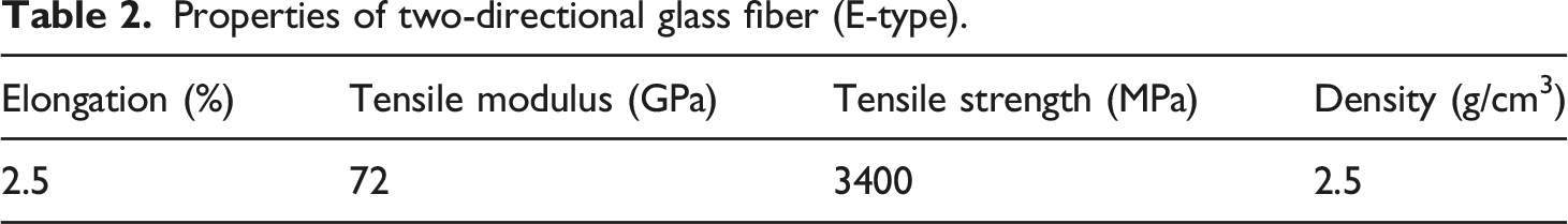
Properties of two-directional glass fiber (E-type).
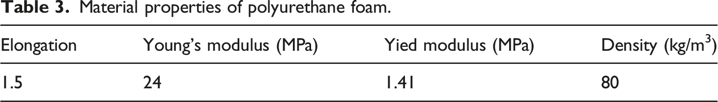
Material properties of polyurethane foam.
Design and fabrication steps
This section introduces the design and fabrication steps of a sandwich panel with an M-shaped core. In order to achieve a laminate without any porosity, the method of vacuum-assisted resin transfer molding (VARTM) method has been used in the first step.
25
The epoxy resin was subjected to a frequency of 30 kHz and a power of 150 W for 10 min by an ultrasonic device, at which point the hardener was added to the mixture in a ratio of 100:15. In this process, after placing the glass fibers in the vacuum bag (Figure 1) and creating a partial vacuum on it, the resin passes through the mold from inside the tube so that the whole bag is filled evenly. The produced face sheet includes eight layers of glass fiber woven with epoxy resin. The fabricated samples are vacuum placed for 12 h at room temperature to be completely dried. Eventually, the samples are then placed in an oven at 60°C for 4 h. For the nano-composite laminates, the nano-silica with the pre-determined weights were first mixed mechanically with the magnet stirrer and then placed inside the ultrasonic homogenizer machine for 10 min to create a homogeneous mixture. The final thickness of laminated samples is 2 mm. Vacuum bag pump.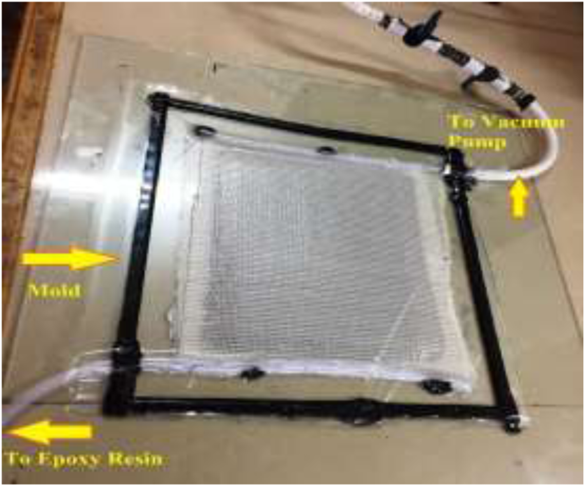
Sandwich panel fabrication
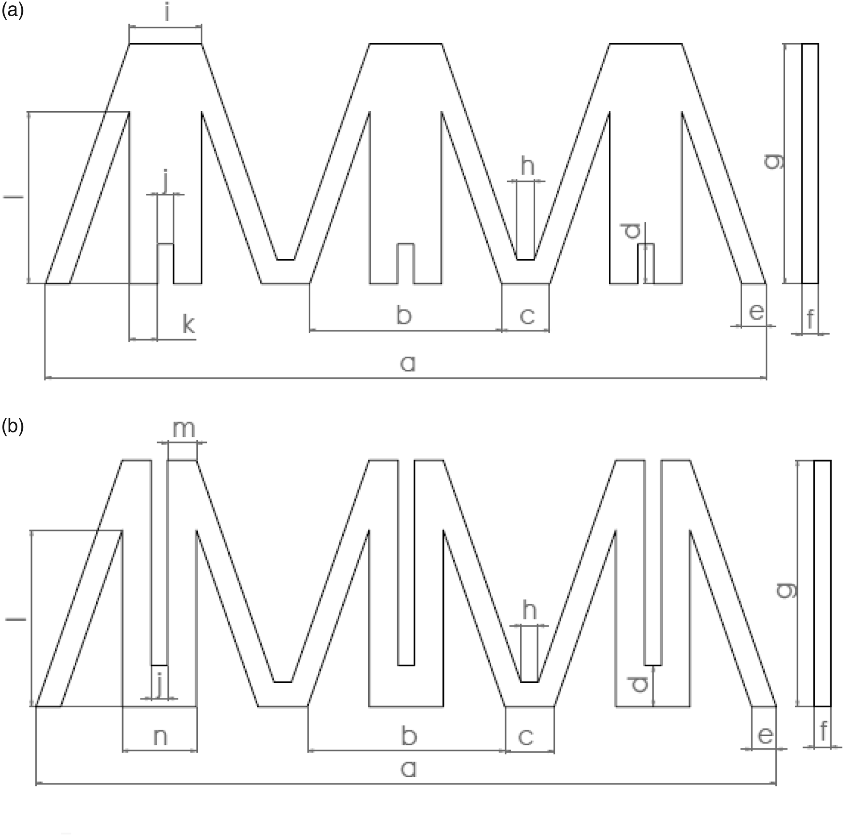
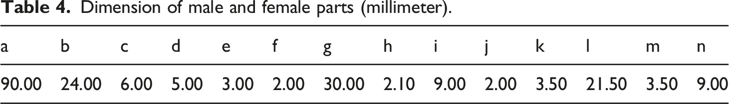
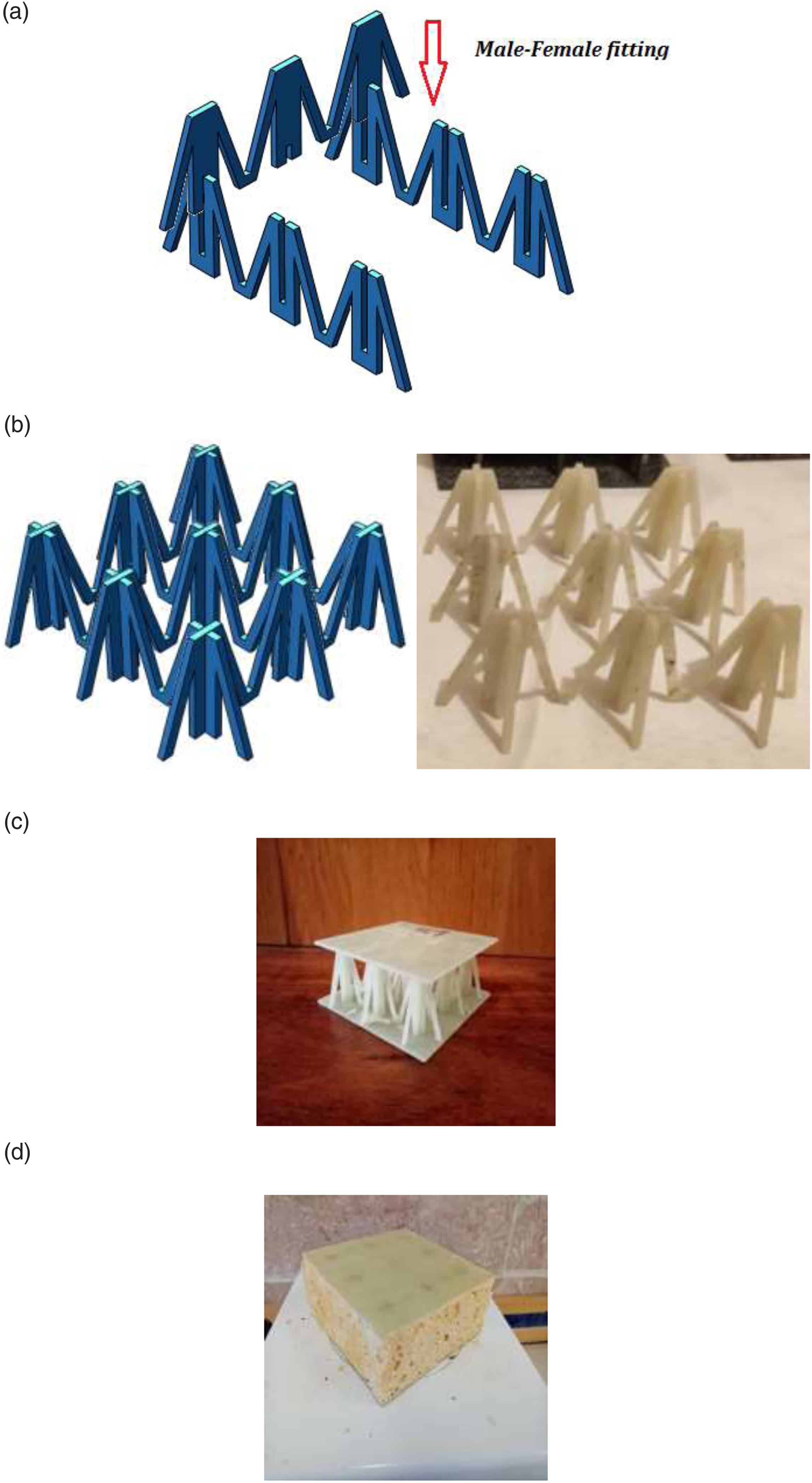
Next step is to fabricate sandwich panel with novel M-shaped core. The composite sandwich panel consists of two face sheets and an M-shaped lattice truss core (Figure 2). The M-shaped core is composed of three female parts and three male parts that every part has three trapezoidal unit cells. The core components have been designed as male and female parts in way that be assembled to each other without any need to glue. The schematic view of the female and the male parts have been shown in Figure 3. Also, dimension of the female and the male parts have been presented in Table 4. Configuration of composite sandwich panel with M-shaped lattice core. Schematic view of core components: (a) male part (b) female part. Dimension of male and female parts (millimeter).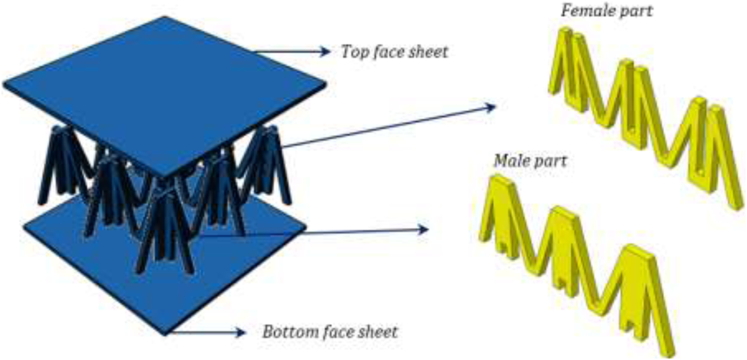
According to the construction plan, the laminates are cut by water jet cutting operation to make the female and male parts (Figure 4(a)). Images from the edge of the cut parts have been shown in Figure 4(b). Then, the resulting patterns were assembled into each other with male-female fitting (Figure 5(a)) to produce an M-shaped lattice core (Figure 5(b)). As seen in Figure 2, the two face sheets, which have a dimension of 90 mm length, 90 mm width and 2 mm thickness, are placed on the top and bottom of the core with epoxy resin. To attach the laminates to the core, sandwich panels are placed inside oven for 9 h at 40°C. Finally, the sandwich panel was fabricated with dimensions of 90 mm × 90 mm × 34 mm (Figure 5(c)). The sandwich panel has been surrounded from three areas by molded rectangular plates, then dust and grease have been removed from inside of the sandwich panel for complete and uniform adhesion. Afterward, two materials, polyol and isocyanate with a density of 80 kg/m3, were injected to the selected location, and then they made a chemical reaction that forms the foam, and as a result, they filled the space and pores between the M-shaped core and face-sheets. One of the features that distinguish this foam from similar fillers is its adhesive property, which is compatible with all surfaces and sticks to all surfaces of the structure without the need for additional elements. Finally, the extra foam coming out of the sides of the sandwich panel is cut after rigidization. The foam-filled sandwich panel was made, as shown in Figure 5(d). (a) Schematic view of cutting laminate by waterjet machine. (b) Images from the edge of the cut parts. (a) Male-female fitting (b) Fabricated M-shaped core (c) Fabricated composite sandwich panel (d) Fabricated foam-filled composite sandwich panel.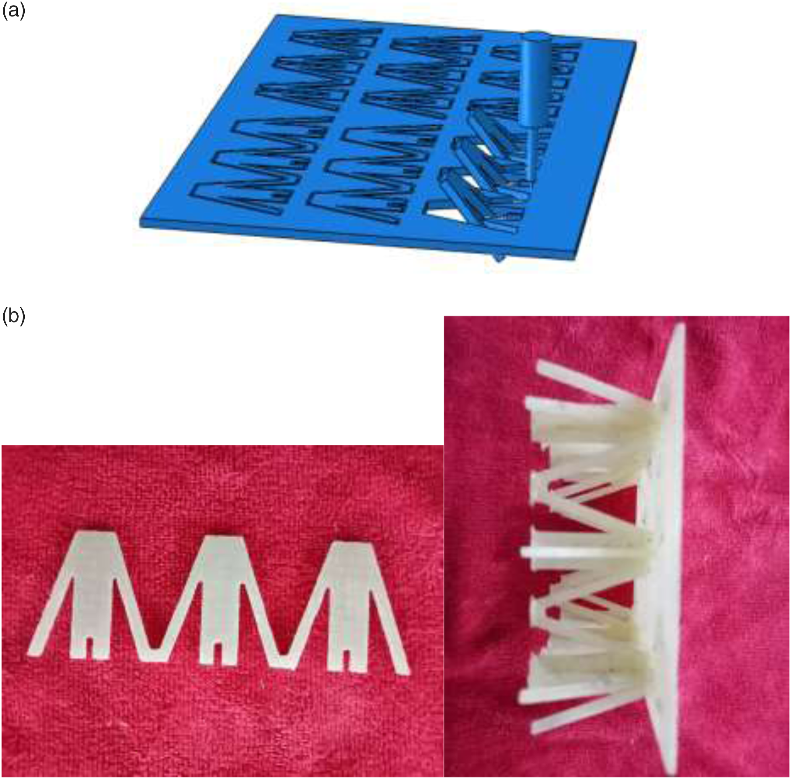
Experiments
All of the mechanical tests in the present research have been performed by a SANTAM testing machine with axial actuators. The SANTAM has a static capacity of 150 KN, with a maximum stroke of 300 mm. A constant movement rate of 0.5 mm/min of the movable head of the testing machine was applied through all types of mechanical tests.
The laminates have been tested in the tensile properties direction to determine the mechanical properties of the parent material used to manufacture the lattice cores and laminate sheets. As mentioned, tests were conducted on rectangular specimens in accordance with ASTM D-3039
42
by using SANTAM STM-150 hydraulic device. The constant movement rate of the movable head of the testing machine was 0.5 mm/min. The gages under test are rectangular-shaped with dimensions of 250 mm × 25 mm × 2 mm (Figure 6). Sandwich panel with M-shaped core during three-point bending test.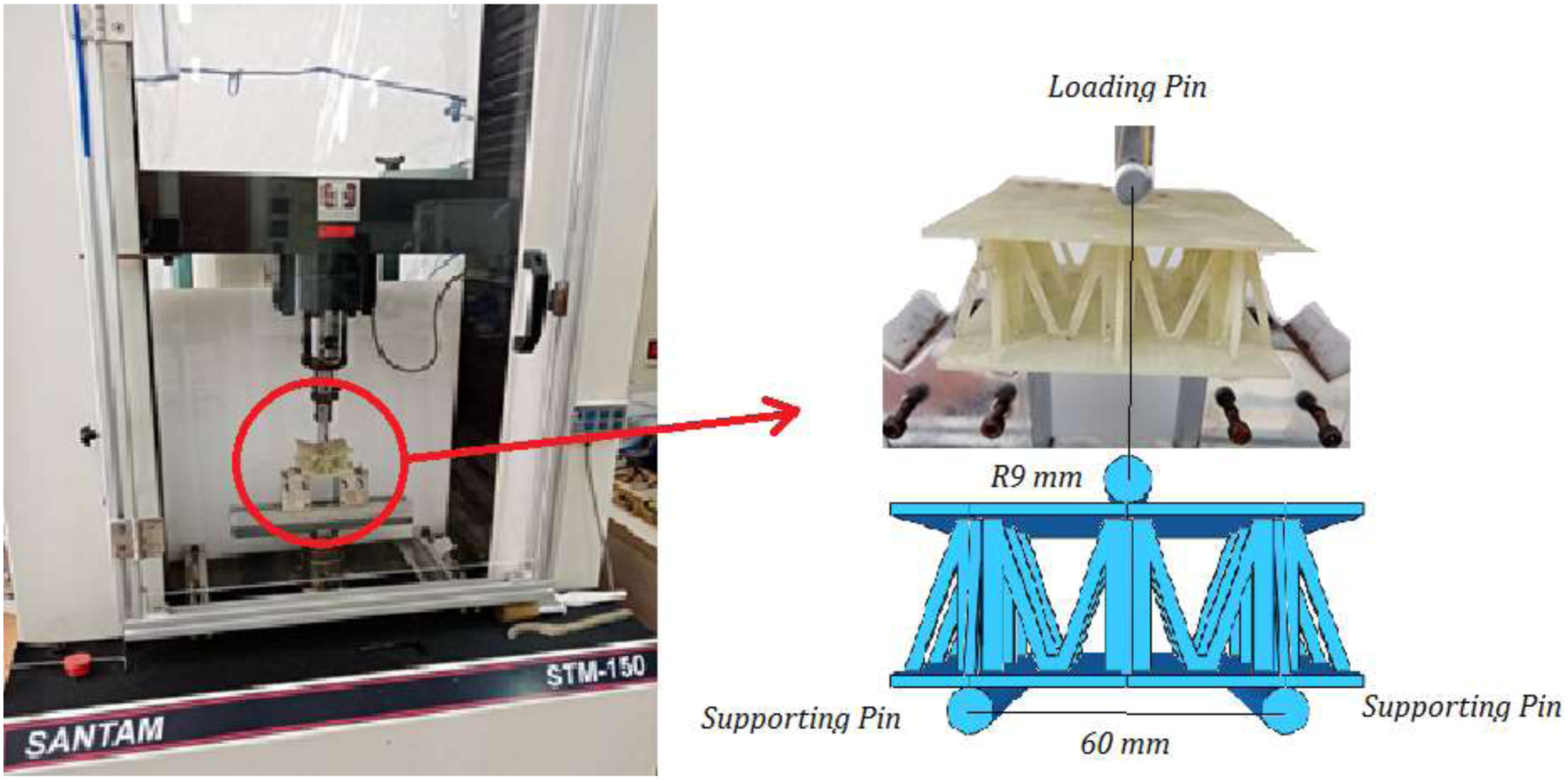
Three-point bending test
In order to determine the mechanical behavior of the composite sandwich panel, three-point bending test using a cylindrical rod with a 4.5 mm radius is implemented.
Compressive test
In order to determine the compression behavior of the composite sandwich panel, the compressive load has been applied on the panels. Single laps flatwise compressive tests were conducted on the M-shaped core panels in accordance with the standard test for sandwich core material. Flatwise compression tests were performed according to the ASTM C365
43
test standard. For the flatwise compression test, the specimen with an area of 90 mm×90 mm×34 mm were put on a self-aligning spherical bearing block. Figure 7 shows the specimen mounted on the testing machine. Flatwise compression test setup before the comparison test.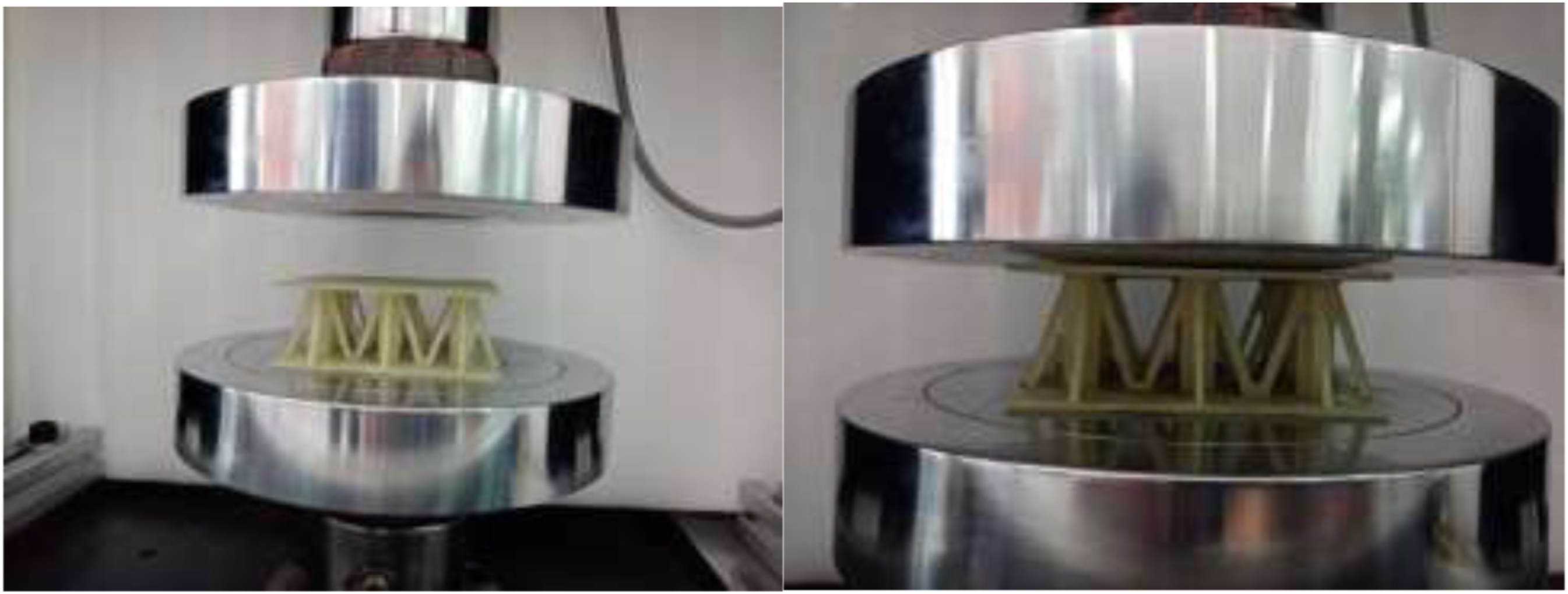
Result and discussion
Results of tensile test of laminates
Figure 8 shows the stress-strain diagram obtained from the tensile test. The test is performed on the rectangular laminate specimens. According to this figure, it can be seen that the laminates containing 3 wt.% of silica had the maximum strength, and also, with adding nano-silica from 1 to 3 wt.%, the strength of samples had a significant upward trend and has reached a maximum value for 3 wt.% of nano-silica. However, it is also observed that with an increase of more than 3 wt. % of nano-silica, for instance, 4 wt. % of nano-silica, the uptrend has stopped and the strength decreases suddenly that the laminates containing 3 wt.% of silica had the maximum strength, and also, with adding nano-silica from 1 to 3 wt.%, the strength of samples had a significant upward trend and has reached a maximum value for 3 wt.% of nano-silica. Stress-strain diagram for different amount of nano-silica.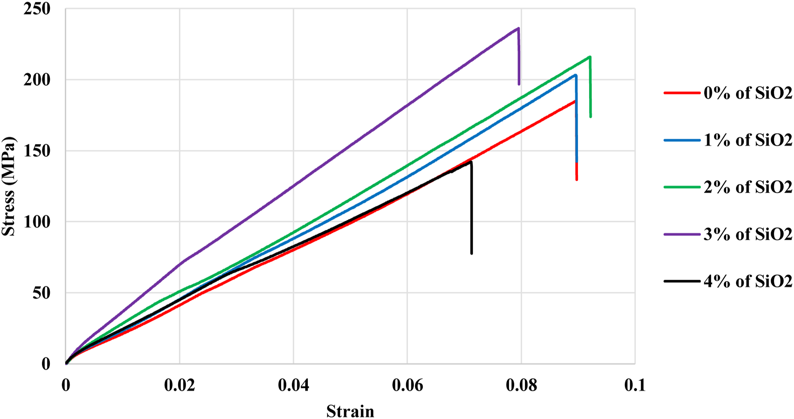
The nature of nano-silica can explain these results according to the Scanning electron microscope (SEM) images. Figure 9 is related to the laminate specimens after the tensile test. According to the SEM images, it can be determined that nano-silica as nano-fillers have an excellent chemical bending with the epoxy matrices that result in a high elastic modulus of the nanocomposites. Also, the SEM images of samples containing 3 wt.% of silica show that the nano-silica were settled among and around the initial cracks and can prevent the crack growth and delay the failure. Consequently, the ultimate strength of the composite increases. As mentioned before, the higher content of nano-silica decreases the tensile strength of the composites compared to the composites containing lower amounts of nano-silica (1–3 wt. %). Higher content of nano-silica causes a rough and brittle surface and a saturation state in the epoxy and thus can reduce the mechanical strength of the composite. Also, nano-silica act as an impurity that can reduce the mechanical strength of samples with a high content of nanoparticles. SEM Image of polymer resin field and suitable distribution for (a) 0% (b) 1% (c) 2% (d) 3% weight percentage of nano-silica.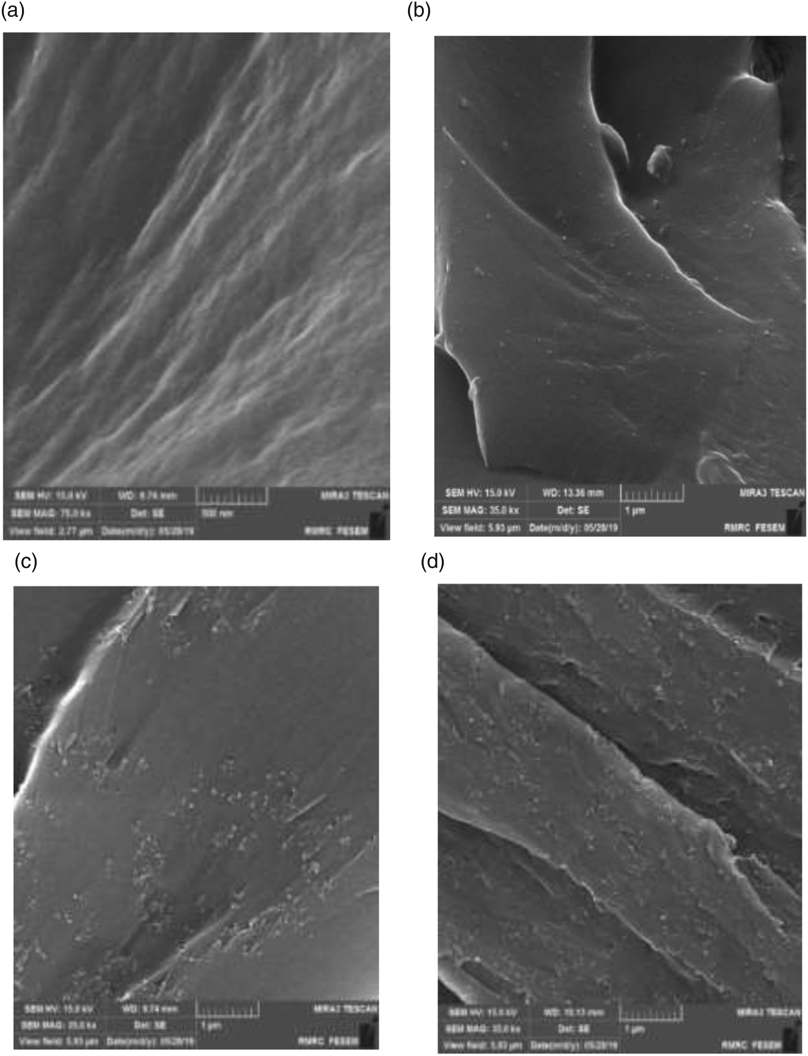
Results of flatwise-compression
After analyzing and investigating the results of the tensile tests of laminates, the flatwise-compression tests on the sandwich panels are performed and the results are shown below according to the force-displacement curves. This section discusses the effect of core design, PU Foam, and nano-silica on the ultimate strength and failure mechanism of sandwich panels under compression test. Flatwise-Compression test has been performed using a universal testing machine with 0.5 mm/min crosshead speed loading. The compressive load was applied to all specimens with the same conditions and repeated three times for each sample to verify its accuracy. The sample was placed below the movable crosshead jaw. After the test is completed, the results are collected and displayed through computer software. Then the obtained data were analyzed to study about mechanical properties of the M-shaped core structure.
Effect of SiO2 on the compressive strength of M-shaped sandwich panels
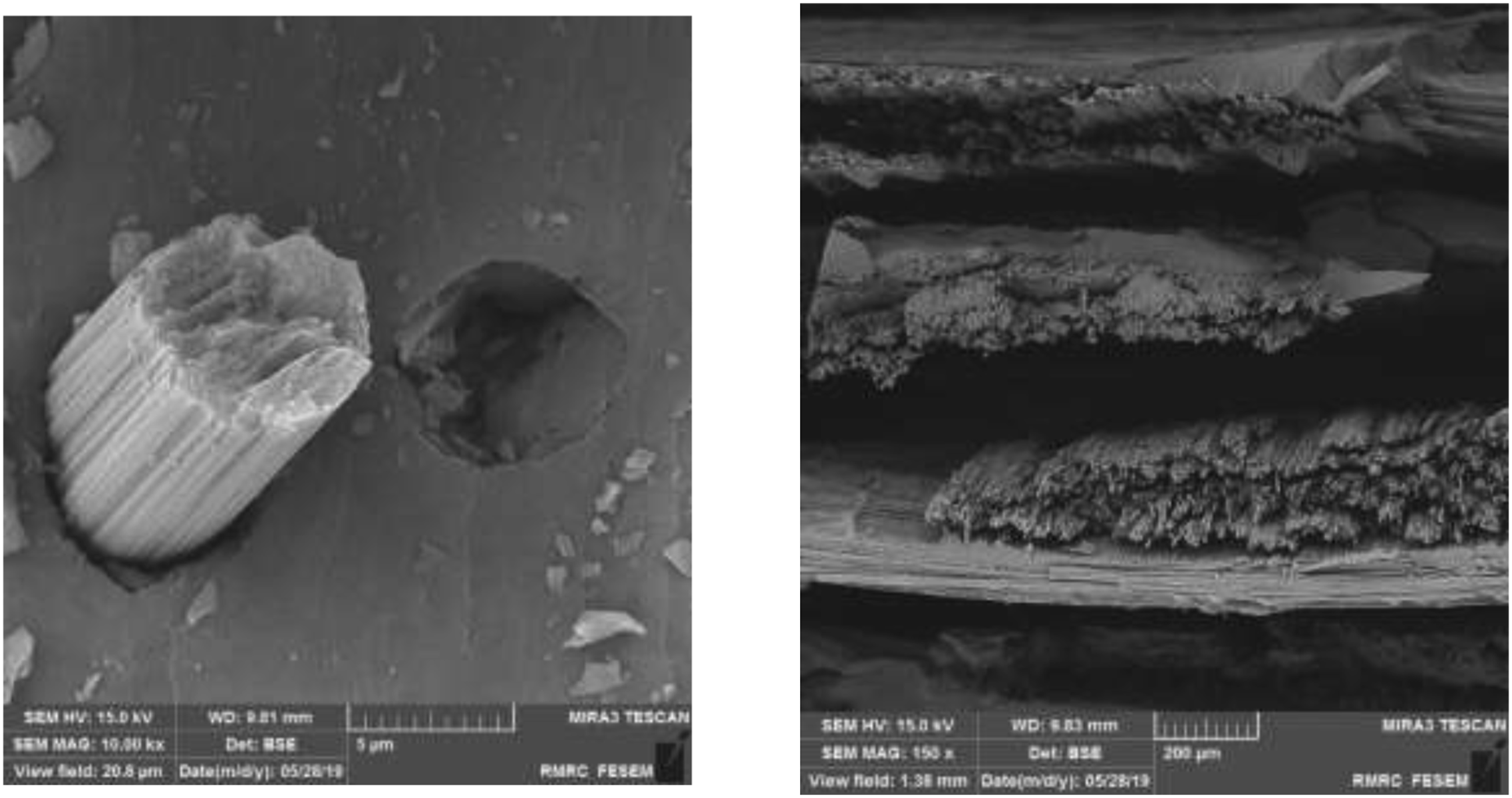
Figure 10 shows the force-displacement diagram for the compressive test. According to the results, it can be observed that the nano -silica had a significant effect on the compression strength of the sandwich panels. By adding up to 3 wt.% of nano-silica, the ultimate strength of sandwich panels is increased about 11, 22, and 33% compared to the neat samples. Also, the addition of 4% silica significantly reduced the ultimate strength of the samples and even about 22% less than the neat sample. SEM images related to the samples after the compression test are shown in Figure 11. These pictures showed an excellent bonding between the nano-silica and epoxy particles that improved the toughness of sandwich panel parts (faces and core) and decreased the stress concentration by distributing the loads. In 1 wt.% and 2 wt.% nano-silica samples, the distance between the dispersed nanoparticles between fibers and epoxy is greater than in 3 wt.% nanoparticle samples. And in the 3 wt.% nano-silica samples, this distance is reduced and the nanoparticles can prevent the growth of cracks more, thus delay the failure of the samples and the samples show more resistance. The results of the present study show that by adding from 1 to 3 wt.% of nano-silica, the strength of the samples had a significant upward trend and has reached a maximum value for 3 wt.% of nano-silica. However, adding more than 3 wt.% of nano-silica causes porosity and crack growth in the samples, which results in weakening and faster failure in them. Also, by adding more than 3 wt.% of nano-silica to the epoxy resin, the viscosity of the epoxy is greatly increased and it does not spread evenly between the fibers and high viscosity is created in it, and this problem causes weaker and faster failure of samples containing more than 3 wt.% nanoparticles. Force-displacement curves of compression test (M-shaped sandwich panels with nano-silica). SEM pictures of samples after flatwise-compression test.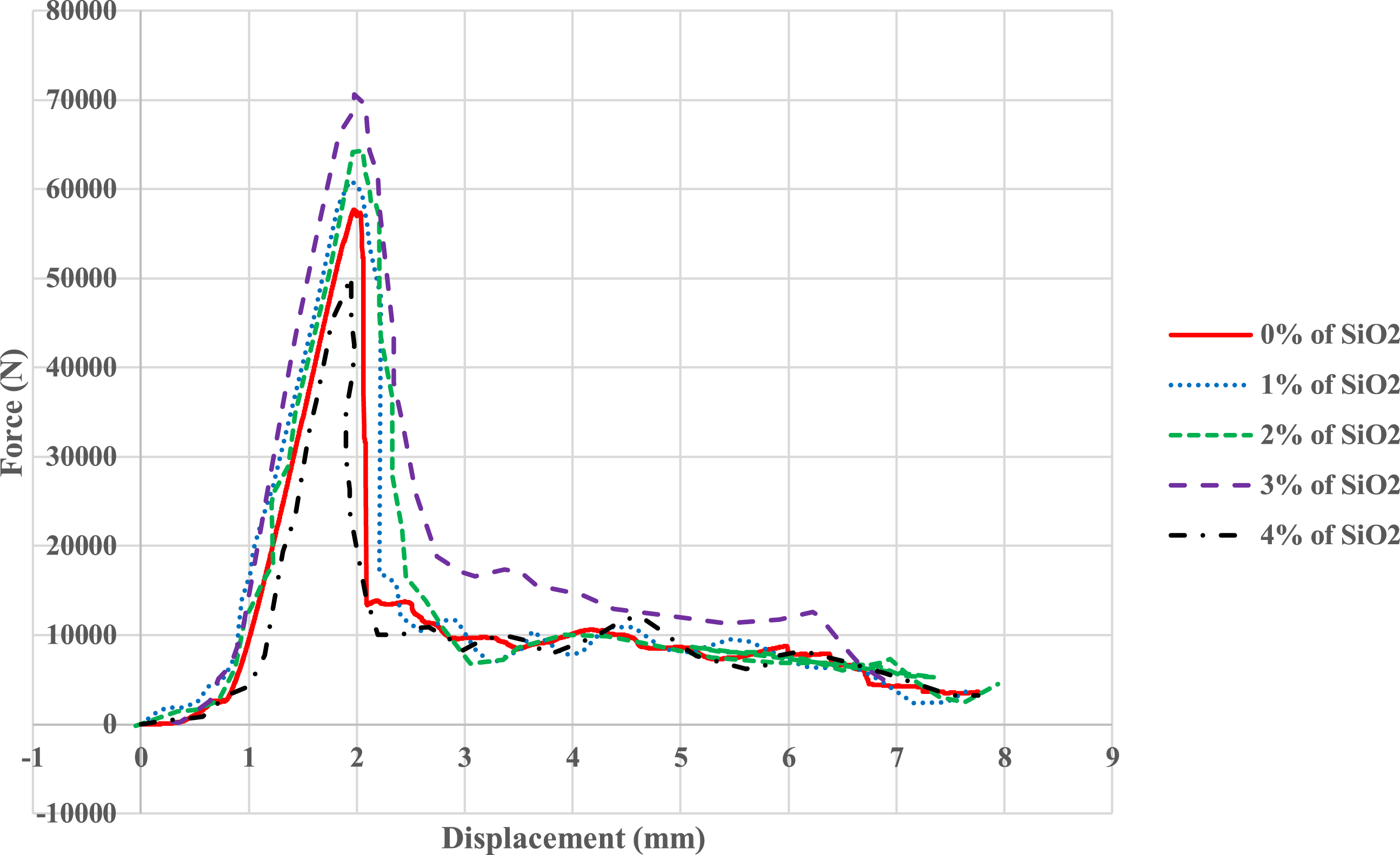
Effect of M-shaped design on the compression strength of sandwich panels
All tests started from a preload which is the starting point that this preload allows the structure to increase the resistance against sudden failure. In other words, this preload warms up the structure to hold on to a more significant compression load. In the next step, the structure enters into the second mode, in which elastic modulus works, which assists lead structure to a higher level of compression load. After that, the failure of the upper face sheet starts at the same time. M-shaped core tries to hold on to the structure in the regular stage and resist failure. As can be seen again, after the failure of the upper face sheet, M-shaped core starts to resist. Then, the second ultimate buckling load happens where the bottom face sheet and M-shaped core resist the second failure. In this time, the effect of nano-silica and M-shaped core are significant. After studying the failure factors in this structure, the delamination in face sheets and failure inside beams in M-shaped core can be estimated as primary factors of failure. However, as can be seen in Figure 10, nano-silica will play a healing agent which by constituting the chain structure in micro-cracks, tried to resist unexpected failure, which the healing characteristic of nano-silica is undeniable.
Also, the compression strength of the sandwich panels can be explained according to this graph. As mentioned before, all the specimens are similar under the buckling loads. The linear behavior of the structure is quite evident in this graph that relates to the initial resistance of the core to the applied stresses. Also, the linear part of the graph has been increased dramatically as the amount of nano-silica increases and brings the ultimate strength point to a higher level. The early part of the force-displacement diagram (Figure 10) shows a linear increase because the cell wall deformed linearly until it reached the maximum force. At this maximum force and stress, the structure starts to buckle at the edge. After the maximum stress point, the value of stress decreases due to the strain increase. As a result, the geometry of the core and the nanoparticles simultaneously improved the sandwich structure’s compressive strength. These structural elements can offer greater structural efficiency due to their core design. Figure 12 shows the failure mechanism of sandwich panels with an M-shaped core. Deformation history and failure modes for compressive test.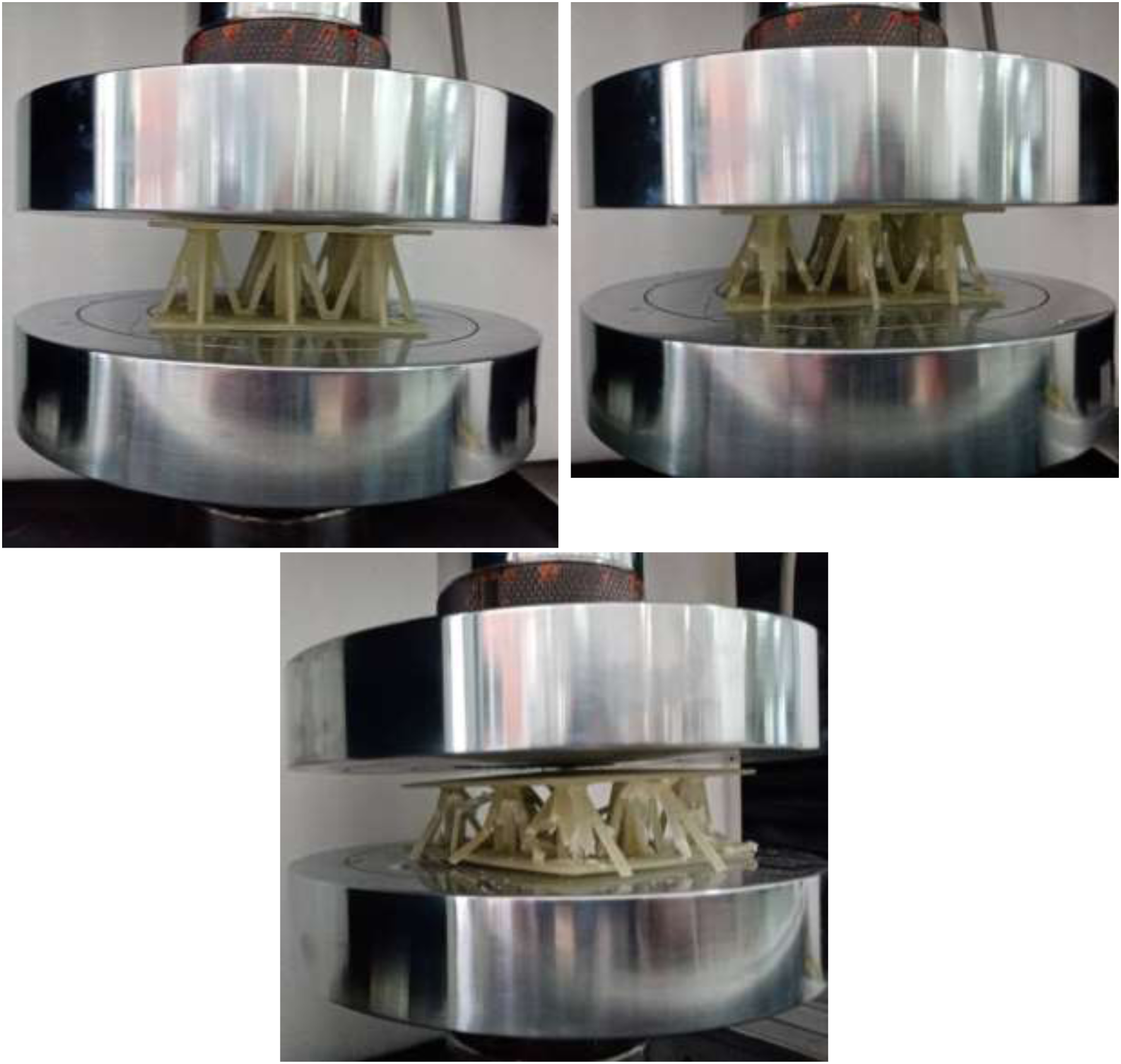
Results of three-point bending test
The flexural behavior of sandwich panels (foam-filled and foamless sandwich panels) is studied in this section. Three specimens were tested under three-point loading to failure step for each test. The force-displacement diagram for this test was obtained. The yield loads and ultimate loads for the sandwich panel with or without nano-silica and foam-filled were compared to investigate the effect of M-shaped design, nano-silica, and PU-Foam on the flexural behavior and collapse of the structure.
Effect of nano-silica on the bending strength of sandwich panels
To investigate the effect of nano-silica on the ultimate strength of specimens, the force-displacement diagram obtained from the bending test is studied (Figure 13). By examining the following diagram, it can be obtained that results are similar to those of the tensile and compressive tests, in which the samples containing 3 wt. % silica had the highest bending strength and the addition of 1–3% silica improved the flexural properties of the composite. However, the addition of 4% nano-silica dramatically reduced the amount of compressive force to an even lower level than the neat state (0 wt. % of nano-silica). In 1 wt.% and 2 wt.% nano-silica samples, the distance between the dispersed nanoparticles between fibers and epoxy is greater than in 3 wt.% nanoparticle samples. And in the 3 wt.% nano-silica samples, this distance is reduced and the nanoparticles can prevent the growth of cracks more, thus delay the failure of the samples and the samples show more resistance. The results of the present study show that by adding from 1 to 3 wt.% of nano-silica, the strength of the samples had a significant upward trend and has reached a maximum value for 3 wt.% of nano-silica. However, adding more than 3 wt.% of nano-silica causes porosity and crack growth in the samples, which results in weakening and faster failure in them. Also, by adding more than 3 wt.% of nano-silica to the epoxy resin, the viscosity of the epoxy is greatly increased and it does not spread evenly between the fibers and high viscosity is created in it, and this problem causes weaker and faster failure of samples containing more than 3 wt.% nanoparticles. Force-displacement graph obtained from three-point bending tests.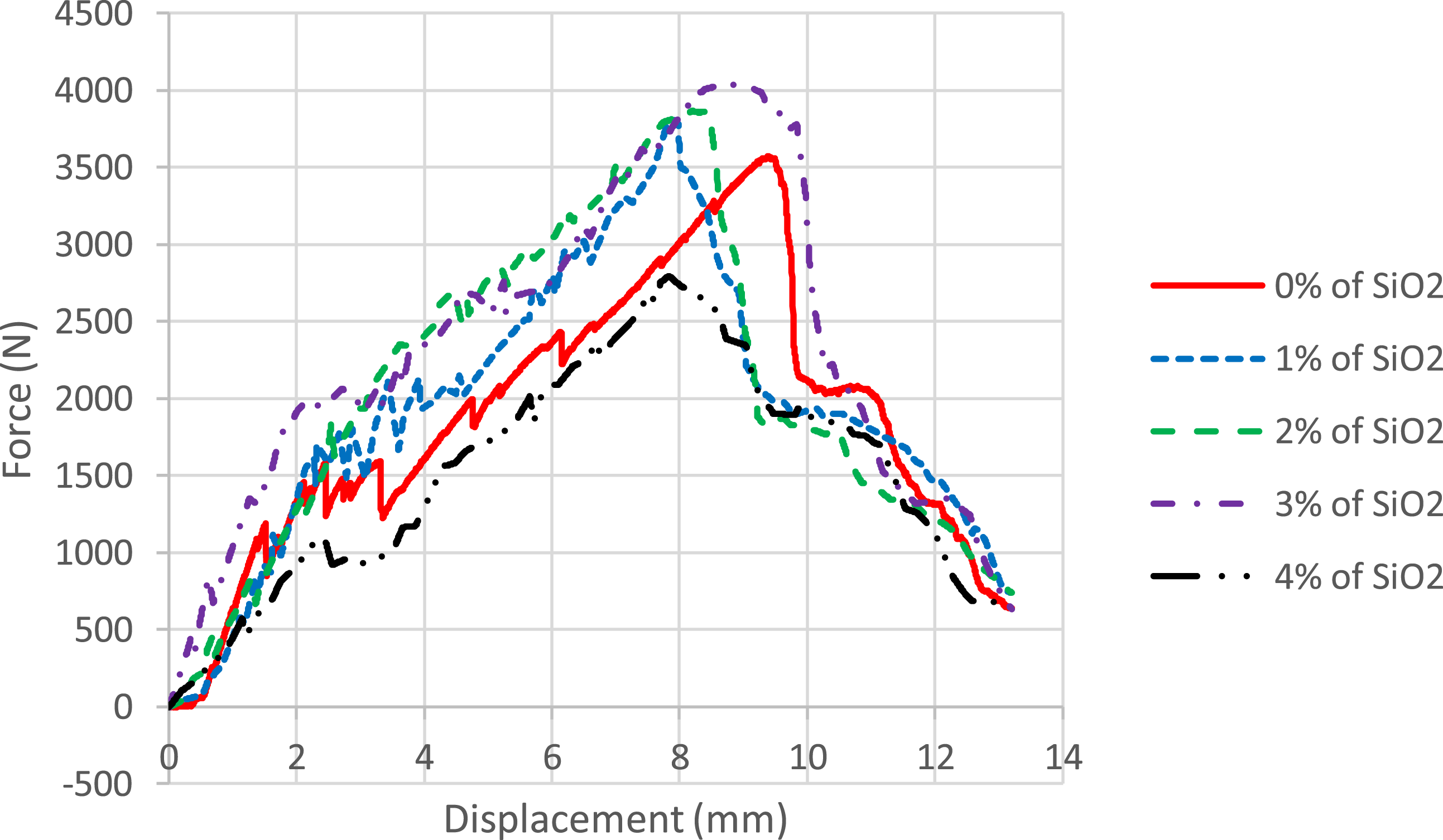
This can be explained by the bending strength of nano-silica that play as a nano-filler. Also, by citing the SEM pictures (Figure 14), the nano-silica with good diffusion between the matrix particles could distribute the stresses throughout the structure and significantly prevent failure. SEM pictures of samples after bending test.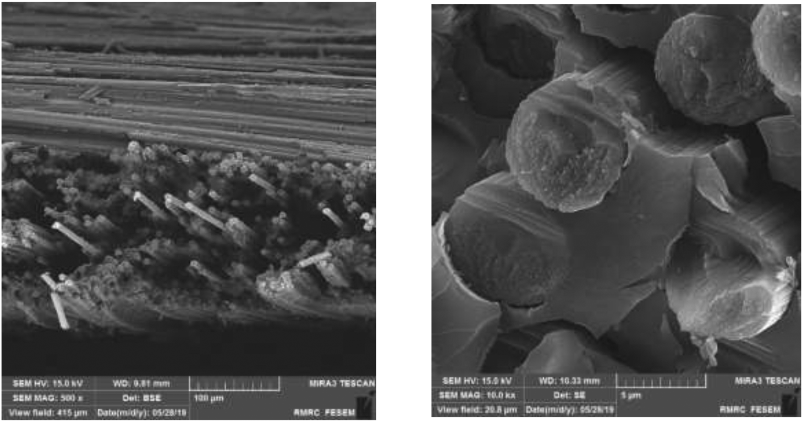
Effect of M-shaped design
Figure 15 shows the deformed shape of the sandwich panel after the peak load of the bending test. As predicted, both the face sheets and the core parts under the apply load (middle of the specimen) failed due to the local buckling. As the core separates from the faces, the core’s component begins to collapse along the same path, and then it extends to the edges of the panel. Note that the buckling occurred only in half of the length at the beginning of the test, and the core’s joints did not break until the applied load increased and reached the ultimate point. After the maximum strength point, M-shaped joints buckled and continued to deform, with the load level decreasing as the compression proceeded. The M-shaped design helped the sandwich panel delay the deforming of the core component that increased the bending strength of the panel and also, some of the core parts remained unchanged after the test. A Sandwich panel with an M-shaped core has a tremendous bending failure point due to its engineering design. In other words, the beam of this core has a significant role in withstanding the force of failure. Deformation history and failure modes for three-point test.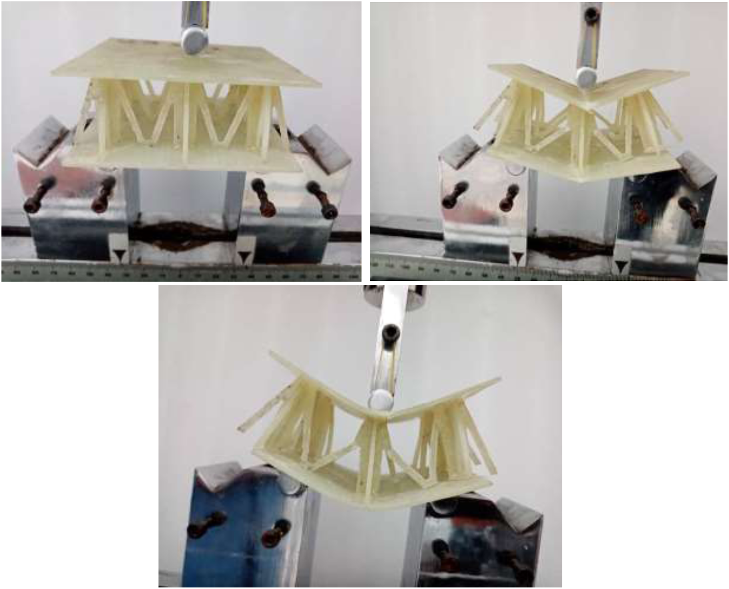
Results of flexural test for foam-filled sandwich panels
In this section, the compressive and three-point bending tests were performed for the foam-filled sandwich panels. For this purpose, specimens were quite similar to those used in the preceding sections, compression and three-point bending tests, and only filled with PU. Figure 16 shows the foam-filled specimens under the compressive and three-point bending tests. Foam-filled sandwich panels under (a) compressive and (b) three-point bending test.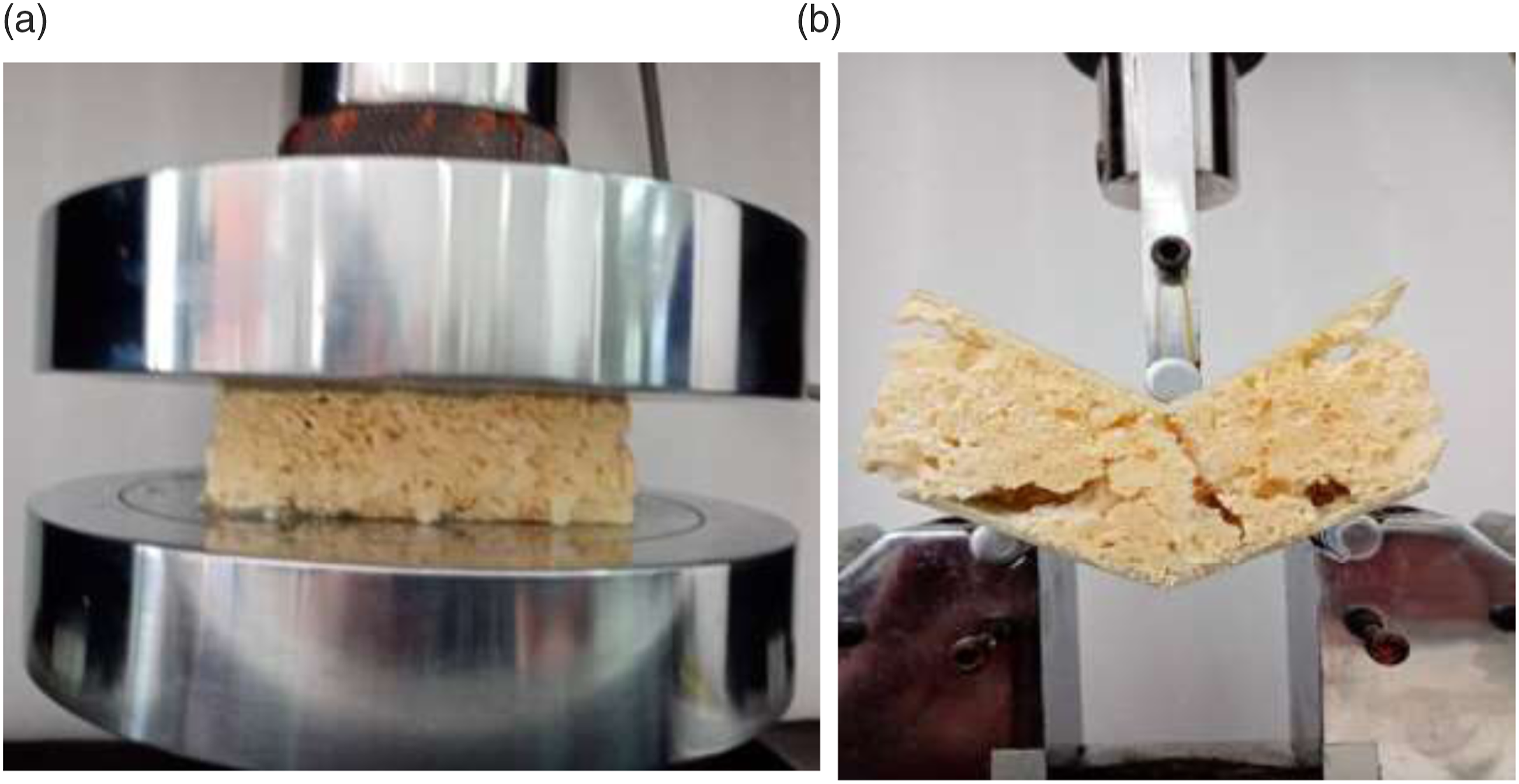
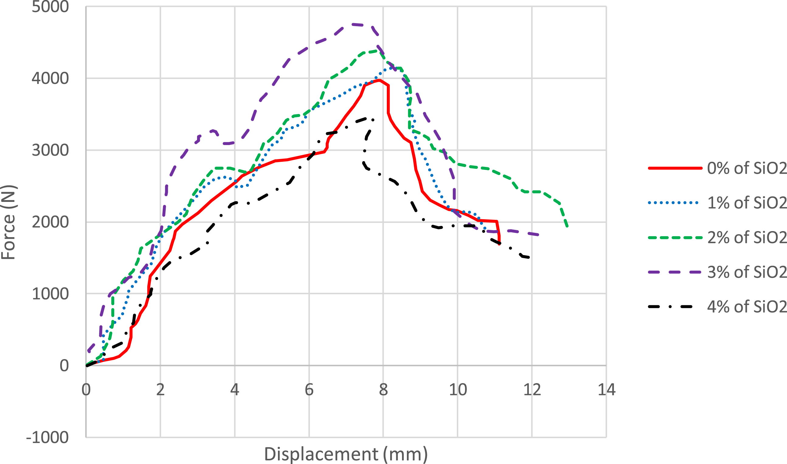
Figures 17 and 18 are the force-displacement diagram obtained from the compressive and three-point bending tests, respectively. As seen in both of the tests, nano-silica significantly affected the flexural and compressive strength of the foam-filled samples, the same as the samples without foam. However, by comparing the foamless and foam-filled sandwich panels in both tests, the relative increase in flexural and compressive strength of the foam-filled specimens was evident. The amount of energy absorbed is obtained from the area surface of the bellow force-displacement diagram. The M-shaped core of the sandwich panel acts as an absorber and absorbs significant energy. Therefore, it can be concluded that these types of adsorbents have high energy efficiency. Sandwich energy absorbers with lattice core have symmetric and homogeneous collapse mechanisms in the core due to their structural shape. Also, the initial maximum force in this type of adsorbent is small and close to the average force. The foam had the effect of stabilizing core member buckling for the foam-filled sandwich panel, resulting in much enhanced compressive strength relative to the empty panel. It indicated that the plastic formation of the core in the foam-filled panel was significantly delayed as a result of the lateral support provided by the foam to the core members against plastic buckling. Also, M-type cores, nano-silica, and PU foam had a synergistic effect on sandwich panels' flexural and compressive behavior. Force-displacement diagram of the foam-filled sandwich panel under the flatwise-compression test. Force-displacement diagram of the foam-filled sandwich panel under the three-point bending test.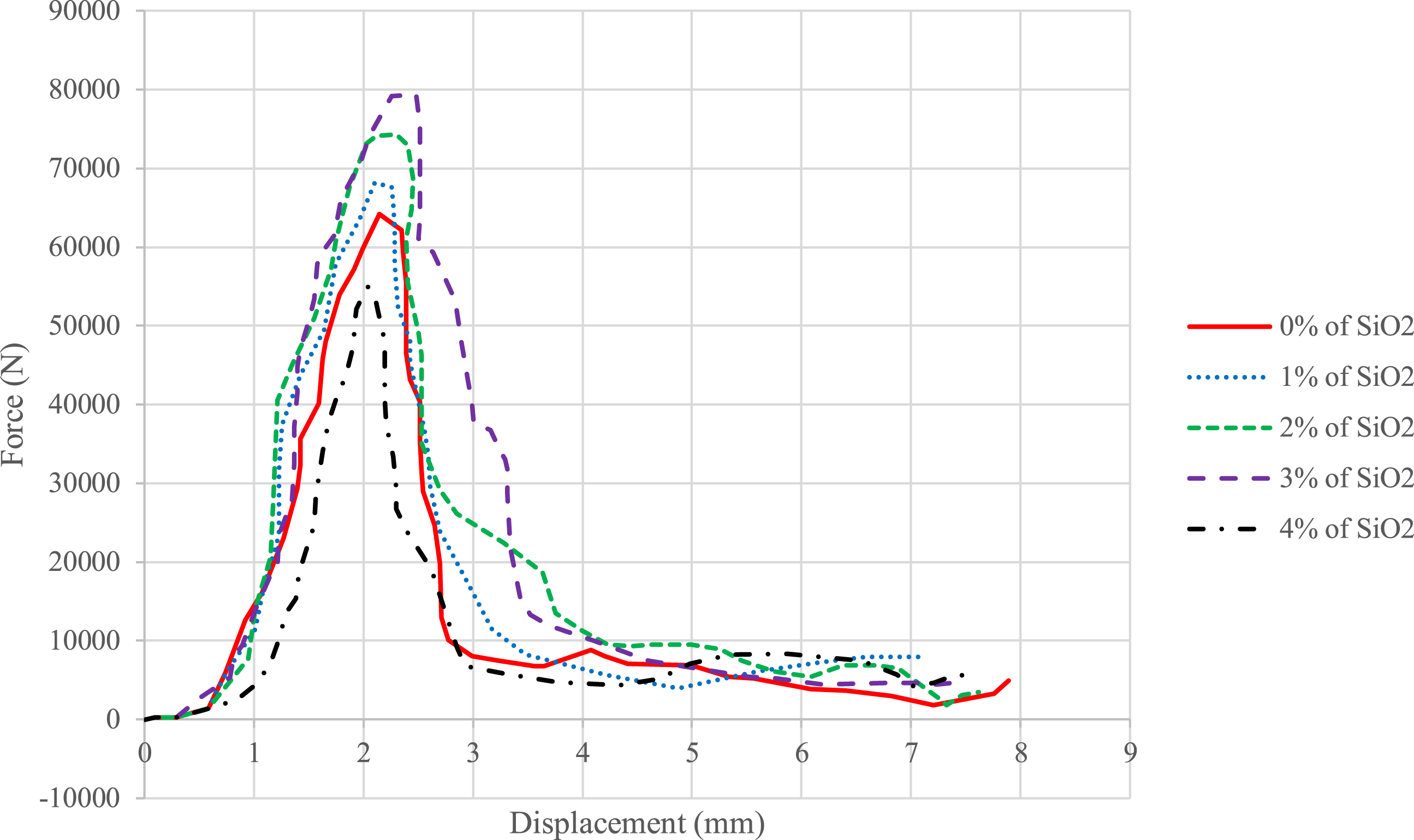
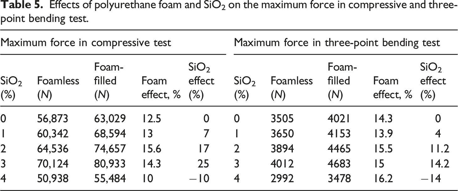
Effects of polyurethane foam and SiO2 on the maximum force in compressive and three-point bending test.
Conclusion
In this paper, the foam-filled and foamless sandwich panels were designed and fabricated to evaluate the flexural and compressive strength of the all-composite sandwich panels with a novel M-shaped core. Afterward, flatwise compression and three-point bending tests were performed. All the specimens were prepared with eight layers of GF/epoxy laminates. A water jet machine cut the faces and the M-shaped core with the specific size and geometric dimensions and then the sandwich parts were assembled with epoxy adhesive. Silica nanoparticles were added to epoxy matrices in four different weight percentages of 1%, 2%, 3%, and 4% to obtain the optimum value of mixing ratio of silica and epoxy due to enhance the mechanical strength of laminates and sandwich panels. Also, PU foam was injected among the core to investigate the energy absorbing and compressive strength of the sandwich structure and deformation mechanism of the cores. SEM pictures were used to identify the dispersion of the silica nanoparticles in the epoxy matrices. The final results showed that the flexural properties of the GFRP Sandwich panel increased significantly by adding 2–3 wt% of silica nanoparticles to the epoxy. The new design of core (M-shaped) can postpone the buckling and failure of sandwich structures. On the other hand, scientific shape and all M-shaped dimensions played a wise role in the case of resistance. Moreover, injecting the PU-Foam among the core enhanced sandwich structures’ ultimate buckling load and absorber features.