
Abstract
Increased lightweight design via composite sandwich structures is a promising approach due to their exceptionally high weight-specific mechanical properties. The involved high cost when using sandwich composite structures has hindered applications in cost-sensitive markets up to now. However, full thermoplastic composite sandwich structures enable a cost reduction using novel processing routes based on fusion bonding of core and facesheet. In order to optimize such full thermoplastic composite sandwich structures and to ensure proper bonding of facesheet and core after manufacture, valid test methods for the quantification of skin-core interfacial bonding are required. This paper reviews existing test methods for the determination of Mode I dominant interfacial fracture toughness of sandwich structures. The main focus is set on cantilever beam tests as well as on peel tests. Based on a definition of requirements for suitable test methods, their applicability for full thermoplastic composite sandwich structures is evaluated. The Mandrel Peel Test results as most promising test method for thermoplastic sandwich structures, especially with thin facesheets.
Keywords
Introduction
Lightweight design plays an increasingly important role in modern transportation, due to growing energy efficiency requirements. The electrification of cars is a popular example. In order to meet more and more rigorous CO2 emission limitations of car fleets, the share of battery electric vehicles will grow if automotive companies want to avoid drastic financial penalties. 1 The traction battery however introduces several 100 kg of weight to the car, and despite simplifications of the electric drivetrain compared to internal combustion engine (ICE) vehicles in general, it leads to a significantly increased car weight as observed in modern battery electric vehicles (BEVs). For this reason, different approaches have been developed to reduce the mass of BEVs, such as the extensive use of carbon fibre reinforced plastics in BMW i3 and Polestar 1, yet with high costs involved. In order to increase cost-efficiency, thermoplastic composites are a promising candidate and a variety of different thermoplastic composite components have been developed and introduced in automotive applications using novel processing methods.2–5 In order to further increase lightweight design of cost-efficient thermoplastic composites, full thermoplastic sandwich structures and process methods have been of interest by different researchers due to their high weight-specific mechanical properties. For this reason, a number of different thermoplastic-based sandwich composite structures and processing techniques have been developed in recent years.6–24
Sandwich structures in principle consist of a three-layer cross-section with a core and two covering facesheets. 25 The resulting composition is similar to an I-beam structure with a clear division of tasks between facesheets and core, following the stress distribution in the cross-section induced by bending loads. 26 The facesheets carry the majority of the normal stresses. Contrary, the core shall bear mostly the transverse shear stresses between the facesheets and support the factsheets at compressive loads in thickness direction. 27 In addition, the core leads to an increase of the second moment of area due to its thickness, resulting in an over-proportional growth of the flexural rigidity.28,29 The relatively low stress levels in the core compared to the cover areas of the sandwich cross-section, enable using a core material or structure with low-density. 30 This significantly increases material and weight efficiency of the sandwich structure, making those structures interesting for many lightweight design applications. 31 As discussed, the covering facesheets of sandwich components need to provide high mechanical properties. For this reason, metal and continuous fibre reinforced plastics (CFRP) are commonly applied. 32 Regarding the latter, a shift in polymer materials used can be observed. For decades, CFRP facesheets for sandwich structures have been based on thermoset matrices such as epoxy. 32 However, composite sandwich structures based on thermoplastic polymers are increasingly investigated, early examples are the works of Åström and Akermo33–35 in the late 1990s among others. The reasons for this trend are the beneficial properties that thermoplastic polymers offer against thermosets. Brittle mechanical behaviour and limited debonding resistance of thermoset composite facesheets are major challenges.13,36 Furthermore, the production of thermoset sandwich composites is time- and cost-intensive.8,9,20 This is because even advanced manufacturing techniques for thermoset composites such as high pressure resin transfer moulding (HP-RTM) or wet compression moulding are directly depending on the curing time of the resin, defining the composite manufacturing cycle and the processing sequence. This makes thermoset sandwich composites less attractive for cost-sensitive high-volume applications. In contrast, sandwich structures with thermoplastic composite facesheets and thermoplastic core, referred to as full thermoplastic sandwich, can be considered superior compared to their thermoset-based counterparts with respect to the aforementioned issues. If facesheets and core are based on the same polymer, processing techniques based on fusion bonding can be applied, which offer the potential to produce sandwich composite structures much more efficiently than with thermoset systems. In addition, this single-polymer sandwich design provides largely improved recyclability properties.9,10,13
Generally, it is essential for sandwich structures that the facesheets are properly bonded to the core, as bonding of facesheets and core (referred to as skin-core bonding) is fundamental to enable the full mechanical potential of sandwich structures. 28 Moreover, loss of skin-core bonding leads to the loss of structural integrity of the whole structure and ultimately to its total failure.37,38 In order to evaluate and optimize the interfacial bonding behaviour, different testing methods have been developed within the past decades focussing on the interfacial fracture toughness as strain energy release rate (SERR) during crack initiation and propagation. Although there are very promising candidates, no specific test methods for the determination of interfacial fracture toughness of composite sandwich structures have been standardized yet contrary to monolithic composites. 39
This is even more true for full thermoplastic sandwich structures, which introduce specific requirements to interfacial bonding testing. As thermoplastic matrices are often more compliant than thermosets and as some exhibit unipolar characteristics, respectively, load application to the specimens may be challenging. To the knowledge of the authors, little to no comprehensive research was performed on the applicability of test methods for the evaluation of skin-core bonding of full thermoplastic sandwich structures. To fill this gap, this paper provides an overview of existing test methods for evaluating interfacial fracture toughness. Based on a definition of requirements for suitable and valid test methodologies, a comprehensive evaluation of the applicability as well as limitations of specific test methods for full thermoplastic sandwich structures is presented.
Requirements for test methods
For an evaluation of test methods for applicability at full thermoplastic sandwich structures, evaluating criteria and requirements need to be established first. In his work, Ratcliffe
40
defined requirements for a standardized test method enabling the evaluation of Mode I dominant skin-core crack resistance of sandwich structures in general, leading to the Mode I fracture toughness referred to as (1) Complexity of the test apparatus and procedure must be minimized (2) The data reduction method used for computing (3) Specimen loading must be Mode I dominated, and this condition should be insensitive to debonding length (4) The test must result in debonding growth either at, or in the vicinity of the facesheets/core interface, parallel to the plane of the interface. (5) Debonding growth must be stable, although stick-slip growth may be permitted (6) Specimen response must be linear elastic and must be appropriate for analysis using linear elastic fracture mechanics (LEFM). (7) The test must result in the measurement of quasi-static values of Gc, including an initiation value and subsequent propagation values. (8) It must be possible to test a practical range of sandwich systems including structures with compliant composite facesheets.
The first requirement attributes to an intended high working efficiency of the test methods. If the specimens and test methods can be prepared and conducted in a quick and reliable way, more tests can be performed and more data can be generated. Moreover, data generation and evaluation during testing such as video assisted crack tip assessment should be kept as simple as possible, as complex test performances are prone to inaccuracies and mistakes. The second requirement addresses the calculation of the desired test methods results. Different data reduction methods have been developed taking into account different material and test specific constraints. In order to reduce data reduction complexity and hence possible inaccuracies, simple analytical approaches are favourable. The next requirements address the process of debonding of sandwich structures. It is general consensus, that the most critical opening mode at the tip of a skin-core crack in sandwich structures is Mode I.41–44 For this reason, a Mode I dominated test method shall be found (Requirement III). In addition, the crack is required to propagate at or in the very vicinity of the skin-core interface (Requirement IV). Crack propagation shall occur in a stable manner, though the frequently observed slip-stick behaviour of debonding interfaces is also accepted (Requirement V). The structural behaviour during testing should be linear elastic enabling the use of linear elastic fracture mechanics (LEFM) (Requirement VI), which builds the basis for the calculation of the SERR at crack initiation and propagation 45 (Requirement VII). The last requirement that Ratcliffe 40 presents is that the test method should enable using sandwich structures with different materials and geometries (Requirement VIII) in order to be able to optimize sandwich structures and to quantitatively compare their skin-core bonding characteristics. A further specification of this last requirement is made here for the specific application of very thin thermoplastic composite facesheets, which may suffer excessive bending during testing due to their low intrinsic flexural rigidity. This may result in fibre kinking and fibre damage of the facesheets, especially in the vicinity of the load introduction area. 46
After the definition of requirements for evaluation, the most promising candidates for Mode I dominant testing of skin-core interfacial bonding of thermoplastic sandwich structures will be presented and critically discussed in the following segments. The selected group of test methods comprises interfacial fracture toughness test methods as well as promising peel test methods.
Interfacial fracture toughness test methods
The theoretical analysis of the crack propagation along an interface between dissimilar materials has been of great interest for researchers for decades, beginning with the work of Williams.
47
In this work, he studied the distribution of stress around a crack at the interface between two dissimilar and homogeneous isotropic materials, such as layers of differing rock material or welded joints. This was followed by the analytical calculations of stress intensity factors at dissimilar material interface cracks by Erdogan,
48
Rice
49
and England,
50
all published in 1965. Experimental analysis of interfacial cracks of layered structures and of sandwich structures in particular followed only later. Experimental analysis of the interfacial skin-core bonding of sandwich structures mainly determine the SERR as measure of crack resistance during the debonding of facesheet from core.40,51 Without claims of completeness, the most common test methods are presented according to the opening Mode: 1. Mode I: (a) Double cantilever beam (DCB) (ASTM D 5528
52
), (b) Single cantilever beam (SCB), (c) Peel tests. 2. Mode II and Mixed Mode: (a) Tilted sandwich debond (TSD), (b) Modified three-point bending (MTPB), (c) Cracked sandwich beam (CSB), (d) End notch flexure (ENF).
The focus of this paper lays on Mode I fracture toughness test procedures, considering Requirement III (Mode I dominance). However, even those test methods providing a global Mode I loading of the interface between core and facesheet may include a Mode II component when applied at sandwich structures. According to Hutchinson and Suo,53–55 this is due to the asymmetry of material properties of core and facesheets as well as of the loading condition during testing. This incorporation of a Mode II component hence leads to a combination of Modes, which can be expressed as Mode Mixity Phase Angle or Mixed Mode Ratio. 56
Most Mode I dominant test procedures can be mainly grouped into DCB and SCB test variants. 40 This paper will hence focus on these test methods. In addition, peel test methods will be evaluated, as they show promising characteristics for the SERR determination of layered material combinations such as sandwich structures. In the following sub-chapters, the DCB and the SCB as well as variants thereof are presented and critically discussed. After these sections, an overview of promising test methods based on peel testing methodologies is given. This main section ends with an overview of a test method specific evaluation regarding their applicability for ski-core bonding of full thermoplastic sandwich structures based on the defined requirements.
Double cantilever beam
One of the most popular examples of Mode I fracture toughness test methods for polymer composites is the double cantilever beam (DCB), as standardized in ASTM D 5528.
52
The test method originates in the work of Obreimoff
58
for the evaluation of the splitting strength of mica. The test set-up was modified by Gilman
59
and is basically unchanged in ASTM D 5528 except for details regarding the load applications. Though originally developed for monolithic material architectures, the DCB set-up was adapted by Prasad and Carlsson
60
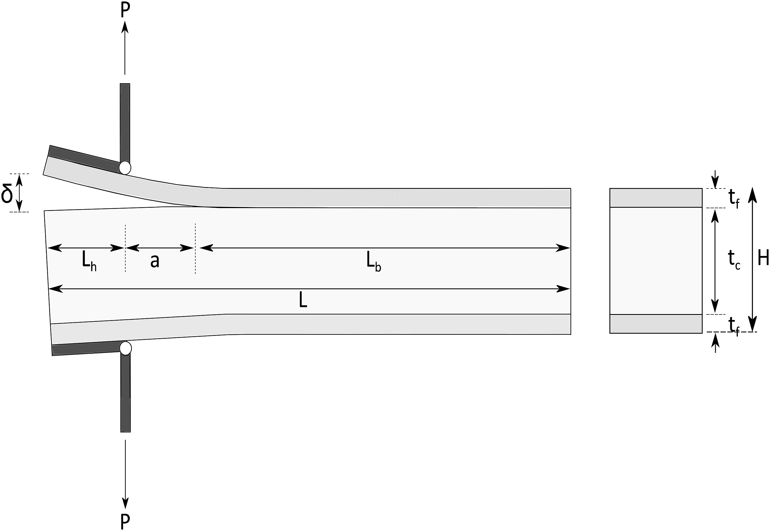
for sandwich structures. Contrary to the standard for monolithic composite structures, sandwich structures do not have the pre-crack in the middle of the cross-section height, but at the interface between core and upper facesheets, see Figure 1. Except for this difference regarding symmetry of specimen load application, the testing procedure is equivalent to the one for monolithic structures. The test method involves a load The double cantilever beam used for interfacial testing of sandwich structures: asymmetric crack location in thickness direction and load application using piano hinges, based on Ratcliffe.
40
During testing, the SERR can be assessed applying different data reduction methods.61,62 Without claims of completeness, they include the modified beam theory (MBT), 63 compliance calibration method (CC),64,65 compliance-based beam method (CBM) 61 and the elastic foundation analysis method (EFA),66–68 which was originally developed by Kanninen 69 for isotropic materials and extended to orthotropic materials by Williams. 70 These data reduction methods however are only valid if the requirements of LEFM are satisfied, including small scale deflections and linear elastic material behaviour. According to Ural et al. 71 who studied skin-core bonding of carbon fibre reinforced PMI sandwich structures with honeycomb cores, the DCB method meets these requirements.
For the calculation of SERR using these data reduction methods, the specimen width
A correction factor

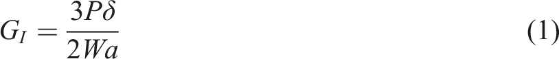
Here, Determination of the correction factor 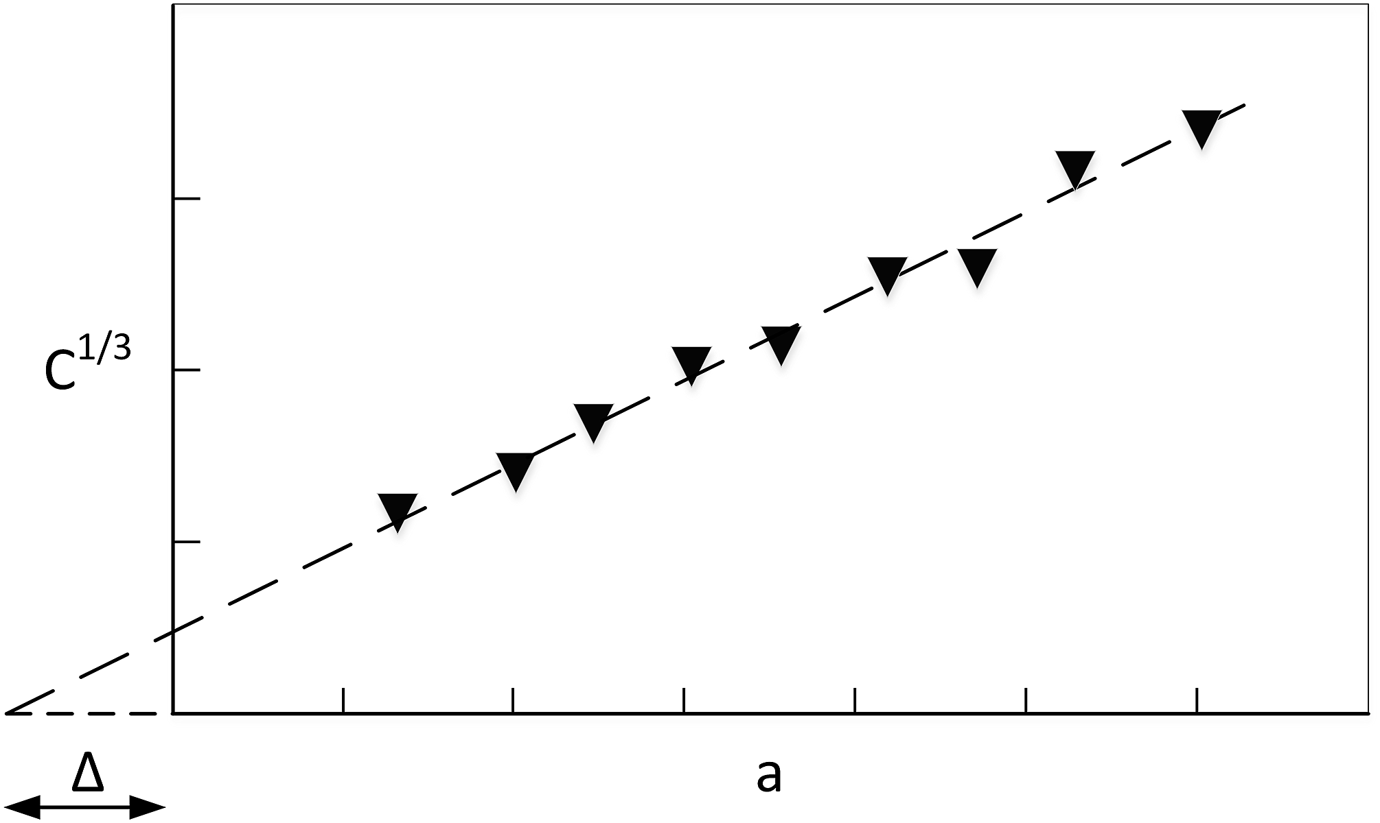
The correction factor

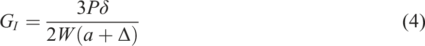
Integrating the effective crack length in equation (1) results in
During testing, the applied load and crack length plot shows two distinct stages of crack growth.
Despite all efforts to adapt the DCB method from monolithic materials to sandwich structures, challenges still exist. Firstly, the propagating crack during testing leads to an increasing rotation of the specimen around the bottom load application71,73,74 and bending moments develop in the core area resulting from the eccentric load application.
41
In addition to the test set-up induced difficulties, the results can be influenced by specimen geometry. According to Ural et al.
71
and their studies on sandwich structures with honeycomb cores and carbon fibre reinforced polyimide (PI) facesheets, the determined
The most significant negative finding however is that the DCB test method used for sandwich structures involves a non-negligible Mode II fraction.74,76 This can be attributed to the asymmetric load introduction and material properties.47,50,54 It is generally agreed that a bi-material interface such as the sandwich skin-core contact leads to the coupling of normal and shear deformations.47,48,54,55,57 Similar findings were published by Burlayenko et al., 77 who studied the debonding behaviour of sandwich structure with glass fibre reinforced epoxy composite facesheets and PVC foam cores using the DCB and SCB method. Experimental and finite element analysis showed that the SERR were significantly higher using the DCB method, which they attributed to considerable Mode II fractions involved. In addition, they found that shear stresses at the crack tip were likely to lead to crack kinking into the core. This finding is supporting previous publications, in which crack kinking at DCB specimens was observed, which was attributed to a positive shear stress at the crack tip.60,74,78 He and Hutchinson 79 described the conditions leading to the kinking of a crack between two brittle materials out of their interface. According to their work, the tendency of a crack kinking into the core is a result of positive shear stresses at the crack tip and the satisfaction of a balance of involved SERR. Based on the studies of Prasad and Carlsson,60,80 crack kinking into the core of a DCB sandwich specimen is increasingly probable with decreasing Young’s modulus and density of the latter. Hence, for a typical sandwich structure combination of a foam core with significantly lower modulus than the facesheet, this often leads to a crack propagation from the skin-core interface into the core.
Considering these findings and the comparison with the imposed requirements to suitable Mode I sandwich testing procedures based on the definitions by Ratcliffe, 40 the DCB is considered to be not suitable for Mode I dominated testing of the Mode I dominant fracture toughness resistance of the skin-core interface of full thermoplastic sandwich structures.
Single cantilever beam
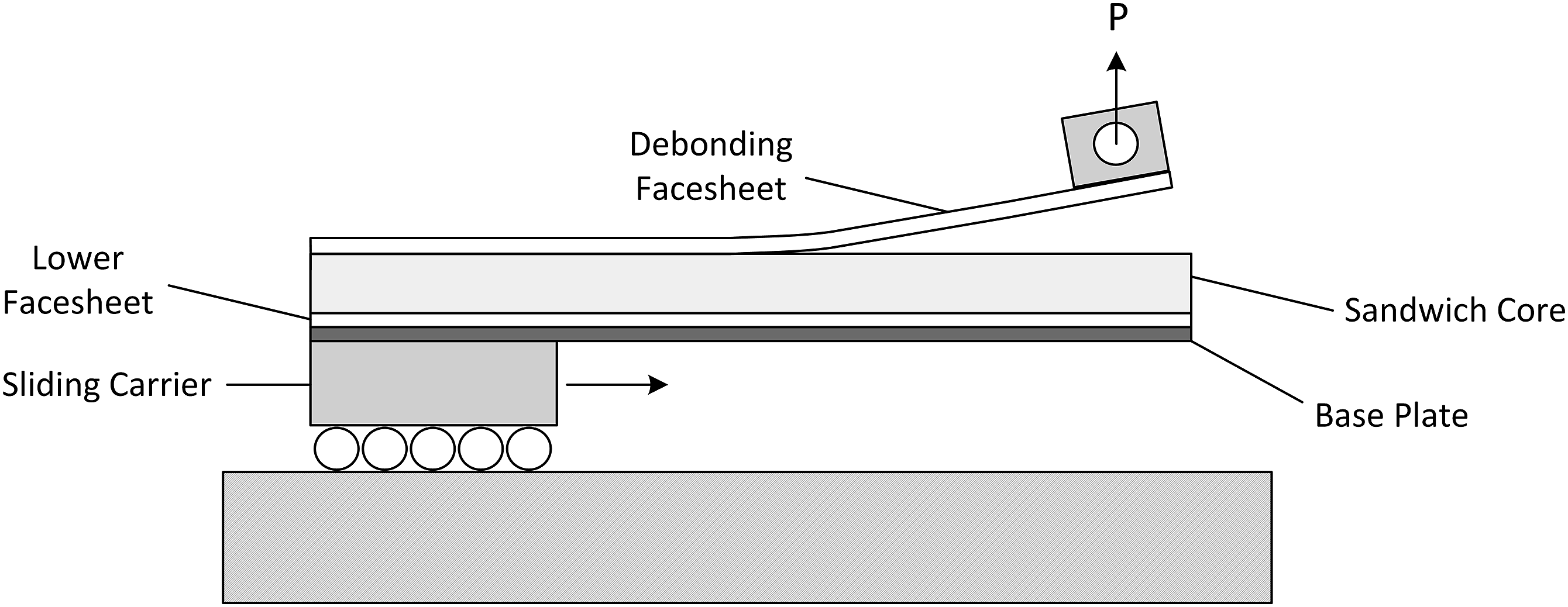
A variety of different SCB variants has been developed and studied, including SCB with different specimen fixations as well as introducing a varying peel angle using the Tilted Sandwich Debond (TSD) variant,81–84 which was first proposed by Grenestedt. 85 According to extensive studies by Adams and co-workers44,74,86,87 as well as Ratcliffe and Reeder,40,41 the SCB variant with the sandwich specimen fixed to a rigid base plate is most promising for determining a Mode I dominant fracture toughness of sandwich skin-core interfaces. For calculation of the SERR, data reduction methods can be applied equivalent to the DCB method. 83 In this specific variant, the lower part of the sandwich specimen is fixed to a rigid base plate avoiding bending and rotation, respectively, of the specimen, while the upper facesheet acts as cantilever beam that is peeled off the core via the introduction of a vertical load. However, since during the testing procedure the crack tip moves constantly, the load application is equivalently moving during testing which results in a varying test angle. This would lead to the development of shear stress in the core and a Mode II component at the crack tip depending on the angle at the crack tip.82–84,88 Consequently, measures are taken to enable a constant location of the crack tip with respect to the load displacement axis of the testing machine during the test. Two approaches are used in literature: the first makes use of a moving base carrier,37,83,84 whereas the other uses a long rotatable loading rod.40,41,88
Cantwell and Davies37,83 developed a single cantilever beam with a sliding carrier and steel base plate on which the specimen can be attached to, see Figure 3. A similar method was used by Glaessgen et al.
84
The horizontal movement of the base carrier makes sure that the load application only acts as vertical force, as any horizontal load components would lead to a movement of the carrier. Single cantilever beam with sliding carriage base plate avoids the variation of the peel angle, based on Cantwell.
83
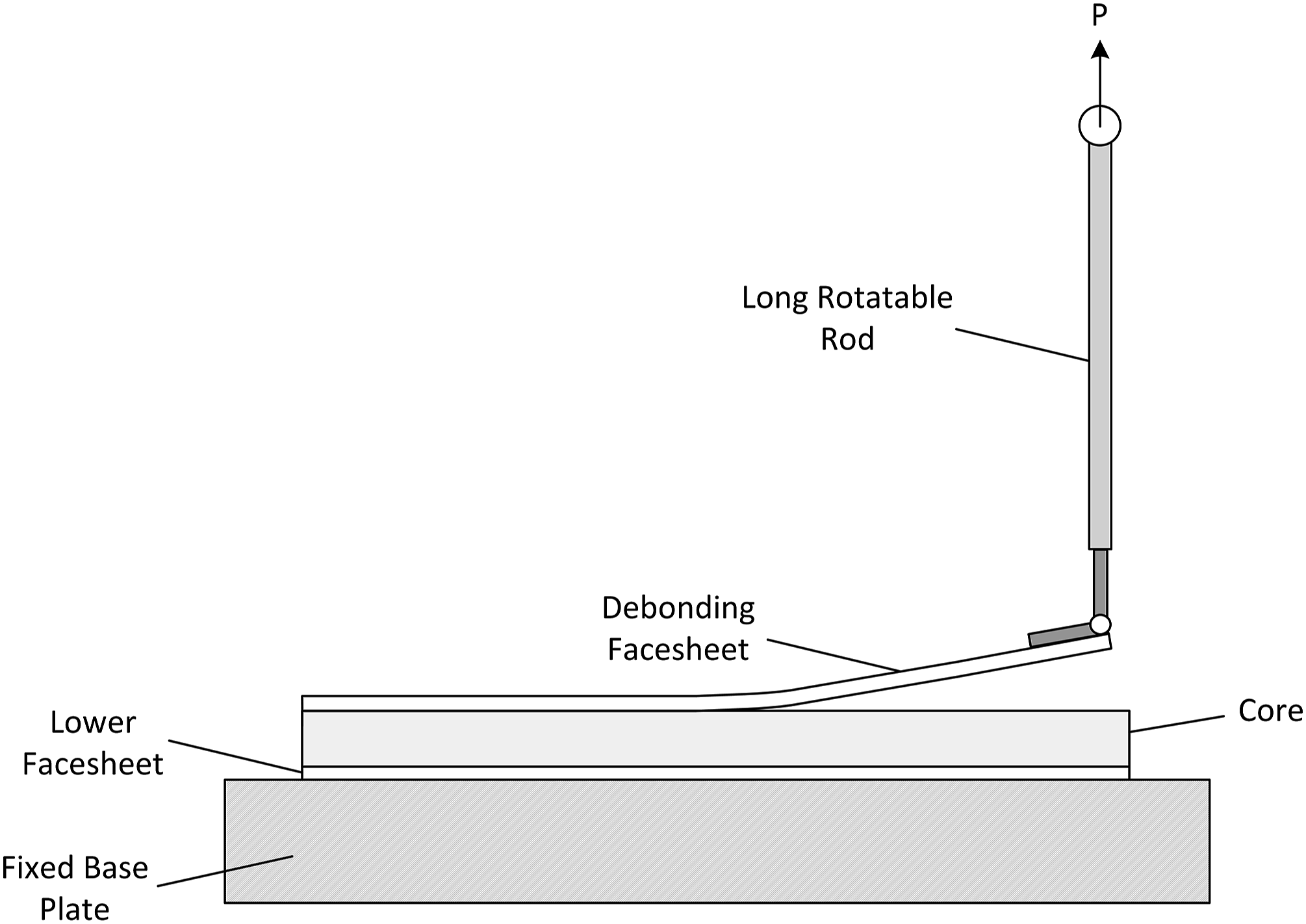
Another option to achieve nearly vertical load application throughout the testing is to use a long road connecting the specimen with the testing machine. McGarva and Åström 88 included a long rotatable rod that connects the testing machine and the hinge mounted on the facesheet for interfacial testing of sandwich structures with glass fibre reinforced polyamide 12 (PA12) facesheets and PMI foam core. Though they call their testing procedure modified DCB, it is actually a SCB method with specimens fixed to a rigid base plate. According to their test set-up, a rotatable long rod avoids the Mode II component and shear development in the core during testing, which was similarly proposed by Ratcliffe and Reeder in later publications.40,41
According to studies by Ratcliffe and Reeder
41
as well as Adams and co-workers,39,86,87 the use of a long rotatable loading rod leads to similar results compared to using a sliding base carrier while offering a much simpler test apparatus. They propose the SCB with long rod for application and standardization, respectively, in interfacial bonding testing and assessment of Mode I interfacial fracture toughness of sandwich structures, see Figure 4. There are several reasons for this. First of all, the SCB used for sandwich structures enables a significantly more Mode I dominant failure compared to DCB testing.73,77 Weaver
76
as well as Adams and co-workers39,44,74,86,87 published studies in which different test methods for interfacial fracture toughness testing of sandwich structures are directly compared with respect to the Mode I dominance and the crack kinking phenomenon. In a first study, they compared the DCB, a modified DCB, the Three Point Flexure (TPF), the SCB with cantilever beam support and the SCB with fixed base plate. According to their studies, the SCB with fixed base plate is Mode I dominant with minor fraction of Mode II due to shear stress at the crack tip leading to a Mode I fraction of more than 95%. Also, the Mode I dominance was found independent of the crack length and almost independent of facesheet thickness.74,87 Similar results indicating a clear Mode I dominance using the SCB method were found by Burlayenko et al.,
77
who studied the Mode I dominance of DCB and SCB test methods for sandwich structures with different material and geometry parameters. According to their results, the SCB is clearly more suitable to enable a Mode I dominated failure during testing compared to DCB. In addition to its Mode I dominance, the SCB method exhibits only a minimal tendency of crack kinking into the core, which was found by several authors.39,78,83 Burlayenko et al.
77
even established a negative shear stress at the crack tip using the SCB method, which would result in a crack propagation towards the actual skin-core interface or even to the facesheet. In order to provide consistent and reproducible SCB test method variant with long rotatable rod, based on Ratcliffe and Reeder.
41
Despite the discussed positive characteristics of the SCB with fixed base plate, some issues still exist. Variations of sandwich materials may influence the results of the calculated
Peel tests
Other test methods for the assessment of interfacial bonding of sandwich structures originate in the determination of the peel strength of metal-metal bonds, which was first proposed by Spies.
92
In addition to metal-metal bonds, a large variety of other material combinations has been developed that require interfacial bonding evaluation. According to Moore,
93
bonded material combinations can be grouped according to their principal mechanical behaviour into: (1) Flexible-flexible, (2) Flexible-rigid, (3) Rigid-rigid.
Rigid-rigid material combinations include structures of welded thermoplastic composites,94–96 hybrid structures consisting of a composite reinforced metal substrate97–101 as well as adhesively bonded metals.102,103 Flexible-rigid combinations include the combination of an adhesive on a rigid, typically metal substrate 104 or a thin layer on a thicker substrate, such as coatings105–107 or printed circuit boards. 108 Flexible-flexible material combinations typically include packaging and multi-layer foils, respectively.109,110
For the testing of interfacial bonding of these material combinations, a large variety of peel tests and variants has been developed in the last decades. Standardized and widely adopted test methods include: (1) Floating Roller Peel (FRP) (ISO 4578,
111
DIN EN 1464,
112
ASTM D 3167
113
), (2) 90° Peel Test (ASTM D 6862,
114
ASTM D 3330,
115
DIN EN 28,510–1
116
), (3) 180° Peel Test (ASTM D 3330,
115
DIN EN ISO 8510–2
117
), (5) Climbing Drum Peel Test (CDP) (ASTM D 1781
120
), (6) Mandrel Peel Test (MPT).
These tests usually evaluate the force needed to peel the top adherent off the substrate and put it into relation with the interface contact area resulting in a peel strength. The peel strength however can be translated into a fracture toughness based on an energy balance analysis of the respective peel method, if the dissipative energy fractions can be validly considered in the energy balance.
121
This makes them promising for possible use as Mode I dominant test method for thermoplastic sandwich structures. Nevertheless, some of the peel tests do not directly control the bending radius of the bending arm during peel testing, see Figure 5. This does not comply with the last requirement for suitable interfacial bonding test methods for composite sandwich structures with thin facesheets. Using these test methods, invalid failure due to the introduction of fibre damage may occur in the bending arm, that is, the composite facesheet of the sandwich structure.
122
Free peel test (left) and roller-assisted peel test (right), based on Kawashita et al.
124
For this reason, only peel test with means to limit and control the bending radius will be considered in this paper for applicability at full thermoplastic sandwich structures, that is, the climbing drum, floating roller and the mandrel peel test.
Climbing drum test
The climbing drum peel test (CDP) was first standardized as ASTM D 1781
120
in the 1960s. The test method is often applied for testing the delamination resistance and skin-core bonding of sandwich structures, respectively,124–128 also for thermoplastic sandwich structures.
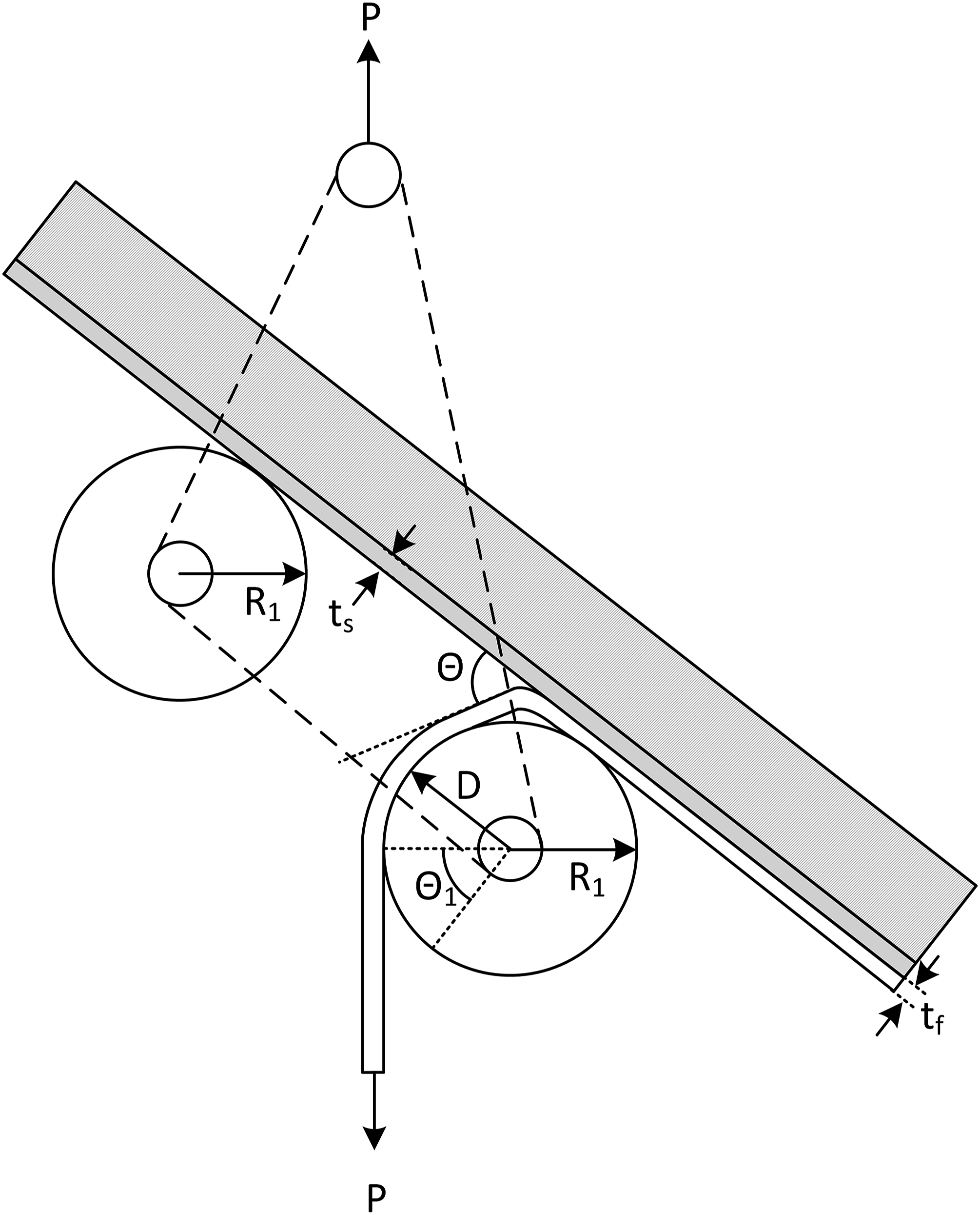
129
The test procedure begins with the fixation of the upper sandwich facesheet to a drum, see Figure 6. This drum exhibits two sections with different radii. The facesheet is attached to the inner section with radius Climbing drum peel test principle, based on Nettles et al.
124
In its standard version, the climbing drum method yields a peel strength, that is, a force per width, and only enables a quantitative comparison of test results if the geometry is unchanged.
130
A study by Nettles et al.
124
however presents a method to determine the SERR using the CDP based on the work of Okada and Kortschot.
131
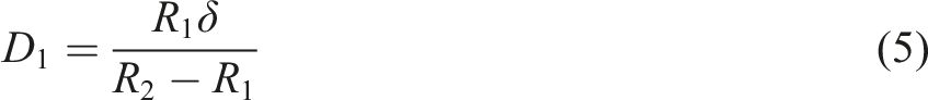
Due to the kinematic constraints, the crack length during testing
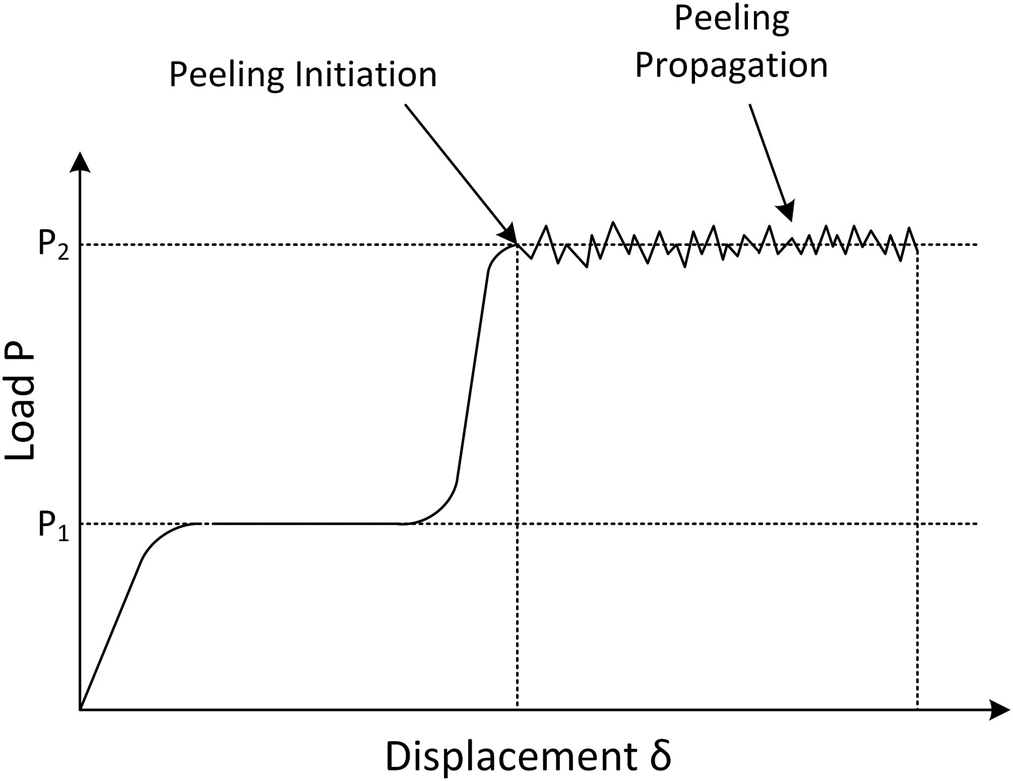
During debonding, two load stages can be observed.124,130 First, the facesheet is pulled around the centre drum with radius
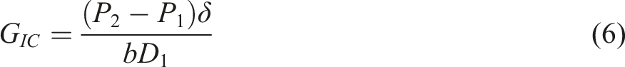
The grey area in Figure 7 denotes the work for skin-core debonding during the climbing drum peel test. Nettles et al.
124
translated the work for peeling into a critical strain energy release rate Schematic of experimental force-displacement plot, based on Daghia and Cluzel.
130
Using the climbing drum peel test and the associated assessment method of a SERR, they evaluated experimentally the debonding process of carbon fibre reinforced epoxy facesheets on honeycomb cores. They compared the results with those obtained from DCB testing and found them to yield similar
In addition, comparisons of the CDP test with the SCB method were conducted. Adams et al.
44
compared the CDP test with the SCB with fixed base plate using sandwich structures with honeycomb core and varying composite facesheets. Results showed that while the SERR varies with different facesheet thicknesses using the SCB, the climbing drum peel test yields more thickness-independent SERR values. However, using the climbing drum method and changing the roller diameter resulted in different SERR values, according to their study. This may be due to the conformity issue of roller peel tests without predefined alignment of the bending arm to the roller. The calculation method for the SERR using the CDP test prerequisites perfect conformity of the bending arm to the drum, which may not always be ensured.
124
Conformity of the facesheets to the drum can be improved, if the weight of the drum itself is increased, as Daghia and Cluzel
130
propose. In their study, they evaluate the use of the CDP for
However, limited research exists specifically on the Mode I dominance of the CDP test. The discussed study of Adams et al. 44 indicates a Mode I dominant behaviour, as it yields similar SERR values as using the SCB variant, which they showed to be clear Mode I dominant. Similar findings were published by Daghia and Cluzel 130 who consider the CDP peel test to be Mode I dominant. According to Cañas et al., 132 who performed experimental and finite element studies on the CDP and a new proposed horizontal climbing drum variant, the resulting SERR is Mode I dominant but dependent on the material parameters.
In addition, the crack kinking phenomenon typical for DCB testing of sandwich structures is less distinct using the CDP test method. According to studies of Adams et al., 44 the crack location is at or near the interface between Nomex honeycomb core and carbon fibre reinforced epoxy facesheet, independently of the facesheet thickness. Nettles et al. 124 finds similar results with phenolic honeycomb cores and carbon fibre reinforced epoxy facesheets. However, they also found that the SERR during debonding depends on the material parameters, if the skin-core bonding is good. This is because the crack tends to propagate into locations with less crack resistance than the interface, which may be the core or the facesheet. In case of sandwich structures with tough skin-core interface and low-density honeycomb cores, they observed a tendency of the crack to kink into the less resistive core material. On the other hand, using higher density honeycomb cores, the crack was found to kink into the facesheets. Consequently, they conclude that the skin-core interface must be the weak link in order to make sure, that the crack propagates at this location. This is a general issue when it comes to interfacial bonding testing and is addressed by several authors.101,123 Freitas et al. 101 even state that ‘The most important result in order to evaluate the peel performances of adhesive joints using peel tests is the failure mode’. While they conduct an evaluation of the crack location qualitatively, also a quantitative evaluation can be conducted. Kawashita et al., 123 for example, propose a subjective approach by introducing the fracture index based on optical micrographs of the fracture surfaces.
Floating roller peel test
The floating roller peel (FRP) test method is another popular peel strength method. The test is standardized in ASTM D 3167
113
and typically used for measuring the debonding resistance of flexible-rigid interfaces.
106
A specimen with a rigid substrate bonded with a flexible adherent is pulled through a set-up of two rollers with equal radius Floating roller test set-up, based on Kawashita et al.
123
This test method was applied for the assessment of interfacial bonding of a carbon fibre reinforced polyamide 6 (PA6) UD tape on a steel substrate by Reincke et al. 100 However, they did not calculate a SERR but a peel strength during debonding. Similarly, Freitas and Sinke 101 used the floating roller method to evaluate the interfacial bonding of different combinations of Aluminium and carbon fibre reinforced epoxy laminates with different layups. They indicate, that this test method only allows a comparison of bonds with the exact same flexible adherent as this has a major effect on the determined peel strengths. In addition, the peel strength should only be used together with an evaluation of the crack mode, that is, cohesive or adhesive crack.
As indicated in Requirement II, it is necessary that suitable test methods yield a Mode I dominant SERR value that can be compared quantitatively with other sandwich designs and research data, respectively. In order to assess a

Consequently, it is necessary to assess the plastic work fraction
Mandrel peel test
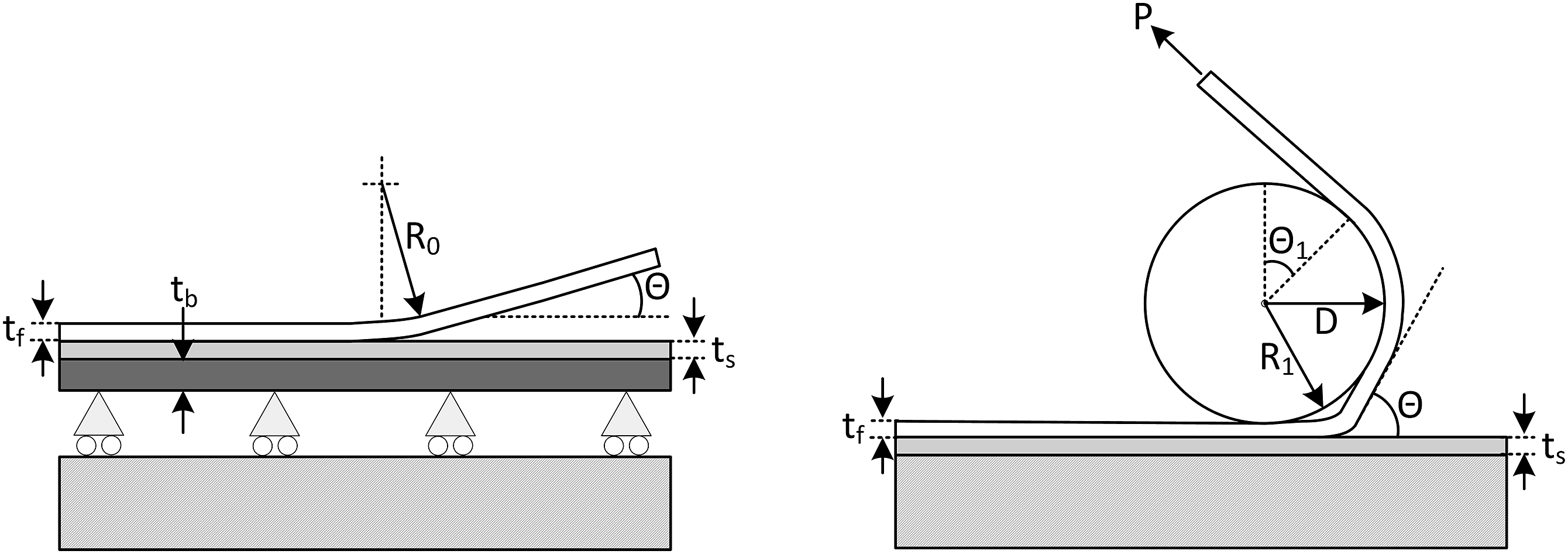
As discussed, the conformity of the bending arm during peel tests is a critical issue. Based on the 90° peel test, Sexsmith and Troczynski
106
added a mandrel in order to improve control of the peel angle. They later modified the novel mandrel peel test with an alignment force, pulling the peeled-off strip at the end of the specimen, see Figure 9. This enables a direct control of the conformity of the adherent to the mandrel,
107
which distinctly separates it from the floating roller and the climbing drum test. Mandrel peel test set-up according to Sexsmith and Troczynski.
107
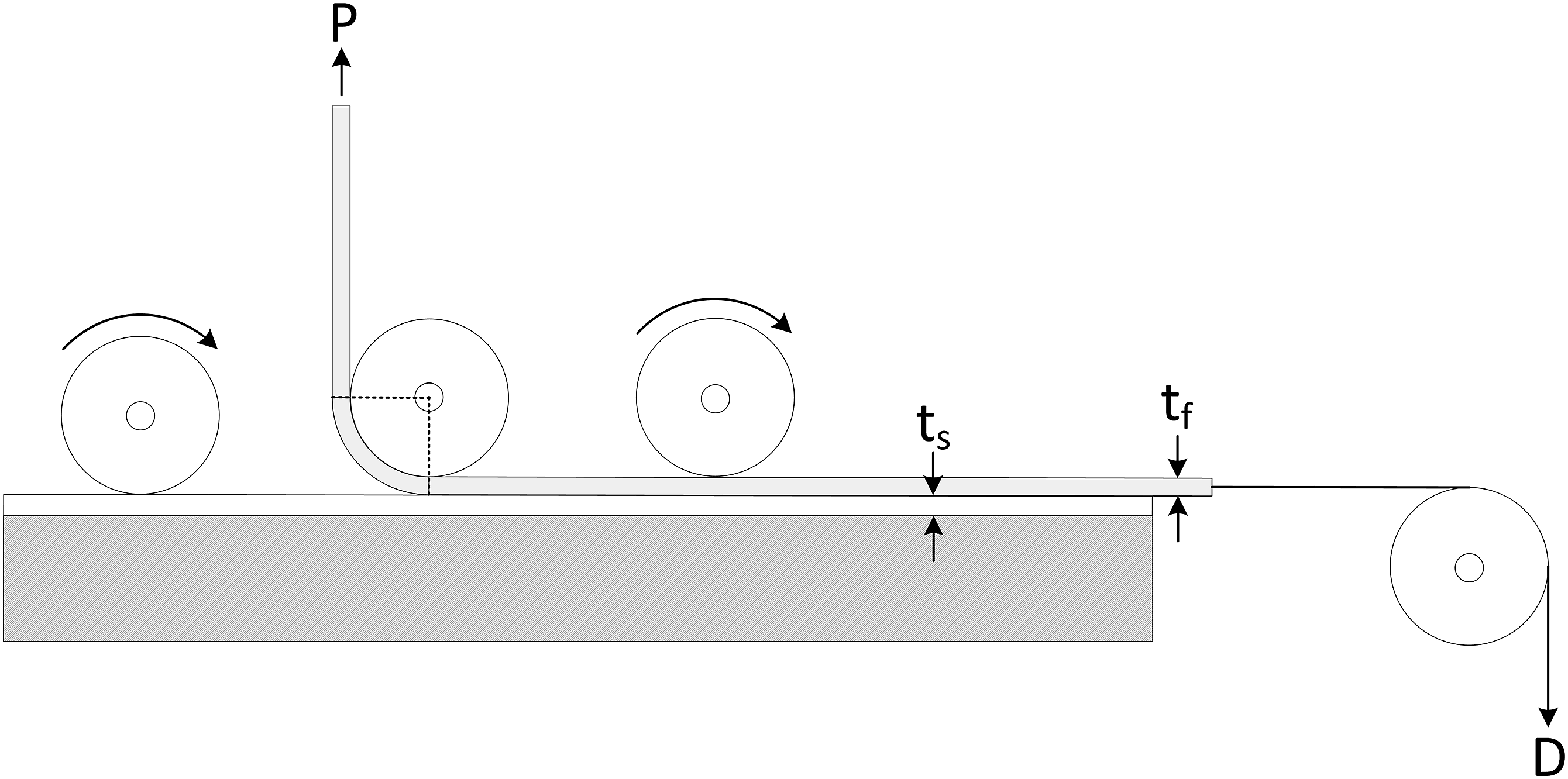
Another significant advantage is the direct experimental assessment of the dissipative energy component

Translating the energy into a force balance analysis and neglecting the elastic energy stored in the flexible adherent, Breslauer and Troczynski
102
calculate the relationship between the interfacial fracture toughness

Based on equation (9), the true fracture toughness
Following this work, other researchers used this mandrel peel method for the evaluation of interfacial fracture toughness of different material combinations. Kawashita and co-workers103,123,133,136 adapted the set-up of this method using a moving base carrier and applied it on the determination of interfacial fracture toughness of structural metal-polymer hybrid laminates.
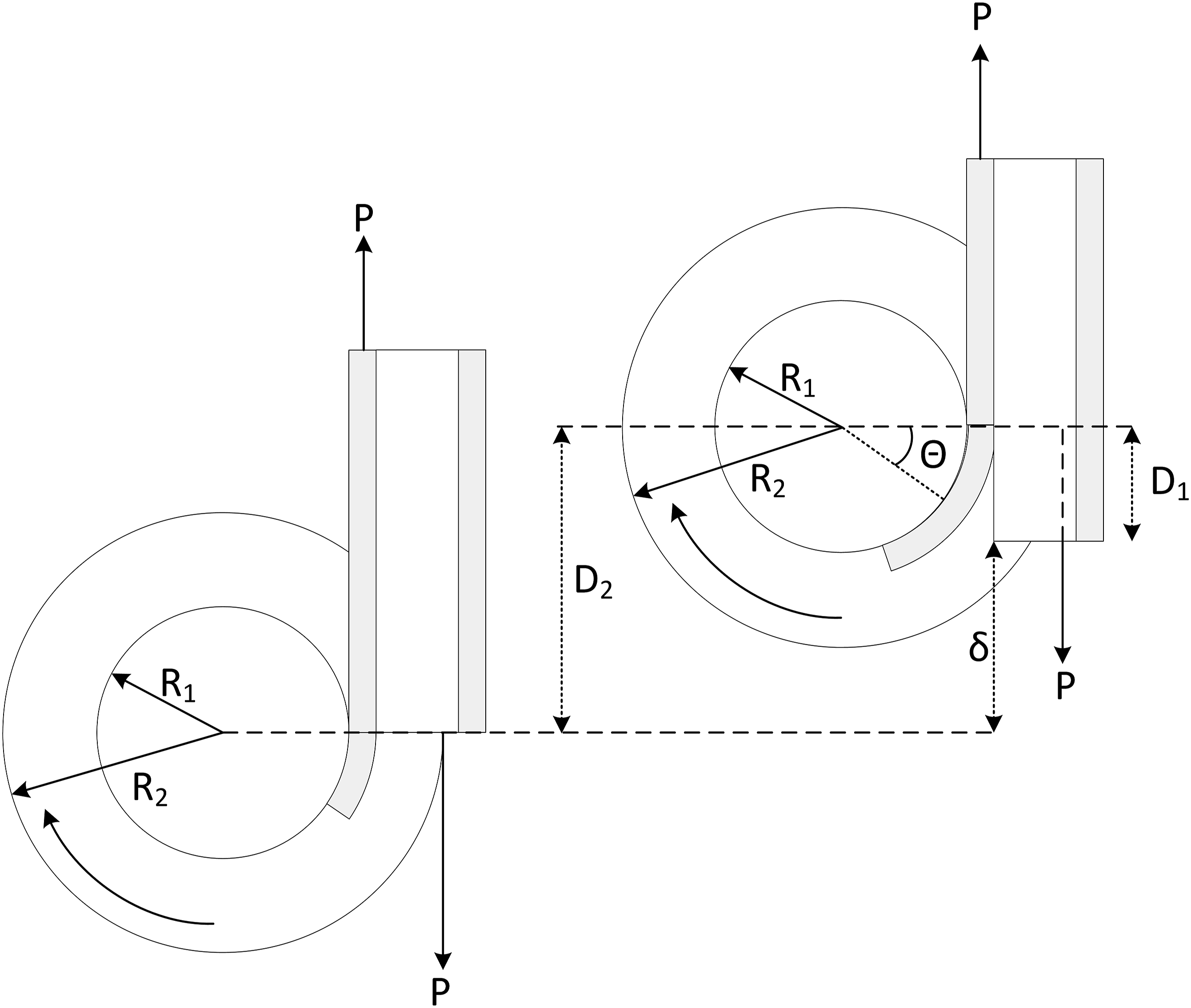
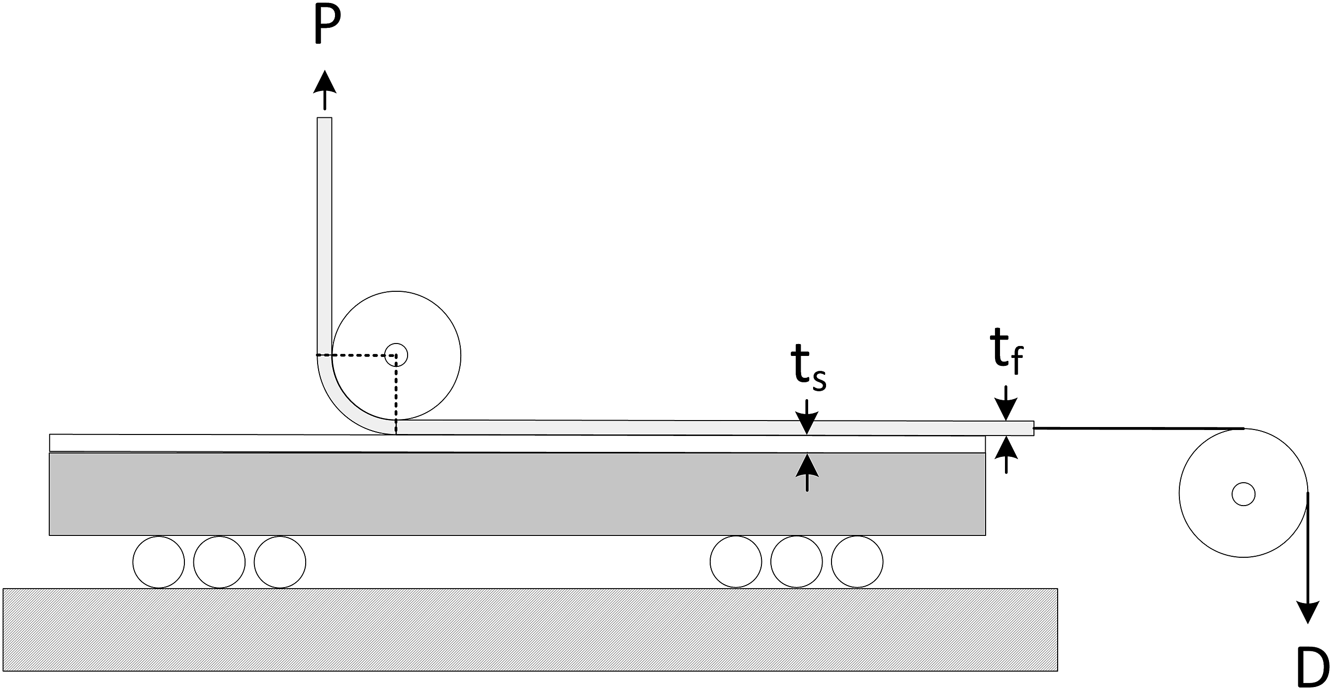
A comparison of different peel tests suggests that the adapted mandrel peel test is very well suited for the valid experimental assessment of interfacial fracture toughness of metal-polymer hybrid structures and benefits from its ‘elegant simplicity’.123,136 Following the work of Kawashita and co-workers, Grouve and co-workers122,137 evaluated the use of the mandrel peel test for thermoplastic composite-composite interfaces manufactured using automated thermoplastic tape placement, see Figure 10. Thermoplastic tape placement of unidirectional fibre reinforced thermoplastic tapes (UD-tapes) involves thin UD-tapes being continuously placed and welded in one process step according to the desired layup. Grouve et al.
122
calculated the SERR during debonding of these interfaces using an energy balance taking into account residual stresses in the bending arm, which may be induced due to the tape placement process and the involved thermal history. It was found that for the UD-tapes used the plastic work during bending and also residual stresses can be neglected.122,137 This leads to the calculation the interfacial fracture toughness Mandrel peel test set-up according to Grouve et al.
122

This approach to determine the true SERR during debonding is equivalent to the Breslauer and Troczynski
102
approach (equation (9)), considering the neglect of plastic work
In addition to the testing of the interfacial bonding of UD carbon laminate with polyphenylene sulphide (PPS) matrix and UD tape reinforced carbon-PPS woven laminate, 122 the mandrel peel test was used for the assessment of the SERR of the debonding interface of various other combinations of thermoplastic composite interfaces94,95 as well as thermoplastic composite metal interfaces.97,98 In addition, interfacial bonding of full thermoplastic composite sandwich structures was evaluated using the mandrel peel test set-up. 18 Based on the results of these studies, the test procedure provides a high reproducibility94,136 and mostly avoids kinking of the crack into one of the thermoplastic composite adherents.18,122 Kok et al. 95 however find that with high interfacial toughness between carbon fibre reinforced PEEK tape adherents, the crack may propagate into in the flexible adherent as the fibre matrix adhesion may exhibit lower crack resistances than the interface. In addition, they find that this is depending on the fibre orientation. In accordance with the findings of Kawashita and co-workers,123,133 they indicate the necessity not only to focus on fracture toughness test results but also on the failure mode.
Regarding the Mode I dominance of the mandrel peel test, limited research is available, yet it indicates Mode I dominant crack propagation. Sacchetti et al. 94 find Mode I dominant crack propagation during debonding of woven carbon fibre reinforced PEEK composites, based on a comparison of SERR using DCB and the mandrel peel test. Both test methods yield similar results, although the mandrel peel test leads to a little lower SERR values. Also, Grouve et al. 122 found that the SERR during debonding of UD-UD as well as UD-woven carbon fibre reinforced PPS interfaces was about 20 % lower than using the DCB method, which is partly attributed to decreased fibre bridging using the mandrel peel test compared to DCB. Another reason may be due to a more Mode I dominant behaviour at the crack tip using the mandrel peel method, which was shown to lead to lower SERR compared to Mixed Mode behaviour in case of DCB and SCB test methods. 77 In addition, SEM analysis of the fracture surfaces of DCB specimens and mandrel peel specimens showed similar fracture characteristics exhibiting signs of Mode I crack behaviour.94,122
Direct comparison of mode I dominant interfacial fracture toughness test methods
Evaluation of Mode I dominant test methods for the assessment of skin-core bonding of thermoplastic sandwich structures: ++ ‘very good’, + ‘good’, o ‘neutral’, - ‘fair’ and -- ‘poor’.
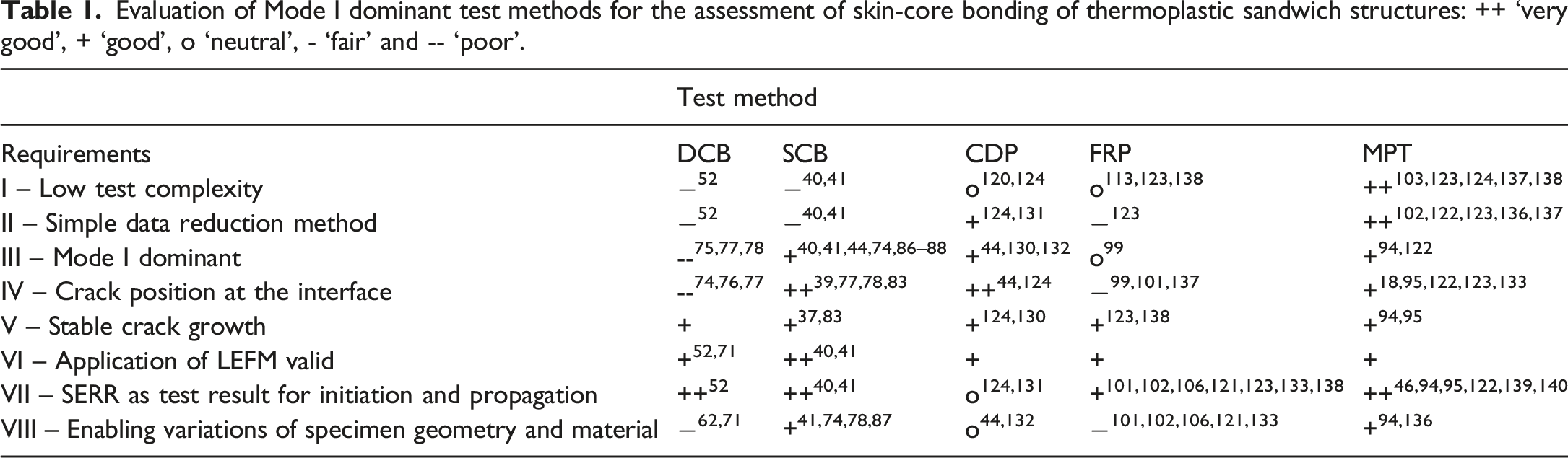
However, it is generally recommended that the determined
Conclusion
The present work shall contribute to select and further on to establish a suitable test method for the assessment of Mode I interfacial fracture toughness of thermoplastic sandwich structures. For this reason, promising test procedures are reviewed and evaluated in this paper. The considered test methods are the DCB, the SCB and different variants of peel tests. To evaluate the applicability of these test methods, eight requirements for suitable skin-core bonding test methods for thermoplastic sandwich structures are defined.
In this review it is found that the DCB test method used for sandwich structures exhibits a certain Mode II fraction, which is mainly attributed to the asymmetric load introduction in addition to the bi-material effect of sandwich structures resulting from different properties of skin and core. In addition, the DCB method shows tendencies of crack kinking. This characteristic for the DCB method used for sandwich structures is attributed to a positive shear stress at the crack tip. Consequently, the DCB method does not comply with the requirements for suitable test methods for skin-core bonding of sandwich structures.
In order to avoid the crack kinking phenomenon, several researchers propose the SCB as test method for interfacial fracture toughness assessment of sandwich structures. The SCB method exhibits only a minimal tendency of crack kinking into the core and distinctly less compared to the DCB method. Also, the major issue of specimen rotation is avoided as the specimen is fixed on a rigid substrate. According to literature, the SCB method leads to a clear Mode I dominant failure at the skin-core interface of sandwich structures. Also, the Mode I dominance is almost unaffected by crack length and facesheet thickness. However, the SCB test method does not allow valid testing of composite sandwich structures with very thin and compliant facesheets, respectively, since excessive bending of the facesheets near the crack tip cannot be avoided leading to facesheet failure and invalid results.
For this reason, peel tests appear promising since some of them control the bending radius of the facesheets by design. Peel tests considered in this paper are the climbing drum, the floating roller and the mandrel peel test. Recently published data reduction methods enable the determination of interfacial fracture toughness using the CDP. Authors showed that the SERR are similar to those using the SCB method and that they are independent of the facesheets thickness. However, the SERR values may differ depending on the radius of the drum. The use the latter avoids excessive bending of composite facesheets, yet perfect conformity cannot be guaranteed a priori. This is also found for the floating roller test method, which is typically used for flexible-rigid material interfaces. Due to the insufficient conformity, testing results are prone to inaccuracies, as calculations of the dissipative energy fractions during testing involved by the adherent material behaviour are required. In order to avoid these complex calculations for the assessment of interfacial fracture toughness using peel tests, the mandrel peel test was proposed by different authors. According to their studies, the method enables the direct experimental assessment of the SERR of a debonding interface. Available literature suggests that the method is reproducible and Mode I dominant. Also, it avoids crack kinking into the core. Considering the defined requirements for suitable Mode I dominant test methods for thermoplastic sandwich structures, the mandrel peel test yields most promising overall characteristics of all methods considered in this work.
In future studies, experimental campaigns analysing the skin-core bonding of full thermoplastic sandwich structures should be conducted using the SCB and the mandrel peel test in order to provide a direct comparison of the SERR results as well as of the specific skin-core fracture surfaces. Also, the applicability of these methods for thermoplastic sandwich structures with different core structures and facesheets should be assessed.
Footnotes
Declaration of conflicting interests
The author(s) declared no potential conflicts of interest with respect to the research, authorship, and/or publication of this article.
Funding
The author(s) disclosed receipt of the following financial support for the research, authorship, and/or publication of this article: This work was supported by the European Union’s Horizon 2020 research and innovation programme (grant number 770019).