
Abstract
Interleaving of thermoplastic veils within carbon fibre composites is a method commonly utilised to increase the fracture toughness of composite materials. Previous studies have presented a range of fracture toughness values attributed to the inclusion of polyamide based thermoplastic veils; however, a large portion of these have remained focused on the use of veils that retain their fibre structure during the laminate cure cycle. This study sets out to explore the Mode-I fracture toughness and resultant failure mechanisms of a carbon/epoxy composite interleaved with a low-melt copolyamide thermoplastic veil at different areal densities. The results reveal that the thermoplastic veil polymer successfully precipitated from the initial veil fibre structure during the cure cycle resulting in a phase transformation from veil fibres to bead-like particles across the interlayer. As the veil density is increased, there is a decrease in the Mode-I fracture toughness with a reduction of 23%, 33% and 52% for 8, 14 and 20 g/m2 veil configurations. Fractography of the fracture surface revealed the weak interface between the phase separated Co-PA particle and epoxy matrix as the primary failure mechanism across all interleaved laminates. Microscopic analysis demonstrated that the use of low-melt copolyamide veils resulted in a semi-uniform distribution of precipitated thermoplastic particles in low veil densities (8 g/m2), however led to a slightly larger particle size and onset of agglomerations as the density was increased (14 g/m2) before forming a bi-continuous phase at high veil densities (20 g/m2) leading to larger reductions in the calculated fracture toughness.
Introduction
The introduction of carbon fibre reinforced epoxy (CF/EP) composites has positioned this class of materials as a favourable alternative to traditional metallic structures used in aerospace applications, owing to their enhanced modulus of elasticity, resistance to deformation and increased stiffness/durability. 1 A key characteristic of CF/EP composites, namely their high stiffness-to-weight ratio, allows aircraft manufacturers to develop an aerostructure that responds exceptionally well to dynamic flight loads while concurrently reducing the extent of operational costs and carbon emissions of the aircraft resultant of a fuel efficiency increase due to its lightweight properties. 2 A notable vulnerability of CF/EP composites surrounds their brittleness and damage tolerance to impact events which may occur inflight or while grounded, with common sources of damage arising from bird strikes, hailstorms and accidental tool drops during service and maintenance intervals. These impact events, while pertinent to their severity, typically lead to delamination’s within the subsequent plies forming a damage rosette which evolves both in-plane and through the thickness of the laminate. 3 The fracture may be confined to the interlaminar bounds, however, may also branch to surrounding plies and propagate to other intralaminar regions leading to catastrophic failure of the substrate.4,5 Understanding damage evolution within CF/EP composite structures, the notion of matrix modification to delay the onset of damage and impede the subsequent crack propagation has become an increasingly prominent field of study amongst researchers.4,6–9
The ability for a laminated material to resist crack initiation and propagation at its laminate interfaces, is often referred to as the interlaminar fracture toughness (IFT) of the system. A characteristic parameter closely related to a materials IFT is referred to as the critical strain energy release rate, GIC, and represents the energy required to propagate a crack between the layers of the laminate per unit area of the crack surface. To quantify the composites’ resistance to delamination, the Mode-I fracture toughness is frequently reported in literature as a means of comparison. 10
Matrix modification is an approach that is used to toughen resin systems and is done so with the intent of increasing the material’s fracture toughness. Although the direct addition of nanoparticle toughening agents within resin systems has proven to be an effective means of toughening, issues surrounding the uniformity of particle distribution due to fibre filtering as well as an overall increase in the resin viscosity have been documented to occur especially under the liquid composites moulding process. 11 One alternative technique that has shown significant enhancements to the fracture toughness of CF/EP composites is the interleaving of thermoplastic non-woven veils between plies of carbon fibre. Various types of thermoplastic non-woven veils have been successfully used as interleaves with a large proportion demonstrating increases in the Mode-I fracture toughness of the laminate.12–15 Materials such as Polyamide (PA),13,14,16,17 Polyethylene Terephthalate (PET) 18 and Polyphenylene Sulfide (PPS)19,20 have shown to be compatible with epoxy resin systems and have demonstrated their suitability as interleaves within CF/EP composites. Depending on the type of thermoplastic used, melting temperatures can be selected so that they are either above or below the resin cure temperature. 21 In cases where the cure temperature is less than the thermoplastic melting temperature, the veil retains its fibrous structure across the interlayer. On the contrary, when the thermoplastic veil melting temperature is less than the epoxy cure temperature, the thermoplastic melts, loses its fibrous structure and integrates within the epoxy matrix often via means such as phase separation.22–24 Thermoplastic non-woven veils have also demonstrated their capacity to act as efficient nanoparticle carriers, distributing nanoparticles such as silver nanowires (AgNWs) 25 and graphene 26 across the interlaminar surface of adjacent plies, often leading to further increases in the fracture toughness of the composite.
PA veils have gained popularity as interleaves in CF/EP composites due to their intrinsic properties. They are lightweight, easy to manufacture/process and cost-effective, making them an attractive solution in aerospace applications. Several studies have been conducted on the fracture properties of composites interleaved with PA non-woven veils of different classes.16,27–30 Across each of the studies, fractographic analysis highlighted the importance of interface adhesion between the thermoplastic fibre and epoxy resin. Indications of bridging of the thermoplastic fibres lead to an overall increase in the laminate fracture toughness, attributed to the increase in ductility resulting from the presence of PA fibres.12,17 Conversely, Daelemans et al. 16 reported reductions in the Mode-I fracture toughness of composites interleaved with PA-66 non-woven veils, indicating a weak fibre-resin interface in conjunction with a suppression of carbon fibre bridging due to the veil presence led to a fracture toughness that is lower than of the virgin laminate.
A recent study by Narongdej et al. 21 investigated the effect of non-woven melting temperature on the matrix toughness of carbon fibre/benzoxazine composites. They observed a larger increase in the initiation and propagation fracture toughness in specimens interleaved with veils that fully melted during cure attributing the increase in fracture toughness to a combination of good particle-matrix adhesion and plastic ductility. Interestingly, they reported increased scatter in the melted veil dataset, indicating melted thermoplastic veils can result in inhomogeneous distributions across the interlaminar zone, leading to defect-like agglomerations. Similarly, Alshrif et al. 15 explored the effects of low-melt Co-Polyamide (Co-PA) veils on the interlaminar toughness of carbon fibre/epoxy composites. They reported a maximum increase of 148% in the Mode-I fracture toughness of the laminate, owing to the increased ductility resulting from the presence of the phase separated Co-PA particles that resulted from the precipitation of the initial veil fibre structure. An important observation was made regarding the Mode-I fracture toughness as a function of areal weight. The authors found that as the veil weight was increased to 16 and 20 g/m2, the formation of a bi-continuous Co-PA/epoxy phase developed across the interlayer leading to enhanced Co-PA particle-bridging across the crack surface. In the case of meltable PA veils, the degree of precipitated particle-matrix adhesion is critical in the consequent fracture toughness of the interleaved laminate and influences the fracture mechanics, leading to cohesive particle failure or, in cases of weak interfaces, particle-matrix debonding. 31
There is a lack of published literature directly pertaining to the analysis of failure mechanisms in CF/EP composites when interleaved with low-melt Co-PA veils. The aforementioned studies indicate that when particle-matrix adhesion is adequate, there is an increase in the ductility of the interlaminar region attributed to the properties of the phase separated polymer. However, studies on the implications on the fracture toughness and critical failure mechanisms of a laminate consisting of precipitated Co-PA particles that present a weak particle-matrix interface is limited across literature and requires further analysis to develop a deeper understanding into these critical mechanisms. A low-melt Co-PA veil was interleaved at different areal densities with the aim of understanding its effects on the fracture toughness of a laminate under Mode-I loading conditions. Further to this, analysis on the failure mechanisms is conducted to better understand how meltable Co-PA veils influence the failure modes of the laminate.
Materials and experimental methods
Materials
Laminates were manufactured using SGL SIGRAPREG E320 unidirectional carbon fibre prepreg of 230 g/m2 fibre and 39% resin content. The E320 system is an epoxy matrix that is processable at a wide range of curing pressures and temperatures based on the selected manufacturing method. The Co-PA non-woven veils were commercially purchased. The areal weights of the thermoplastic veil were 8, 14 and 20 g/m2 respectively. The veils were manufactured from a polymeric blend of PA6/PA66 thermoplastic with a melt temperature of 107°C.
Manufacture of composite laminates
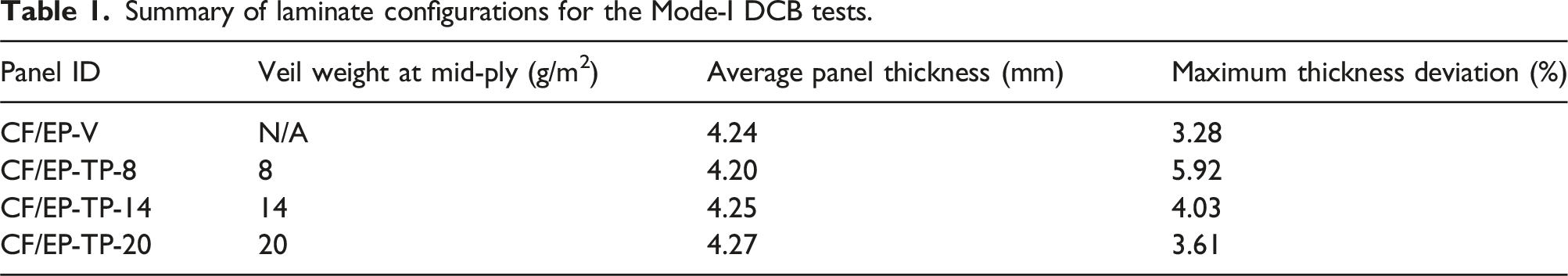
For the Mode-I fracture toughness studies, laminates were manufactured using a Vacuum Bag Only (VBO) layup as represented in Figure 1. Laminates consisted of 18 plies of unidirectional prepreg stacked in the 0o fibre direction. A total of four laminates, 300 mm × 300 mm in size were manufactured and summarised in Table 1, each of which containing a Polytetrafluoroethylene (PTFE) film insert of 10 µm in thickness meticulously positioned at one end of the mid-plane to create an artificial delamination/crack initiator. For each interleaved laminate, the relative thermoplastic veil was cut to size, dried at 40°C under vacuum for 24 h prior to the cure as per the manufacturer recommendations and inserted between the mid-plane (9th and 10th ply) across the entire surface. The non-wovens used in this study presented some degree of fibre alignment in the direction parallel to the spool length and as such, for each interleaved laminate, the veil was orientated such that the Co-PA fibres were aligned perpendicular to the direction of crack growth. An edge breather in the form of dry glass tows was used around the perimeter of the laminate to assist in the evacuation of entrapped air formed during the layup process. Schematic of the vacuum bag layup used to cure laminates for Mode-I fracture toughness tests. Summary of laminate configurations for the Mode-I DCB tests.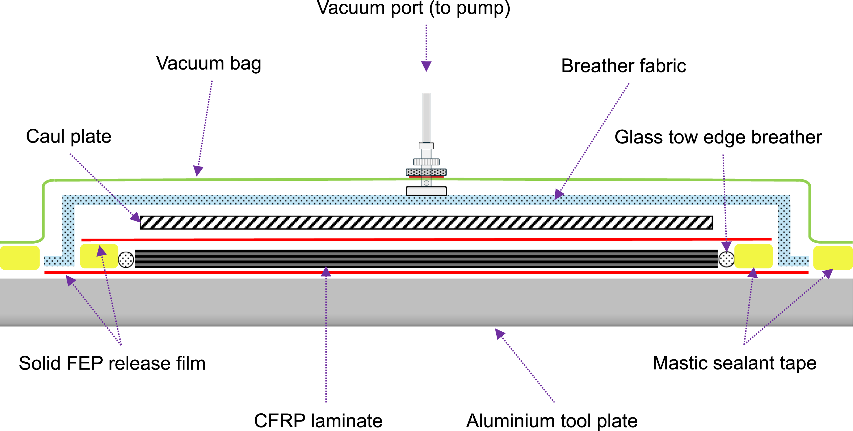
The laminates were laid up and debulked under vacuum overnight before being processed using a composite curing oven under constant vacuum pressure (shown in Figure 2). The cure cycle followed was optimised based on the prepreg manufacturer’s exemplary recommendation as well as an initial thermal survey of the oven’s internal heat distribution to minimise temperature gradients across the part surface. The laminates were ramped from ambient temperature of 23°C to 80°C at a rate of 2°C/min, dwelled for 50 min before being ramped to 125°C at a rate of 2°C/min and held for another 70 min. Upon completion of cure, the laminates were cooled to room temperature at a rate of 2°C/min before they were removed from the oven. Temperature data was captured using a PicoLog TC-08 temperature data logger at four locations across the laminate for the duration of the cure to verify the local part temperature with respect to the cure time. Oven cure processing of vacuum bagged laminate for the production of Mode-I test specimens.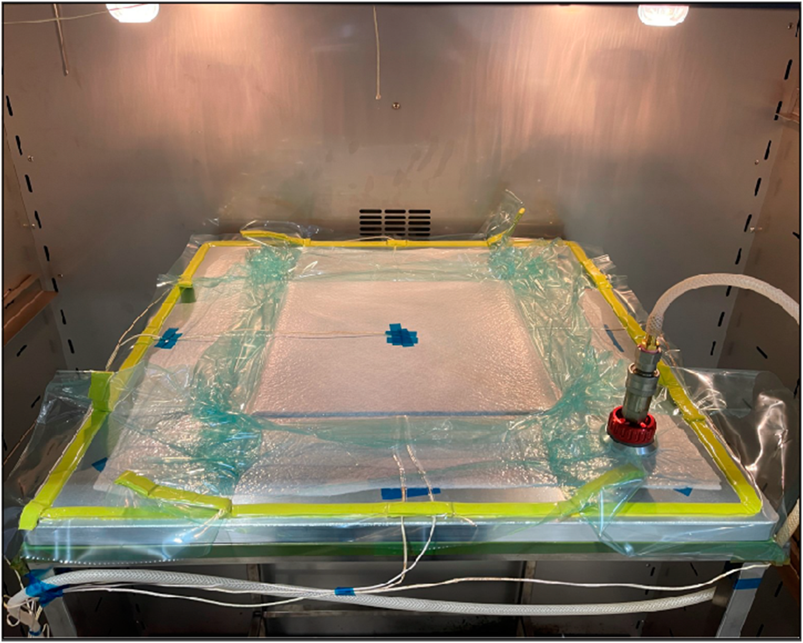
Characterisation
Mode-I interlaminar fracture toughness
Mode-I interlaminar fracture toughness tests were carried out via the Double Cantilever Beam (DCB) tests in accordance with ASTM D5528-21. 10 For each test, specimens were extracted from the laminate using a water jet cutter. Specimens for Mode-I fracture toughness testing were 200 mm long and 20 mm wide with an initial crack length (a0) of 50 mm. To introduce the load, each specimen was bonded with steel piano hinges on both sides at the PTFE insert end. A 3M 07447 Scotch-Brite pad was used to scuff the surface of the carbon fibre, while the underside of each piano hinge was thoroughly grit blasted and acetone washed to promote stronger bond line adhesion. Both the carbon and hinge surface were coated in a thin layer of Teroson EP 5065 two-part epoxy adhesive supplied by Henkel. A bonding jig was designed and manufactured to assist with the location and alignment of the piano hinge in relation to the specimen and fibre direction, respectively. Each side of the specimen was painted using white water-based correction fluid before a wound measurement sticker was applied on the side of the specimen to assist in the measurement of the crack propagation at 1 mm intervals from the end of the PTFE insert.
Figure 3 illustrates the experimental setup and used throughout the Mode-I fracture toughness tests. The test was carried out using a Zwick Roell Z010 test machine with a 1 kN load cell. An LED illuminated digital microscope camera (Celestron®) was mounted in front of the fixtures to isolate and capture the crack propagation across the mid-plane. Specimens were loaded at a crosshead displacement rate of 1.0 mm/min and unloaded at 5.0 mm/min as per the ASTM D5528-21 recommendations. Data was captured continuously for a total crack propagation length of 50 mm. A total of six specimens were tested for each laminate configuration. (a) Mode-I fracture toughness test arrangement depicting digital microscope camera setup, (b) specimen orientation within fixtures.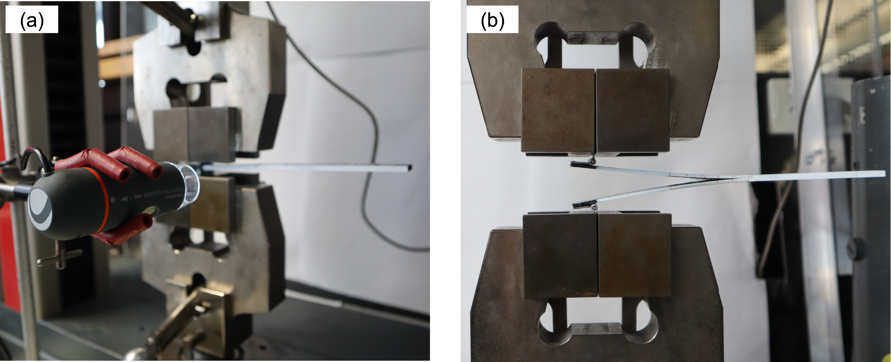
The Mode-I strain energy release rate, was calculated using the Modified Beam Theory (MBT) data reduction method, represented as equation (1), whereby P is the applied load, δ is the relative load-point displacement, b is the specimen width, a is the delamination length and Δ is introduced as a crack length correction factor, experimentally determined by generating a least-square-plot of the cube root of compliance, C1/3, as a function of delamination length. Due to the stick-slip nature of the material, the maximum load point was used for the calculation of the initiation energy (GICini).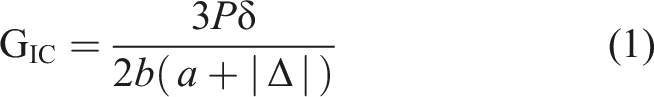
Optical microscopy
An Olympus DSX1000 optical microscope was employed to characterise the interlaminar region of the laminates. Optical microscopy was also employed to characterise the fracture surface and crack propagation pathway for virgin and interleaved specimens once Mode-I fracture toughness testing was completed.
Scanning electron microscopy
To analyse the fracture surface and failure mechanisms of the specimens, a Zeiss Supra 40 VP Scanning Electron Microscope (SEM) was utilised. The specimen arms were fully separated at the conclusion of testing before being sectioned into 10 mm wide sections. A Quorum Q 150R ES Plus sputter coater was used to coat the samples which were extracted 30 mm from the PTFE end point. Specimens were coated with gold for 20 seconds at a current of 40 mA.
Results and discussion
Characterisation of Co-PA veils
The morphology of each Co-PA veil configuration was investigated and characterised using optical microscopy and are presented in Figure 4. Analysis on the fibre diameter was conducted and found to remain constant across all areal weights with an average fibre diameter of 8.61 ± 1.09 μm. As the veil density increased, there was a visible decrease in the porosity across the area due to an elevated presence of Co-PA fibres crossing amongst each other. An important observation was made regarding the overall alignment of Co-PA fibres across each veil configuration. It was found that the Co-PA fibres demonstrated a tendency to align in a direction parallel to the length of the non-woven spool. However, as the Co-PA veil used in this study was low melt in nature, the fibre structure was lost during the cure cycle via precipitation and therefore, any influence of such fibre alignment was mitigated throughout the study. Visualisation of veil morphology and microstructure for (a) 8 g/m2, (b) 14 g/m2, (c) 20 g/m2 areal densities.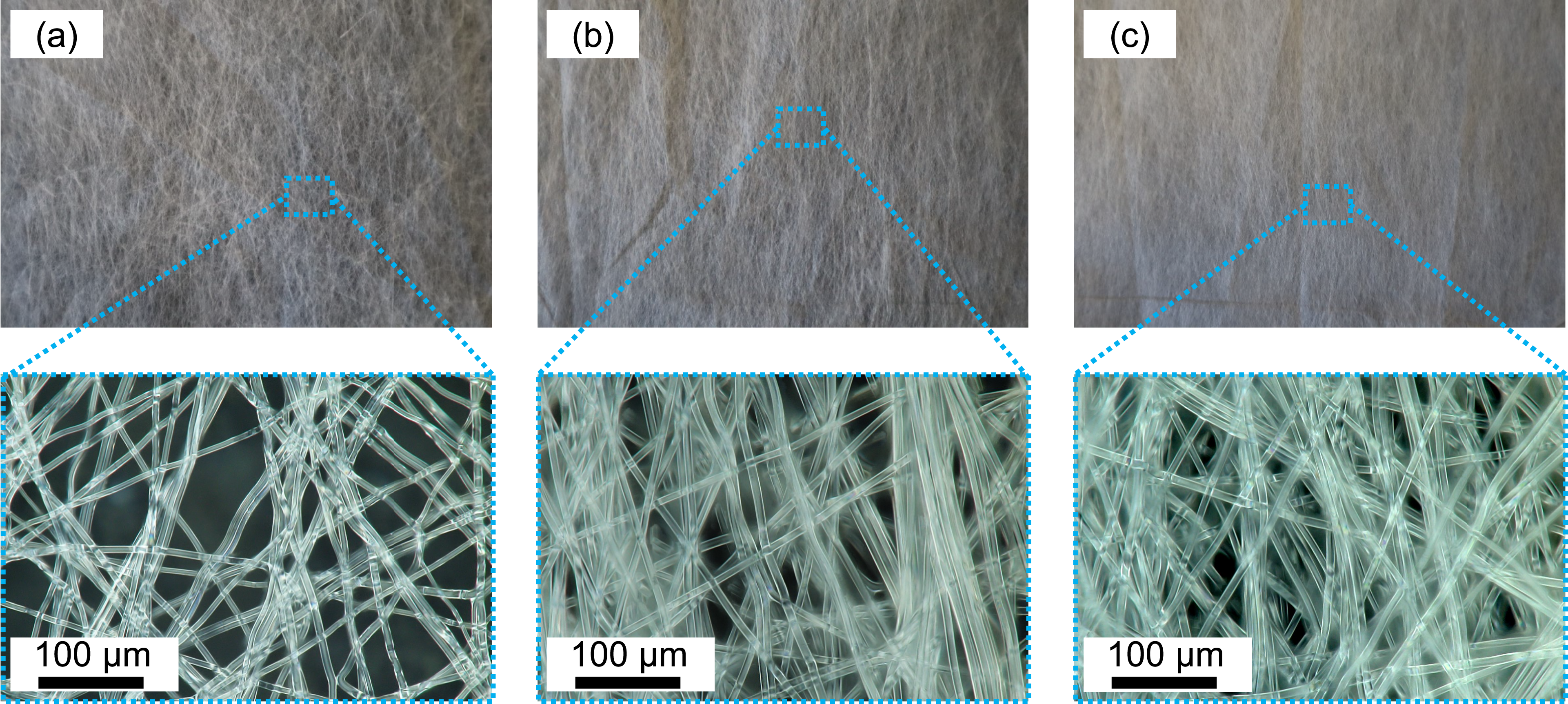
Micrograph cross-sections of the virgin and interleaved laminates are represented in Figure 5 and highlight the mid-ply interlayer. It was observed that there was negligible difference in the interlayer thickness resulting from the presence of the thermoplastic non-woven veils. In Figure 5(b) to (d), there was evidence of thermoplastic particles dispersed across the interlayer (encompassed in dotted white circles). As the areal density of Co-PA non-woven increased, there was a slight increase in the visible size of thermoplastic particle that formed through the interlayer as well as the tendency for particle agglomerations to form. Optical micrographs representing the mid-ply interlayer region across (a) Virgin, (b) 8 g/m2, (c) 14 g/m2, (d) 20 g/m2 laminate configurations.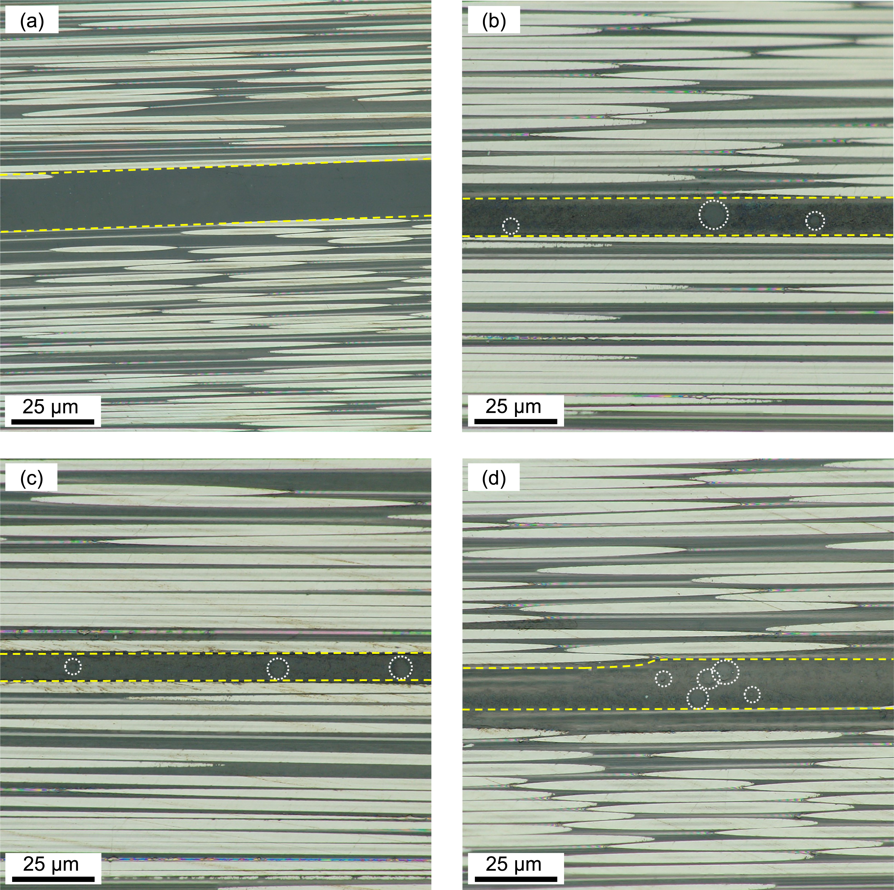
Effect of Co-PA veil areal density
Mode-I interlaminar fracture toughness
Figure 6 illustrates the representative load-displacement curves captured for the Mode-I fracture toughness tests. The load-displacement curves of the DCB specimens exhibit a relatively linear increase up until the point of crack initiation with exception to the first 15 N of load resultant of the compliance within the test fixture. As the material in all cases exhibited significant stick-slip due to the presence of unstable crack propagation, pre-cracking from the PTFE insert was not conducted. A round robin test was initially performed on each laminate configuration to understand the material behaviour which identified the tendency for crack initiation growth to exceed the ASTM recommendations of 3–5 mm, with cracks in some specimens propagating upwards of 15 mm from the PTFE termination. Representative Mode-I force-displacement curves for virgin, 8 g/m2, 14 g/m2 and 20 g/m2 laminate configurations.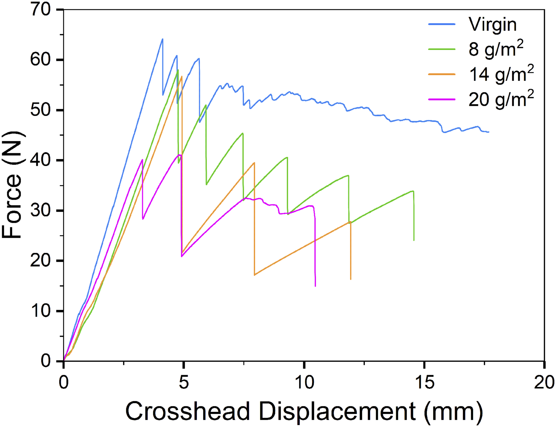
From Figure 6, a reduction in the magnitude of load required to initiate the crack from the PTFE insert was observed as the areal density of the non-woven veil across the interlayer increased. Virgin specimens demonstrated the highest magnitude of load required to initiate the crack through the interlayer presenting a peak load of 64.2 N which was followed by an overall reduction in the crack initiation load of approximately 10%, 12% and 36% for the 8, 14 and 20 g/m2 configurations respectively. Virgin specimens initially exhibited unstable stick-slip behaviour with a rapid crack growth, indicative of a brittle resin system, before eventually transitioning to a stable propagation. It was found that, as the veil density was increased, a higher degree of stick-slip was observed and is evidenced by the saw-tooth like load-drops represented in the load-displacement curves (Figure 6). The larger magnitude of load-drop across the interleaved specimens corresponded to the unstable and highly rapid crack growth across the mid-plane which increased in severity as the non-woven areal density was increased.
Figure 7 presents captured images of the crack propagation during the DCB test obtained from the digital microscope camera. Virgin specimens (Figure 7(a)) exhibited a strong degree of fibre bridging which is well reported to be an intrinsic toughening mechanism in virgin carbon fibre laminates of a unidirectional orientation.32,33 For the case of interleaved laminates, the development of fibre bridging was significantly reduced in 8 g/m2 specimens (Figure 7(b)) and notably absent in the 14 g/m2 and 20 g/m2 specimens (Figure 7(c) and (d)). This primarily led to the development of highly rapid and unstable crack propagation across the plane, confirmed by a reduction in the number of crack arrest points observed in the load-displacement graphs. Static images of (a) Virgin, (b) 8 g/m2, (c) 14 g/m2, (d) 20 g/m2 laminate configurations during Mode-I testing.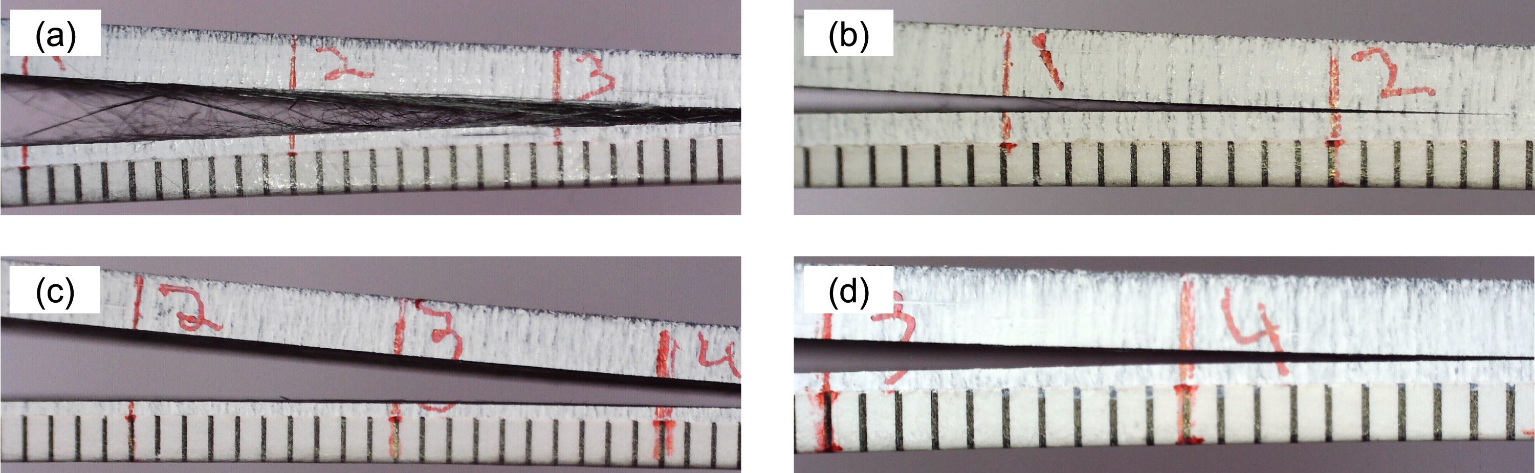
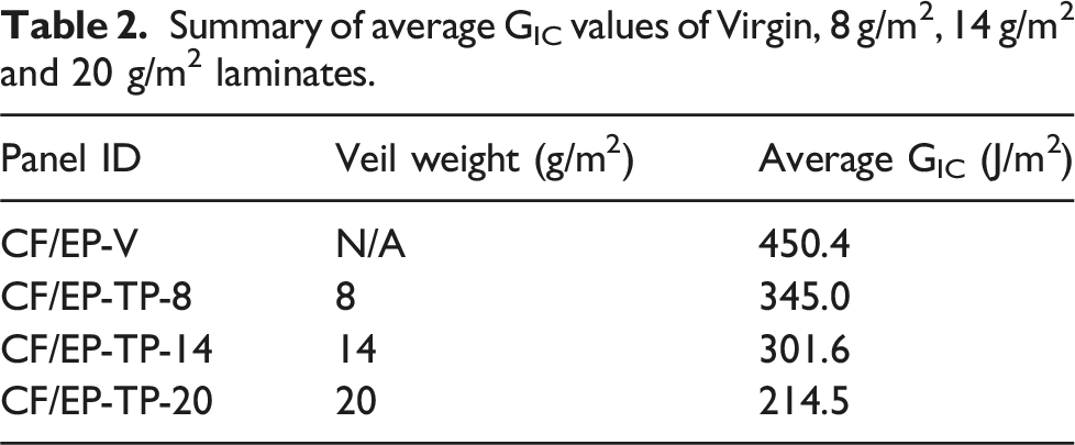
Summary of average GIC values of Virgin, 8 g/m2, 14 g/m2 and 20 g/m2 laminates.
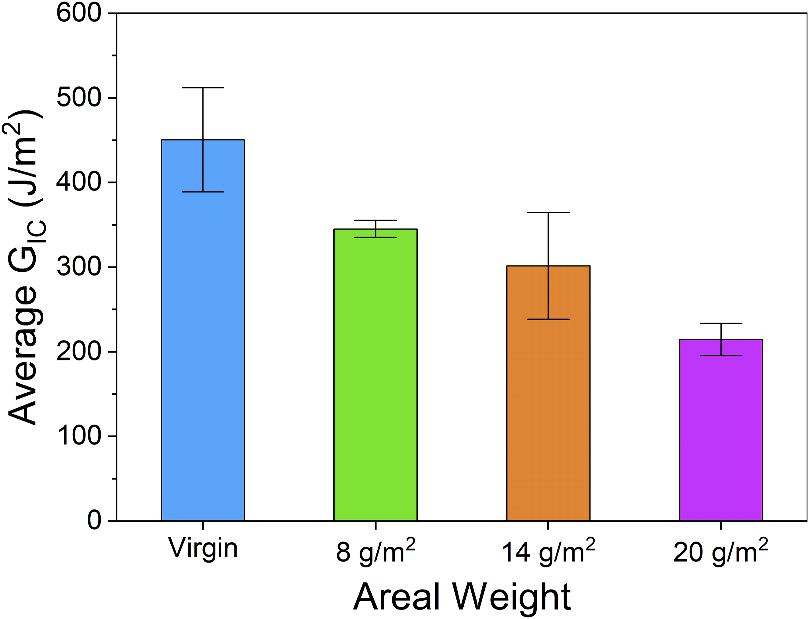
Visual representation of average GIC values as a function of veil weight (Error bars signify ± 1 SD).
In terms of the GICProp values, virgin specimens yielded the highest propagation toughness with an average of 450.4 J/m2. In specimens interleaved with the 8 g/m2 veil, the GIC value was reduced by 23% with an average GIC toughness of 345 J/m2. As the areal weight was increased to 14 g/m2, the average GIC value was reduced by 33% and calculated to be 301.6 J/m2. Finally, for the case of specimens interleaved with 20 g/m2 veils, the fracture toughness was reduced by 52% with an average of 214.5 J/m2.
The representative resistance curves (R-curves) for both virgin and Co-PA interleaved laminates are presented in Figure 9. A ‘rising’ trend in the R-curve of virgin specimens was observed which is reported to originate from the presence of fibre bridging within the specimen36,37 (as confirmed by the microscope camera observations in Figure 7). The representative R-curves for the interleaved laminates on the other hand show a significantly different trend when compared to the virgin laminate. In specimens interleaved with the 8 g/m2 veil, a relatively ‘flat’ R-curve was seen to exist with negligible change to the fracture toughness as the crack length increased. After reviewing the digital microscope camera footage, it was evident that the slight ‘rise’ in the representative curve was likely resultant of the formation of low-degree fibre bridging as seen in Figure 7(a). 14 g/m2 specimens produced a ‘falling’ R-curve and it is most probably a direct consequence of the melted thermoplastic particles inhibiting the formation of interlaminar carbon fibre bridging as the crack tip progresses across the mid-plane. Quan et al.
19
reported that thermoplastic interleaves may impede and suppress the formation of carbon fibre bridging across the interlaminar zone, leading to varying reductions in the GIC values of the interleaved laminates. For specimens interleaved with a 20 g/m2 non-woven at the mid-ply, a stable fracture toughness was observed as the crack length increased, evidenced by a relatively “flat” trend in the corresponding R-curve. One possible explanation for this phenomenon surrounds the differences in melt viscosity between the phase separated Co-PA particles and the epoxy resin.
8
During the cure cycle, melted particles may agglomerate and form localised clusters of dense Co-PA particles across the interlayer. In this situation, pockets of epoxy matrix that contain a reduced volume of thermoplastic may also exist across the interface, therefore assisting in the formation and development of localised fibre bridging zones. The works of Lan et al.
8
and Alshrif et al.
15
also conduced that, as the veil weight increased, there is a tendency for thermoplastic particle agglomerations to form throughout the resin matrix therefore supporting the notion of localised epoxy matrix zones leading to the development of fibre bridging to some extent. Representative Mode-I R-curves of both Virgin and Co-PA interleaved laminate configurations.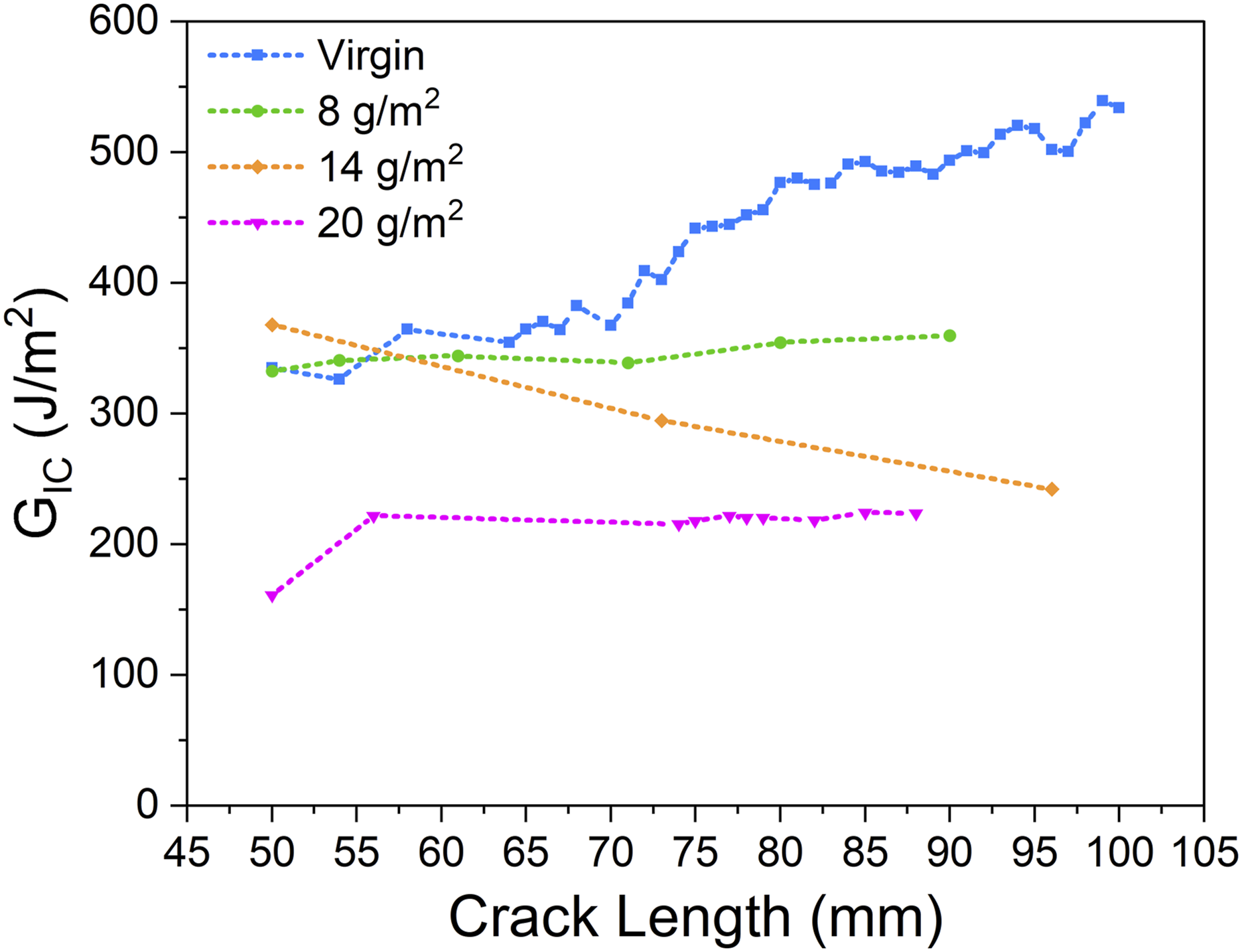
Fracture morphology/failure mechanism analysis
To truly understand the effects of low-melt Co-PA veils on the Mode-I fracture toughness, fractographic analysis was performed to identify the failure mechanisms across each laminate configuration. Figure 10 illustrates the crack propagation pathway for virgin, 8, 14 and 20 g/m2 laminate configurations. Figure 10(a) indicates that the crack propagation pathway for the virgin laminate is mostly adhesive failure along the fibre-resin interface as the primary failure mechanism indicating that the relative fracture toughness is highly dependent on the adhesive strength between the carbon and epoxy resin. There was evidence of fibre bundle separation and bridging fibres across the interlaminar region, therefore supporting the notion of fibre bridging as the primary toughening mechanism in the virgin specimens. This would also explain the source of the ‘rising’ R-curve that was observed in the case of virgin specimens. Contrastingly, all three interleaved laminates typically exhibited cohesive failure within the matrix as identified in Figure 10(b) to (d). The crack propagates through the matrix until it reaches the phase separated thermoplastic particle/agglomerate. The crack then proceeds to travel along the resin-particle interface as it progresses across the mid-plane. This phenomenon was observed in all interleaved specimens and can explain the reduction in GIC as the veil density increased. As the crack approaches the thermoplastic particle, there is poor adhesion between the particle and epoxy resin, leading to a weak interface which provides an energetically favourable pathway for the crack to propagate. Optical micrographs demonstrating the crack propagation pathway across the interlayer for (a) Virgin, (b) 8 g/m2, (c) 14 g/m2, (d) 20 g/m2 laminate configurations under Mode-I loading.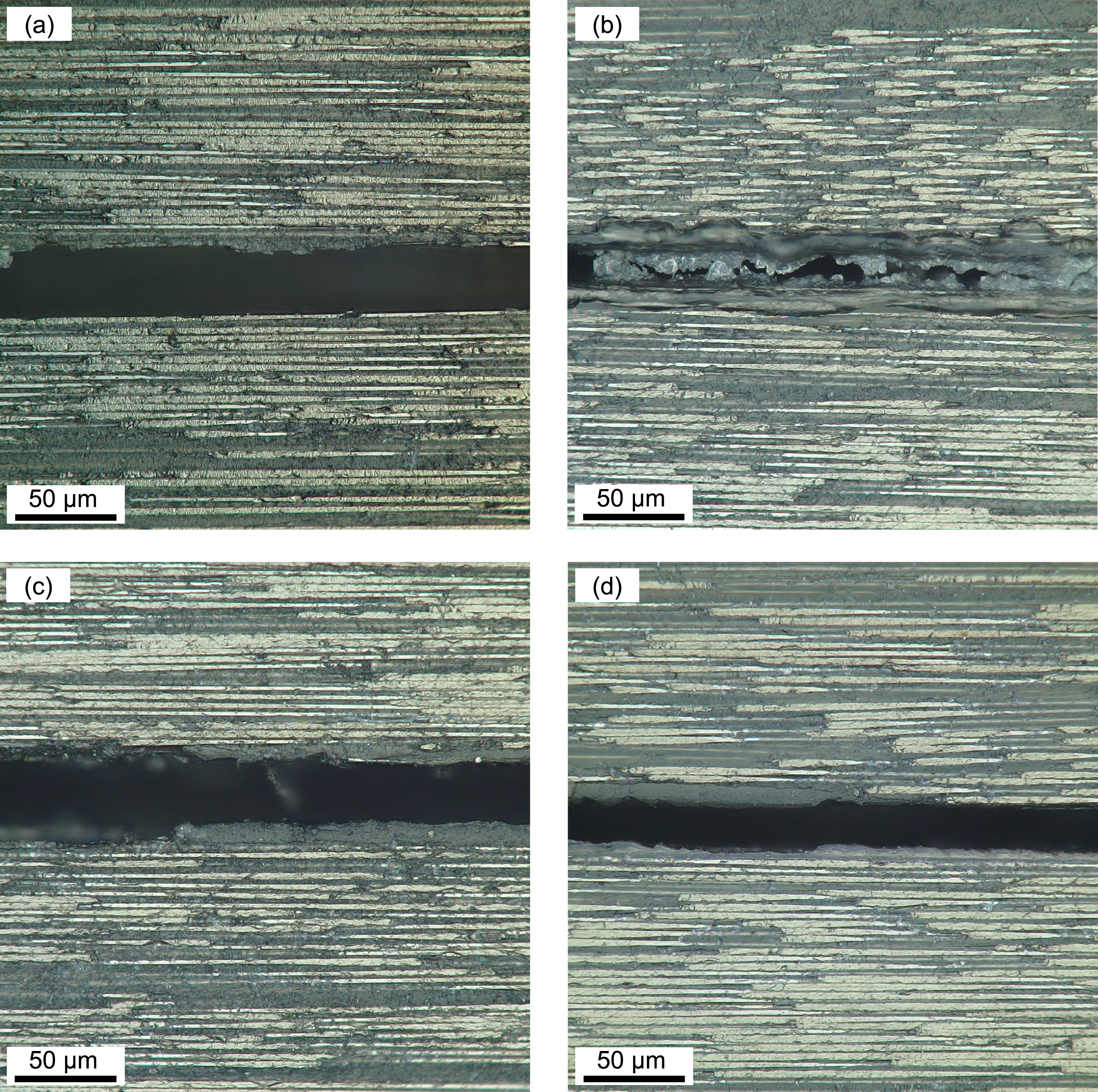
Figure 11 presents SEM micrographs of the fracture surface morphology for each laminate configuration. In the virgin specimens, the fracture surface is seen to be scattered with loose fibres across the surface. Additionally, there is strong evidence of fibre pull-out in the direction of crack growth with remnant pockets visible across the resin where fibres were once adhered to the matrix (Figure 11(a)). Similar failure mechanisms were observed by Ou et al.
38
who also reported fibre pull-out and breakage as the predominant failure mechanism in unidirectional CF/EP laminates. As presented in Figure 11(b) to (d), the fracture surface of all interleaved specimens displayed a relatively smooth resin-rich layer across the underlying fibres supporting the existence of cohesive failure through the interlayer.
16
Thermoplastic particles (represented by dotted green circles) were found to be dispersed across the epoxy matrix indicating successful phase separation of the melted Co-PA non-woven during the cure cycle. As the areal weight was increased from 8 g/m2 to 14 g/m2, there was an increase in the density and size of particles present across the fracture surface. SEM of fracture surface post Mode-I loading for (a) Virgin, (b) 8 g/m2, (c) 14 g/m2, (d) 20 g/m2 laminate configurations.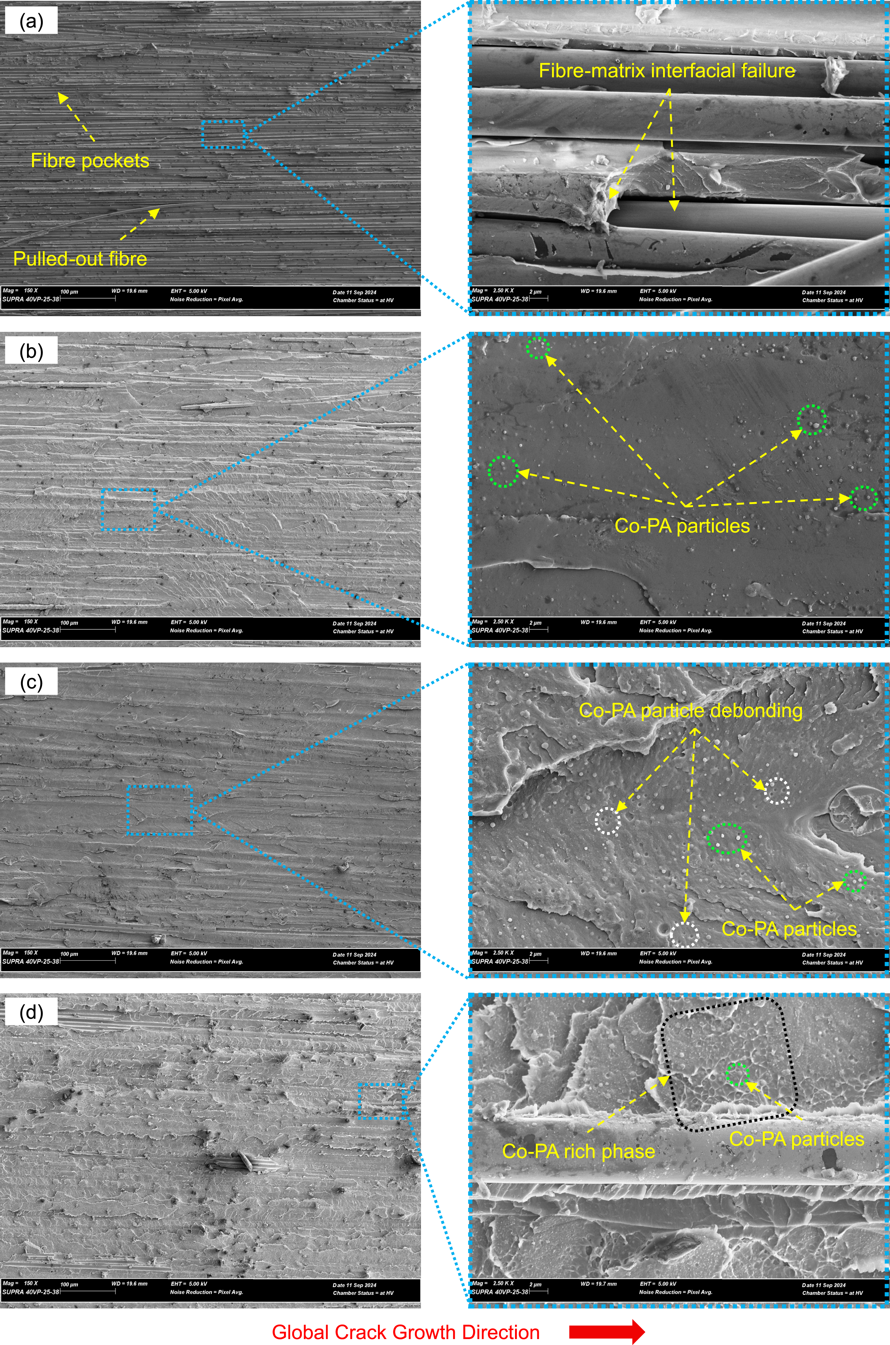
The melted particle dispersion was reasonably consistent across the 8 g/m2 laminate; however, it led to larger particle agglomerations across the 14 g/m2 laminate while finally forming a bi-continuous Co-PA phase across the 20 g/m2 laminate. Figure 11(d) highlights the bi-continuous Co-PA rich phase across specimens interleaved with the 20 g/m2 veil across the interlayer which ultimately resulted in the formation of thermoplastic particle agglomerations (encompassed by dotted black square). It was found that regions of low thermoplastic particle volume were also present, verifying that in some locations across the interlayer the onset of fibre bridging possibly occurred, albeit in low quantities, providing further explanation on the presence of a relatively ‘flat’ trend observed in the R-curve.
In Figure 11(b) to (d), there was consistent evidence of thermoplastic particle-resin interface failure across the crack plane of all interleaved samples identified in the form of concave dimples and craters over the fracture surface (indicated by dotted white circles). This strongly suggests that as the crack propagated, the presence of a weak particle-resin interface led to significant low-energy debonding of the Co-PA particles from the epoxy resin resulting in reductions in the fracture toughness. Due to the presence of a weak interface, there is a lack of thermoplastic ductility attributed to the elongation of particles across the crack plane during propagation. A weak interface requires a lower energy input to dissociate the particle from the epoxy matrix during crack propagation leading to reductions in the fracture toughness and in some instances a decrease in the stability of the crack, as was the case in this research. A similar failure mechanism was observed by Wang et al.
31
who found that debonding of Co-PA particles may result in a reduction of the fracture toughness where the particle-resin interfacial adhesion is weak. The proposed failure mechanisms resultant of the fractographic analysis for both virgin and interleaved laminate configurations are represented in Figure 12 and visualise the crack propagation pathway (solid red line) across the interlayer. Proposed crack pathway and failure mode for (a) Virgin, (b) 8 g/m2, (c) 14 g/m2, (d) 20 g/m2 laminate configurations under Mode-I loading conditions.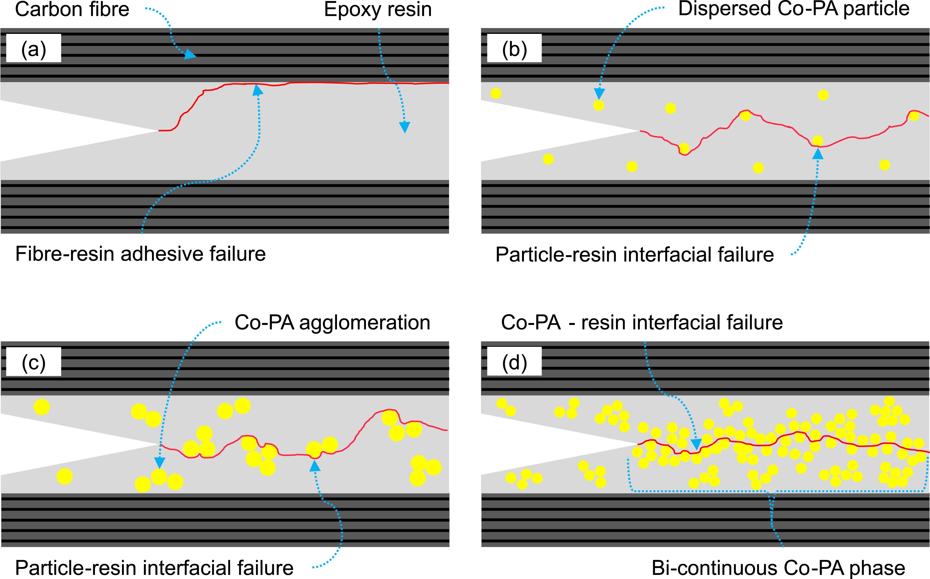
From the DCB tests and fractographic analysis, virgin specimens exhibit pure adhesive failure along the fibre-resin interface (Figure 12(a)). The presence of low-melt Co-PA non-woven veils at low areal densities (8 g/m2) leads to a reasonable distribution of thermoplastic particles across the interlaminar region (Figure 12(b)). However, due to the weak interfacial bonding between the Co-PA particles and epoxy resin in conjunction with a suppression of fibre bridging across the interlayer, there is a reduction in the overall fracture toughness of the laminate. As the veil density increases to 14 g/m2 and 20 g/m2, the formation of thermoplastic agglomerations also increase (Figure 12(c)) and eventually leads to the development of a bi-continuous phase (Figure 12(d)), further reducing the magnitude of GIC across the interleaved laminates owing to the ease of crack propagation across the larger particle-epoxy interface. Additional investigations into the use of low-melt Co-PA veils as interleaves within CF/EP composites should be conducted to further understand how the particle-resin adhesion impacts the fracture toughness of a CF/EP composite under Mode-I loading conditions. From this, studies on how the particle-resin adhesion can be improved, for example by means of surfactants to increase the binding surface energy of the veil and particles would prove beneficial for the implementation of such interleaves in aerospace applications.
Conclusions
This study aimed to explore the effects of low-melt copolyamide (Co-PA) veils on the Mode-I fracture toughness and consequent failure mechanisms on laminated CF/EP composites. The virgin laminates showed the highest Mode-I fracture toughness across all configurations with an average of 450 J/m2. The specimens interleaved with an 8 g/m2 veil saw a mild reduction in the Mode-I fracture toughness with an average decrease of 23%, while specimens containing 14 g/m2 and 20 g/m2 veils saw a larger reduction of 33% and 52% respectively. Fractographic analysis revealed the presence of inadequate interfacial adhesion between the Co-PA particles and epoxy resin creating an energetically favourable pathway for the crack to propagate. Evidence of particle debonding was also identified across the failure surface of all interleaved laminates which was the primary mechanism of failure. As well as this, the presence of Co-PA was found to inhibit the formation of carbon fibre bridging across the interlaminar zone leading to further reductions in the resultant fracture toughness of the interleaved laminates. The results of this research signify the importance of particle-resin adhesion with respect to the Mode-I fracture toughness of a laminate interleaved with meltable copolyamide veils.
Footnotes
Acknowledgments
This research was conducted within the Aerostructures Innovation Research Hub (AIR Hub), supported by the Victorian government under the Victorian Higher Education State Investment Fund (VHESIF). The authors acknowledge the support of the Swinburne/CSIRO Industry 4.0 Testlab in carrying out the research presented in this paper. The authors would like to acknowledge and thank Mohammad Ravandi for his technical support and Alex Cardew-Hall for his assistance with initial Mode-I testing.
Declaration of conflicting interest
The author(s) declared no potential conflicts of interest with respect to the research, authorship, and/or publication of this article.
Funding
This research was funded by the Victorian Higher Education State Investment Fund (VHESIF) through the Aerostructures Innovation Research Hub (AIR Hub)
Data Availability Statement
Data will be made available on request.