
Abstract
Carbon fiber reinforced thermoplastic composites are rapidly emerging as alternative materials for auto parts due to recyclability, excellent stiffness, and strength to weight ratio. In the present study, the influence of carbon fiber de-sizing on the structural and mechanical properties of the sized and de-sized Carbon Fiber Reinforced Polypropylene (CFPP) composites molded by the recently developed novel Direct Fiber Feeding Injection Molding technology was studied. The effect of carbon fiber de-sizing on the structural properties was studied from the fiber dispersion status, fiber orientation factor, fiber volume fraction, and the fiber length. The surface morphology of the sized and de-sized carbon fibers was studied from the Scanning Electron Microscopy (SEM) and Atomic Force Microscope images. The static mechanical properties were studied based on the tensile tests at different loading rate and temperature. The Dynamic Mechanical Analysis tests were conducted to analyze the dynamic viscoelastic behavior of the sized and de-sized CFPP composites. The SEM images were used to observe the failure mechanism. The preliminary results indicated that de-sized composites had better fiber dispersion as compared to the sized CFPP composites. It was found that de-sizing the carbon fiber surface does not significantly affect the carbon fiber length, fiber volume fraction, and fiber orientation in the CFPP composites. Also, the de-sized composites showed better static and thermodynamic mechanical properties caused by the enhanced fiber matrix interaction in CFPP composites as compared to the sized CFPP composites.
Keywords
Introduction
Due to the increasing demand for lighter, cheaper, recyclable, and reliable composite materials in the automobile industry, more attention is being paid to fiber reinforced thermoplastic composites (FRTPs), particularly, the carbon fiber reinforced thermoplastics (CFRTPs).1–7 The CFRTPs can well meet these demands due to their light weightiness, good mechanical properties, and reusability. However, the carbon fibers available in the market are usually coated with the sizing agents mostly suitable with the thermosetting resins.8,9 Therefore, the applied sizing agent on the carbon fiber (CF) surface is usually not very compatible with the thermoplastic resins. For example, the polypropylene (PP) does not have its own active groups to react with the functional groups present on the carbon fiber surface, which causes poor interface properties between the carbon fiber and polypropylene resin.10–13
Amongst the high efficiency molding methods to produce composite materials, the injection molding technology is a common technique which is being used to produce the plastic products from the 18th century.14–16 The FRTPs composite materials molded by the injection molding technology were generally produced by using the short-fiber reinforced thermoplastics (SFT) and long-fiber reinforced thermoplastics (LFT) pellets.17–19 However, the produced composite products had some major quality issues like gas-burn marks due to the presence of moisture, and the toxic gases inside the polymer melt solution. In addition, the pellets drying process caused an additional cost.20,21
The vent type injection molding technology was developed in Japan in the 1950s. 22 After its emergence, the vent-injection molding technology had been gaining a lot of attention due to its unique concept of a vent hole designed in the middle of the cylinder. The vent hole served multiple purposes: (i) the vent hole provided an exit to the toxic volatile gases and water vapors produced during the polymer melting process, which causes gas burns on the final products and clogging at the cavity area in the mold; (ii) it eliminated the pellet drying process which saved a lot of time, electricity, and equipment cost. However, this technology soon failed to gain wide acceptance in the industries because, along with the gases, the polymer resin also spilled out of the vent hole which caused troubles during bulk production. Until several years from now, it was reported that significant improvements in its specially designed screw and vent hole had successfully solved this problem.22,23
Based on the developed vent-injection molding technology, a new technology known as the Direct-Fiber-Feeding injection molding technology (DFFIM) was also proposed.24,25 In the DFFIM technology, the continuous fiber roving strands can be directly guided into vent of the devolatilizing unit of the injection barrel and then fed into the melt solution by the shearing motion of the screw during the plasticization process as shown in Figure 1. Therefore, there is no need to pre-cut the fiber roving into segments to make pellets and dry them prior to their feeding into the injection molding machine, which leads to lower electricity, equipment, and labor cost. Recently, researchers have tested the performance of different kind of composites molded by the DFFIM technology,23,25–28 to build the database in order to testify the performance of this newly emerged DFFIM technology over a wide range of polymer composites. On the other hand, the literature review revealed that in 1993, Truckenmueller and Fritz H. Gin
29
proposed a concept for the elimination of pellet making process and tried the Direct Incorporation of Continuous Fibers (DIF) into the melt solution through a vent hole by designing a mixing non-return-valve (LFMR). However, no further research work could be found in the literature about the DIF technology. It is said that the DIF technology failed because of the poor mechanical properties resulting from the bad fiber distribution in the composites. Direct fiber feeding injection molding process.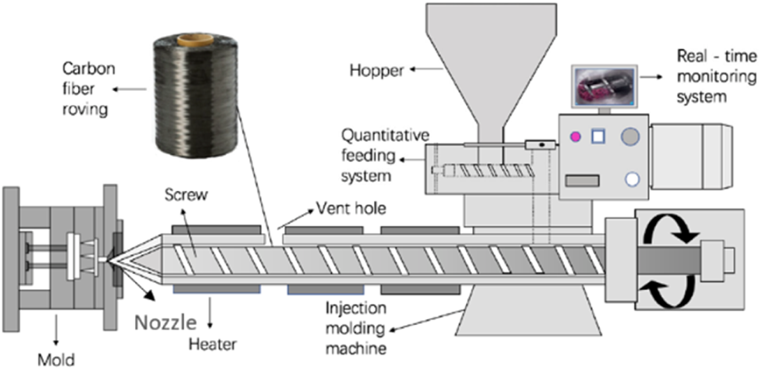
In the present study, an approach to achieve better fiber distribution and interface properties of carbon fiber reinforced polypropylene (CFPP) composites molded by DFFIM technology was considered. In order to study a suitable new sizing material, it should either be directly applied on the surface of the already sized carbon fiber or de-size the carbon fiber surface firstly and then apply the new sizing material on it. It is considered that applying the new sizing material on the already sized carbon fiber surface might alter the real significance of the new sizing material. Therefore, the sizing material from the CF surface should be removed firstly, the interaction of de-sized carbon fiber with the polypropylene resin should be studied, before the new sizing material is applied to the de-sized CF surface. Therefore, as a first step of the systemic research, the carbon fiber surface was de-sized by using the hot water to study its effect on the structural and mechanical properties of the de-sized CFPP composites, and compared with the originally sized CFPP composites. Their structural, static, and thermodynamic mechanical properties were investigated through different kinds of tests and discussed in detail.
Experimental details
Materials
In this study, the DFFIM technique was used to produce CFPP composites. The PAN based carbon fiber with epoxy sizing (Carbon Fiber Co., Ltd. under trade name SYT45S 12K, diameter; 7 μm) and the polypropylene pellets under trade name K4912 (melt flow rate; 12 g/10 min, melting temperature; 147°C, nominal strain at tensile fracture; 620%) supplied by Zhongfu Shenying, and Shanghai SECCO Petrochemical Co., Ltd were used, respectively. The carbon fiber content for both sized and de-sized composites was fixed at 20% by weight. The manufacturing parameters like molding temperature, barrel speed, and feeding rate were kept constant to do a reasonable analysis about the effect of sizing agent removal on the overall performance of the composites.
Carbon fiber de-sizing process
The carbon fibers were de-sized by using hot water as shown in Figure 2. An iron basin was filled up with water and placed on a heater to heat the water up to 70–80°C. Two guide rollers were installed inside the iron basin to completely dip the carbon fibers in the water and to provide a smooth passage to the carbon fibers. After water reached the set temperature, the carbon fibers were passed through the hot water at 0.8 m/min speed by using the guide rollers (about 20 s immersion time). The de-sized carbon fibers were dried at 100°C, collected at the other end, and tightly wound on a cone at the other end. Afterward, the dried fibers were introduced into the DFFIM machine to produce the CFPP composites. Schematic diagram of the carbon fiber de-sizing process.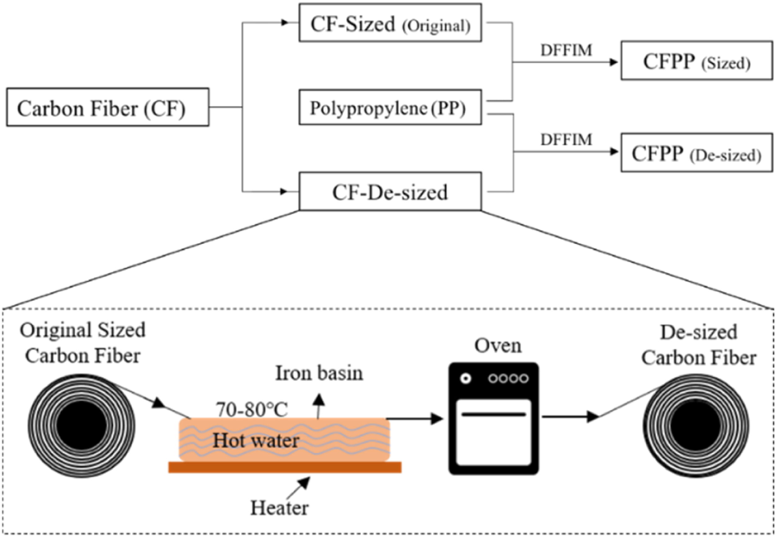
Specimen preparation
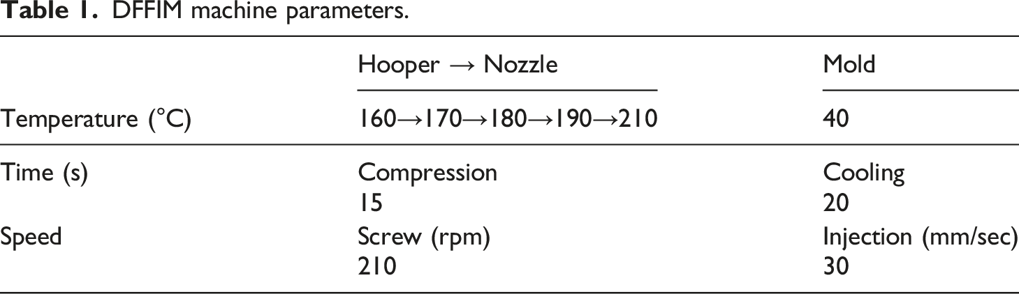
DFFIM machine parameters.
Testing method
Surface morphology
The effect of de-sizing on the carbon fiber surface was measured both qualitatively and quantitatively. The Scanning Electron Microscope (Hitachi flexSEM 1000, Model; SU1000) was used to observe the apparent surface characteristics (qualitative) of sized and de-sized carbon fibers. Similarly, the quantitative measurement of the surface roughness of sized and de-sized carbon fibers was determined from the Atomic Force Microscopic (AFM, Horiba AIST NT) images. Multiple scans were performed at different locations on the sized de-sized carbon fiber tow along the length and width direction. The average “Rq” and the “Ra” values were obtained from the test data and used for further evaluation.
Tensile test
In the present study, the INSTRON 5946 universal testing machine with the load capacity of 3 kN was used to test the tensile properties of CFPP composite. The machine was additionally equipped with INSTRON 3119-609 temperature control chamber which is capable of maintaining temperature in the range between −100°C and 350°C. The specimens were tested at three different constant crosshead speeds of 0.2, 2, and 20 mm/min at five different temperatures, that is, 25, 40, 60, 80, and 100°C. The tensile strength, modulus, and the maximum load at failure of the specimens were calculated according to the ASTM D 638-10. Each test specimen was clamped in the machine jaws and preheated for 10 min before applying the load. After applying the load, the load and temperature were maintained at the pre-defined values until the specimen failed. After specimen failure, the test was stopped and the broken specimen was taken out of the machine for post-observation. Three samples were tested for each type of test.
Scanning Electron Microscopy
In order to investigate the fiber-resin interface properties, the scanning electron microscope (used in Surface Morphology.) was used to observe the fractured surface of the CFPP specimens. Three samples were tested for each type and the fractured surface of each specimen was gold-ion sputtered prior to the observation.
Fiber dispersion status
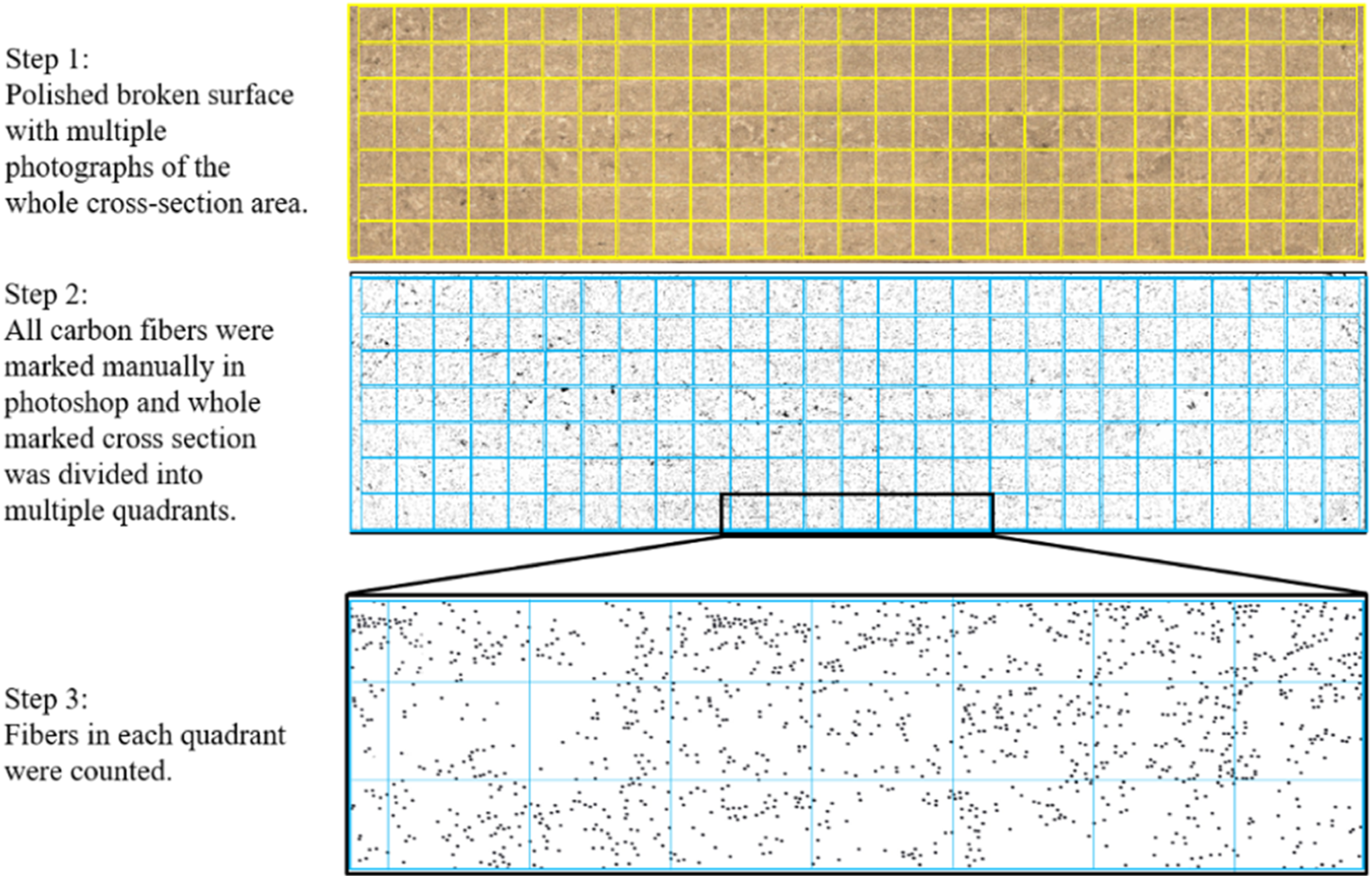
The fiber distribution index (FDI) is commonly used for quantitatively evaluating the fiber dispersion status. The schematic diagram of the whole calculation process is shown in Figure 3. The middle portion of the broken specimens followed by the tensile test were cut and cast in an epoxy resin. After curing, the specimens were polished with sand papers of various roughness (coarse to finest) to get a smooth polished surface. The polished specimens were observed under a digital microscope (Keyence, Model: VHX-5000). To ensure the accuracy of the results, all carbon fibers were traced and marked with hand (almost 0.1 million dots altogether for both samples) in adobe photoshop to create a schematic image of the carbon fibers’ position in the composites. The marked cross-section was divided into Fiber distribution index (FDI) calculation process.

A perfectly homogenous fiber distribution is represented by FDI = 1, whereas, FDI = 0 indicates completely inhomogeneous fiber distribution as shown in Figure 4. Schematic representation of homogeneous (a) and inhomogeneous (b) fiber distribution.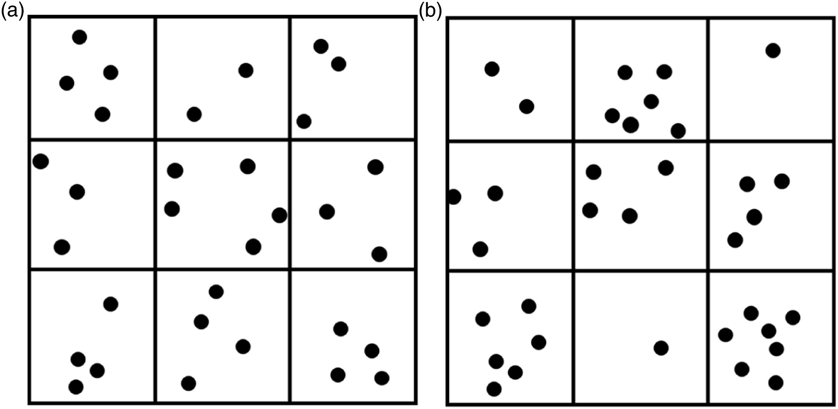
Fiber orientation factor
To find out the fiber orientation factor, the same digital microscopy images from Fiber Dispersion Status were used. The composite’s cross-sectional area shows circular and elliptical-shaped carbon fibers. The circular fibers represent a 0° fiber orientation angle, whereas the elliptical fibers represent different angle, with respect to the melt flow direction. The fiber orientation angle, The schematic diagram of the fiber orientation measurement process.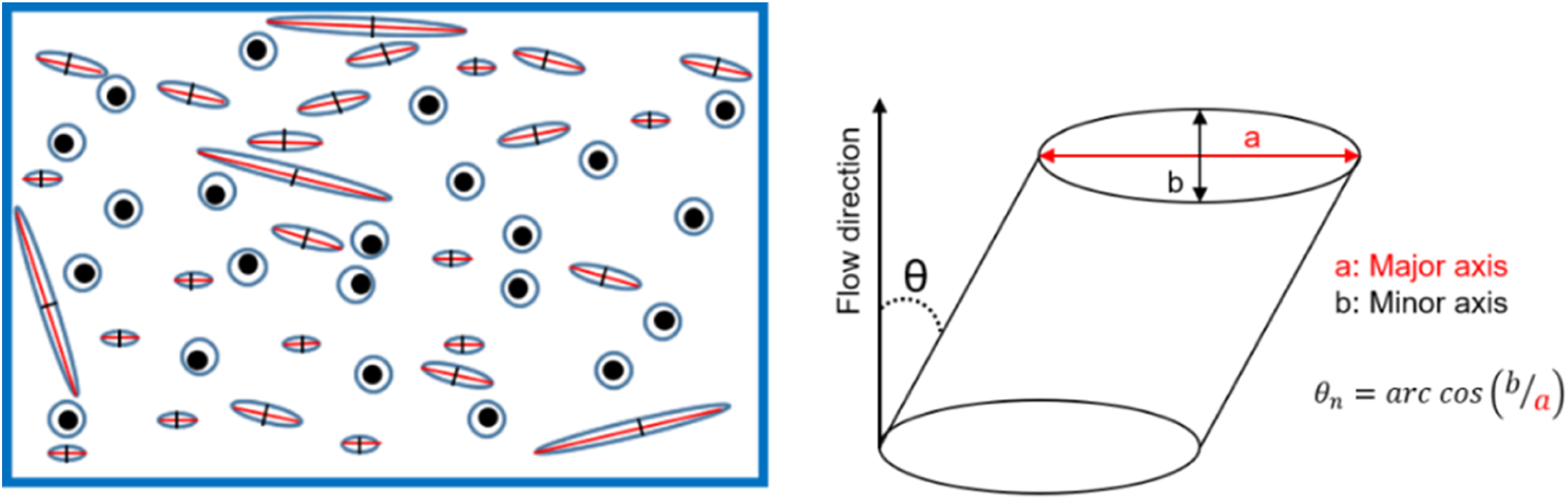
The circular fibers were considered as making 0° angle (parallel to the melt flow direction), whereas the orientation angle, 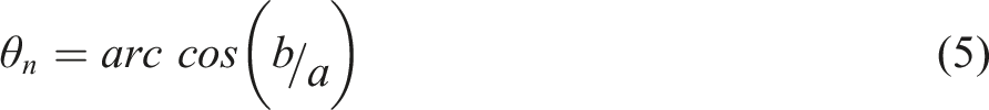
The overall fiber orientation factor, 
Fiber length measurement
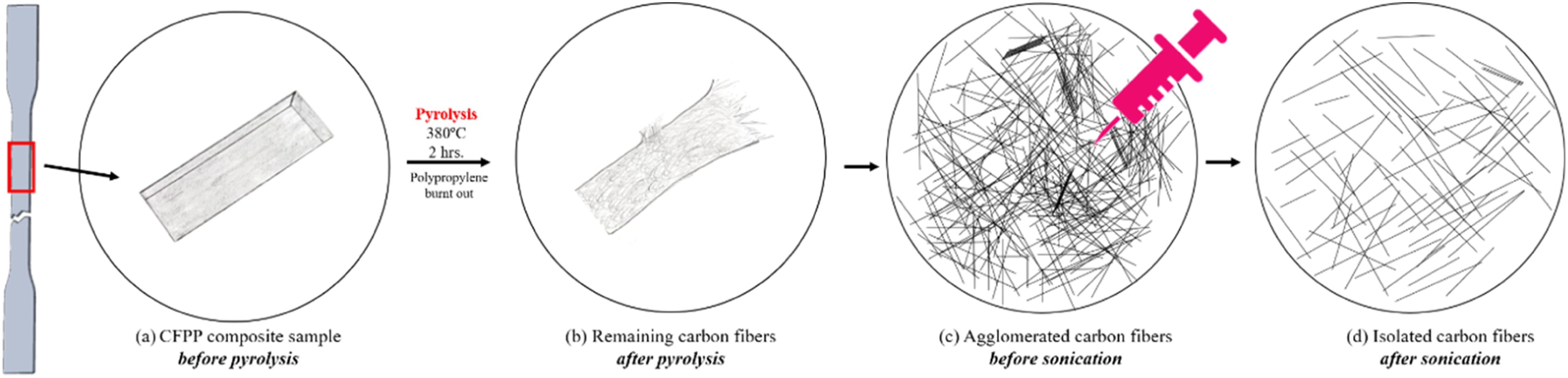
The fiber length measurement process is shown in Figure 6. The sized and de-sized CFPP broken specimens followed by the tensile tests were cut into 2.5 cm long bars, placed in the crucible cups, and pyrolyzed in a muffle furnace at 380°C for 2 h. The polypropylene resin was burnt out leaving behind the carbon fibers. A small bunch of carbon fibers were carefully picked up from different skin and core regions with the help of tweezers to have a general representation of the fibers across the whole cross-section area, and cast on a glass plate. To disperse the agglomerated fibers from each other, the distilled water was slowly sprayed on them with the help of a syringe. The unique syringe dispersion method was used to avoid the fiber breakage which might occur if tweezers were used to separate them. The circular plates filled with the distilled water and carbon fibers were tightly sealed with a plastic foil and placed in the water tub of an ultrasonic machine (JAC, Model: KODO 4020) for sonication at 60°C for 2 hours to further isolate the fibers from each other. After sonication process, the plastic foil was removed and the glass plates were placed in an oven at 100°C for 2 hours to dry out the water, and isolated carbon fibers were left at the bottom of the plate. Finally, these fibers were observed under an optical microscope. The length of almost 1200 fibers taken from three different samples (around 400 from each) of each type, that is, sized and de-sized was calculated in Fiji software and their weight-average fiber length, Fiber length measurement process.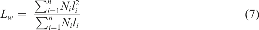
Fiber volume fraction
The fiber volume fraction, 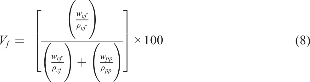
Dynamic mechanical analysis
Dynamic viscoelastic properties of sized and de-sized CFPP composites were studied from the dynamic mechanical analysis at frequency sweep mode. TA instruments’ Q-800 was used to run the Dynamic mechanical analysis (DMA) tests in the tensile mode in accordance with the ASTM D5026. For frequency sweep mode, test scans were performed from 0.1 to 100 Hz between −60 and +30°C at 10°C temperature ramp rate. Isothermal soak time at each temperature was selected as 3 min for proper heat distribution across the whole cross-section of the material under consideration.
Results and discussion
Effect of de-sizing on the carbon fiber surface morphology
The SEM photographs of the originally sized and de-sized (hot water treated) carbon fiber surface are shown in Figure 7(a) and (b), respectively. The SEM photographs show that the hot water de-sizing changed the surface topography of the sized carbon fibers on a micro-scale. It was observed that removing the sizing material gives rise to certain surface roughness and produces longitudinal streaks on the de-sized carbon fibers’ surface. However, it remains undiscovered that how much sizing agent was removed from the carbon fiber surface. Technically speaking, it is difficult to find the exact amount of the sizing agent removed from the carbon fiber surface because the sizing agent is usually applied less than 1–2% by weight of the carbon fiber with surface thickness confined to a few nanometers. The SEM and AFM photographs of the sized (a, c) and de-sized (b, d) carbon fiber surface, respectively.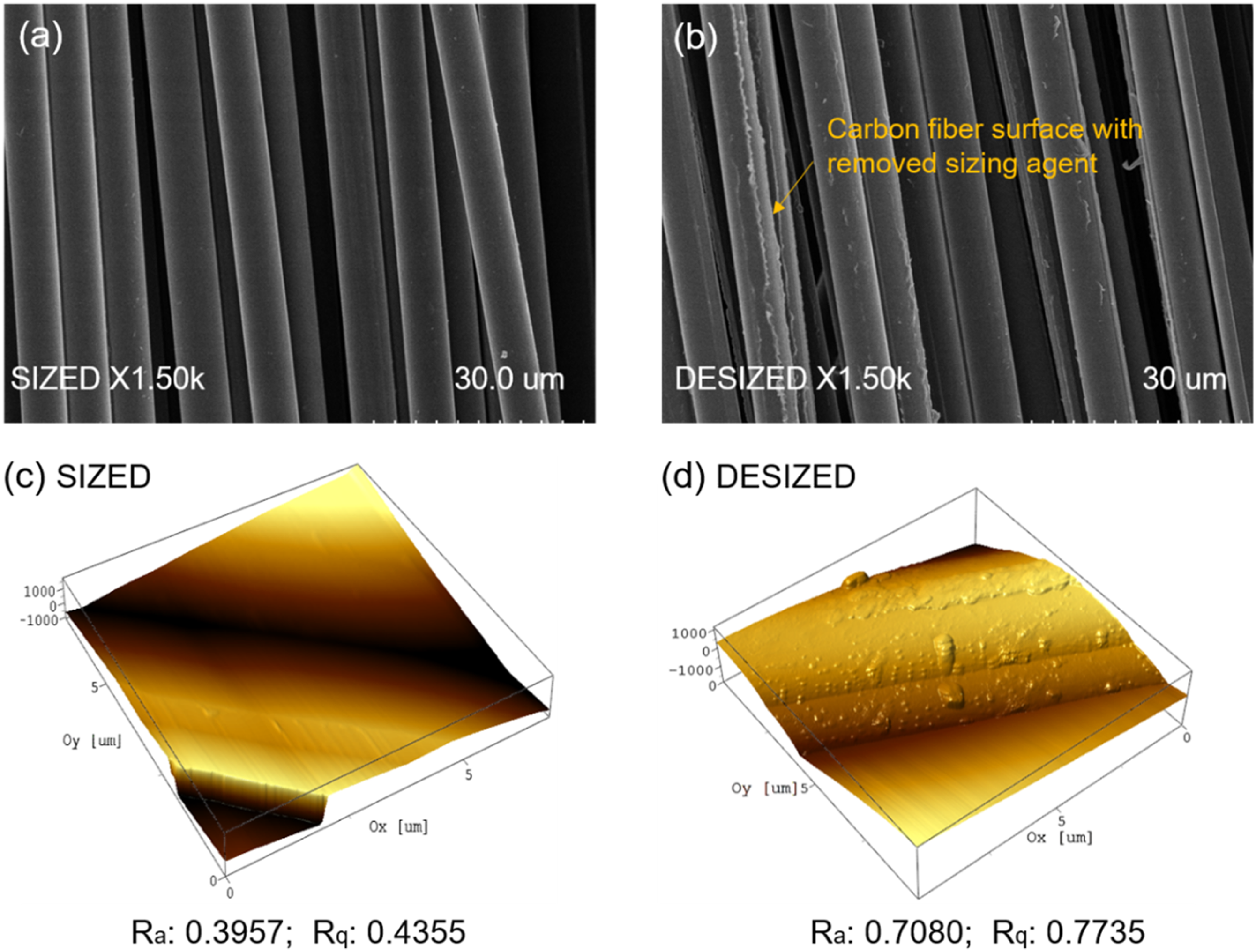
However, another indirect method (Atomic Force Microscopy, AFM) can be used to estimate the presence/absence of sizing agent by measuring the surface roughness value before and after the removal of the sizing agent. The Atomic Force Microscope (AFM) is a very sophisticated technology which can measure the surface roughness with great accuracy. Generally, “R q ” and “R a ” values from the AFM test data are used to analyze the surface roughness of the specimens. “R a ” is the arithmetic average of the absolute values of the surface height deviations measured from the mean plane. Whereas, “R q ” is the root mean square average of height deviation taken from the mean image data plane.
The AFM images of the sized and de-sized carbon fiber surface are presented in Figure 7(c) and (d), respectively. For sized CF, the fiber surface is very smooth with no grooves and height peaks. After de-sizing the carbon fiber surface with hot water, some streaks and bulged segments can be clearly seen on the fiber surface. It can be clearly seen that the “R a ” and “R q ” values of de-sized carbon fiber are higher than the sized carbon fiber. This indicates the higher surface roughness which facilitates mechanical interlocking between the fiber and matrix, and could lead to the better interfacial adhesion. If this difference is represented as the proportion of the sizing agent removal, it can be estimated that nearly 1/4th of the sizing agent was partially/fully removed.
It was noted that the carbon fibers were not completely de-sized by using the hot water technique as shown in Figure 7(b) and (d). Some fibers remained unaffected which is possibly due to the following two reasons: (i) during the hot-water de-sizing process, the water could not make significant surface contact with all carbon fibers’ surface due to the bundling of the sized carbon fibers or (ii) the sizing agent on the carbon fiber surface had a unique chemical nature. In general, the solvent extraction techniques break the physical bonds while chemical bonds remain intact. It is thus expected that the physiosorbed parts of the sizing layer were removed while the dominantly chemically bound sizing material remained. Similar findings were reported by various authors31,32 who used solvent extraction techniques to completely de-size the carbon fiber surface, however, which could not be achieved. It suggests that instead of using toxic and expensive chemicals to de-size the carbon fiber surface, environment-friendly hot-water treatment can also be used to remove the sizing agent to a reasonable extent.
Basic mechanical properties
Static tensile properties
The basic tensile properties were evaluated at room temperature, that is, 25°C at 0.2 mm per minute tensile speed. The load-bearing capabilities, tensile stress, and modulus of de-sized composites were found to be higher than the sized CFPP composites. The de-sized CFPP composites showed 17.8% higher load-bearing capabilities (1727 ± 86.7 N) as compared to the sized composites (1466.56 ± 112 N). Similarly, the tensile modulus of de-sized composites (2.99 ± 0.05 GPa) showed an increment of 24.5% than the sized composites (2.40 ± 0.02 GPa). The tensile strength of de-sized composites (59.33 ± 3.71 MPa) also remained higher than the sized composites (47.51 ± 1.11 MPa) by 24.87% approximately. The detailed analysis for this behavior is discussed in Scanning Electron Microscopic Analysis.
Scanning electron microscopic analysis
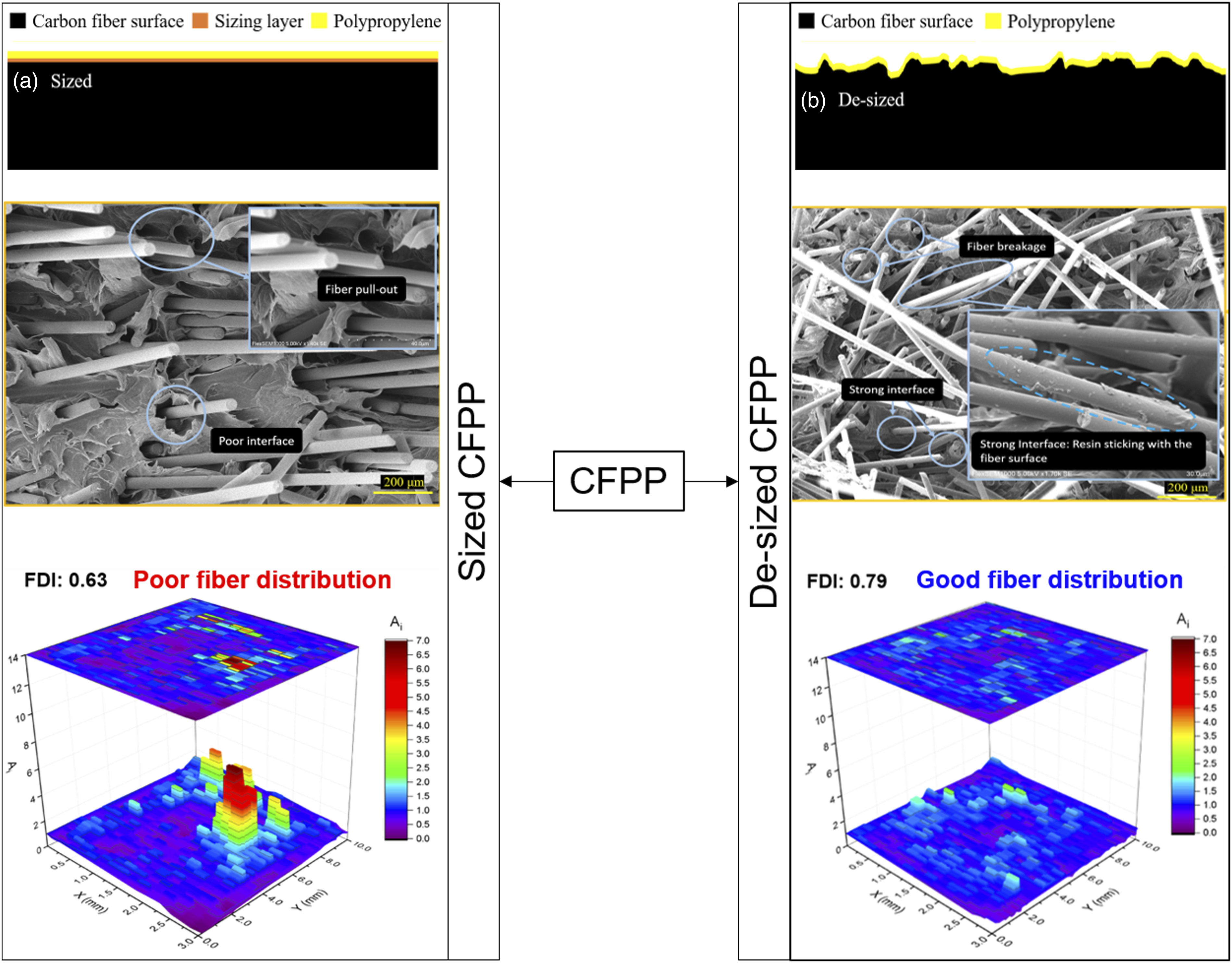
In order to investigate the main factors for the above-mentioned variation in the tensile properties of both composites, the fractured surface of the composite specimens followed by the tensile test was observed under a scanning electron microscope. It was noted that the sized CFPP specimens tend to show poor interface properties as shown in Figure 8(a). The fibers and resin were weakly bonded with each other and huge gaps were found between them. Due to the weaker interface properties, several fibers were pulled out of the matrix resin as the load was applied. The disjoint of fibers from the resin inherited poor load-transfer capabilities between reinforcement and matrix, which ultimately led to the lower mechanical properties of the sized composites. SEM images of sized (a) and de-sized (b) CFPP composites at 25°C and 0.2 mm/min speed.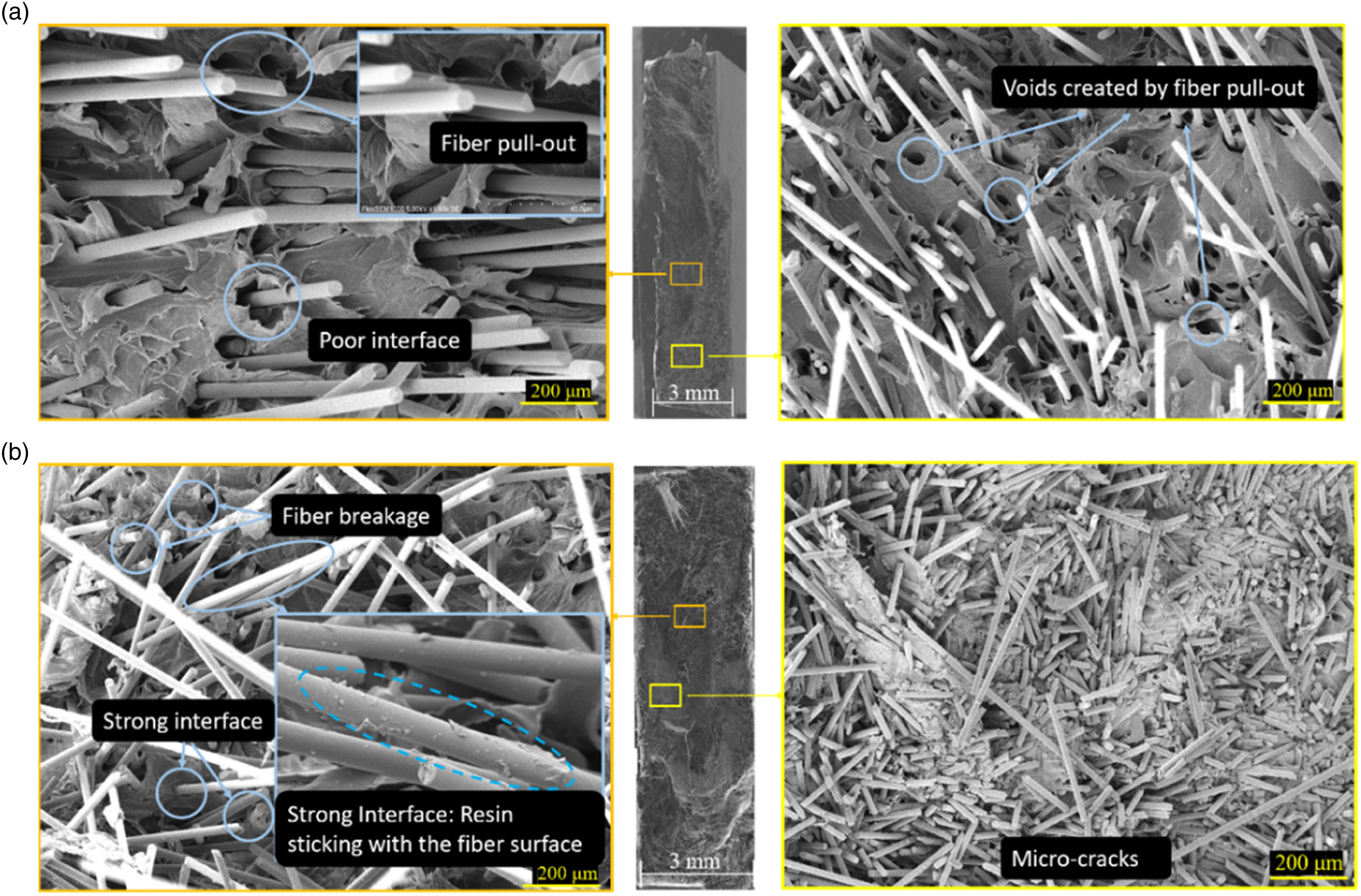
On the other hand, de-sized specimens showed comparatively less fiber pull-out, fewer voids, and a stronger fiber-resin interface as shown in Figure 8(b). The resin remained stuck to the fiber surface even after the fibers were pulled out of the resin, which indicates the improved bonding between fiber and resin. Additionally, some micro-fractures of carbon fibers were also found in the failed specimen that is also due to the fact that PP resin did not release the fiber immediately as load was applied on the material. It is considered that the above-mentioned factors contributed to the overall higher mechanical properties of de-sized composites, that is, stronger fiber-resin interface, less fiber pull-out, and micro-factures.
Fiber distribution status
A projection map of the fiber distribution status is shown in Figure 9. It can be clearly seen that the de-sized CFPP composites show better fiber distribution than the sized CFPP composites. From the 3D projection map, multiple peaks can be visualized for the sized CFPP composites which indicate the fiber agglomeration. The fiber agglomeration area in sized composites is much larger than the de-sized CFPP composites. Fiber distribution projection map across the whole cross-section of sized (a) and de-sized (b) CFPP composites.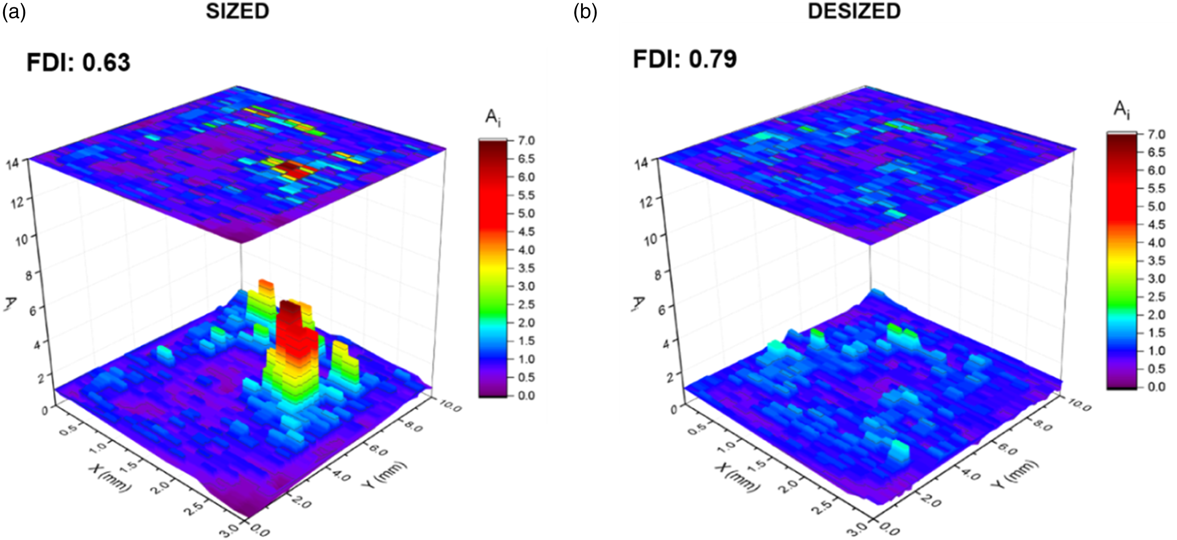
The value of counted fiber ratio,
In general, apart from protecting the fiber surface and increasing its wettability, the sizing material is also used to keep the fibers bound with each other to control fibers’ entanglement with each other or disallow their isolation from the main strand before their end-use.
33
It is considered that during the de-sizing process, a significant amount of sizing material was removed from the carbon fiber surface which could have isolated the fibers from each other (by creating empty spaces between them) prior to their feeding in the DFFIM machine as shown in Figure 10. This phenomenon has possibly caused less agglomeration in the de-sized CFPP composites. Schematic diagram of the carbon fiber tow before (a) and after (b) hot-water de-sizing.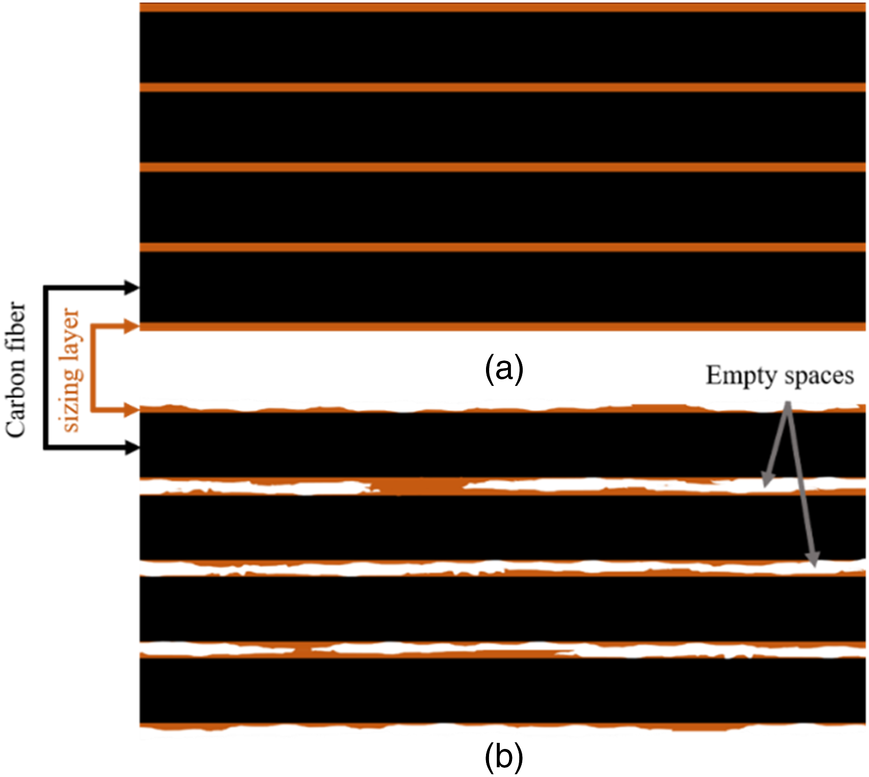
Fiber orientation status
The fiber orientation angle and fiber orientation factor of sized and de-sized CFPP composites.
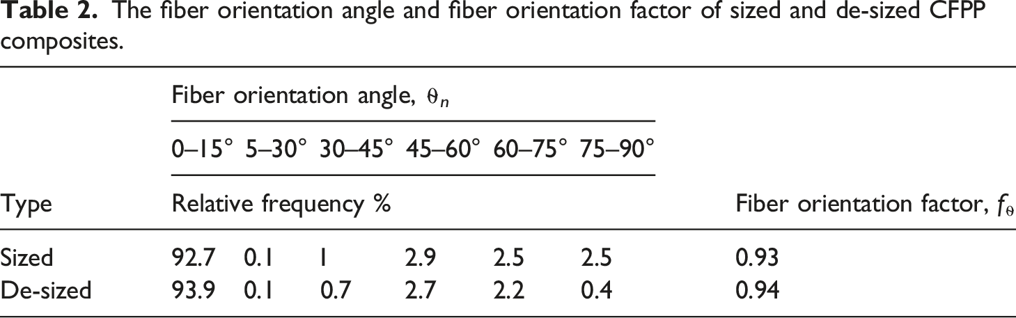
From Table 2, it can be seen that the frequency of the fiber orientation angle,
Effect of de-sizing on the fiber volume fraction and fiber length
The fiber volume fraction and average fiber length of sized and de-sized CFPP composites.
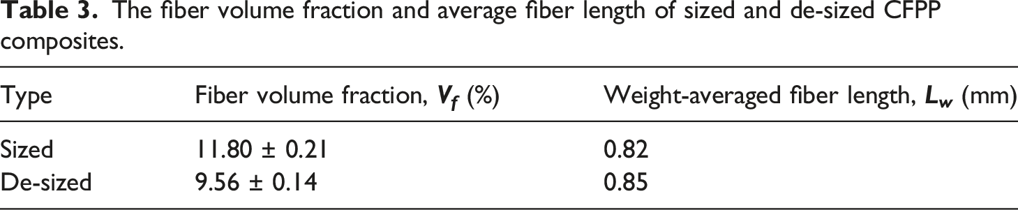
The carbon fiber length distribution across the whole cross-section of the sized and de-sized CFPP composites is shown in Figure 11. The weight-average fiber length, The relative frequency (a), and the cumulative frequency (b) of the carbon fiber length distribution in sized and de-sized CFPP composites.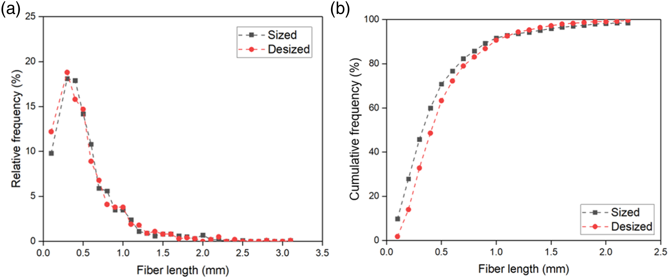
Effect of temperature and speed on the static mechanical properties of sized and de-sized CFPP composites
Load-displacement curves of sized and de-sized CFPP specimens
The load-displacement curves of sized and de-sized CFPP specimens measured at different temperatures and loading rates are shown in Figure 12 and the elongation at break values are listed in Table 4. The load-bearing capability of the de-sized composites was found to be higher than the sized CFPP composites under the same experimental conditions. Load-displacement curves of sized (a–c) and de-sized (d–f) CFPP composites at different loading rates and experimental temperature. Mechanical properties of sized and de-sized CFPP composites at different loading rate and temperature. %* represents the percent difference of the values between the sized and de-sized composite.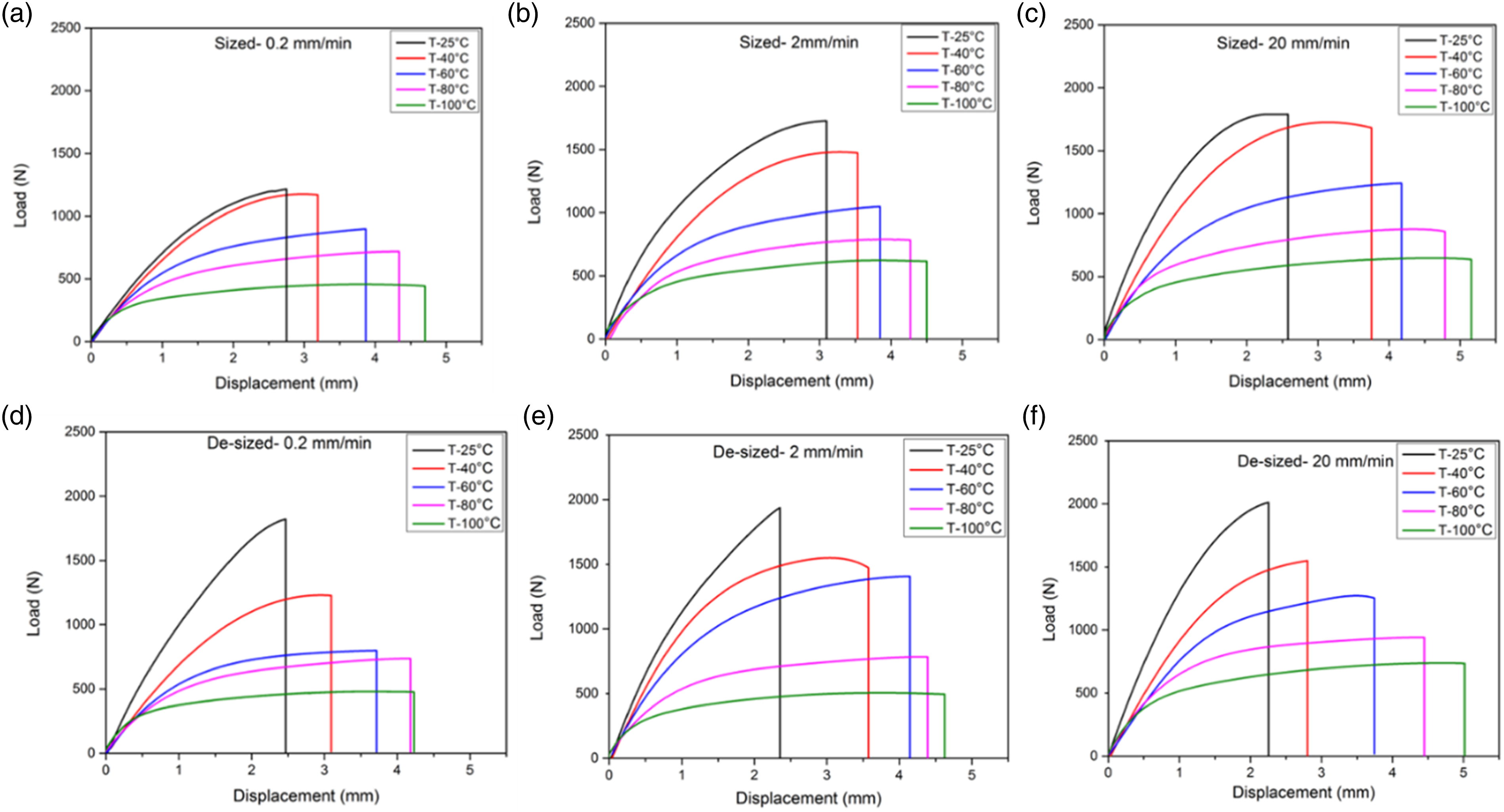
The failure displacement (elongation at break) of de-sized composites is lower than that of the sized CFPP composites at a given test speed and temperature. For example, at 0.2 mm/min test speed and 25°C temperature, the elongation at break for the de-sized composites is 10% lower than the sized CFPP composites. The average percent decrease value for the elongation at break is shown in Table 4. A few negative values are possibly caused by the instrument error. The decrease in the failure displacement and increase in the load is a result in the improvement of the stiffness and strength of the de-sized composites which is caused by an embrittlement effect due to the strong interface between the de-sized carbon fiber and polypropylene resin. Some researchers have established the cause of this embrittlement effect as matrix crack formation at the ends of the reinforced fibers.36,37 As the strain increases, cracks gradually form at the ends of the shorter fibers. In the beginning, this cracking can be adjusted by transferring loads to the adjoining fibers that bridge the cracked area. During final failure, cracking occurs across the weakest section of the specimen. A critical level is reached when the local fibers and matrix can no longer bear the excessive load.
Effect of loading rate on the tensile strength and modulus of sized and de-sized CFPP composites
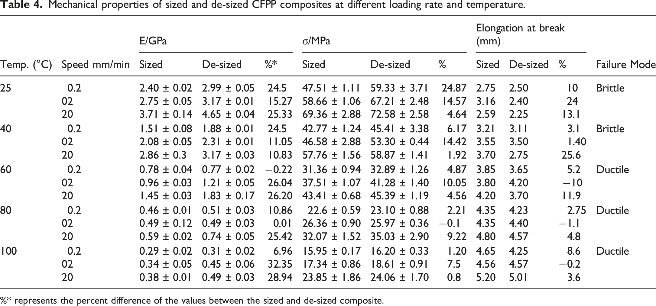
The line graphs shown in Figure 13 compare the tensile modulus and tensile strength of sized and de-sized CFPP composites at three different loading rates, that is, 0.2, 2, and 20 mm/min, whereas the average increase or decrease in their mechanical properties is outlined in Table 4. It was observed that the tensile modulus and tensile strength for both sized and de-sized CFPP composites increased with the increasing loading rate. The tensile modulus and tensile strength of the sized and de-sized CFPP composites.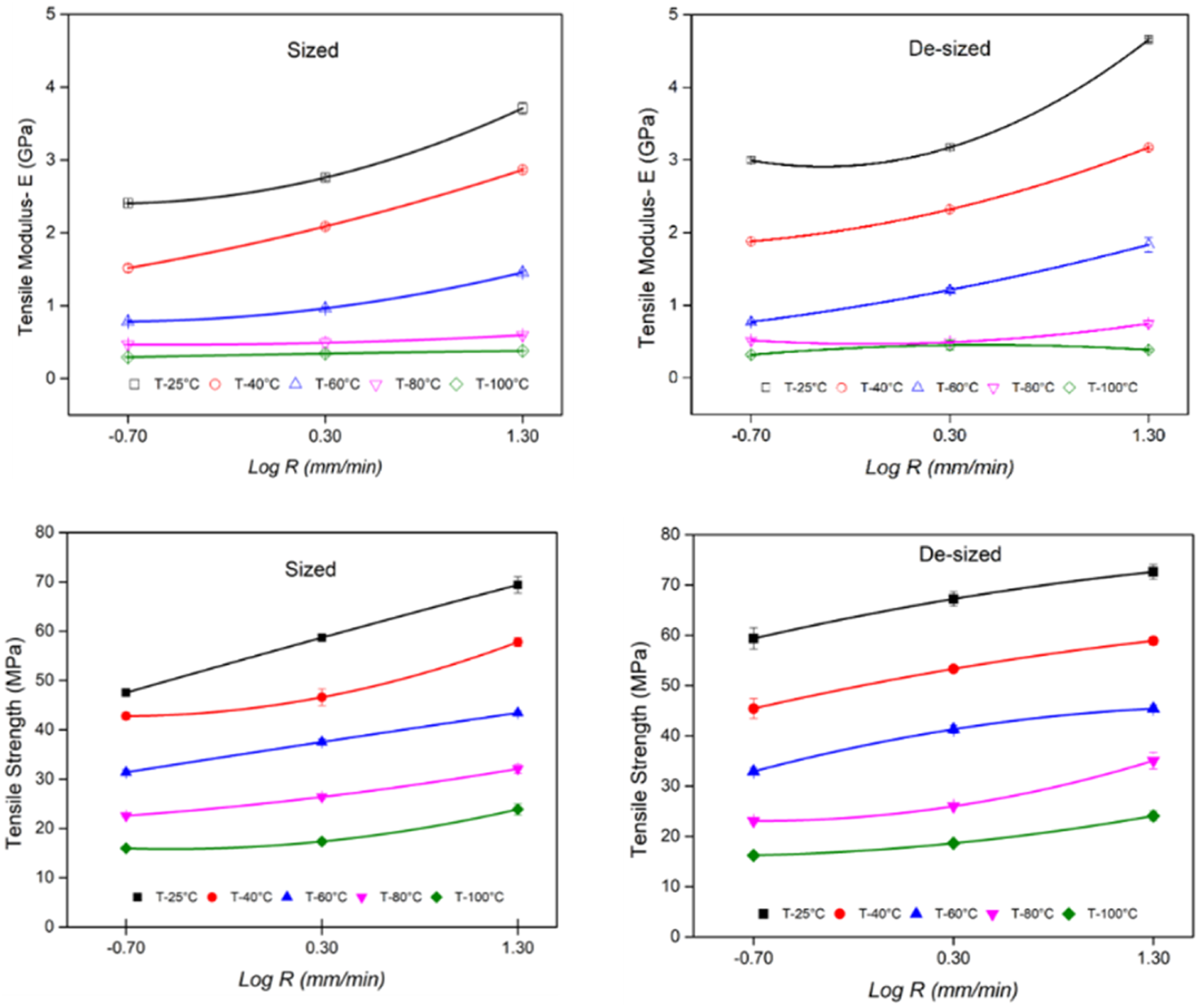
As shown in Table 4, the average tensile modulus of sized CFPP composites increased by 19.87% as the loading rate was increased from 0.2 to 2 mm/min which is however still lower than that of de-sized composites which increased by 25.45%. As the speed was further increased from 2 to 20 mm/min, the average tensile modulus of sized composites rose up by 31.12% but the average tensile modulus of de-sized specimens still remained comparatively higher at 39.01%. Similarly, with the loading rate variation from 0.2 to 20 mm/min, the average increment in tensile modulus of sized specimens was 57.83%, whereas this value increased to about 73% for de-sized specimens. Overall, it was observed that the tensile modulus of sized composites remained 26.6% (on average) lower than the de-sized CFPP composites at all loading rates.
The effect of different loading rates on the tensile strength of sized and de-sized CFPP composites also had a similar effect on the tensile modulus, that is, the tensile strength increased with the increasing loading rate. The tensile strength increased by 15.46%, 23.43%, and 42.17% on average for sized specimens and 16.69%, 18.51%, and 38.03% for de-sized specimens as the loading rate was increased from 0.2 to 2, and 20 mm/min, respectively.
The reason for lower tensile properties at a lower loading rate is due to the fact that at a lower loading rate, the polymer chains of the polypropylene are stretched along the applied stress direction and have enough time to rearrange themselves. This movement of polymer chains initiates some small cracks inside the structure which possibly start from the weaker areas of the material. This phenomenon causes some small defects in the material which reduces the load-bearing capabilities of the overall structure and ultimately results in the lower tensile strength. 38 On the other hand, at a higher loading rate, the material does not have sufficient time to generate small cracks and defects inside the structure and the whole material fails abruptly thus leading to comparatively higher mechanical properties. As it is known from the above discussion that de-sized CFPP had better structural properties, which led to the higher tensile properties as compared to the sized CFPP composites.
Effect of temperature on the tensile modulus and strength of the sized and de-sized CFPP composites
The line graphs in Figure 14 compare the effect of experimental temperature on the tensile properties of sized and de-sized CFPP composites and their respective values are shown in Table 4. Overall, it can be seen that the tensile modulus and tensile strength of sized and de-sized composites stood highest at the lowest temperature, that is, 25°C which steadily dropped down as the temperature rose higher. Tensile strength and tensile modulus of sized and de-sized CFPP composites at the different experimental temperature.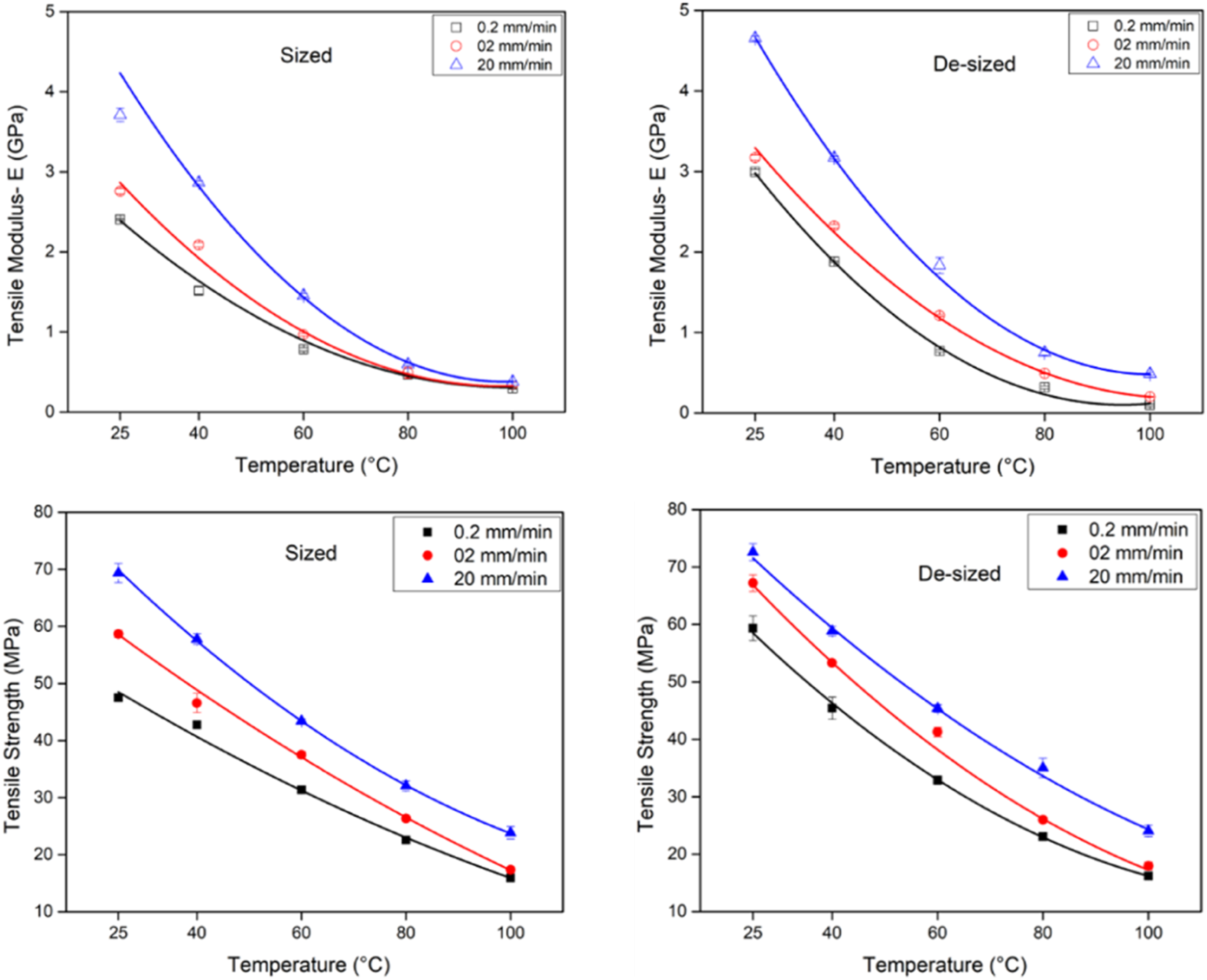
It can be seen from Table 4 that tensile modulus of sized CFPP composites decreased by 28.1%, 64.5%, 82.3%, and 88.4%, whereas the de-sized CFPP composites decreased by 32%, 65.5%, 83.8%, and 88.3% as the temperature increased from 25°C to 40°C, 60°C, 80°C, and 100°C, respectively. Similarly, the tensile strength also decreased with increasing temperature, as shown in Table 4. The tensile strength of sized and de-sized composites decreased by almost 15.7% and 21% as temperature increased from 25°C to 40°C. As the temperature rose from 25°C to 60°C, 80°C, and 100°C, the tensile strength was further reduced by 36.1%, 53.8%, and 67.4% for the sized composites, whereas of sized composites further, whereas 39.9%, 57.7% and 70.4% for the de-sized CFPP composites, respectively.
The temperature has a significant effect on the tensile properties of sized and de-sized composites. The reason for the higher thermal stability of both sized and de-sized specimens at lower temperature is due to the less or restricted mobility of polymers chains of PP resin. However, at elevated temperature, PP resin starts softening, (increases the polymer chain’s mobility, which weakens the fiber-resin interface properties. Due to the weak interface, the uneven and poor load transfer take place between fiber and resin which results in the lower tensile properties of the overall composite.
Generally, it was observed that the de-sized CFPP composites have shown comparatively better tensile properties. As carbon fiber was relatively strongly bonded with PP resin in the de-sized composites, therefore, it is considered that the heat was evenly distributed between the matrix and resin due to more surface area contact points which resulted in better tensile properties. T. A. Sebaey reported that more work is required to overcome the bonding forces at fiber-resin interface, when strongly bonded fiber-resin is stretched in the applied force direction. 39 However, in sized specimens, this heat transfer process might not have even distribution due to the huge gaps at fiber and resin interface region. It is the same phenomenon which have possibly resulted in the lower strength of sized CFPP specimens as there were large gaps at carbon fiber and polypropylene interface region, whereas de-sized specimens had less gaps. Thus, more work was required to overcome the bonding forces in de-sized composites which resulted in the higher tensile modulus and strength of the overall composite material.
The fracture behavior of sized and de-sized CFPP specimens at higher temperatures and higher loading rates is shown in Figure 15. A molten resin can be clearly seen covering most of the fiber surface and making it harder to observe the fiber-resin interface. From Figure 15(a), for sized specimens at a higher loading rate, fiber pull-out was a dominating factor which created many hollow spaces in the composite. The already poor interface between the sized carbon fiber and PP further weakens due to the softening of PP at elevated temperature. Therefore, as the specimen experienced tension at a higher temperature, the fibers were easily pulled out of the swamp-like PP resin. On contrary, clearer fiber breakages were witnessed in de-sized specimens as shown in Figure 15(b) which were, however, fewer in the sized specimens. The possible reason for fiber breakage is due to the strong resistance offered by the stronger interface to the applied load. SEM images of (a) sized (b) de-sized CFPP composites at 60°C and 20 mm/min speed.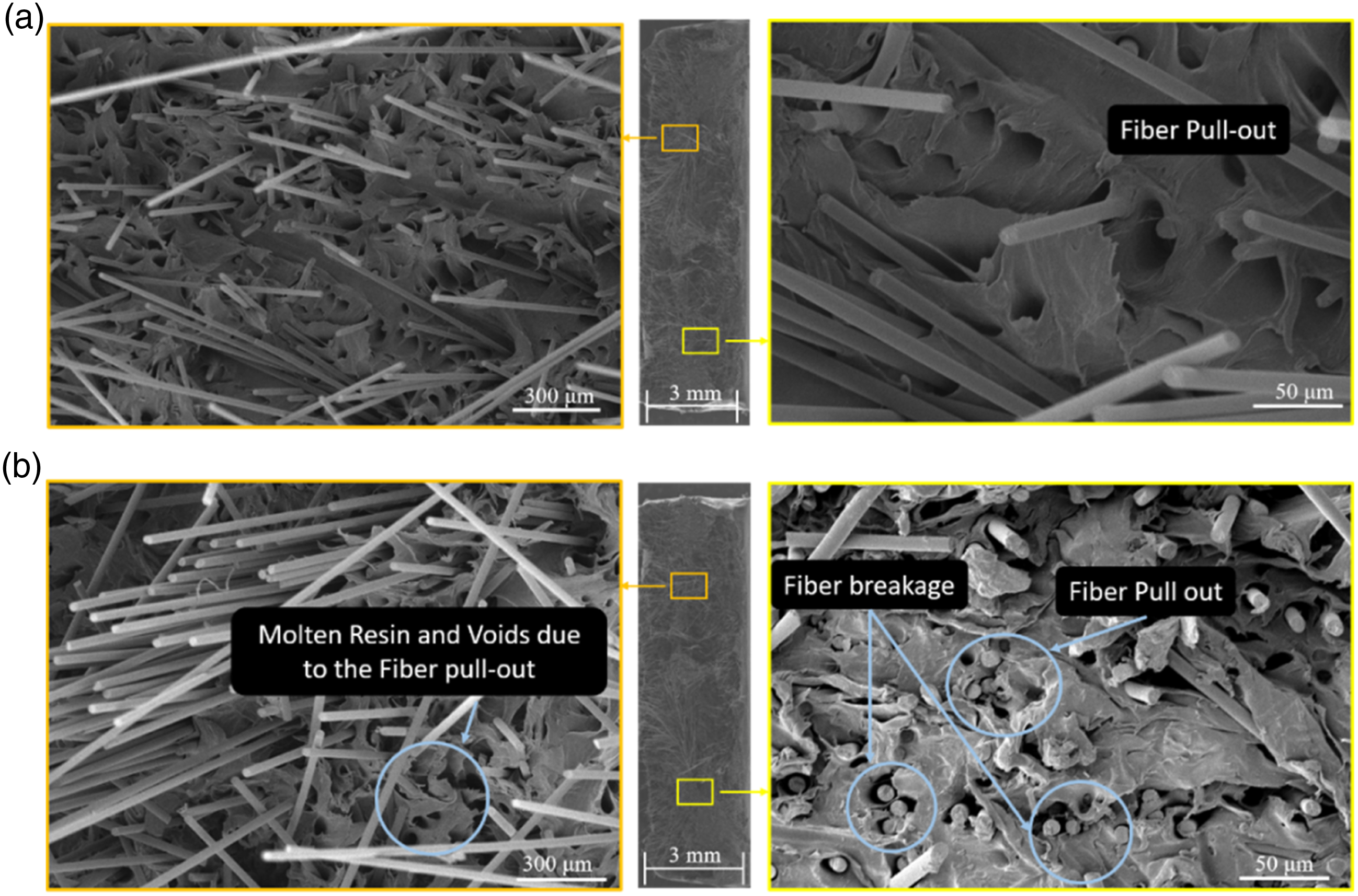
Dynamic mechanical analysis
Apart from the static viscoelastic behavior, the dynamic viscoelastic behavior of the sized and de-sized CFPP composites was also characterized by the DMA tests. According to the TTS (Time-temperature Superposition) principle, the dynamic viscoelastic behavior of the polymer composites over a broad range of frequency can be generated by shifting the viscoelastic response of the given material at different constant temperatures along the log scale of the frequency.40–42 In the present study, frequency sweep tests were performed on sized and de-sized CFPP composites from 0.1 to 100 Hz at a temperature between −60°C and +30°C as shown in Figure 16. The storage modulus of sized and de-sized CFPP composites at different frequencies and temperature (a, c) and their representative master curves (b, d), respectively.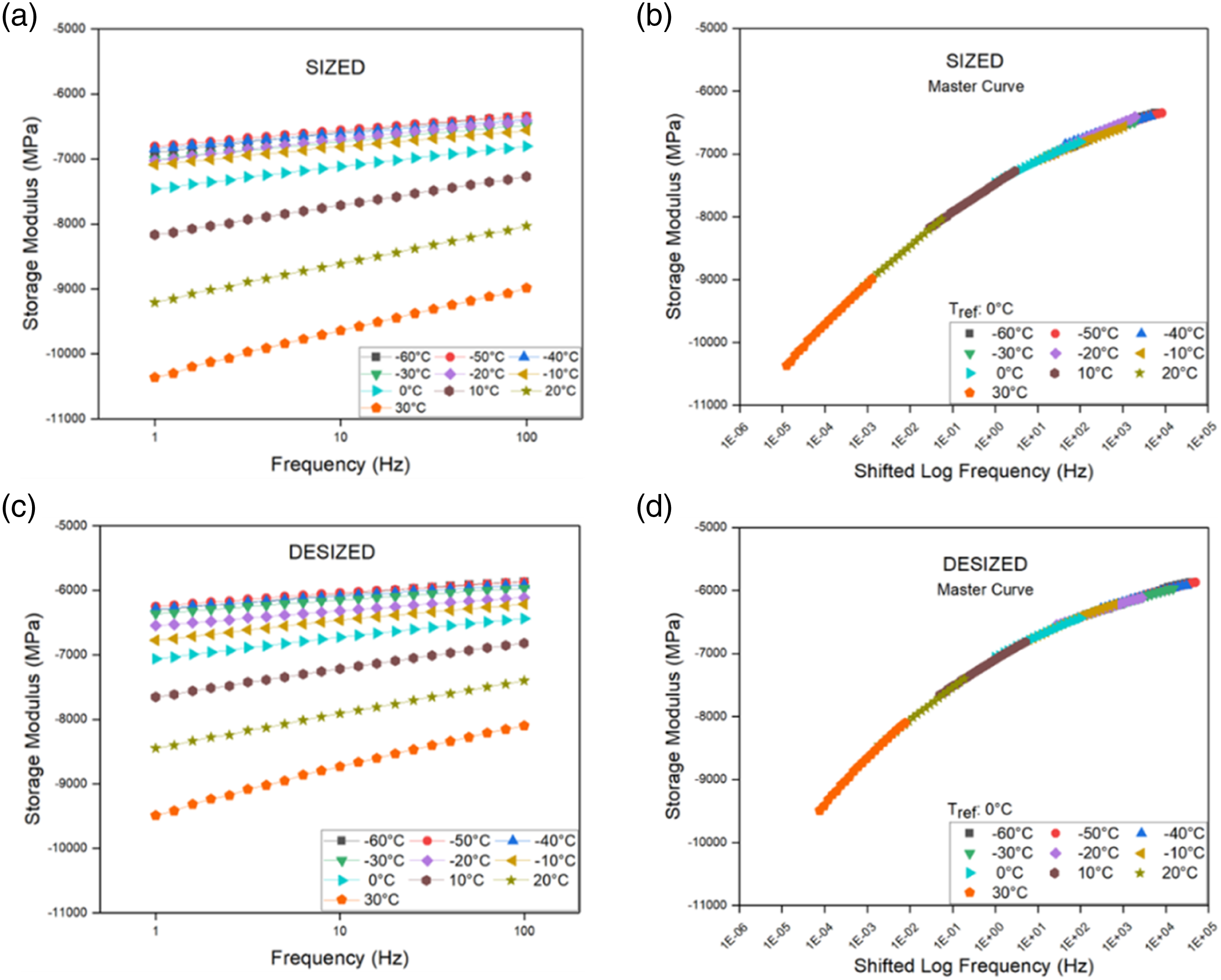
The storage modulus of sized and de-sized CFPP composites as a function of the frequency and temperature is shown in Figure 16(a) and (c). According to the TTS principle, the storage modulus-frequency curves at different temperatures can be shifted along the log scale frequency to construct a master curve of the storage modulus at any reference temperature as shown in Figure 16(b) and (d). The shift factors were used to shift the short-term curves to obtain the long-term master curve. The 0°C temperature was chosen as the reference temperature in the following study. A comparison of the master curves of the frequency-dependent storage modulus of the sized and de-sized CFPP composites is shown in Figure 17. The storage modulus for both composites increase with the increased frequency. This is due to the fact that at low frequency, time is large enough to unravel the polymer chains’ entanglements, so a large amount of relaxation occur which results in a lower value of storage modulus. However, when a polymer sample is deformed at a large frequency, the entanglement chains do not have sufficient time to relax, so the modulus goes up. The fitted master curves of the sized and de-sized CFPP composites.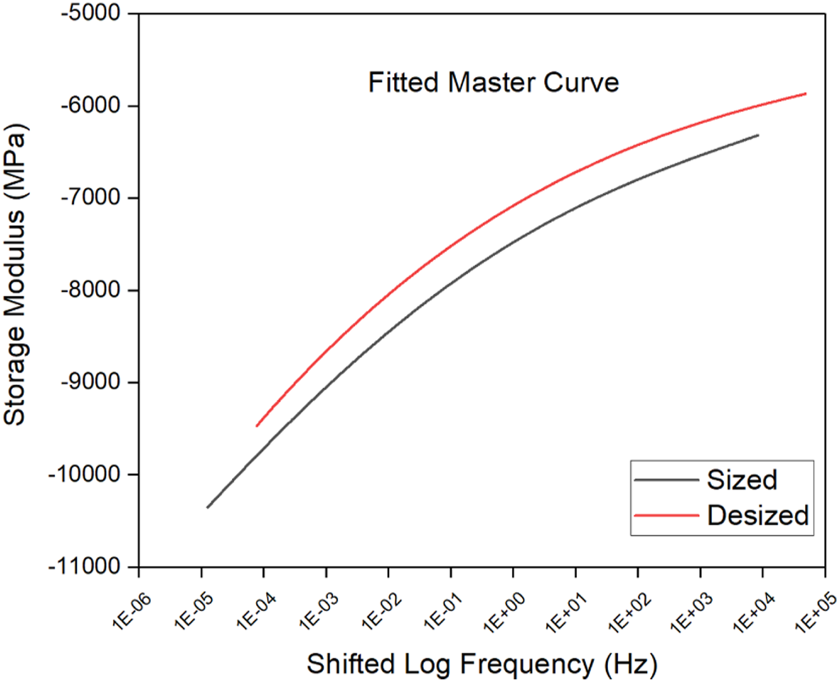
It can be seen from Figure 17 that the shifted storage modulus of de-sized composites over a broader range of frequency is higher than the sized CFPP composites. This indicates that the interfacial adhesion between the de-sized carbon fiber and polypropylene is stronger than the sized carbon fiber and polypropylene in the sized composites.
Nursel. D
33
reported that the interfacial adhesion between carbon fibers and a matrix resin can be enhanced by increasing the surface area (increasing roughness) which may provide more points of contact between the fiber and matrix resin. As known from the previous experimental results that the de-sized carbon fibers had a comparatively rough surface, thereby had more points of contact between the fiber’s surface and polypropylene as shown in Figure 18. The free movement of polymer chain segments is difficult in the presence of too many contact points between the carbon fiber surface and polypropylene resin, which leads to a higher storage modulus as compared to the sized CFPP composites. In the future work, more investigations would be done to have the detailed analysis of the fiber-matrix interface between the polypropylene, and carbon fiber with and without the sizing material on its surface, which is unknown yet, and remains confidential by the carbon fiber manufacturer. The comparison of the surface area contact between the sized (a) and de-sized (b) carbon fiber and polypropylene resin.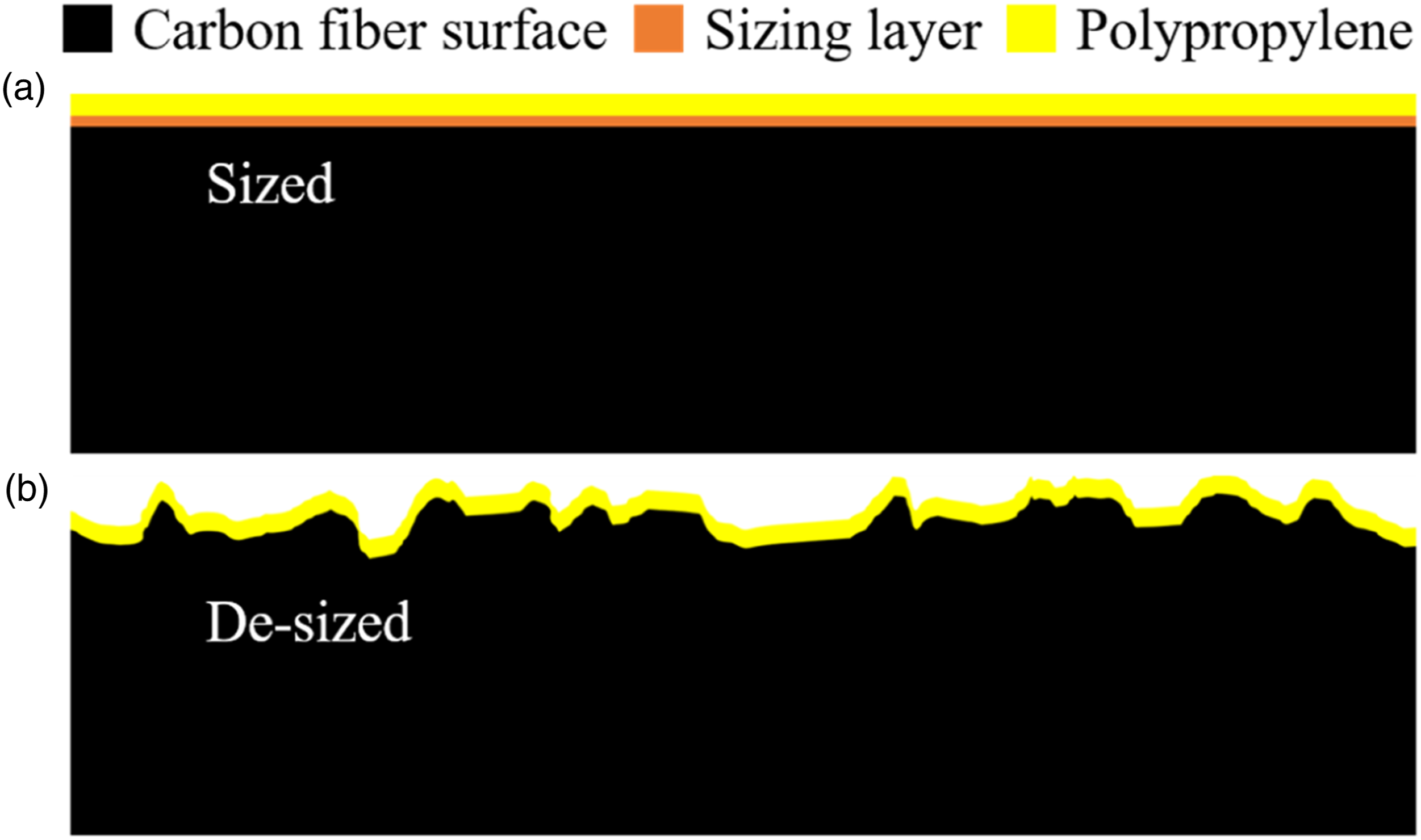
Conclusions
In the present study, the structural and mechanical properties of the sized and de-sized CFPP composites molded by the DFFIM technology were analyzed. The following conclusions are obtained from the study: 1. The surface characterization of the carbon fibers showed that the hot water de-sizing method can remove the sizing agent to a reasonable extent which is still good enough to produce CFPP composites with good mechanical properties. 2. The de-sized CFPP composites had better fiber distribution as compared to the sized CFPP composites. The lower FDI value of sized CFPP composites is caused by the fiber agglomeration which led to the uneven fiber distribution, whereas, the higher FDI values of de-sized CFPP composites is due to the isolation of carbon fibers which led to the better fiber distribution across the whole cross-section area. 3. The weigh-averaged length of the carbon fiber in sized and de-sized CFPP composites remained identical which indicates that regardless of the carbon fiber sizing agent removal, the DFFIM technology can still produce the CFPP composites with similar fiber length. 4. The removal of sizing agent from the carbon fiber surface did not have any significant effect on the carbon fiber orientation in the CFPP composites. The fiber orientation factor for sized and de-sized CFPP composites was found to be almost similar. 5. The de-sized CFPP composites showed better static and thermodynamic mechanical properties as compared to the sized CFPP composites. The SEM images showed that the de-sized CFPP composites had better fiber-matrix interface and less fiber pull-out, whereas the sized CFPP composites exhibited poor fiber-matrix interface, more voids, and higher fiber pull-out which led to a big difference in their mechanical performance.
Footnotes
Acknowledgements
The authors gratefully acknowledge the technological assistance provided by Ni-Hon Yuki Co., Ltd. Japan.
Funding
The author(s) disclosed receipt of the following financial support for the research, authorship, and/or publication of this article: This research was supported by the Open Project Program of Key Laboratory of Yarn Materials Forming and Composite Processing Technology of Zhejiang Province (No. MTC2021-06)