Soft-ballistic sub-laminate (SBSL) made from ultra-high molecular weight polyethylene (UHMWPE) fibers in [0/90] stacking sequence are the building block of a multi-layer soft-ballistic armor pack (SBAP, aka Soft Armor). A systematic study of the perforation dynamics of a single layer SBSL and several multi-layer SBAPs (2, 3, 4, 8, 16, 24, 32 layers) is presented for the first time in the literature. A previously validated finite element model of transverse impact on a single layer is used to study the perforation mechanics of multi-layer SBAPs with friction between individual layers. Following the classical definition of ballistic limit velocity, a minimum perforation velocity has been determined for free-standing single layer SBSL and multi-layer SBAPs. For the multi-layer SBAPs, complete perforations have been identified as progressive perforation of individual layers through the thickness. The minimum perforation velocities of multi-layer SBAPS is linear with the areal density for the eight (8) layer target and thicker. Large deformation behavior and perforation mechanics of the SBAPs is discussed in detail.
A body armor system is essential for the protection of soldiers from high velocity projectile impacts,1–6 which comprises three major components (i) a hard armor plate (HAP) as the strike face, (ii) a hard ballistic soft composite laminate (HBSCL) as a backing to the HAP,3,7–12 and (iii) a soft armor pack (SAP) or insert (SAI) within a nylon bag; integrated in a polyester garment.1 Focus of the present paper is the soft armor pack (SAP) or soft ballistic armor pack (SBAP). In general, the SAP/SBAP component of the body armor system may include multiple layers of (a) 2D woven fabric stacked together with or without shear thickening fluid (STF),4–6,13–16 (b) 2D woven fabric with or without through-thickness stitching,14 (c) 2D [0/90] soft ballistic sub-laminate (SBSL) made from unidirectional laminae,17 or (d) 3D woven fabrics.18,19 Perforation mechanics of multiple layers 2D [0/90] UHMWPE soft ballistic sub-laminate (SBSL) of finite size under projectile impact is of great importance for understanding the response of soft ballistic armor pack (SBAP, aka Soft Armor Pack, SAP).17,20,21 The UHMWPE material investigated in this study is Dyneema® SK76 fiber impregnated with a polyurethane resin. This material is commercially available as a single sub-laminate comprised of two individual layers that are consolidated into a single sheet of material with a [0/90] stacking sequence. While hard ballistic soft composite laminates (HBSCL) are generally manufactured by hot press compression molding at 267°F (131°C) and at 3000 psi (207 bar ∼ 20.7 MPa),22 the manufacturing process for the single layer [0/90] SBSL is a trade secret. Soft armor made from this material is advertised to be 35% lighter than aramid materials for equivalent ballistic performance (DSM Dyneema® website [https://www.dsm.com/dyneema]). There are several review articles,1,4–6 on the soft body armor which provide the overall aspects of soft body armor technology and the progress made so far. There is a good body of literature on HBSCL,7,9–11,22–24 woven fabric based SAP with and without shear thickening fluid.14–16,25,26 However, ballistic performance of soft body armor pack (SBAP/SAP) is not available in the open literature because of the sensitive nature of the data. There is also limited information published on perforation mechanics of multi-layer 2D [0/90] soft-ballistic armor pack (SBAP) which is the motivation for this study.
In our previous paper,17 a single [0/90] sub-laminate of Dyneema®SK76/PU27–33 subjected to transverse impact was modeled using a layered shell element with a [0/90] stacking sequence in LS-DYNA. Each layer of the SBSL sub-laminate was treated as a transversely isotropic uni-directional composite in the shell element. The [0/90] SBSL model was validated for mesh sensitivity, axial wave velocity a0, and cone wave velocity ; with a one-dimensional (1D) theory34–38 and a two-dimensional (2D) membrane theory39–43 of dynamic deformation in domains of infinite dimension (Figure 1), details of which can be found in Haque et al.17
Nomenclature for Phoenix and Porwal (P&P, 2003) 2D-Membrane theory for isotropic materials along with the nomenclature for 1D-Fiber theory. Implosion wave speed , Young’s modulus , Density , 1D cone wave velocity , and implosion strain , Constant impact velocity of the projectile VP.
The schematic diagram and nomenclature of 1D fiber theory and 2D membrane theory of transverse impact is presented in Figure 1. Upon constant velocity transverse impact on a 1D isotropic fiber or a 2D isotropic membrane, an axial implosion wave propagates along the in-plane directions with an implosion wave velocity a0. Behind the implosion wave, a much slower transverse deformation cone develops and the edge of the cone wave “k” propagates with a cone wave velocity , which is a function of constant projectile speed VP (equations show in Figure 1 title). These theories have been used to validate the FE model in Haque et al.,17 and have been used in simulating the dynamic deformation and perforation behavior of the single layer SBSL of finite in-plane dimensions. An important finding was that under the transverse impact of a right circular cylinder (RCC) projectile on a semi-infinite [0/90] SBSL membrane, a diamond shaped cone wave is generated with a cone wave velocity starting at the 1D value, , which increased non-linearly with time along the primary material axes (fiber direction in the [0] or [90] layers) up to a plateau value. A finite size SBSL shows large deformation with several deformation mechanisms: (i) edge pull-in, (ii) crease formation, (iii) folding, and (iv) dishing. For a single layer SBSL of in-plane dimensions , perforation is found to occur at a minimum perforation velocity of 136 m/s under the impact of a 12.7 mm right circular cylinder (RCC) projectile of mass . At higher impact velocities, the peak perforation resistance force was found to be constant.
Based on this validated finite element (FE) model described in Haque et al.,17 we compare results from (i) large deformation and perforation behavior of the single layer SBSL, (ii) the perforation mechanics of soft ballistic armor packs (SBAP) consisting of 2 layers (2L), 3 layers (3L), 4 layers (4L), 8 layers (8L), 16 layers (16L), 24 layers (24L), and 32 layers (32L) of the [0/90] SK76/PU SBSL using the explicit finite element (FE) code LS-DYNA. While the stacking sequences for the various cases are not symmetric, this practically poses no issues, since the present study only considers transverse impact on multiple [0/90] single layer SBSLs loosely stacked together without any consolidations. A systematic study is conducted to identify the dynamic deformation and perforation mechanics and layer interactions of multi-layer SBAP of finite in-plane dimensions with free standing boundary conditions.
Finite element modeling of soft ballistic sub-laminate (SBSL) and armor pack (SBAP)
A single [0/90] soft-ballistic sub-laminate (SBSL) is considered our baseline for comparison to multi-layer response. The SBSL is of length 360 mm and width 360 mm in the XY plane having, thickness 0.127 mm, and mass 15.97 g. The center of the sub-laminate is located at the origin (Figure 2(a)). In Haque et al.,17 a mesh sensitivity analysis has been performed using four different mesh sizes, i.e. 0.50 mm, 1.00 mm, 1.5 mm, and 2.00 mm. In the mesh sensitivity analysis, axial displacements of points A, B, and C (Figure 2(a)); impact contact force and the rigid body velocity of the projectile has been compared which shows the minimum mesh size for identical predictions is 1 mm. This mesh size is then used to validate the FE model with 1D fiber and 2D membrane theories (Figure 1, P&P 2003) for isotropic materials; results of which show good match between the theory and FE results. The validated isotropic FE model is then adopted to study the transverse impact on [0/90] orthotropic membrane which demonstrated that the deformation of orthotropic membrane is significantly different than isotropic membrane, yet providing similar solutions to kink wave speed. Following this validated FE model of Haque et al.,17 a mesh size of 1 mm has been chosen in the present analysis. Layered shell element type 16 has been used in conjunction with *PART_COMPOSITE option of LS-DYNA in defining the [0/90] layer orientations. Transversely isotropic properties of uni-directional (UD) Dyneema® SK76/Polyurethane soft-ballistic lamina17 is used as the input to the *MAT_ENHANCED_COMPOSITE_DAMAGE model (MAT_054) for both the [0] and [90] laminas of the [0/90] SBSL, and is presented in Table 1.
Geometric dimensions and the FE Model. (a) Geometric dimensions of the UHMWPE sub-laminate and coordinate definitions (b) X-section of the 8L-SBAP model impacted with a 12.70 mm RCC projectile.
Transversely isotropic properties of uni-directional (UD) Dyneema® SK76/Polyurethane soft-ballistic lamina.17
Density, ,
Fiber volume fraction,
a
, MPa
, b
0.970
0.80
9781.85
2880
0.03103
52.05
92.814
0.507
0.507
0.188
0.169
0.188
0.303
0.303
0.4993
0.0017
0.0017
0.4993
a Axial wave speed along material direction 1, .
b Characteristic time of a SBSL of dimension :
Nomenclature:—Axial moduli; —Shear moduli; —Poisson’s ratio, 1, 2, 3; 1, 2, 3; —Tensile strength and —Tensile failure strain along material direction 1.
A right circular cylinder (RCC) projectile of diameter 12.7 mm and mass 12.61 g is used, and the projectile material is considered rigid. Multiple layers of the 1L-SBSL has been stacked together with a gap of 0.003 mm (to facilitate numerical contact) between each SBSL layers to generate 2L, 3L, 4L, 8L, 16L, 24L, and 32L SBAPs. Figure 2(b) shows half of the FE model of the 8L-SBAP and the 12.7 mm RCC projectile. The mass of the single layer SBSL and multilayer SBAPs (MC) and the ratio of the SBSL/SBAPs to the projectile mass () is presented in Table 2.
Mass properties of 1L-SBSL and nL-SBAPs (n = 2, 3, 4, 8, 16, 24, 32). Dimensions 360 mm, SBSL thickness 0.127 mm, Density 0.97 , Projectile mass 12.6052 g, Projectile diameter 12.7 mm.
SBSL/SBAP
Layer mass, , g
Mass ratio,
1L-SBSL
15.97
1.267
0.441
2L-SBAP
31.94
3.534
0.283
3L-SBAP
47.91
3.800
0.208
4L-SBAP
63.88
5.068
0.165
8L-SBAP
127.72
10.133
0.090
16L-SBAP
255.45
20.265
0.047
24L-SBAP
383.17
30.398
0.032
32L-SBAP
510.89
40.530
0.024
Body armor application of SBAP on human thorax is generally modeled with clay. Because we are not modeling the clay support (left as future work), free standing boundary conditions (i.e., unconstrained boundaries) are imposed on the FE model (Figure 2) of the 1L-SBSL and on the nL-SBAPs (n = 2, 3, 4, 8, 16, 24, 32). The segment-based (SOFT = 2) eroding single surface contact definition with warped segment checking and sliding option (SBOPT = 5) is used between the RCC projectile and the SBSL and SBAPs. Hazzard et al.10 used static and dynamic friction coefficient FS = FD = 0.10 in modeling hard ballistic soft composite laminates (HBSCL, compression molded under high pressure and temperature) using 3D solid elements. Since the multi-layers SBAP are stacked on top of each other and not consolidated, friction between the SBSL/SBAP shell layers and the solid projectile is considered to be very low, thus the static and dynamic contact friction coefficients are taken as FS = 0.05 and FD = 0.03, respectively, in defining contacts with friction between multiple [0/90] SBSL layers, and between the projectile and the SBSL layers. In order to ensure the accuracy of the computations, contact is searched at every time step while the time step is automatically calculated in LS-DYNA, and a time step scale factor of 0.95 is used. Since the shear modulus of the polyurethane matrix is several order of magnitude lower than the axial modulus of the fiber, only tensile failure in the fiber direction of the UD lamina is considered (Table 1, 2880 MPa corresponding to 0.031) as the primary damage mechanism in modeling perforation of individual layers of the SBSLs in the armor pack.
Variable velocity transverse impact on a finite size single layer [0/90] soft ballistic sub laminate (1L-SBSL)
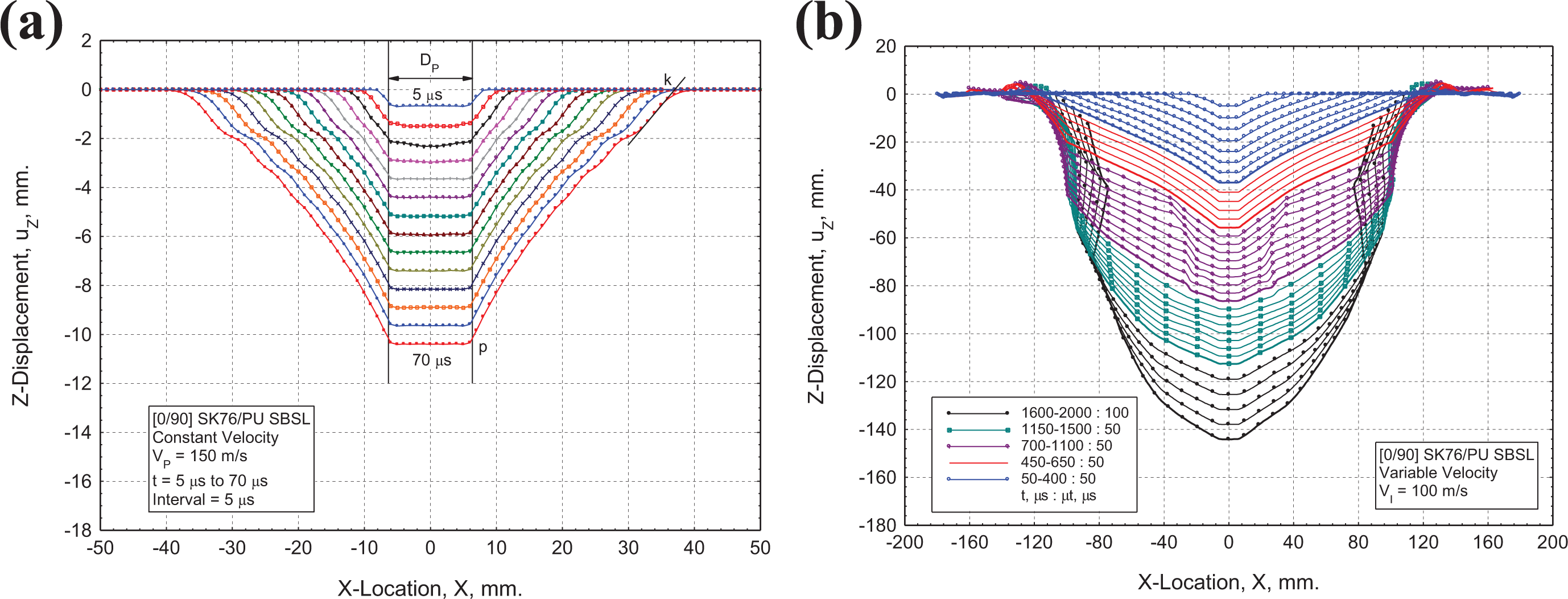
The 2D-Membrane theory applies to constant velocity impact on infinite isotropic membrane. In Haque et al.17 constant velocity ( 150 m/s) transverse impacts on an infinite 1D isotropic and 2D isotropic membrane have been conducted to validate the FE models with 1D fiber theory and 2D membrane theory as a first step. Then the validated model is used to study the transverse impact on an orthotropic [0/90] SK76/PU SBSL membrane where the formation of a diamond shaped transverse cone has been identified and the results of this analysis is reproduced in Figure 3(a) from Haque et al.17 Using Figure 3(a), the cone wave velocities () had been determined from the deformation profiles in the time range , which showed that for [0/90] SBSL starts at 1D value, 401 m/s, and increases over time up to 472 m/s at time . Ahead of the cone wave, an axial/implosion wave propagates with wave velocity 9782 m/s. For a finite size, 360 mm, single layer (1L) SBSL, the time for the axial/implosion wave to reflect back from the free edge to the projectile root is calculated to be (characteristic time). This implies that the implosion wave will reverberate between the edge and impact center of the 1L-SBSL once in every and will interact with the outward cone wave front. The net effect is essentially to slow down the cone wave front velocity.
Formation of deformation cone under transverse impact on a [0/90] SK76/PU SBSL. Plots of Z-displacement, uZ, along X-axis on Y = 0 plane, (a) Constant velocity transverse impact on [0/90] SK76/PU infinite SBSL, 150 m/s, Reproduced from Figure 4(a) Haque et al.17; (b) Variable velocity transverse impact on finite size [0/90] SK76/PU SBSL (performed under this study), 360 mm, , .
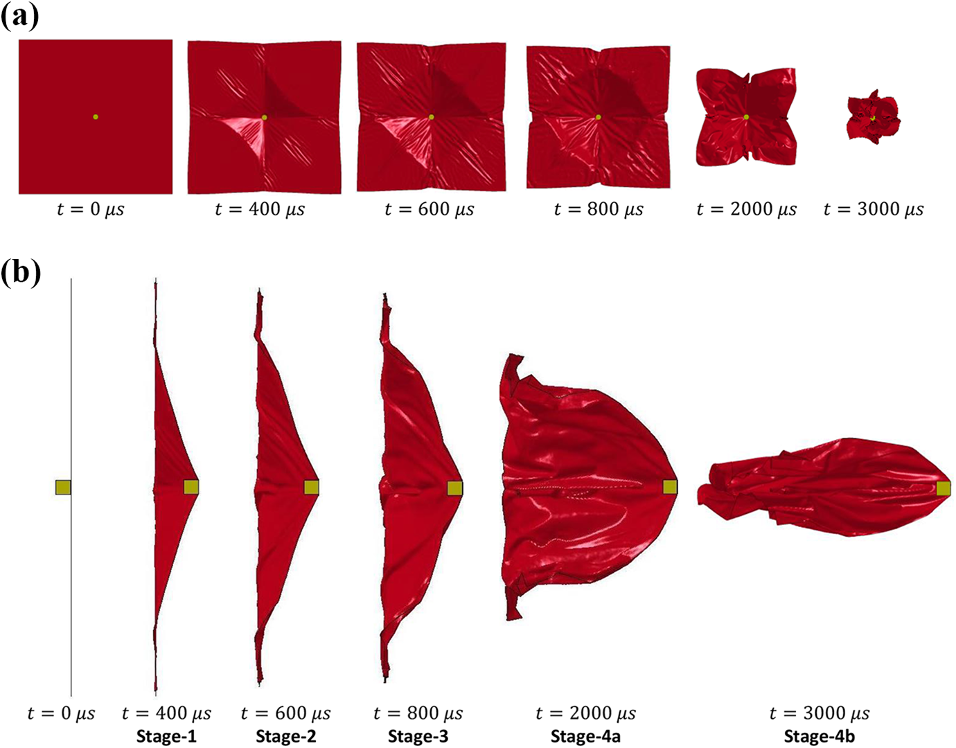
(a) Top view (XY-plane); and (b) Cross-sectional view (ZY-plane rotated by +90°) of the different stages of dynamic deformation of a single layer soft ballistic sub-laminate (1L-SBSL), 360 mm, , .
In this study, more realistic variable velocity impacts with initial impact velocity VI of a 12.7 mm RCC on the finite size 1L-SBSL ( 360 mm) is conducted for the range of impact velocities, i.e. 100 m/s 150 m/s. The first non-perforating impact simulation on 1L-SBSL with 100 m/s has been conducted for 4000 (4 ms) to study the large deformation behavior of the 1L-SBSL over a long period of time with many reverberations of the axial wave along the in-plane directions of the orthotropic membrane. Figure 3(b) shows the large deformation cone wave profiles similar to the infinite membrane up to time , followed by cone wave profiles up to time at an interval of which are interacting with the reverberating implosion wave. Top views and cross-sectional views of the large deformation behavior of 1L-SBSL have been presented in Figure 4 up to 3 ms. Four distinct stages of deformation have been observed (Figures 3(b) and 4) in four different time ranges; i.e. (i) Stage-1 (blue color profiles in Figure 3(b)) in the time range (), (ii) Stage-2 (orange color) in the time range, (), (iii) Stage-3 (violet color) in the time range, (),and (iv) Stage-4 (teal and black color) in the time range, ().
In Stage-1 (blue color profiles in Figure 3(b)), the growth of the deformation cone appears to be self-similar. In Stage-2 (orange color), the deformation cone shows self-similar growth with edge-pull which slows down the cone wave velocity to a near zero value. A double-V-hat deformation profile with three distinct zones (except the flat under the projectile) is observed at the end of this deformation stage (at time ). A secondary cone wave is observed in Stage-3 (violet color), however, the secondary cone wave soon disappears with continued large deformation of the SBSL and this is when the Stage-4 begins. A fully developed Stage-4a (teal and black color) and Stage-4b deformation profile at time can be seen in Figures 3(b) and 4. Figure 4 shows different stages of dynamic deformation of 1L-SBSL. From these figures, it is evident that the large deformation modes of finite size SBSLs identified in Haque et al.,17 i.e. (i) edge-pull, (ii) crease formation, (iii) folding, and (iv) dishing; are present for the 360 mm 1L-SBSL. Similar deformation patterns have been reported in Gilson et al. and Hazzard et al.7,10 in modeling transverse impact on hard ballistic soft laminates using solid elements.
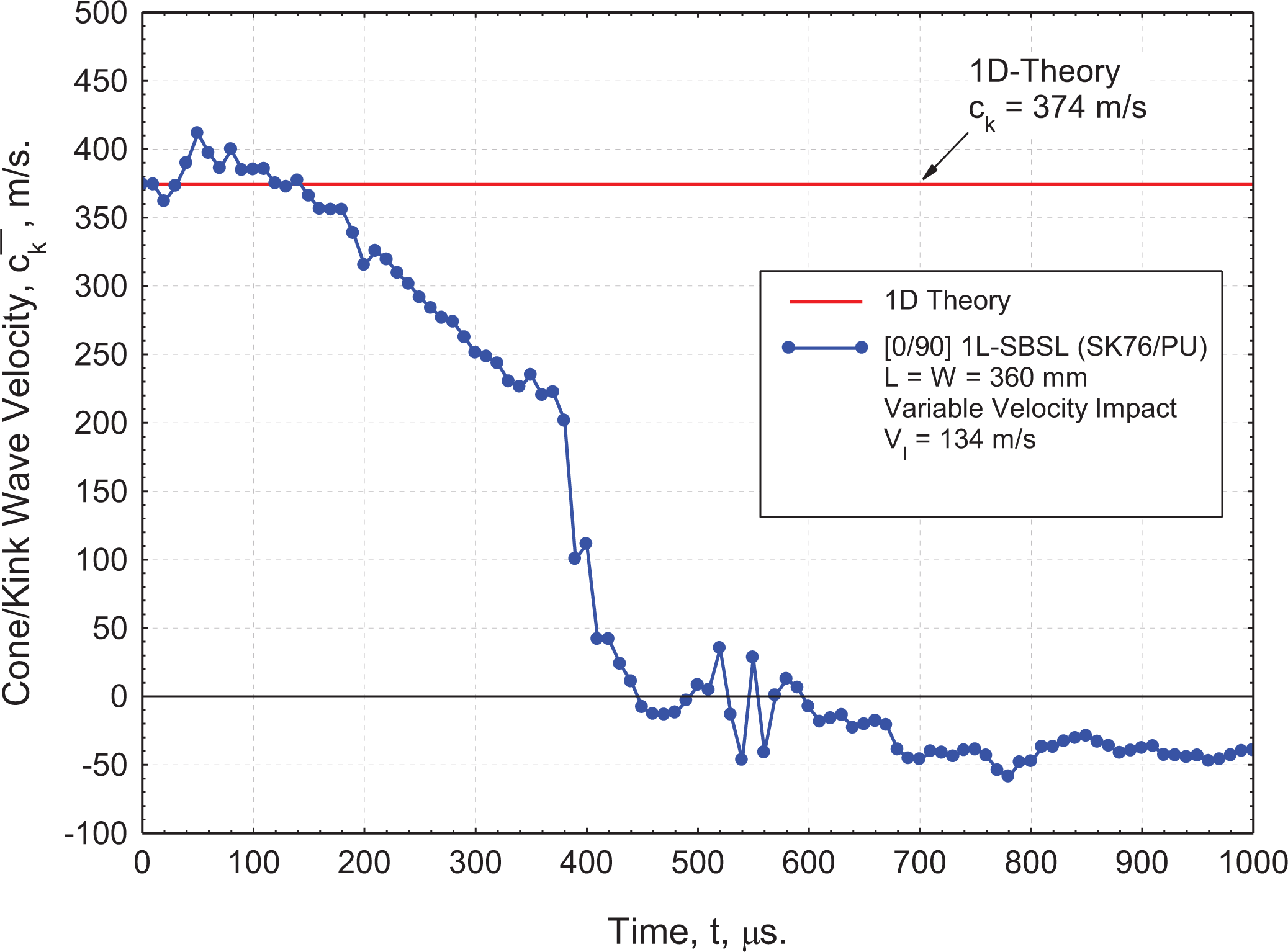
Another impact simulation at a near-perforation velocity 134 m/s is conducted to study the cone wave velocity of a finite size ( 360 mm) 1L-SBSL. The cone/kink wave velocity of a 360 mm square 1L-SBSL is found to start at the 1D value ( 374 m/s), rises above the 1D value till time , and then exponentially decreases to a near zero value at time , and even becomes negative after that (Figure 5). The near zero cone/wave velocity at time reveals the fact that the growth of the transverse cone virtually stops at this time. The negative cone wave velocity after time explains the reduction in radial dimensions of the 1L-SBSL as it deforms to a cone shape (Figure 4 in Stage-4a and Stage-4b) of large deformation. 1D cone wave velocity , which is a function of the implosion strain ; which is a function of constant impact velocity of the projectile VP.39 Impact energy transfer to the individual membrane/layer is a function of the cone wave speed , which is a function of VP. Near perforation velocity 134 m/s generate the highest cone wave speed of 374 m/s; however, any impact velocity less than 134 m/s will generate a lower cone wave velocity than 374 m/s. Since the energy transfer to the target membrane is a function of cone wave speed, the deformation dynamics is thus a function of impact velocity VI, which will be discussed later in Figure 6(a).
Cone/Kink wave velocity for a finite size [0/90] SK76®/PU SBSL under transverse impact. In-plane dimensions: , Characteristic time , Impact velocity .
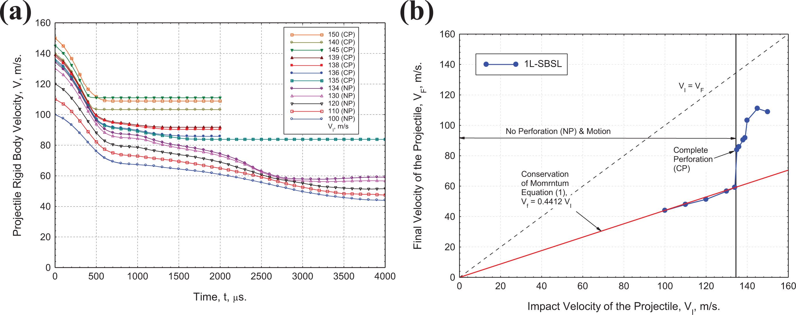
Perforation dynamics of a [0/90] SK76/PU 1L-SBSL, (a) Time history of projectile RBV, (b) Final velocity vs. impact velocity of the projectile. , . 15.9654 g, 12.6052 g, , and . 135 m/s.
In order to determine the perforation velocity of a finite size 1L-SBSL ( 350 mm), 12 impact simulations have been conducted in the impact velocity range 100 m/s 150 m/s. Time history of the projectile rigid body velocity (RBV) is presented in Figure 6(a) for different impact velocities. In non-perforating (NP) cases, the final velocity of projectile along with the entire 1L-SBSL becomes constant as presented in Figure 6(b) as “No Perforation (NP) and Motion.” In complete perforating (CP) cases with failure conditions along primary fiber directions ( 2880 MPa), the projectile perforates the 1L-SBSL and exits with a constant final velocity. Final velocity of the projectile of both non-perforating (NP) and complete perforating (CP) impact cases are presented in Figure 6(b) as a function of impact velocities. Maximum non-perforating impact velocity is found to be 134 m/s, and the minimum perforating impact velocity is found to be 135 m/s; which appears as a jump in final velocity of the projectile as shown in Figure 6(b). Since the cone wave speed is a function of impact velocity, the deformation dynamics of a single layer SBSL is also a function of impact velocity; which is evident by comparing the curvature of the time history of the projectile rigid body velocity at near perforation impact velocity 134 m/s and at a lower impact velocity at 100 m/s in the time range 2000 3500 .
At impact velocities lower than the minimum perforation velocity, the projectile-target pair shall move together (Figure 4) with a constant final velocity, , which can be determined from the conservation of momentum as follows:
where, , and . For the 1L-SBSL of dimension ; 1.267 and 0.4412. Final velocities for non-perforating (NP) projectiles (Figure 6(b)) match well with the conservation of momentum prediction defined by equation (1). At the minimum perforation velocity and higher velocities, equation (1) is not applicable due to the fact that the target and the projectile are moving at different velocities.
A soft-ballistic armor pack (SBAP) is made from multiple layers of [0/90] soft-ballistic sub-laminates (SBSL). In this section, finite element model for eight different finite size ( 360 mm) SBAPs, i.e. (i) 2L-SBAP, (ii) 3L-SBAP, (iii) 4L-SBAP, (iv) 8L-SBAP, (v) 16L-SBAP, (vi) 24L-SBAP, and (vii) 32L-SBAP have been developed with the geometry, gap, mesh size, mass, contact, friction, hourglass, material properties, and boundary conditions defined in the FE modeling section and in Tables 1 and 2. Variable velocity impacts over a range of impact velocities have been simulated in determining the “Minimum Perforation Velocity ” as described in the case of the 1L-SBSL.
Perforation and deformation dynamics of 2L-SBAP, and 3L-SBAPare presented in Appendix A, while the same for the 4L-SBAP, 8L-SBAP, 16L-SBAP, 24L-SBAP, and 32L-SBAP are presented in this section.
Perforation and deformation dynamics of 4L-SBAP
A total of 14 impact simulations have been conducted for the 4L-SBAP in the range 150 m/s 275 m/s. Figure 7(a) shows the time history of the projectile rigid body velocity, where the no perforation (NP) and motion of the projectile target pair is found in the impact velocity range 150 m/s 235 m/s, for which the simulations have been conducted for 5 ms. Figure 7(b) shows the final velocity VF as a function of impact velocity VI. The final velocity of NP cases matches well with the momentum equation (1). Partial penetration (PP) and motion is observed in the range 235 m/s 245 m/s. Complete perforation (CP) is observed for impact velocities 246 m/s. Thus the minimum perforating velocity is found to be 246 m/s.
Perforation dynamics of a [0/90] SK76/PU 4L-SBAP. (a) Projectile RBV vs. time; (b) Final velocity vs. impact velocity of the projectile. , . . . and . 246 m/s.
Dynamic deformation of the 4L-SBAP is presented in Figure 8 as a function of impact velocity of the projectile. Non-perforating (NP) impacts show Stage-4 (Figure 4(b)) type of deformation shapes (Figure 8(a) and (b) for 200 m/s and 235 m/s, respectively). Partial perforation (PP) impact show dish type (Stage-4a, Figure 4(b)) of deformation shapes (Figure 8(c) and (d) for 240 m/s and 245 m/s), while the complete perforation (CP) impacts show Stage-3 (Figure 4(b)) type of deformation shapes (Figure 8(e) and (f) for 246 m/s and 250 m/s). It is interesting to note that at 245 m/s two (2) out of four (4) layers of the 4L-SBAP have been perforated (Figure 8(d)), while all the four (4) layers have been perforated at 246 m/s (Figure 8(e)) which is a very narrow difference. The final velocity (VF) of partial perforation (PP) at 245 m/s and complete perforation (CP) at 246 m/s appears as a jump in Figure 7(b) signifying the minimum perforation velocity.
Dynamic deformation and perforation of a 4L soft ballistic armor pack (4L-SBAP), X-Sectional Views (ZY-plane rotated by +90°). (a) VI = 200 m/s, t = 5000 µs, NP, similar to Stage-4b; (b) VI = 235 m/s, t = 1000 µs, NP, similar to Stage-4a; (c) VI = 240 m/s, t = 1000 µs, PP-1L; (d) VI = 245 m/s, t = 800 µs, PP-2L; (e) VI = 246 m/s, t = 500 µs, CP-4L; (f) VI = 250 m/s, t = 400 µs, CP-4L.
Perforation and deformation dynamics of 8L-SBAP
For the 8L-SBAP, 27 impact cases have been simulated in the impact velocity range 25 m/s 400 m/s. Figure 9(a) shows the rigid body velocity (RBV) of the projectile, and Figure 9(b) shows the final velocity (VF) of the projectile as a function of impact velocity (VI). No perforation (NP) is observed in the impact velocity range 0 m/s 285 m/s marked as “NP and Motion” in Figure 9(b), where equation (1) can be used in predicting the final velocity of the projectile-target pair moving together, which appears as a constant final velocity with time (Figure 9(a)). Perforation of the first (1st) layer is observed at followed by complete perforation (CP) of all eight layers at . While partial perforation (PP) occurs in the impact velocity range 288 m/s 304 m/s, it is not immediately obvious from Figure 9(a). However, partial perforation (PP) marked as “PP and Motion” in Figure 9(b) is clearly distinguishable as a non-linear deviation from the momentum conversation given in equation (1). On the other hand, complete perforation (CP) at 305 m/s appears as a jump in final or residual velocity in both the Figure 9(a) and (b). The minimum perforation velocity for the 8L-SBAP of in-plane dimension with is found to be 305 m/s.
Perforation dynamics of a [0/90] SK76/PU 8L-SBAP. (a) Projectile RBV vs. time; (b) Final velocity vs. impact velocity of the projectile. , . . . and . 305 m/s.
Perforation resistance forces for non-perforating (NP) and completely perforating (CP) impacts on 8L-SBAP are presented in Figure 10(a). Note that the momentum transfer ( to the target 8L-SBAP for non-perforating impact at 300 m/s is higher than the perforating impact at 350 m/s. Time history of perforation resistance force and projectile rigid body velocity (RBV) for CP impact at 350 m/s are presented in Figure 10(b). RBV of the projectile at 50 interval (RBV-Interval in Figure 10(b) has been extracted to calculate the average forces (Avg. Force in Figure 10(b), ) and energy transfer to the target () over these intervals. Impact energy transfer to the target is calculated to be 55% at time t = 100 , 77% at time t = 200 , 82% at time t = 250 . Impact energy transfer to the target for NP impact case at 285 m/s (not shown in figure) is calculated to be 55% at time t = 100 , 85% at time t = 200 , 96% at time t = 300 . For the 8L-SBSL, the momentum and energy transfer process to the target is almost complete by time time t = 300 , however, the deformation of SBAP continues and is presented next.
Perforation resistance force of the 8L-SBAP. (a) Force vs. time under non-perforating and perforating impacts; (b) Force and velocity vs. time for complete perforation at 305 m/s. In-plane Dimensions , Characteristic time .
Deformation dynamics of the 8L-SBAP for a non-perforating (NP) impact at 285 m/s is presented in Figure 11. It is interesting to note that until time , 85% of the impact energy is transferred to the SBAP target, and the transverse cone has diamond shape in the basal plane and a conical shape in cross-sectional plane mimicking Stage-1 of 1L-SBSL deformation. While edge-pull, crease-formation, and folding are the dominant deformation mechanisms, it is interesting to note that all 8-layers are deforming together, as if they are one thick layer. At time , 98% of the impact energy is transferred to the SBAP target, and the cone wave growth is almost complete, and the growth virtually stops at around . Significant edge-pull occurs between and , the deformation shape transitions from a cone shape to a dish shape, while the basal shape transitions from a diamond shape to a octagon shape, and exfoliation of the edges continue to grow. Finally, the entire 8L-SBAP starts moving at a constant velocity from and beyond.
Dynamic deformation of an 8L soft ballistic armor pack (8L-SBAP) under non-perforating Impact. (a) Top View (XY-Plane), (b) Cross-sectional view (ZY-plane rotated by +90°). Impact velocity, . In-plane dimensions: , Characteristic time .
In case of complete perforation (CP) at impact velocity 305 m/s, the four (4) top layers of the 8L-SBAP is perforated by time t = 200 (77% impact energy transferred). Complete perforation (CP) of all 8 layers occurs around time t = 300 (82% impact energy transferred) which can be seen in Figure 12 (at time t = 400 ). The 8L-SBSL continues to shrink in in-plane dimensions (XY-Plane) after complete perforation at time t = 300 and exfoliate through the thickness (Figure 12). All stages of deformation for a single layer SBSL are present in the 8L-SBAP during complete perforation, however, are qualitatively different than non-perforating 8L-SBAP because of the instabilities arising from the perforation site.
Dynamic deformation of an 8 layer soft ballistic armor pack (8L-SBAP) under perforating impact. (a) Top view (XY-Plane), (b) Cross-sectional view (ZY-plane rotated by +90°). Impact velocity, . In-plane dimensions: , Characteristic time .
Perforation mechanics of 16L-SBAP and 24L-SBAP
Perforation mechanics of 16L-SBSL and 24L-SBSL are presented in this section using the time history of projectile rigid body velocity, while the deformation dynamics is omitted for brevity. However, deformation dynamics of 32L-SBAP will be presented in the next section. For the 16L-SBAP, 23 impact cases have been simulated in the impact velocity range 125 m/s 425 m/s. Figure 13(a) shows the rigid body velocity (RBV) of the projectile, and Figure 13(b) shows the final velocity (VF) of the projectile as a function of impact velocity (VI). No perforation and rebound of the projectile (negative final velocity of the projectile) have been observed in the impact velocity range 125 m/s 250 m/s. Partial perforation and forward motion of the projectile-target pair have been observed in the impact velocity range 275 m/s 369 m/s. Complete perforation is observed at 370 m/s, i.e. 370 m/s.
Perforation dynamics of a [0/90] SK76/PU 16L-SBAP. (a) Projectile RBV vs. time, (b) Final velocity vs. impact velocity of the projectile. , . , , , and . 305 m/s.
For the 24L-SBAP, 14 impact cases have been simulated in the impact velocity range 275 m/s 440 m/s. Figure 14(a) shows the rigid body velocity (RBV) of the projectile, and Figure 14(b) shows the final velocity (VF) of the projectile as a function of impact velocity (VI). Partial perforation and rebound of the projectile have been observed in the impact velocity range 275 m/s 350 m/s. Partial perforation and forward motion of the projectile-target pair have been observed in the impact velocity range 360 m/s 420 m/s. Complete perforation is observed at 440 m/s. In absence of impact data between 420 m/s and 440 m/s, and considering the jump in the final velocity from 64 m/s to 192 m/s, the minimum perforation velocity for 24L-SBSL is taken to be 440 m/s.
Perforation dynamics of a [0/90] SK76/PU 24L-SBAP. (a) Projectile RBV vs. time, (b) Final velocity vs. impact velocity of the projectile. , . , , , and . 440 m/s.
Perforation and deformation dynamics of 32L-SBAP
For the 32L-SBAP, 11 impact cases have been simulated in the impact velocity range 300 m/s 500 m/s. Figure 15(a) shows the rigid body velocity (RBV) of the projectile, and Figure 15(b) shows the final velocity (VF) of the projectile as a function of impact velocity (VI). Partial perforation and rebound of the projectile have been observed in the impact velocity range 300 m/s 400 m/s. Partial perforation and forward motion of the projectile-target pair have been observed in the impact velocity range 425 m/s 485 m/s. Complete perforation is observed at 500 m/s. In absence of impact data between 485 m/s and 500 m/s, and considering the jump in the final velocity from 69 m/s to 190 m/s, the minimum perforation velocity for 32L-SBSL is taken to be 500 m/s.
Perforation dynamics of a [0/90] SK76/PU 32L-SBAP. (a) Projectile RBV vs. time, (b) Final velocity vs. impact velocity of the projectile. , . , , , and . 500 m/s.
Perforation resistance force as a function of time for the 32L-SBAP is presented in Figure 16(a) for 11 impact cases studied. Upon impact, the resistance force obtains its first peak within 7 to 9 followed by a second peak within 25 to 33 . A drop in resistance force to a near constant value is observed in the time range 50 to 60 when the axial wave reflects back from the edge of the 32L-SBAP and arrives at the projectile root (). In order to understand the energy transfer to the target as a function of time, the resistance force and projectile rigid body velocity of the projectile are presented in Figure 16(b) for the near perforating impact case with 475 m/s. The energy transfer to the target 32L-SBAP has been calculated at 50 interval revealing that 68% impact energy is transferred by time t = 50 , 83% by time t = 100 , and 94% by time t = 200 . The 50 time interval has also been used to calculate the average resistance force over the time interval as shown in Figure 16(b) which helps understanding the role of resistance force at 50 time interval on the deformation dynamics of the 32L-SBAP and is presented next.
Perforation resistance force of the 32L-SBAP. (a) Force vs. time under non-perforating and perforating impacts; (b) Force and velocity vs. time for near complete perforation at 475 m/s. In-plane dimensions , Characteristic time .
In case of partial-perforating impact at 300 m/s, Figure 17 shows that 96% energy has been transferred to the target at time t = 100 while the deformation cone has developed about three projectile diameters where the transferred energy is stored as the elastic energy of the deformation cone. The 1st layer of the 32L-SBAP has been perforated by time t = 100 and the 2nd layer by time t = 200 (where 99% energy is transferred and projectile velocity is 33 m/s). At time t = 300 100% of the impact energy is transferred and projectile stops and starts rebounding with final rebound velocity of 13 m/s at time t = 600 . The dynamic deformation of the 32L-SBAP in the time range 300 600 is a case of redistribution of transferred momentum and energy within the 32L-SBAP since the projectile loses contact with the SBAP at time t = 300 .
Dynamic deformation of the 32L-SBAP under partial-perforating impact velocity, 300 m/s (No. of layers perforated at 100 NoLP = 1, at 200 and beyond NoLP = 2). Cross-sectional view (ZY-plane rotated by +90°). In-plane dimensions: 360 mm, Characteristic time .
Dynamic deformation of the 32L-SBAP at a near perforating impact case of 475 m/s is presented in Figure 18. At time t = 100 , 68% impact energy is transferred to the target while the number of layers perforated is NoLP = 17. The energy transfer and number of layers perforated at time t = 200 and 300 are 90% and 97% and NoLP = 23 and 27; respectively. No significant energy transfer or perforation of additional layers have been observed beyond t = 300 . It is important to note that since the perforation of individual layers is modeled by eroding elements exceeding the tensile strength under membrane tension, the failed layers immediately retracts back as there remains stored elastic energy in the deformed membrane. The energetic retraction of failed layers occurs as soon as a layer is failed along with the redistribution of transferred momentum which can be seen for all time ranges presented in Figure 18. Further discussion of multi-layer SBSLs are presented next.
Dynamic deformation of the 32L-SBAP under near-perforating impact velocity, 475 m/s (No. of layers perforated at 100 NoLP = 17, at 200 NoLP = 23, at 300 and beyond NoLP = 27). Cross-sectional view (ZY-plane rotated by +90°). In-plane dimensions: 360 mm, Characteristic time .
Perforation mechanics of multi-layer SBAP
Perforation mechanics for 1L, 2L, 3L, 4L, 8L, 16L, 24L, and 32L-SBAP under variable velocity transverse impact of a 12.7 mm RCC projectile have been presented in the previous sections. A comparative study of the final velocity of the projectile (VF) as a function of impact velocity (VI) for 1L to 32L-SBAP is presented in Figure 19(a). For all nL-SBAPs (n = 1, 2, 3, 4, 8, 16, 24, 32), a jump in the plot has been identified as the complete perforation of the SBAPs. Five different perforation mechanisms have been identified and is presented in both Figure 19(a) and Table 3; i.e. (i) No Perforation and Motion (NP&M), (ii) No Perforation and Rebound (NP&R), (iii) Partial Perforation and Rebound (PP&R), (iv) Partial Perforation and Motion (PP&M), and (v) Complete Perforation (CP).
Summary of Perforation Mechanics of nL-SBAPs, 1, 2, 4, 8, 16, 24, 32. (a) Final velocity of the projectile VF as a function of impact velocity, VI. (b) Minimum perforation velocity as a function of areal density of the nL-SBAPs.
Perforation mechanisms for multi-layer nL-SBAP ( 1, 2, 3, 4, 8, 16, 24, 32) and perforation grouping of SBAPs as a function of perforation mechanisms.
Perforation group
#L-SBAP
Perforation velocity limits in m/s
.LE.a
.GE.b
(i) NPc and Motion
(ii) NPc and Rebound
(iii) PPd and Rebound
(iv) PPd and Motion
(v) CPe and
PG-1
1L
134
—
—
—
135
PG-2
2L
185
—
—
190
192
3L
210
—
—
212
213
4L
235
—
—
245
246
8L
285
—
—
304
305
PG-3
16L
—
250
—
369
370
PG-4
24L
—
—
350
420
440
32L
—
—
400
485
500
a LE.—less than or equal to, bGE.—greater than or equal to, cNP—no perforation, dPP—partial perforation, eCP—complete perforation.
Based on the different perforation mechanisms in a SBAP, the multi-layer nL-SBAPs are grouped in four different groups as shown in Table 3 and the perforation groups (PG) are: (a) PG-1 [1L], where “(i) NP and Motion” and “(v) CP” mechanisms are present; (b) PG-2 [2L, 3L, 4L and 8L], where “(i) NP and Motion,” “(iv) PP and Motion,” and “(v) CP” mechanisms are present; (c) PG-3 [16L], where “(ii) NP and Rebound,” “(iv) PP and Motion,” and “(v) CP” mechanisms are present; and (d) PG-4 [24L and 32L], where “(iii) PP and Rebound,” “(iv) PP and Motion,” and “(v) CP” mechanisms are present. Table 3 also shows the upper limit [.LE.] of perforation mechanism velocities for mechanisms (i) to (iv); and the lower limit [.GE.] of the perforation mechanism (v), i.e. the minimum velocity of perforation . A jump in final velocity of the projectile identifies the minimum perforation velocity, , which is presented in Figure 19(b) as a function of areal density of the nL-SBAP, . For multi-layer SBAPs (8L, 16, 24L, and 32L), the minimum perforation velocity is linear with the areal density of the SBAP targets (Figure 19(b)). For the 1L, 2L, 3L, 4L, up to 8L SBAPs; the minimum perforation velocities appears to be non-linear and this non-linearity is attributed to the perforation mechanisms of the perforation groups PG-1 and PG-2.
Total momentum transferred , and the total energy transferred to the target SBSL and SBAPs have been presented in Figure 20. Except the 1L-SBSL, 2L-SBAP, 3L-SBAP, 4L-SBSL, and 8L-SBAP; the transferred momentum pT is equal to the initial momentum for all non-perforating impacts, shows a non-linear drop for partial perforations, and a sharp drop for complete perforations at (Figure 20(a)). On the other hand, the energy transferred to the target SBSL and SBAPs ET is equal to the impact energies for the non-perforating and partial perforation cases, however, shows a sharp drop for perforating impact cases (Figure 20(b)).
Momentum and Energy transfer to the target SBSL and SBAPs. (a) Transferred momentum , and (b) Transferred energy .
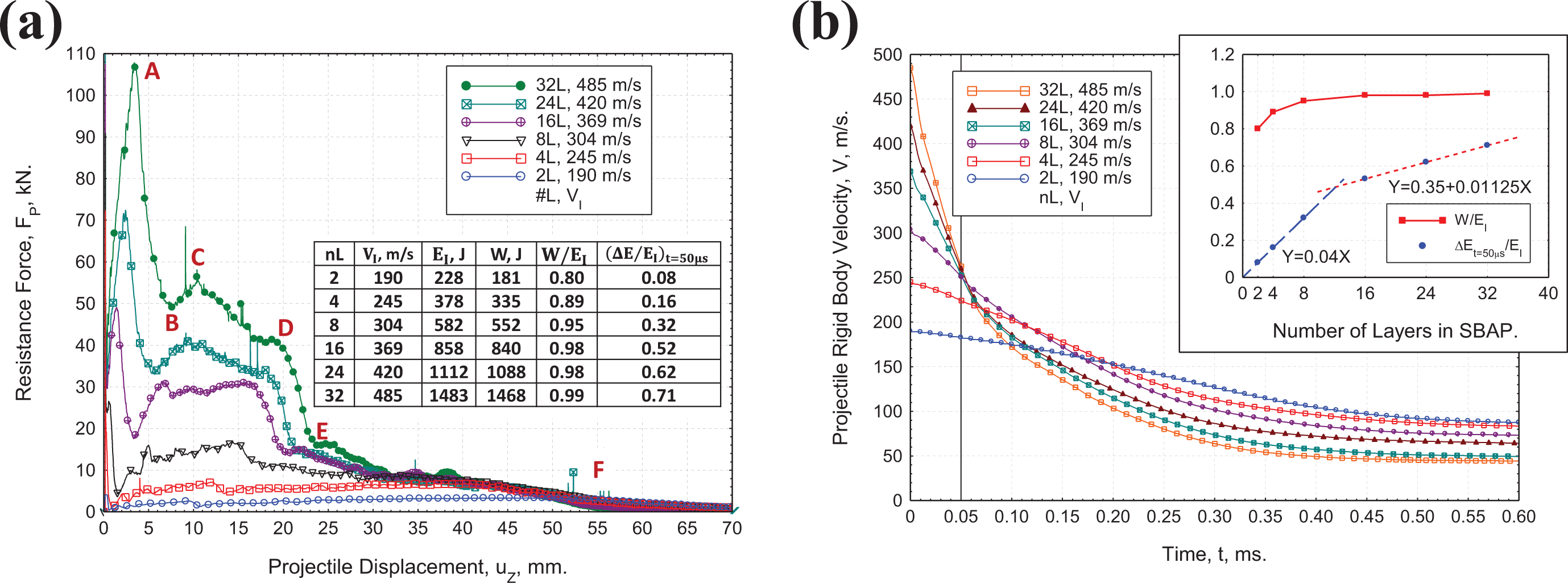
Table 3 shows the minimum velocity for complete perforation and motion as “CP and Motion,” and the maximum velocity for partial perforation and motion as “PP and Motion.” The difference between the minimum “CP and Motion” velocity and maximum “PP and Motion” velocity is 1 m/s for 1, 2, 3, 4, 8, and 16; 10 m/s for 24, and 15 m/s for 32. Thus, if we want to know the overall dynamic deformation mechanisms at the onset of complete perforation, we shall look at the perforation cases at the maximum “PP and Motion” impact velocities. In Figure 21, cross-sections of the multi-layer nL-SBAPs ( 2, 4, 8, 16, 24, 32) have been presented at their respective maximum “PP and Motion” impact velocities. Resistance forces for the nL-SBAPs ( 2, 4, 8, 16, 24, 32) have been presented in Figure 22(a) as a function of projectile displacements at their respective maximum “PP and Motion” impact velocities. Mechanics of 1L-SBAP has been presented in Haque et al.,17 and thus omitted from Figures 21 and 22(a). Clearly, the deformation mechanisms and shapes for 2, 3, 4, 8 if different than the 16, 24, 32. While SBAPs with 2, 3, 4, 8 shows exfoliation of individual layers, the SBAPs with 16, 24, 32 shows that the rear face layers are sticking close to each other because the momentum and energy transfer mechanisms to the SBAPs is different. Figure 22(a) shows that the ratio of work done and impact energy for SBAPs with 16, 24, 32 is constant, i.e. 0.98, while the same for 2, 3, 4, 8 is in the range 0.80 0.95. The ratio for nL-SBAP can be used to classify relatively thinner SBAPs ( 2, 3, 4, 8) and relatively thicker SBAPs ( 16, 24, 32).
Dynamic deformation of multi-layer nL-SBAPs ( 2, 4, 8, 16, 24, 32) at the maximum “PP and Motion” impact velocities. (a) 2L, 190 m/s, (b) 4L, 245 m/s, (c) 8L, 304 m/s, (d) 16L, 369 m/s, (e) 24L, 420 m/s, (f) 32L, 485 m/s. RCC Projectile, .
Comparison of (a) Force-Displacement and (b) Time history of projectile rigid body velocity of Multi-Layer nL-SBAPs ( 2, 4, 8, 16, 24, 32) impacted at their maximum “PP and Motion” impact velocities. RCC Projectile, . Work done , and impact energy . .
Resistance force vs displacement for 16L, 24L, and 32L SBAPs in Figure 22(a) shows non-linear rise in force as a function of displacement to a peak value (32L, Point A, 3.4 mm) followed by a sharp drop signifying perforation of the first few layers of the nL-SBAP (Figure 18, 32L, 485 m/s, 100 s). Load rises from the first valley (Point B, 7.6 mm) to the second peak (Point C, 10.4 mm) and then undergo a progressive decrease signifying large deformation of the remaining layers (Figure 18, 200 s, Point D, 20.0 mm). A second load drop signifies perforation of additional layers (Figure 18, 300 s, Point E, 24.0 mm) leading to a constant final velocity (Figure 18, 400∼600 s, Point F, 55.0 mm; Figure 22(b), time 0.40∼0.60 ms). Force-displacement of the 8L-SBAP has some similarity, however, the same for 2L- and 4L-SBAP is significantly different as their peak force occur at a larger displacement ( 40 mm for 4L, 50 mm for 2L). Time history of the projectile rigid body displacement for the impact cases presented in Figure 22(a). These maximum “PP and Motion” impact velocities shows exponential decay to the final velocity VF. At , fraction of total energy transfer to the target can be expressed as , which is shown in Figure 22. Fractional energy transfer for the 2, 4, 8 SBAPs is linear with n with a slope of 0.04, and the same for the 16, 24, 32 SBAPs is linear with n with a different slope of 0.01125; which differentiates the two group of SBAPs as “thin” and “thick.” Figures 19 to 22 and Table 3 summarizes the overall impact performance of multi-layer nL-SBAP system ( 1, 2, 3, 4, 8, 16, 24, 32). Practical applications of SBAPs may require a total number of SBSLs more than 40, however, present analysis provides the fundamental understanding of the impact dynamics of multi-layer SBAPs.
The FE models of multi-layer nL-SBAPs and analysis methodology developed in this study can be further used to study the perforation behavior other soft-ballistic materials such as, polymer films, Kevlar™ fabrics, Gold-Shields, Spectra™ SBSL and fabrics, Dyneema® fabrics and other SBSL variants, etc. The dynamic deformation and perforation mechanism are strong functions of axial wave speed (), cone wave velocity (), and maximum tensile strength () along the fiber direction. Parametric simulations varying these three properties can be performed to evaluate the free-standing perforation velocities of any SBSL materials listed above.
The present study of transverse impact on multi-layer SBAPs with free standing boundary conditions provided the detail deformation and perforation mechanism, however, the real “Soft Armor” application is intended to be used with the support condition of the human thorax while the ballistic resistance of the soft armor system (with wearable jacket) is evaluated using surrogate support such as artists modeling clay or synthetic polymer composite as backing materials [https://www.nist.gov/news-events/news/2019/03/assessing-next-generation-backing-materials-body-armor-testing]. Interaction between the backing clay and the SBAP adds complexity to the present model and is an important topic for future research.
Conclusions
The following conclusions have been made from the present computational simulations of [0/90] UHMWPE soft-ballistic sub-laminate (SBSL) and multi-layer soft-ballistic armor packs (SBAP).
Deformation dynamics of a finite size single layer [0/90] SBSL under non-perforating impact shows diamond shaped cone wave formation, slowing down of cone wave velocity, and even negative cone wave velocity yielding four (4) different stages of deformation.
A minimum perforation velocity, , for a finite size single layer [0/90] SBSL has been defined as the minimum impact velocity required to perforate a finite size 1L-SBSL.
Impacts on multi-layer SBAPs show that the complete perforation of nL-SBAPs ( 2, 3, 4, 8, 16, 24, 32) occurs under progressive partial perforation of individual SBSL layers in a nL-SBAP from the impact side toward the rear side of the SBAPs.
Impact momentum is transferred to the deformation cone of the target. As the cone wave velocity increases with impact speed, momentum transfer and redistribution mechanisms for multi-layer nL-SBAPs changes with the increase in number of layers.
For SBAP areal density 1 kg/m2, i.e. for 1L-, 2L-, 3L-, 4L-, and 8L-SBAPs; “NP and Motion” and “PP and Motion” perforation mechanisms have been observed prior to complete perforation “CP.” In case of “NP and Motion,” the final velocity of the projectile target pair can be calculated using the momentum equation. Considering the similarities in perforation dynamics of 2L to 8L SBAPs, they are grouped together as “Perforation Group 2 (PG-2).” The minimum perforation velocities of 1L to 8L SBAPs; and the ratio of work done to the impact energy are non-linear with the areal-densities of the target.
For SBAP areal density 1 kg/m2, i.e. for 16L-, 24L-, and 32L-SBAPs; “NP and Rebound,” “PP and Rebound,” and “PP and Motion” perforation mechanisms have been observed prior to complete perforation “CP.” Considering the similarities in perforation dynamics of 24L and 32L SBAPs, they are grouped together as “Perforation Group 4 (PG-4).” The minimum perforation velocities of 8L to 32L SBAPs are found to be linear with the areal-densities of the target; and the ratio of work done to the impact energy is approximately equal to 1.
At near perforation velocities, perforation dynamics of the 16L, 24L, and 32L SBAPs occurs in three phases, i.e. (i) perforation of few layers in the time range 50 100 , (ii) growth of deformation cone and progressive perforation in the time range 100 200 , and (iii) progressive perforation of the additional layers in the time range 200 300 leading to the rigid body final velocity of the non-perforating layers and the projectile pair at time 300 .
A systematic finite element analysis of the perforation dynamics of SBSL and SBAPs have been presented for the first time in this paper.
Footnotes
Acknowledgments
The authors gratefully acknowledge Molla A. Ali’s contribution in organizing the cited literature by year and by topic; and Zannatul Mawa’s contribution in processing the 2L-SBAP, and 3L-SBAP computational data.
Declaration of conflicting interests
The author(s) declared no potential conflicts of interest with respect to the research, authorship, and/or publication of this article.
Funding
The author(s) disclosed receipt of the following financial support for the research, authorship, and/or publication of this article: Research was sponsored by the Army Research Laboratory and was accomplished under Cooperative Agreement Number W911NF-12-2-0022 and W911NF-13-2-0027. The views and conclusions contained in this document are those of the authors and should not be interpreted as representing the official policies, either expressed or implied, of the Army Research Laboratory or the U.S. Government. The U.S. Government is authorized to reproduce and distribute reprints for Government purposes notwithstanding any copyright notation herein.
ORCID iD
Bazle Z (Gama) Haque
References
1.
CrouchI. Body armour—new materials, new systems. Def Technol2019; 15(3): 241–253.
2.
NayakRCrouchIKanesalingamS, et al.Body armor for stab and spike protection, Part 1: scientific literature review. Text Res J2018; 88(7): 812–832.
KhodadadiALiaghatGVahidS, et al.Ballistic performance of Kevlar fabric impregnated with nanosilica/PEG shear thickening fluid. Compos B Eng2019; 162: 643–652.
5.
MawkhliengUMajumdarA. Soft body armour. Text Prog2019; 51(2): 139–224.
6.
MawkhliengUMajumdarALahaA. A review of fibrous materials for soft body armour applications. RSC Adv2019; 10(2): 1066–1086.
7.
GilsonLImadARabetL, et al.On analysis of deformation and damage mechanisms of DYNEEMA composite under ballistic impact. Compos Struct2020; 253: 112791.
8.
HazzardMKCurtisPTIannucciL, et al.An investigation of in-plane performance of ultrahigh molecular weight polyethylene composites. In: ICCM International Conferences on Composite Materials, Copenhagen, Denmark, 2015, vol. 2015-July.
9.
HazzardMKHallettSCurtisPT, et al.Effect of fibre orientation on the low velocity impact response of thin Dyneema® composite laminates. Int J Impact Eng2017; 100: 35–45.
10.
HazzardMKTraskRSHeissererU, et al.Finite element modelling of Dyneema® composites: from quasi-static rates to ballistic impact. Compos A Appl Sci Manuf2018; 115: 31–45.
11.
ShenZHuDYangG, et al.Ballistic reliability study on SiC/UHMWPE composite armor against armor-piercing bullet. Compos Struct2019; 213: 209–219.
12.
YangYChenX. Investigation of failure modes and influence on ballistic performance of Ultra-High Molecular Weight Polyethylene (UHMWPE) uni-directional laminate for hybrid design. Compos Struct2017; 174: 233–243.
13.
KhodadadiALiaghatGTaherzadeh-fardA, et al.Impact characteristics of soft composites using shear thickening fluid and natural rubber–a review of current status. Compos Struct2021; 271: 114092.
14.
AroraSMajumdarAButolaBS. Structure induced effectiveness of shear thickening fluid for modulating impact resistance of UHMWPE fabrics. Compos Struct2019; 210: 41–48.
15.
NilakantanGNuttS. Effects of ply orientation and material on the ballistic impact behavior of multilayer plain-weave aramid fabric targets. Def Technol2018; 14(3): 165–178.
16.
NilakantanGHornerSHallsV, et al.Virtual ballistic impact testing of Kevlar soft armor: predictive and validated finite element modeling of the V0-V100 probabilistic penetration response. Def Technol2018; 14(3): 213–225.
KhodadadiALiaghatGBahramianAR, et al.High velocity impact behavior of Kevlar/rubber and Kevlar/epoxy composites: a comparative study. Compos Struct2019; 216: 159–167.
19.
YangYChenX. Determination of materials for hybrid design of 3D soft body armour panels. Appl Compos Mater2018; 25(4): 861–875.
20.
HaqueBZG. Modeling constant velocity transverse impact on Uhmwpe soft ballistic sub-laminate. In: CD Proceedings, SAMPE Balt, Baltimore, MD, May, 2015.
21.
(Gama) HaqueBZKearneyMMGillespieJW. Advances in protective personnel and vehicle armors. Recent Patents Mater Sci2012; 5(2): 105–136.
22.
(Gama) HaqueBZGillespieJW. Depth of penetration of Dyneema® HB26 hard ballistic laminates. J Thermoplast Compos Mater2021: 089270572110185. In Press.
23.
GamaBAGillespieJW. Finite element modeling of impact, damage evolution and penetration of thick-section composites. Int J Impact Eng2011; 38(4): 181–197.
24.
YangYChenX. Investigation of energy absorption mechanisms in a soft armor panel under ballistic impact. Text Res J2017; 87(20): 2475–2486.
25.
AroraSGhoshA. Evolution of soft body armor. 2018. Advanced Textile Engineering Materials, Chapter 13, pp. 499–552. Wiley Online Library. 10.1002/9781119488101.ch13.
26.
YangECLinforthSNgoT, et al.Hybrid-mesh modelling & validation of woven fabric subjected to medium velocity impact. Int J Mech Sci2018; 144: 427–437.
27.
NguyenLHLässigTRRyanS, et al.A methodology for hydrocode analysis of ultra-high molecular weight polyethylene composite under ballistic impact. Compos A Appl Sci Manuf2016; 84: 224–235.
28.
LässigTBagusatFPfändlerS, et al.Investigations on the spall and delamination behavior of UHMWPE composites. Compos Struct2017; 182: 590–597.
29.
LässigTRMayMHeissererU, et al.Effect of consolidation pressure on the impact behavior of UHMWPE composites. Compos B Eng2018; 147: 47–55.
30.
LässigTBagusatFMayM, et al.Analysis of the shock response of UHMWPE composites using the inverse planar plate impact test and the shock reverberation technique. Int J Impact Eng2015; 86: 240–248.
31.
Van Der WerffHHeissererU. High-performance ballistic fibers: ultra-high molecular weight polyethylene (UHMWPE). In: Advanced Fibrous Composite Materials for Ballistic Protection, IL: Woodhead, 2016.
32.
ChocronSNichollsAEBrillA, et al.Modeling unidirectional composites by bundling fibers into strips with experimental determination of shear and compression properties at high pressures. Compos Sci Technol2014; 101: 32–40.
33.
ChocronSKingNBiggerR, et al.Impacts and waves in Dyneema ® HB80 strips and laminates. J Appl Mech2013; 80(3): 031806.
34.
RakhmatulinKA. The oblique impact on a flexible string at high velocities in the presence of friction (original in Russian). Prikl Mat I Mekh1945; 9(6): 449–462.
35.
RakhmatulinKA. Normal impact at a varying velocity on a flexible fiber. Uchenye Zap Moskovosk gos Univ (in Russ1951; 4: 154.
36.
RakhmatulinKA. Normal impact on a flexible fiber by a body of given shape. Prikl Mat I Mekh1952; 16: 23–24.
37.
SmithJCMcCrackinFLSchieferHF. Stress-strain relationships in yarns subjected to rapid impact loading: 5. wave propagation in long textile yarns impacted transversely. J Res Natl Bur Stand (1934)1958; 60(5): 517–534.
38.
SmithJCBlandfordJMSchieferHF. Stress-strain relationships in yarns subjected to rapid impact loading: part vi: velocities of strain waves resulting from impact. Text Res J1960; 30: 752–760.
39.
Leigh PhoenixSPorwalPK. A new membrane model for the ballistic impact response and V50 performance of multi-ply fibrous systems. Int J Solids Struct2003; 40(24): 6723–6765.
40.
PhoenixSHeissererUvan der WerffH, et al.Modeling and experiments on ballistic impact into UHMWPE yarns using flat and saddle-nosed projectiles. Fibers2017; 5(1): 8.
41.
PorwalPKPhoenixSL. Modeling system effects in ballistic impact into multi-layered fibrous materials for soft body armor. Int J Fract2005; 135(1–4): 217–249.
42.
GolovinKPhoenixSL. Effects of extreme transverse deformation on the strength of UHMWPE single filaments for ballistic applications. J Mater Sci2016; 51(17): 8075–8086.
43.
PhoenixSLYavuzAKPorwalPK. New interference approach for ballistic impact into stacked flexible composite body armor. AIAA J2010; 48(2): 490–501.