
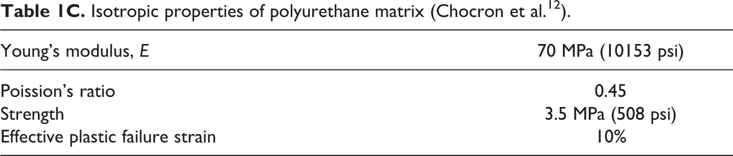
Abstract
High-performance ultra-high molecular weight polyethylene (UHMWPE) soft ballistic sub-laminates ([0/90] n , SBSL) are stacked to build a soft body armor pack (SBAP) that can defeat handgun projectiles. Transverse impact on single-layer [0/90] SBSL of different size is modeled with shell elements and is solved using LS-DYNA composite material model MAT54. The finite element (FE) model is validated using 1D and 2D theories for transverse impact. The validated FE models are then used to study the perforation behavior of a [0/90] SK76/PU SBSL under constant and variable velocity impact. Results show that the basal shape of the transverse deformation cone has a diamond shape; the cone wave speed along primary material direction agrees well with 2D membrane theory, there exists a minimum perforation velocity below which the SBSL will not perforate, the peak perforation force reduces with the size of the SBSL, and the work of perforation decreases with increasing speed. Detail perforation mechanics of [0/90] SK76/PU SBSL is presented for the first time.
Introduction
Ultra-high molecular weight polyethylene (UHMWPE) fibers, for example, Dyneema® and Spectra® fibers are used with compliant polyurethane (PU) matrix material to make [0/90] soft ballistic sub-laminates (SBSLs) for soft and hard body armor applications. 1 –3 Dyneema-Shield and Spectra-Shield are the commercial SBSLs used in soft ballistic armor applications 4 –6 for protection against handgun threats. Multiple SBSLs or shields are stacked in a soft ballistic armor pack (SBAP) that provides higher ballistic protection per unit areal weight. SBSL/shields can also be consolidated in a hot press under compression to fabricate hard ballistic body armor. 7,8 In this article, we will discuss the transverse impact on a single-layer [0/90] Dyneema SK76/PU SBSL under constant and variable velocity projectile impact in order to understand the mechanics of SBSL deformation and associated energy dissipation mechanisms.
During the transverse impact of a projectile onto a SBAP, failure of the first few sub-laminates occurs due to high stress concentration under and around the projectile followed by reduction in projectile kinetic energy and transfer of projectile momentum to the sub-laminates. During the deformation process, a dynamic cone is developed in the SBAP subjecting all the sub-laminates in the pack under membrane tension. At a certain point of time, failure of the sub-laminates stops and the dynamic cone of the remaining sub-laminates continues to grow. The sub-laminates stretch under tension providing additional resistance forces to decelerate the projectile, the projectile kinetic energy is transferred to the remaining sub-laminates, the total momentum is conserved, and the projectile is finally arrested. 9
This description of projectile defeat mechanism is qualitative and the detail mechanics is generally not well understood. The goal of this research is to study the perforation mechanics of a single [0/90] Dyneema SK76/PU SBSL that can be extended to the study of transverse impact on multilayer SBAP. In achieving the goal, we will first discuss the available material properties of UHMWPE fibers and composites, and then we will briefly review the 1D and 2D theories of constant velocity transverse impact on fibers and membranes, and finally conduct the finite element (FE) modeling of constant velocity transverse impact on a single-layer SBSL to validate the FE model. In the FE analysis section, we will develop a FE model of an isotropic membrane and validate the model with Phoenix and Porwal (P&P) 9 membrane theory for isotropic materials under constant velocity transverse impact without any boundary effects. We will then extend the validated FE model for isotropic membrane to [0/90] UHMWPE sub-laminate under constant velocity transverse impact to show the difference between an isotropic membrane and an orthotropic thin sub-laminate in a non-perforating scenario. The FE model of the [0/90] UHMWPE sub-laminate will then be extended to study the effect of laminate stacking sequence under constant velocity transverse impact. In reality, the projectile’s rigid body velocity (RBV) is decreased by the momentum transfer to the target, a theory of which does not exist in literature. In this article, we will use our validated FE model of [0/90] UHMWPE sub-laminate to study the perforation mechanics of infinite and finite size sub-laminates under variable velocity transverse impact conditions for the first time.
Properties of UHMWPE fibers, unidirectional laminas, and [0/90] sub-laminates
UHMWPE fibers are transversely isotropic in nature, however, the commercial manufactures only provide tensile modulus, strength, and tensile failure strains of these fibers (Table 1A). 3,10 –12 Recently, transversely orthotropic properties of some selected UHMWPE fibers (Table 1B) are available in literature, 12 –15 and we have calculated the transversely isotropic properties of unidirectional (UD; Table 1D) laminas using continuous fiber micromechanics. Limited experimental data on the properties of [0/90] sub-laminates are available in literature (Table 1E). 13,16 In the present analysis, we will use the properties of unidirectional Dyneema SK76/PU lamina presented in Table 1.
Transversely isotropic properties of unidirectional Dyneema SK76/PU SBSL (Table 1D; Levi-Sasson et al.).
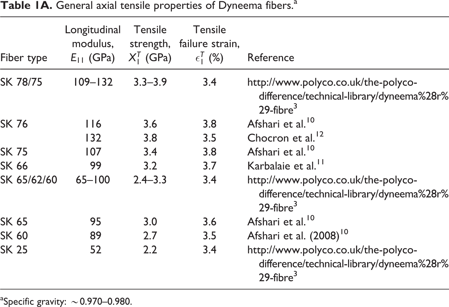
SBSL: soft ballistic sub-laminate; PU: polyurethane.
Theory of constant velocity transverse impact on isotropic elastic 1D fiber and 2D membrane
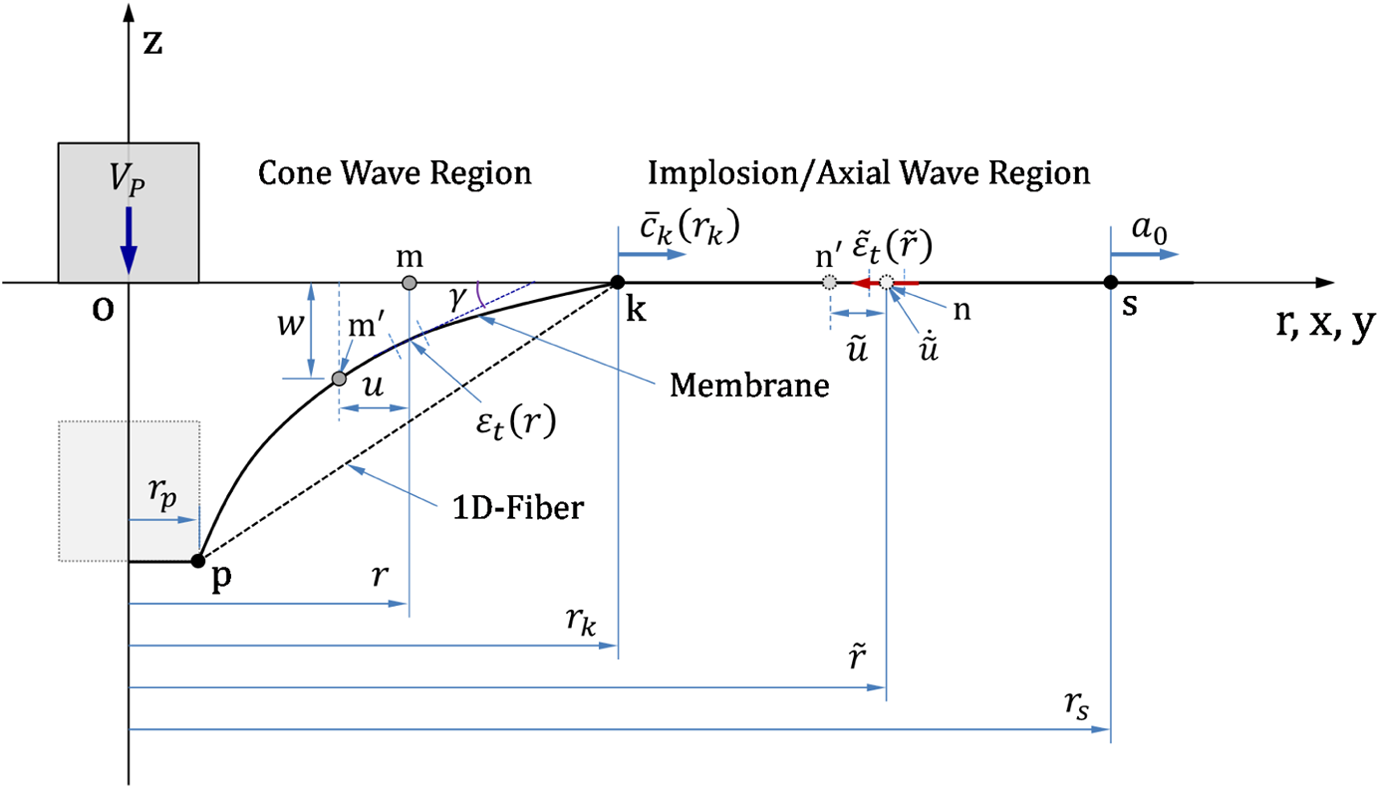
Theories of constant velocity transverse impact on 1D fiber had been developed between 1945 to 1960 by Rakhmatulin and Smith et al. 17 –24 Following these classic theories, P&P 9 has developed an axisymmetric membrane theory for constant velocity transverse impact on an isotropic elastic membrane with a cylindrical projectile (Figure 1). This article provides a good literature review on related past works on this subject including the related works on transverse impact on isotropic elastic 1D fiber. 17 –24 In the membrane theory, 2D equations are often reduced to 1D equations in P&P 9 to compare with the 1D fiber theory (Smith et al. 21,22 ). In the following sections, the classic 1D fiber theory is discussed first, followed by the 2D membrane theory. The presented derivations of key quantities and equations herein will be compared later with the FE calculations.
Nomenclature for Phoenix and Porwal9 2D membrane theory for isotropic materials.
Constant velocity transverse impact on isotropic elastic 1D fiber (Smith et al)
The classic work of Rakhmatulin
17
–20
and Smith et al.
21,22
on the transverse impact on isotropic elastic 1D fiber considers the velocity of the projectile to be constant. Upon the transverse impact of a projectile on the 1D fiber at a constant velocity VP, an implosion or axial tensile strain wave of amplitude 
The 1D cone/kink wave velocity in laboratory frame of coordinates (
And in material coordinate (ck,0) as (Smith et al.,
22
equation (7)):
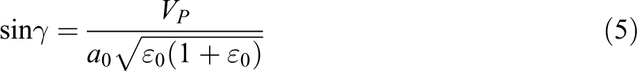
Equation (1) can be simplified to determine the approximate value of ε0 as follows (Rakhmatulin,
17
Ringleb,
24
and P&P,
9
equations (129) to (133)):
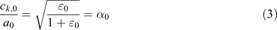
Once the value of of ε0 as a function of impact velocity (VP) and axial wave speed (a0) is known, then equations (2) and (3) can be evaluated. The 1D cone angle γ can then be calculated from P&P,
9
equation (144).
Equations (1) to (5) have been used to determine the ballistic behavior of high-performance fibers (e.g., Aramid, UHMWPE, Twaron, Zylon, Vectran, M5, etc.) by experimentally determining the fracture strain (∊f) of a fiber type and then assigning ε0 = ∊f in determining the critical impact speed (equation (1)), cone wave velocity (equations (2) and (3)), and the cone angle (equation (5)). These equations however cannot be used for SBAP and hard ballistic armor pack and were the main motivations for the P&P 2D membrane theory and are described next.
Constant velocity transverse impact on isotropic elastic membrane (P&P)
Motivated from the classic work of Rakhmatulin and Smith, P&P
9
have considered the transverse impact on an axisymmetric isotropic elastic membrane under constant impact velocity, developed necessary governing differential equations, and provided many theoretical solutions based on logical approximations. Like the 1D fiber impact model, the unknown quantities of interest are the tensile strain distribution 
Where μ = ε0 for 1D model. P&P has not provided an exact solution for implosion strain in their manuscript.
9
However, the membrane strain in the cone wave and implosion/axial wave regions is expressed together by one simple equation (P&P,
9
equations (46), (80), and (139)):

Where α = ck/a0. The cone/kink wave velocity in laboratory frame of coordinates (
where ck is the kink wave velocity in materials coordinate and 
Where n = 0, 1, 2, … and 
Equation (10) provides a slightly smaller value of
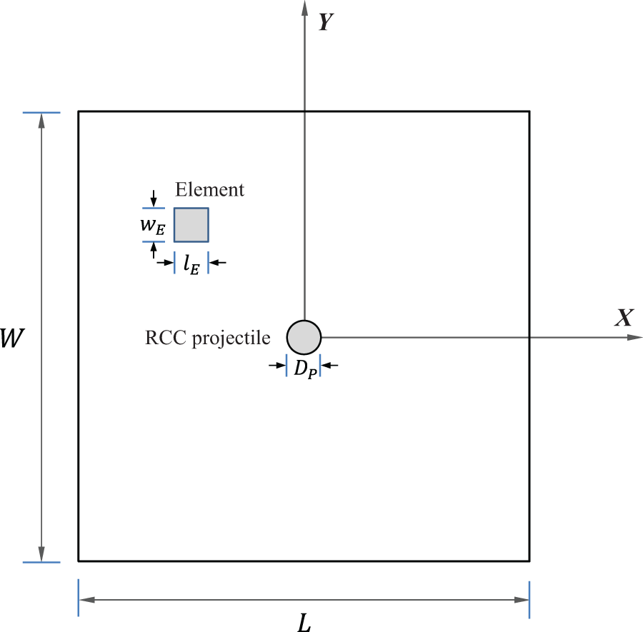
Geometric dimensions of the UHMWPE sub-laminate and coordinate definitions.
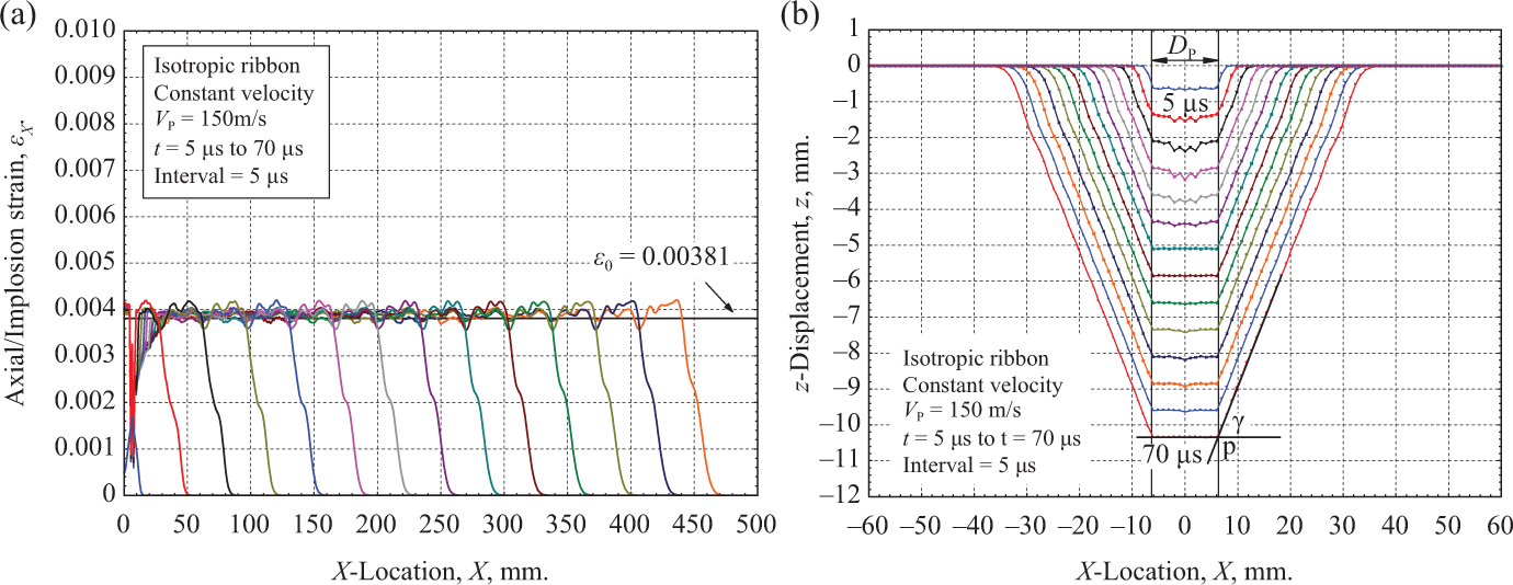
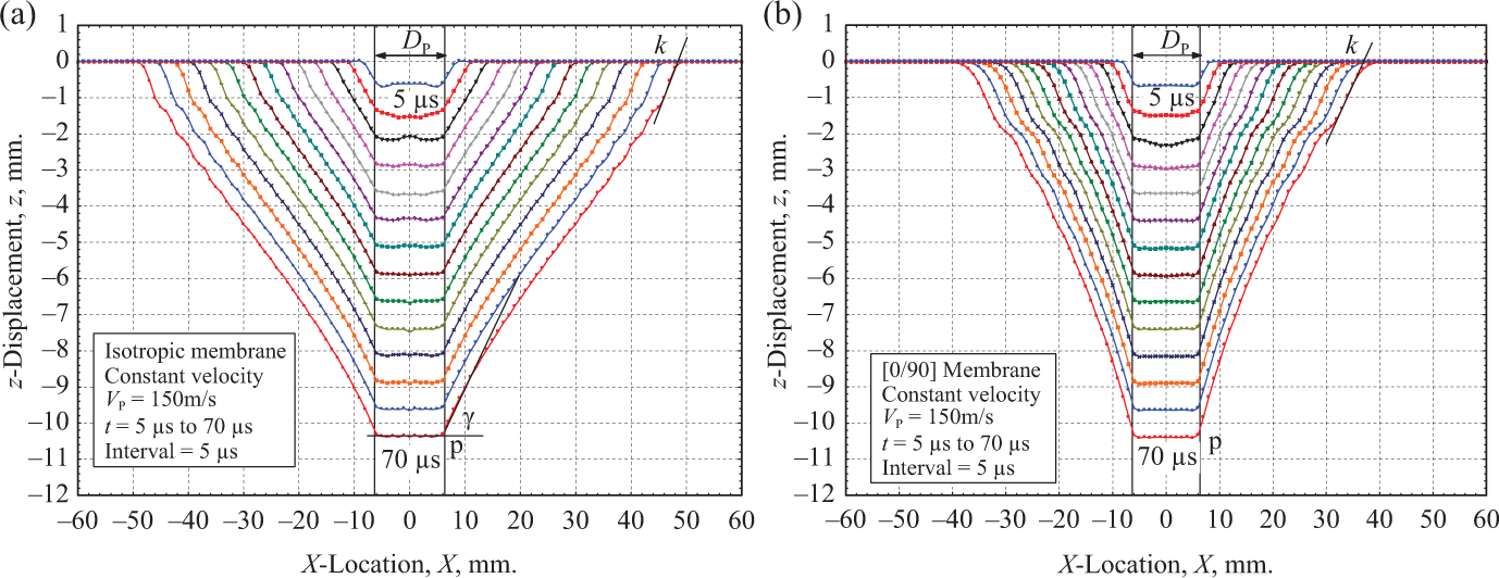
Constant velocity transverse impact on an isotropic 1D ribbon. L = 1000 mm, VP = 150 m/s, ε0 = 0.00381, [a0]1D = 6916.81 m/s, [a0]FEA = 6947.09 m/s, γ1D = 20.53°, and γFEA = 20.50°. (a) Axial strain
FE modeling
In the 1D and 2D theories, radial direction extends to infinity; however, in FE analysis (FEA), we will consider a 2D square membrane of large in-plane dimensions (e.g., lenght (L) = width (W) = 1000 mm) and terminate the computation before the implosion wave reaches the boundary of the membrane to mimic infinite boundary conditions.
FE model of a 2D membrane/shell
A single [0/90] SBSL of L = 1000 mm and W = 1000 mm is defined in the XY plane with the center of the sub-laminate located at the origin. Total thickness of all sub-laminates analyzed is taken as h = 0.127 mm. The sub-laminate is discretized with uniform shell elements (type 16) of dimensions lE = wE. A single-element study has been conducted for the fully integrated layered shell element type 16 with different hourglass types (1, 2, 4, 6, and 7) to determine the hourglass type which produces minimum hourglass energy. Hourglass type 7, which is the linear total strain form of Belytschko-Bindeman (1993) assumed strain co-rotational stiffness form for 2D shell and 3D solid elements, is found to generate minimum hourglass energy and is used in the present analysis. A mesh sensitivity analysis is performed with four mesh sizes, that is, lE = wE = 0.50, 0.75, 1.00 and 2.00 mm for the sub-laminate with dimensions L = W = 360 mm. Results presented in Appendix 2 show that a mesh size of dimension lE = wE = 1.00 mm provides comparable solution to 0.50 mm mesh, and thus all subsequent analyses are performed using 1.00 mm mesh size. Since the SBSL is composed of two UD laminas in a [0/90] stacking sequence, the *PART_COMPOSITE option of LS-DYNA has been used to define the thickness (h/2) and material angles for both the through thickness [0] and [90] laminas. Properties of the transversely isotropic UD soft ballistic lamina made from Dyneema SK76 fiber and PU matrix material is used as the input to the *MAT_ENHANCED_COMPOSITE_DAMAGE model (MAT54) for both the [0] and [90] laminas of the [0/90] SBSL and is presented in Table 1. A right circular cylinder projectile of diameter DP = 12.7 mm is used in all analyses, the mass is kept constant, and the material is considered rigid.
No boundary condition is imposed on the single-layer [0/90] SBSL model (Figure 2). The segment-based (SOFT = 2) eroding single surface contact definition with warped segment checking and sliding option (SBOPT = 5) is used between the RCC projectile and the SBSL. Considering the friction between the [0/90] SBSL and the projectile to be very low, the static and dynamic contact friction coefficients are taken as FS = 0.05 and FD = 0.03, respectively. In order to ensure accuracy of the computations, contact is searched at every time step while the time step is automatically calculated in LS-DYNA, and a time step scale factor of 0.95 is used. Since the shear modulus of the PU matrix is several order of magnitude lower than the axial modulus of the fiber, only tensile failure in the fiber direction of the UD lamina is considered. The axial tensile strength of the UD lamina (
FEM of 1D ribbon
One row of elements (1 mm mesh) along the geometric X axis of dimensions
Transverse impact on isotropic ribbon and membrane
In order to validate the suitability of the present FE analyses, the FE models of 1D ribbon and 2D membrane/shell presented in Figure 2 are considered as a single-isotropic layer of membrane elements and assigned with isotropic material properties equivalent to an equal thickness [0/90] SBSL, that is,
The characteristic time (τL) of an isotropic 1D ribbon or 2D membrane of length L is defined by the time taken by the implosion wave to propagate from the impact center at x = 0, to the edge of the ribbon at x = L/2 and reflecting back from the edge to the impact center, that is:
In order to exclude reflections from free boundaries, computations need to be terminated at time
Results and discussion
Constant velocity transverse impact on 1D isotropic ribbon
Smith equations consider a constant velocity transverse impact on an isotropic fiber (infinitely long flexible filament
21
). In the present analyses, a constant impact velocity of VP = 150 m/s on an isotropic ribbon of L = 1000 mm is simulated. The characteristic time of the 1D ribbon is calculated to be τ1000 = 144.58 μs. To avoid the effect of wave reflections from the edge/boundary, computations are terminated at time t = 70 μs. The axial strain (
The axial strain predicted from the simulation matches well with the Smith’s equation. The implosion wave front predicted by the simulation has a finite thickness (≈ 23 mm); however, in the 1D theory, the implosion wave front is a discontinuity and is the fundamental difference between the FEA and 1D theory. The average implosion wave-front velocity from the FEA is calculated by measuring the front location x at
Constant velocity transverse impact on linear elastic 2D isotropic membrane
Using the same isotropic properties as in the case of the 1D ribbon (
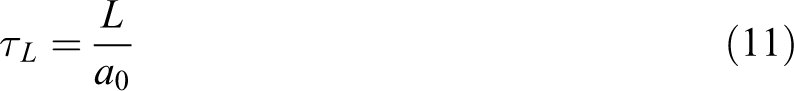
The shape of the cone wave region for the isotropic membrane and [0/90] SBSL is presented in Figure 4 for the time range t = 5 ∼ 70 μs at an interval of 5 μs. Clearly the cone wave shapes are membrane like while the cone angles at the projectile root (p) and at the kink location (k) are different. While the shape of the cone wave region for isotropic membrane is convex (outward), the shape for the [0/90] SBSL is concave (inward) with several nonlinear segments in the profile (one near the projectile root p and the other near the kink k is clearly distinguishable). While the kink location at time t = 70 μs for isotropic membrane is close to x = 50 mm, the same for the [0/90] SBSL is at x = 40 mm; which tells us that the kink wave velocity of the [0/90] SBSL is less than the isotropic membrane. Figure 5 shows the shape of the cone wave in the basal plane (XY Plane) at time t = 70 μs. The basal shape of the cone wave is circular for the 2D isotropic membrane, while the 2D [0/90] SBSL is diamond shaped (attributed to the orthotropic properties of the SBSL).
z-Displacement along X-axis on Y = 0 plane. Constant velocity transverse impact on 2-D isotropic membrane and [0/90] SK76/PU SBSL. L = W = 1000 mm, VP = 150 m/s. (a) 2D isotropic membrane; (b) 2D [0/90] SK76/PU SBSL shell. SBSL: soft ballistic sub-laminate; PU: polyurethane.
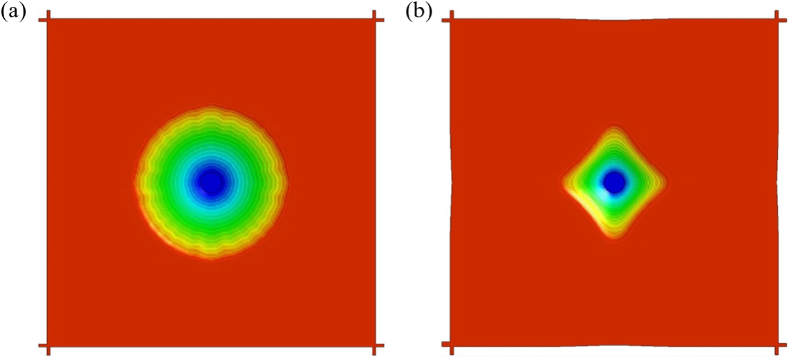
Basal shape of the cone wave at time t = 70 μs under constant velocity (VP = 150 m/s) transverse impact. L = W = 1000 mm. Snip size: 200 × 200 mm2. Contours of z-displacements: red, 0.0 mm and blue, 10.5 mm. The waviness in the circular basal cone shape may be related to the finite mesh size (1 × 1 mm2) which is not further studied for the L = W = 1000 mm isotropic membrane. (a) 2D isotropic membrane; (b) 2D [0/90] SK76/PU SBSL shell.
The cone wave velocities with respect to laboratory frame of coordinate (
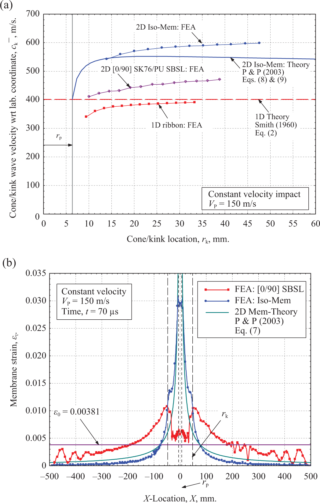
Constant velocity transverse impact on 2D isotropic membrane and [0/90] SK76/PU SBSL: Comparison between theory and FEA. L = W = 1000 mm, VP = 150 m/s. (a) Cone wave velocity
The membrane strain along X-axis in the cone wave and implosion wave region is calculated using Lagrangian description.
Where
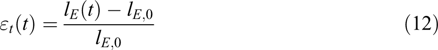
Constant velocity transverse impact on 1D isotropic fiber assumes constant particle velocity in the cone wave region; however, the 1D FEA shows (Figure 7(a)) that the particle velocity is oscillating in nature indicating bending wave propagation in the cone wave region. Similar bending wave propagation in the cone wave region of the 2D isotropic membrane is also evident in Figure 7(b). Presence of this high frequency bending wave in the cone region may be responsible for the nonuniform cone angles presented in the cone wave profiles in Figure 4(a) for isotropic membrane and in Figure 4(b) for [0/90] SBSL. Note that the 1 mm mesh size used in the present analysis is sufficient to capture the spatial distribution of high frequency bending waves as outlined in chapter 4 of Graff’s book 25 titled “Waves in membranes, thin plates, and shells.” No global damping has been used to suppress these oscillations, because of the underlying physics described by Graff. 25
z-Velocity distribution of the cone wave at two different times. L = W = 1000 mm, Constant velocity transverse impact, VP = 150 m/s. (a) 1D isotropic ribbon; (b) 2D isotropic membrane.
FEA of constant velocity transverse impact on isotropic 1D ribbon and 2D membrane provided important insight on the mechanics of implosion wave and cone wave propagation, on the spatial distribution of the membrane strain at different times, and on the particle velocities in the cone wave region. The FE results correlated well with the 1D and 2D theories with limitations of neglecting bending wave propagation. It has also been shown that the 2D membrane theory is not applicable to the [0/90] orthotropic SBSL. Further FEA with failure of [0/90] SBSL under constant velocity impact has been conducted to understand the perforation mechanics of a single-layer [0/90] SBSL shell and is presented next.
Constant velocity transverse impact on 2D [0/90] SK76/PU SBSL with failure
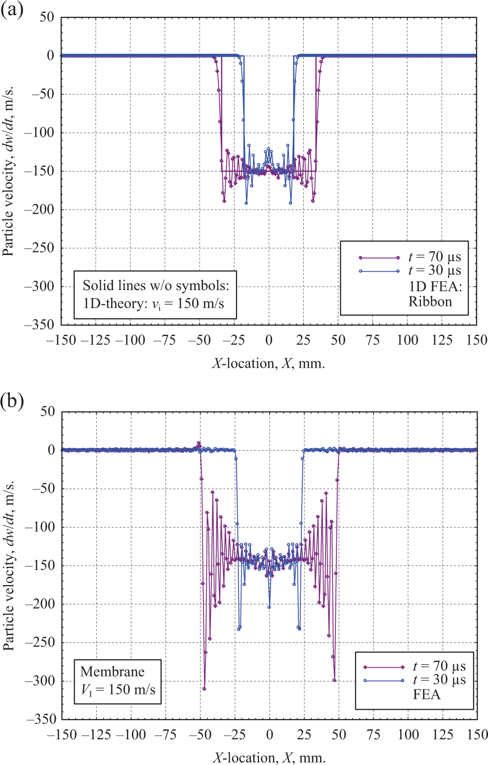
Constant velocity transverse impacts on [0/90] SK76/PU SBSL (L = W = 1000 mm) have been conducted in the impact velocity range
Perforation of a [0/90] SK76/PU SBSL under constant velocity transverse impact. L = W = 1000 mm,
From these observations, it is obvious that there exist a minimum impact velocity at which perforation will occur at t = τ1000 when the implosion wave reaches the boundary of the membrane, reflects, and travels back to the impact center. We will define this impact velocity as the minimum perforation velocity,
Figure 8(b) shows the FP versus projectile displacement under constant velocity transverse impact cases presented in Figure 8(a). Force–displacement plot up to a projectile displacement z ≈ rp is somehow oscillatory in nature which is attributed to the loss and reestablishment of contacts between the membrane and the projectile in the early stage of cone wave formation. Stable growth of the cone wave and continuous contact beyond z ≈ rp yields almost a linear force–displacement response till the perforation of the [0/90] SBSL membrane at the peak force 
The membrane stiffness defined by equation (13) increases with impact velocity, and for impact velocities at 155 m/s and 200 m/s are calculated to be approximately 71 and 95 N/mm, respectively, indicating the fact that structural stiffness of the membrane increases with the increase of impact velocity due to dynamic effects (the mechanics is not formulated here). The area under the force–displacement curve represents the work of perforation, WP, and is listed for each impact velocity in the legend.
Work of perforation decreases with increase in impact velocity; however, the detail mechanics is not known/ formulated. Time sequence of perforation of the SBSL at VP = 150 m/s is presented in Figure 9 along with the perforation force time history. A sharp drop in the force time history represents the initiation of failure in the [0/90] SBSL and is found to occur at time t ≈ 142 μs, signifying the initiation of the failure process. Load drops continuously revealing the first element erosion (mimicking fiber tensile fracture) between 150 μs and 160 μs and most probably at around t ≈ 156 μs. For time greater than 160 μs, Figure 9(d) to (f), dynamic propagation of the fiber fracture continues yielding complete perforation (CP) of the SBSL at time t = 200 μs, where the resistance force drops to zero.
Perforation behavior of a single-layer [0/90] SK-76/PU SBSL under constant velocity impact at VP = 150 m/s. L = W = 1000 mm,
Constant velocity transverse impact on 2D SK76/PU SBSL with different stacking sequence
The cone wave of a [0/90] SBSL is found to have a diamond shape in the basal plane (Figure 5(b)) as compared to the isotropic circular shape (Figure 5(a)). Also, the z-displacement profile of the [0/90] SBSL is significantly different than the isotropic membrane (Figure 4). The difference in cone shape at the basal plane and the z-displacement profile is thought to be the main reason of lower kink/cone wave velocity of the [0/90] SBSL (Figure 6(a)) than the isotropic membrane. In order to understand the effect on stacking sequence of the SBSL, we have modified the composite laminate architecture from two to four layers while keeping the total SBSL thickness constant, that is, h = 0.127 mm. Four SBSL stacking sequences have been studied under a constant velocity transverse impact of VP = 150 m/s, and they are (a)
Figure 10 shows the shape of the cone wave at the basal plane of these SBSLs at time t = 70 μs. z-Displacements along X- and Y-axes are plotted (Figures 3A
to 3D, Appendix 3) to determine the kink/cone wave velocities and the cone angles for different SBSL architecture and are presented in Figure 11(a) and (b), respectively. From the FE simulation results, insignificant differences in quantities along X- and Y-directions have been observed for all laminates (except
Basal shape of the cone wave at time t = 70 μs under constant velocity (VP = 150 m/s) transverse impact for different laminate stackings. L = W = 1000 mm. Snip size: 120 × 120 mm2. Horizontal (→) direction is the X-direction and vertical (↑) direction is the Y-direction. (a) [0°/0°/90°/90°]; (b) [0°/+45°/−45°/90°]; (c) [+45°/+45°/−45°/−45°]; and (d) [+22.5°/+22.5°/−22.5°/−22.5°].
Average cone/kink wave velocity and cone angle along X-direction (→) as a function of time for different laminate architecture. Constant velocity (VP = 150 m/s). Transverse impact, L = W = 1000 mm. (a) Cone/kink wave velocity; (b) cone angle.
Variable velocity transverse impact on 2D [0/90] SK76/PU SBSL with failure
As mentioned in the introduction, projectile velocity continuously changes during the impact on a target and the cone wave velocity may also continuously change with the changing velocity of the projectile. A theoretical model for projectile with continuously changing velocity impacting a membrane does not exist in literature, and FEA is thus essential. With the fundamental understanding of constant velocity transverse impact on the perforation mechanics of a [0/90] SBSL, we will now present the variable velocity impact on the [0/90] SBSL of dimension L = W = 1000 mm and then extend the study to SBSL of finite dimensions, that is, L = W = 500, 360, 250 mm. In case of variable velocity transverse impact, we will denote the initial impact velocity at time t = 0 by VI and the instantaneous RBV of the projectile at any time t by V(t) and will present the projectile dynamics by plotting the time history of projectile RBV and FP and cross-plot the resistance force versus projectile rigid body displacement (RBD) to gain insight of the perforation mechanics. A right circular cylinder (RCC) projectile of diameter, DP = 12.7, and of mass, mP = 12.61 g is used for the variable velocity impact analyses.
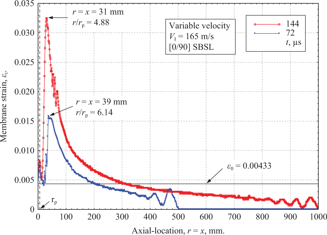
Figure 12 shows the time history of projectile RBV and FP of a 1000 mm SBSL under a wide range of impact velocities (

Time history of projectile velocity and perforation resistance force. Variable velocity impact (
Variable velocity perforation data of [0/90] SK76/PU SBSL, L = W = 1000 mm,
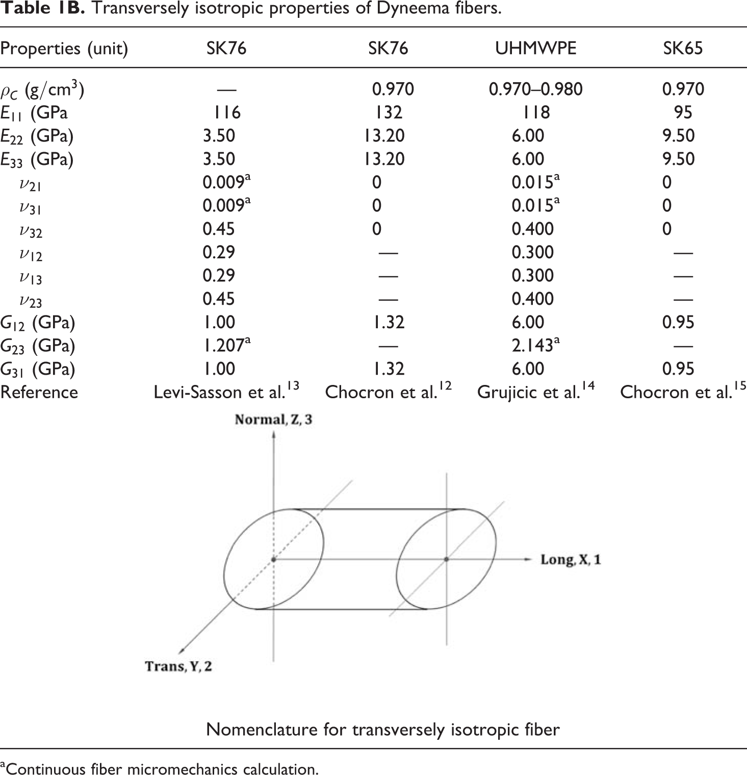
SBSL: soft ballistic sub-laminate; PU: polyurethane; NP: no perforation; CP: complete perforation.
aAverage of complete perforation (CP) values.
Figure 13(a) shows the FP plotted with projectile RBD (
Time history of projectile velocity and perforation resistance force. Variable velocity impact (
Table 2 shows the perforation data of all perforating impacts. In obtaining the perforation in the time range
According to the 2D membrane theory for isotropic materials (P&P
9
), the membrane strain is (equation (7)) is a function of ck, which is a function of constant impact velocity VP. For a variable velocity impact, projectile velocity is decreasing at every instant and thus ck is also changing at every instant. P&P further modified the 2D membrane theory in the study of woven fabrics where they have derived few equations (equations (179) to (182), (213), and (214) in P&P) for strain concentration, K, value of which is 1.00 at
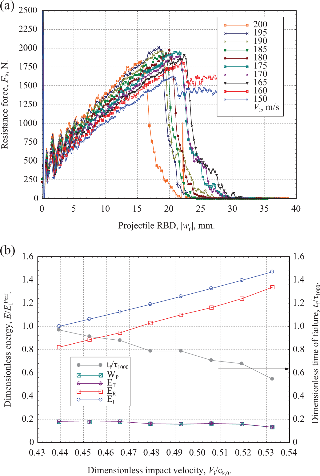
Membrane strain along X-axis of [0/90] SBSL. Variable velocity impact, VI = 165 m/s. L = W = 2000 mm,
In order to avoid axial/implosion wave reflection from the free edges, simulations are conducted on a larger [0/90] SBSL of dimension L = W = 2000 mm. Considering symmetry, data along the positive X-axis are presented in Figure 14 which shows the membrane strain along X-axis of a [0/90] SBSL under the variable velocity perforating impact of VI = 165 m/s, at two different time, that is, at t = 72 and 144 μs (t/τ2000 = 0.249 and 0.498), respectively. At time t = 72 μs, the axial/implosion wave front reaches at x = r = 500; and at time t = 144 μs, the axial wave front reaches x = r = 1000 mm. Thus the membrane strains plotted in Figure 14 do not have any boundary effects. The membrane strain profile for the [0/90] SBSL is very similar to the strain concentration profile of P&P (Figure 4(a) and (b) in P&P) and thus qualitatively agrees well with the P&P membrane theory. The exact axial/radial locations where the strain concentrations occur in the membrane strain profiles are identified in Figure 14.
Variable velocity transverse impact on finite size 2D [0/90] SK76/PU SBSL
In order to study the effect of boundaries on the perforation mechanics of finite size [0/90] SBSLs, we have performed similar analysis on three different finite size SBSLs, namely, L = W = 500, 360, and 250 mm.. Time history of RBV of the projectile and the FP of L = W = 360 mm [0/90] SBSL is presented in Figure 15 and the same for L = W = 500 and 250 mm [0/90] SBSLs are presented in Figures 4A and 4B in Appendix 4.
Time history of projectile velocity and perforation resistance force. Variable velocity impact (
For finite size [0/90] SBSLs, perforation occurs at
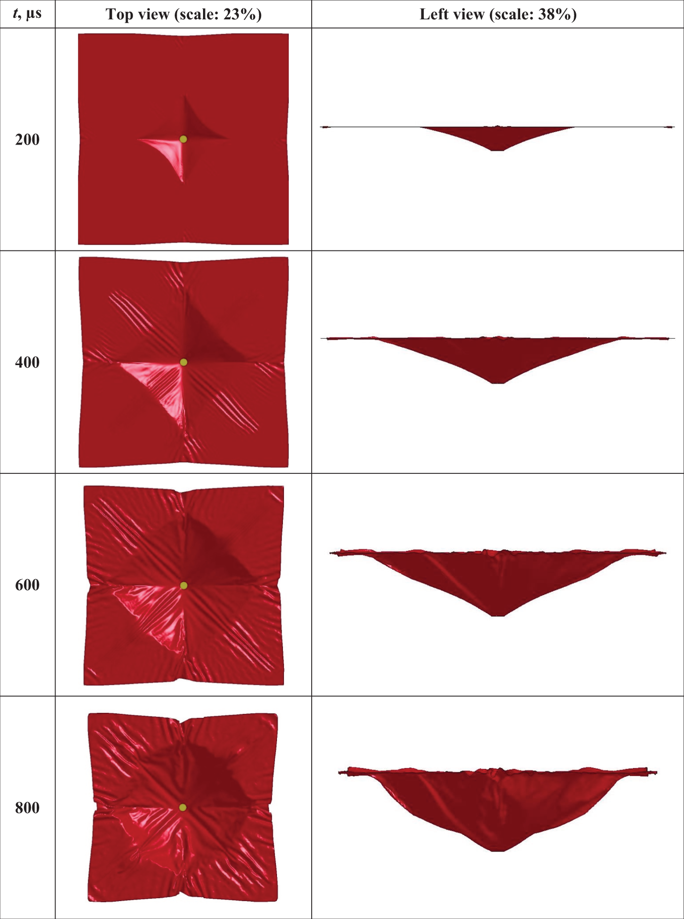
Large deformation modes of finite size SBSL. Variable velocity impact, VI = 125 m/s, L = W = 360 mm.
In case of impact velocities lower than the perforation velocities, finite size SBSBs deform like a cone and move at a constant velocity with the projectile for time
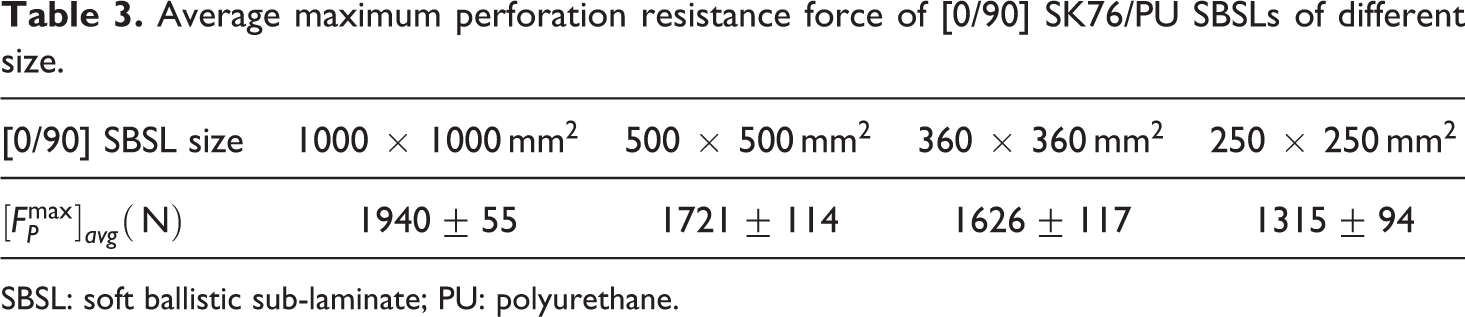
Average maximum perforation resistance force of [0/90] SK76/PU SBSLs of different size.
SBSL: soft ballistic sub-laminate; PU: polyurethane.
Understanding the large deformation modes and the perforation mechanics of finite size SBSLs are important in understanding the variable velocity transverse impact on multilayer SBAP. Preliminary studies on the perforation mechanics of a SBAP made from 32 layers of 360 mm [0/90] SBSLs have been performed by the authors 26 and further detail will be presented elsewhere.
Summary
Constant velocity transverse impacts on a 1D isotropic ribbon, on a 2D isotropic membrane, and on a 2D [0/90] SK76/PU soft ballistic sub-laminate (SBSL) have been presented using LS-DYNA FEA. Theories of 1D fiber and 2D membrane are compared with the FEA results to validate the suitability of the FE model for further analysis. It is well known that both 1D Smith equations and 2D membrane theory (P&P 9 ) assumes perfect contact between the fiber/membrane and the impactor and ignores bending wave propagation. However, the present FEA shows that both the ribbon and membrane under the projectile have oscillatory contact behavior, and the particle velocities in the cone wave region along the direction of impact are oscillatory in nature prevailing bending wave propagation in the cone wave region. While the basal cone shape is circular for isotropic membrane, the same for the [0/90] SK76/PU SBSL is found to be of diamond (or square) shape and not cylindrically symmetric. Thus the cylindrically symmetric 2D isotropic membrane theory cannot be used in the analysis of [0/90] SBSL. It has also been identified that the cone wave speed of [0/90] SK76/PU SBSL along the primary material axes ([0], 1) starts at the 1D value and shows a nonlinear increase with time reaching a plateau value for long time. The effect of laminate stacking sequence on the cone wave velocity and cone angle has been quantified. A characteristic time and minimum perforation velocity of a SBSL of finite dimension is defined and determined for a 1000-mm [0/90] SK76/PU SBSL under constant velocity impact.
Perforation mechanics study of a [0/90] SBSL where the projectile velocity continuously changes was one of the main goal of this research. Following the lessons learned from the constant velocity impact problems, FP of a 1000-mm [0/90] SBSL have been predicted using the FE model at different impact velocities such that the perforation occurs in the time range
In gaining insight into the perforation mechanics of finite size SBSLs, three different finite sizes are chosen, that is, L = W = 500, 360, and 250 mm. Time history of projectile velocity, displacement, and FP have been analyzed to determine the minimum perforation velocity and dissipated energy. Because of finite size, failure of the SBSLs have been observed at
Footnotes
Appendix 1. Properties of UHMWPE fibers,unidirectional soft-ballistic lamina,and [0/90] sub-laminate
Orthotropic properties of [0/90] SK 76/PU SBSL.

| Properties (unit) | HB26-[0/90] composite | HB26-[0/90] composite | HB26-[0/90] composite |
|---|---|---|---|
| vf (%) | — | 72 | 37.2 |
| ρC (g/cm3) | — | — | — |
| E11 (GPa) | 26.9 | 43.9 | 22.31 |
| E22 (GPa) | 26.9 | 43.9 | 22.31 |
| E33 (GPa) | 3.62 | 3.65 | 1.116 |
| ν 21 | — | — | — |
| ν 31 | — | — | — |
| ν 32 | — | — | — |
| ν 12 | 0.0 | 0.0238 | 0.0133 |
| ν 13 | 0.1 | 0.0188 | 0.0144 |
| ν 23 | 0.5 | 0.0188 | 0.0144 |
| G12 (GPa) | 0.0423 | 1.118 | 0.4044 |
| G23 (GPa) | 0.0307 | 8.828 | 0.3682 |
| G31 (GPa) | 0.0307 | 8.828 | 0.3682 |
| Reference | Lassig et al. 16 | Levi-Sasson et al. 13 | Levi-Sasson et al. 13 |
SBSL: soft ballistic sub-laminate; PU: polyurethane.
Appendix 2: Mesh sensitivity analysis
A mesh sensitivity analysis is performed with four different mesh sizes, that is,
The solution time for mesh sensitivity analyses is chosen to be t = 1000 μs which is 19 times higher than the characteristic time (
Finer mesh predicts better folding and pull-in behavior in the primary material directions, however, the choice of 1 mm mesh preserves almost all deformation behavior that can be seen for 0.50 mm mesh (Figure 2D(a) and (b)).
Appendix 3: Constant velocity transverse impact on SBSLs with different laminate architecture
Appendix 4: Perforation mechanics of finite size SBSL
Variable velocity perforation data of [0/90] SK76/PU SBSL, L = W = 250 mm,
|
|
CP/NP |
|
tf (μs) |
|
|
EI (J) | ER (J) | ET (J) | WP (J) |
|---|---|---|---|---|---|---|---|---|---|
| 100 | NP | — | — | 680.7 | — | 63.0 | — | — | — |
| 125 | NP | — | — | 963.0 | — | 98.5 | — | — | — |
| 130 | NP | — | — | 1008.8 | — | 106.5 | — | — | — |
| 135 | NP | — | — | 1061.8 | — | 114.9 | — | — | — |
| 140 | NP | — | — | 1124.8 | — | 123.5 | — | — | — |
| 145 | CP | 119.7 | 297.71 | 1163.3 | 8.238 | 132.5 | 90.4 | 42.2 | 42.3 |
| 150 | CP | 126.7 | 282.70 | 1212.2 | 7.822 | 141.8 | 101.2 | 40.6 | 40.6 |
| 160 | CP | 134.6 | 231.92 | 1332.8 | 6.417 | 161.4 | 114.3 | 47.1 | 46.9 |
| 170* | CP | 137.8 | 198.62 | 1339.0 | 5.496 | 182.2 | 119.6 | 62.5 | 60.2 |
| 180 | CP | 163.4 | 152.39 | 1353.6 | 4.217 | 204.2 | 168.3 | 36.0 | 35.9 |
| 190 | CP | 174.2 | 150.31 | 1377.0 | 4.159 | 227.5 | 191.2 | 36.3 | 36.1 |
| 200 | CP | 185.0 | 105.70 | 1430.5 | 2.925 | 252.1 | 215.8 | 36.4 | 36.1 |
| Average |
|
SBSL: soft ballistic sub-laminate; PU: polyurethane; NP: no perforation; CP: complete perforation.
aA ribbon was moving with the projectile, and thus the energy transfer and work done is an outlier in the sequence.
bAverage of complete perforation (CP) values.
Declaration of Conflicting Interests
The author(s) declared no potential conflicts of interest with respect to the research, authorship, and/or publication of this article.
Funding
The author(s) received no financial support for the research, authorship, and/or publication of this article.