
Abstract
Drilling is the most widely used machining process in manufacturing holes in many industrial applications. Optimizing the drilling process is a key to improve the hole quality. Therefore, numerical modeling is an effective method that gives an idea about the cutting process to optimize the drilling parameters. This paper emphasizes the sensitivity of the thrust force, the torque and the machining-induced damage to the hole saw tool geometry using a 3D Finite Element (FE) model developed using ABAQUS/Explicit. A Johnson cook model associated with a ductile damage law is used to predict the failure mechanism of a random chopped glass fiber reinforced polyester. It is found that the thrust force, the torque and the damage around the hole obtained from the FE model are in good agreement with the experimental data. Differences of about 2% for the thrust force, 2.4% for the torque and 3% for the damage around the hole are observed. The results of the numerical model also indicated that the thrust force as well as the drilled workpiece quality are improved by choosing the suitable rake angle. A decrease of about 61% in the thrust force is observed when varying the rake angle from 0° to 20°. However, the latter has an insignificant effect on the thrust force. Furthermore, it can be concluded that this parameter highly influences the material removal process.
Introduction
In the last decade, the use of composite materials has increased in many fields such as aerospace, marine, civil and electronics thanks to their lower mass, higher stiffness and chemical resistance. Despite the extensive research on composite materials, several operations relating to the manufacture of composite parts, in particular its machinability remain a challenge. It should be noted that more than 40% of the material removal process is drilling. 1 However, the inherent characteristics of composites like anisotropic, heterogeneous and highly abrasive fibers, make the drilling operation difficult to achieve and cause many defects such as fiber pull-out, 2 burr 3 and delamination. 4 The latter covers 60% of all defective parts in aircraft industry. 5 In order to minimize the drilling defects, it is crucial to select the appropriate drilling parameters. In this context, several studies have investigated the effect of cutting parameters on drilling-induced delamination. Ficici et al. 6 performed a series of experimental tests, using HSS, TiN-coated HSS and carbide drills, to study the effect of the cutting speed and the feed rate on delamination and surface roughness during the drilling of a Unidirectional Glass Fiber Reinforced Polymer (UD-GFRP). Their results showed that delamination and surface roughness would decrease by raising the cutting speed and reducing the feed rate. This finding was also reported by Phadnis et al. 7 and Rajmohan et al. 8 Tian et al. 9 demonstrated that a high spindle speed and a low feed rate were the best cutting conditions for achieving a minimal damage when drilling the GFRP using a candlestick drill. Kim et al. 10 recommended a low feed (0.12 mm/rev) and a high speed (5440 rpm) when drilling PIXA-M- and PEEK-thermoplastic composites. Based on the experimental design when drilling Sheet Molding Compound (SMC) composites, Can and Ünüvar 11 revealed that the minimum thrust force and peel-up delamination were obtained for a cutting speed of 56 m/min. They also found that minimal push-out delamination was found for a high cutting speed (80 m/min) while the low cutting speed (40 m/min) gave minimal surface roughness.
Other researchers have examined the effect of material constituents on the thrust force and torque. Merino-Pérez et al. 2 carried out experimental drilling tests on the carbon / epoxy composite to study the effect of material constituents on the thrust force and torque. Two types of thermosetting resins (MTM28B, MTM44-1) and two types of carbon fibers (CF0300, CF2216) were tested. They found that the type of resin had a significant effect on the thrust force. However, the influence of the type of fiber was considered negligible. Moreover, they found that the torque was considerably influenced by the composite constituents. Indeed, the maximal thrust force and torque were observed for the resin, which had high thermomechanical properties (elastic modulus and glass transition temperature). Abdul Budan et al. 12 studied the effect of the fiber content on surface roughness and delamination when drilling a woven glass fiber composite. They found that surface roughness and delamination increased with the rise in the percentage of fibers. López De Lacalle et al. 13 examined the effect of composite properties on the cutting force when milling two types of composites. The first one was a carbon fiber-reinforced epoxy, the second one was a carbon, and Kevlar fibers reinforced epoxy. They revealed that the cutting force of composite with Kevlar and carbon fibers was higher than those with carbon fibers. This was due to the high strength and modulus of composite with Kevlar and carbon fibers as compared to the other ones.
Several researchers have studied the effect of the tool geometry parameters on the cutting force, the thrust force and the delamination. Using 2D Finite Element (FE) model of orthogonal cutting of UD-GFRP, Nayak et al. 14 investigated the effect of the rake angle on the cutting force, the thrust force and the subsurface damage. They observed that both forces decrease with the increase of rake angle. The minimum forces and damage are detected for a 30° rake angle. Jia et al. 15 reported that machining the Unidirectional Carbon Fiber Reinforced Plastic (UD-CFRP) with a 135° fiber orientation leads to the decrease of cutting force and the depth of subsurface damage when the rake angle varies from 0° to 30°. Beyond 45°, these machinability outputs decrease. Wang et al. 16 examined the influence of the clearance angle on both cutting and thrust forces during the machining of the UD-CFRP. They revealed that thrust force decreases with the increase of clearance angle, but this parameter does not affect cutting force. Singh et al. 17 analyzed the effect of the drill point angle of a twist drill on the thrust force and the delamination during the drilling of the UD-GFRP. They found that the thrust force and the delamination increase with widening of the drill point angle. Marathe and Javali 18 established experimental drilling tests on a composite of unsaturated polyester resin and chopped glass fibers to examine the effect of the drill point angle on the specific cutting energy. They found that the low amount of specific cutting energy was obtained for a small drill point angle, which improve the efficiency of machining.
Numerous studies have found that the design of several new drill bits can reduce the thrust force, i.e. delamination, burrs and fibers pullout. Among these drill tools, it is worth mentioning the saw drill, the step drill,19,20 the one shot drill bit, 21 the reamer drill, 22 the dagger drill 23 and the one shot drill with intermittent-saw tooth structure, 24 and the candle stick drill. 25
Most of the previous studies have focused on machining woven or unidirectional fiber composites. In the literature, research on drilling random short fiber composite has been very limited.11,26 Additionally, research on the effect of tool geometric parameter has been mostly concentrated on reducing the drilling damage by utilizing multi-stage drill bits. However, ideas of changing the action point of force by distributing the thrust force in the drill periphery and minimizing the contact area between the tool and the workpiece has rarely been considered in the tool design.
This paper proposes a new tool design (hole saw) for drilling the SMC. This work is part of an industrial collaboration, which aims to enhance the quality of a drilled SMC composite by varying the hole saw tool geometry. For this purpose, a 3D FE model simulating the drilling of composites is developed upon ABAQUS/Explicit. The obtained numerical results are compared to the experimental findings. The developed model emphasizes the effect of the tool geometric parameter, particularly the rake angle on the thrust force, the torque, the workpiece damage and the material removal process. The FE model is found to be very beneficial in highlighting the significant role of hole saw tool geometry as regards controlling the thrust force and the hole quality.
Experimental procedure and FE modeling
Experimental procedure
The drilling tests are achieved using a milling machine with a maximal speed of 6000 rpm. All tests are carried out at an ambient environment under dry conditions. The spindle speed and the feed rate are fixed at 1000 rpm and 300 mm/min, respectively. Figure 1 illustrates the experimental set up where the specimen is fixed with clamps to a support plate and the multi-tooth drill (hole saw tool) is attached to a tool holder. The thrust force and torque are measured using a Kistler piezoelectric dynamometer type 9257B.
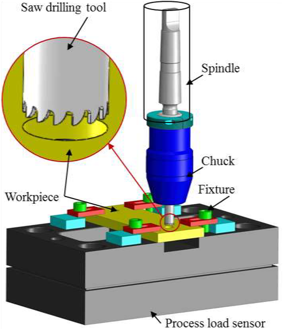
Experimental setup.
The composite specimens with common dimensions of 70 × 50 × 3 mm3 are made of a 65 wt% short glass fiber with an average length of 25 mm27 embedded in a polyester matrix loaded with calcium carbonate CaCO3 particles (SMC-R65).
The SMC is manufactured by dispersing long strands of chopped fibers on a bath of thermoset resin to obtain a prepreg. After that, the prepreg is cured and then compression molding is applied.
For reasons of confidentiality, some details of the geometry and the material of tool are not mentioned in this paper.
FE modeling
FE model, mesh construction and boundary conditions
To highlight the sensitivity of the drilling process to the tool geometry, a 3D FE model based on the Lagrange formulation is developed using the ABAQUS-Explicit software. Figure 2 shows the tooth geometry of the hole saw tool, the FE model, the boundary conditions (BCs) and the mesh. The tool teeth has a 0° rake angle and a 0.01 mm edge radius. The tool is supposed to be rigid owing to its high elastic stiffness compared to the composite material. The workpiece is considered as a deformable body with a dimension of 17 × 17 × 3 mm3. The tow lateral sides of the workpiece are constrained while the other ones are restrained from translation in the x direction. The rotational and translational velocities in the z direction are applied to the tool reference point. The spindle speed and the feed rate are 1000 rpm and 300 mm/min, respectively.
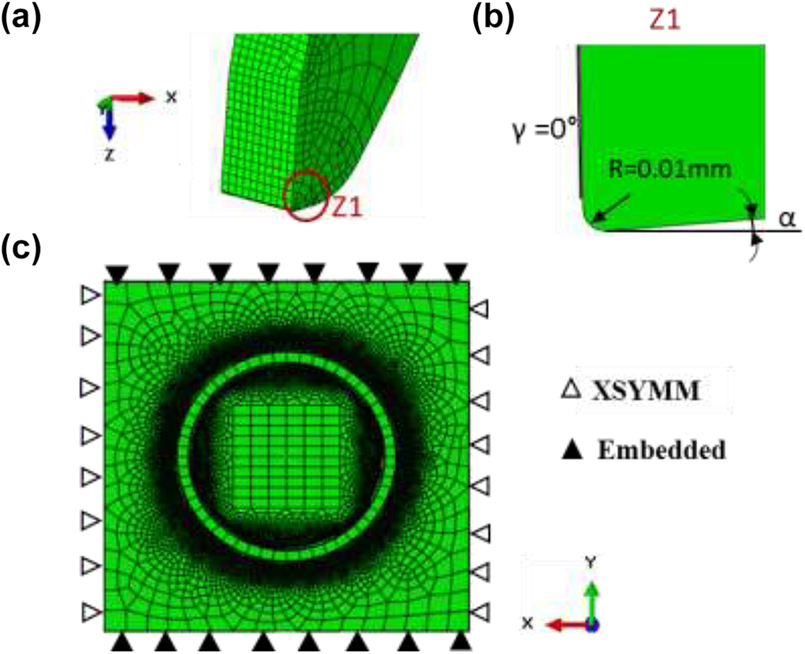
(a) Tooth geometry of the hole saw tool, (b) Zoom of Z1, (c) FE model, mesh construction and boundary conditions.
The proper selection of the mesh type and size is a key factor in the numerical convergence. In this model, the workpiece is meshed using eight-node linear brick elements with reduced integration and distortion control (C3D8 R). The hole saw tool is meshed with four-node 3D bilinear rigid quadrilateral elements (R3D4). Fine meshes with a minimal element size of 2µm are applied in the contact zone while coarse meshes are applied elsewhere to obtain a good compromise between reasonable computation time and accuracy of results. Subsequently, the workpiece is composed of 2,353,950 elements and the drill consists of 20,684 elements.
The interaction between the tool and the workpiece is modeled using a surface-to-surface contact with a constant friction coefficient of 0.3.28,29
Material behavior
Behavior law
The random chopped glass fiber-reinforced polyester composite used in this study is assumed to be an isotropic elastic-plastic material.22,25–26,30,31 Young’s modulus and Poisson’s ratio characterize the linear elastic behavior. The plastic behavior is governed by the Johnson Cook model neglecting the effects of the strain rate and the temperature. This constrictive model has been used in the literature to describe the behavior law of composites.27–28,32,33 The equivalent plastic flow stress as a function of the equivalent plastic strain is expressed by equation (1) 34 :

where A is the yield strength, B is the strain hardening modulus (linear parameter of strain hardening), and n is the coefficient of strain hardening (non-linear parameter of strain hardening).
Damage law
In the literature, the short fiber composites has been modeled based on the principle of the progressive damage behavior. 30 Therefore, the ductile damage law is employed to emphasize the damage initiation and evolution due to the nucleation, growth and coalescence of voids in the workpiece. This law acts on the mechanical properties of the material by involving damage variable “D”, which is equal to 1 when the material loses its load capacity.
Damage initiation
The model assumes that the equivalent plastic strain
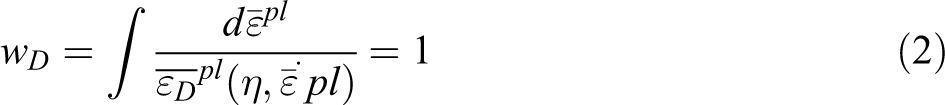
Damage evolution
A linear evolution of damage variable with an effective plastic displacement is assumed. The damage variable is expressed by equation 35 :
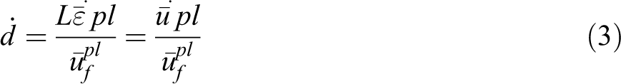
where L is the characteristic length of the element, and
Equation reveals that when the effective plastic displacement is equal to the effective plastic displacement at failure, the material stiffness will be fully degraded (d = 1).
It is worth noting that the elements are deleted from the mesh once the overall damage variable D reaches the maximal degradation.
Variable D detects the combined effect of all active damage mechanisms and is calculated as a function of the individual damage variables (di).
The output variable SDEG represents the overall scalar stiffness degradation, which contains the value of D.
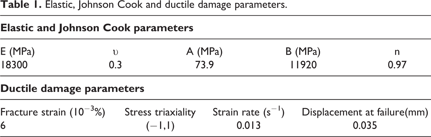
Table 1 denotes the elastic, Johnson Cook and ductile damage parameters of the random chopped fiber composite. E, A, B, n, the fracture strain and the strain rate are identified by the inverse approach through the traction curve of Chaturvedi et al. 36 Poisson’s ratio (υ) is determined from. 27
Elastic, Johnson Cook and ductile damage parameters.
Results and discussion
Comparison between numerical and experimental results
Verification of the thrust force and torque
The numerical drilling results of the chopped glass fiber composite are presented in this work under the same experimental conditions. The evolution of the thrust force and the torque versus time is displayed in Figure 3(a) and (b), respectively. It can be noted that there are two domains: (i) In the first one (D1), the hole saw tool penetrates into the sample, inducing a sharp increase in the thrust force and the torque. (ii) In the second one (D2), the hole saw tool is totally in contact with the workpiece and the quantity of removed material is increased. In this case, the thrust force and the torque are in a steady state. The fluctuations in the numerical thrust force and the torque are probably due to the contact noise generated by the mesh as well as the impact of the element deletion at the tool edge.
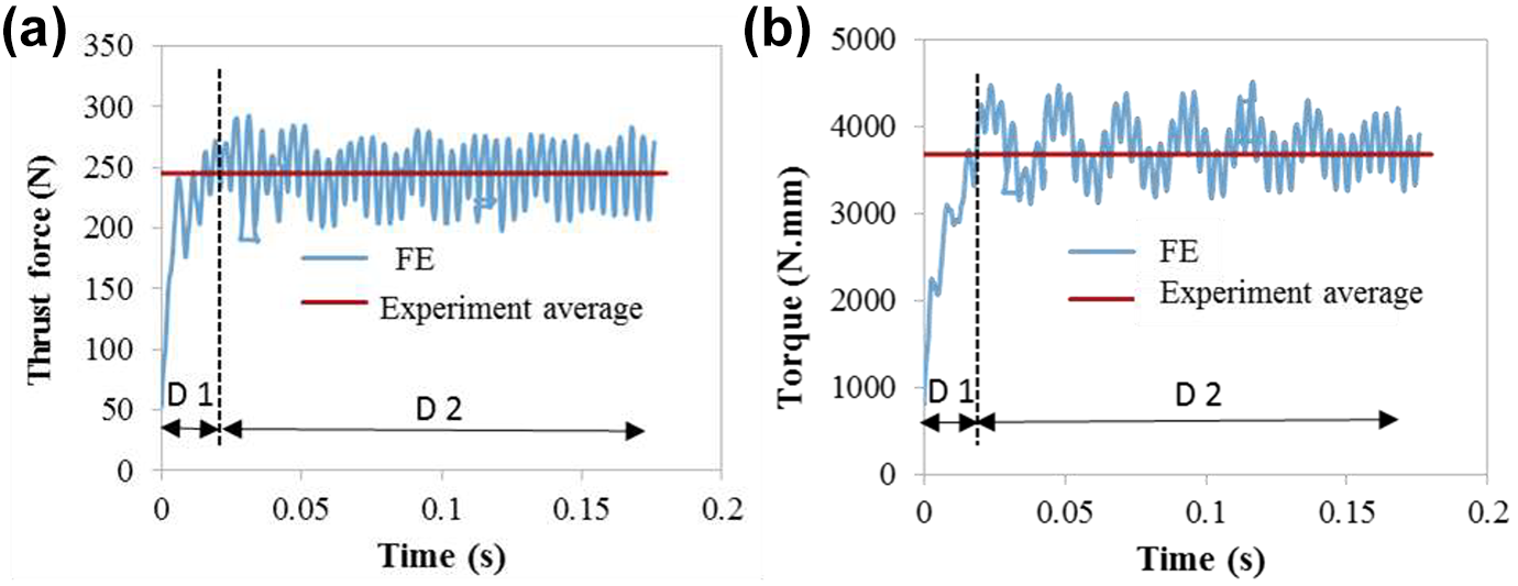
Comparison between numerical and experimental results: (a) thrust force and (b) torque.
The accuracy of the FE model is tested by comparing the numerical and experimental results. It is shown from Figure 3(a) that the predicted thrust force and the experimental one exhibit a good concordance with a discrepancy of about 2%. Similar ascertainment is found for the torque (Figure 3(b)) with a discrepancy of about 2.4%.
Validation of damage
Figure 4(a) displays the ductile damage in the workpiece at the hole entrance. The red area (Dm), which is equal to 11.35 mm, show the damage distribution in the workpiece that causes the strength decrease in the composite structure. Figure 4(b) shows a schematic representation inspired from the microscopic analysis of the experimental damage area at the hole entrance. The experimental damage area is about 11.1 mm. It can be noticed that the gap between the numerical and experimental results does not exceed 3%. This good concordance validates and supports the developed numerical model.
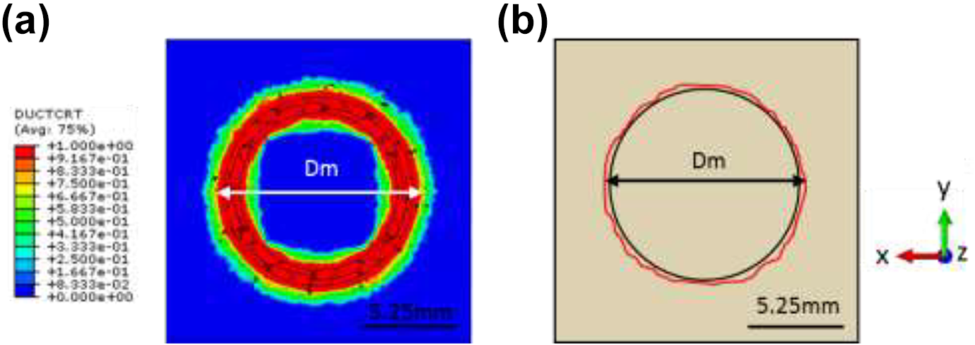
Damage prediction in workpiece for (a) numerical observation and (b) schematic representation inspired from experimental observation.
Optimization of the hole saw tool geometry: Rake angle
Prediction of thrust force and torque
As depicted in Figure 5, the primary shear generating the chip results from the action of the tool rake face on the workpiece material. Thus, the rake angle is considered as an important parameter in controlling the chip formation and hence the surface integrity.
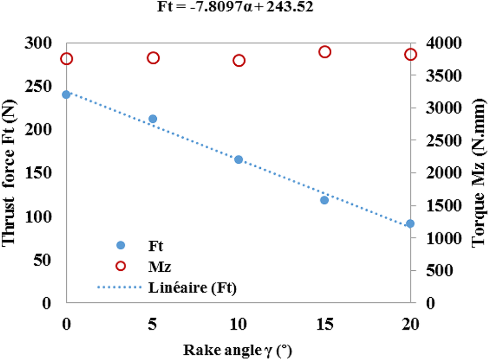
Effect of rake angle on thrust force and torque.
In order to evaluate the influence of the tool geometric parameter, particularly the rake angle on the thrust force and the torque during the drilling of the random chopped fiber composite, series of rake angles [0°, 5°, 10°, 15°, and 20°] are taken. The positive rake angle higher than 30° cannot be industrially adopted. 37 Furthermore, the negative rake angle is not inspected as it generates a rough surface according to Wern et al. 38
Figure 5 presents the numerical evolution of the average thrust force and the torque versus the rake angle. It is observed that the thrust force goes down by about 61% when the rake angle goes up from 0° to 20°. A linear regression model is found between the thrust force and the rake angle. The obtained result reveals that the rake angle has a significant influence on the thrust force. The same finding was also reported by Wern et al. 38 and Kahwash et al. 39 using numerical and experimental studies during the orthogonal cutting of composites. In fact, for a high rake angle, the tool becomes sharp, which induces a decrease on the thrust force. It is worth noting that this outcome reduces the risk of damage in the workpiece, such as spalling and delamination. 40
As seen in Figure 5, the rake angle has a negligible influence on the torque (Mz). This may be explained by the low feed per revolution and per tooth, which means a low quantity of material to be removed. In this context, Günay et al. 41 showed, using orthogonal cutting with a high cutting speed, that the cutting force was independent of the rake angle for a range varying between 0° and 7.5°. However, beyond 12.5°, the cutting force slightly decreases. This diminution is not observed in the Figure 5, perhaps because the applied feed in our work and the work of Günay et al. 41 is different.
Damage analysis
To evaluate the surface quality of composite materials, damage prediction is considered as an interesting output. Figure 6 shows the FE prediction of damage around the hole at the steady state of damage initiation for two different rake angles (0° and 20°) during the drilling test. The highest damage (red zone) is localized around the hole center where the hole saw tool cuts the material. It is observed that damage is not limited in the tool groove but it extends laterally (Figure 6(a) and (b)). The diameter of the damage zone is about 11.35 and 11.9 mm for 0° and 20° rake angles, respectively (Figure 6(c)). An insignificant difference between damage around the hole is observed when the rake angle is varied from 0° to 20°. This result can be explained by the proportionality between the damage and the cutting force, which is independent of the rake angle variation. This proportionality was already found by Jia et al. 15
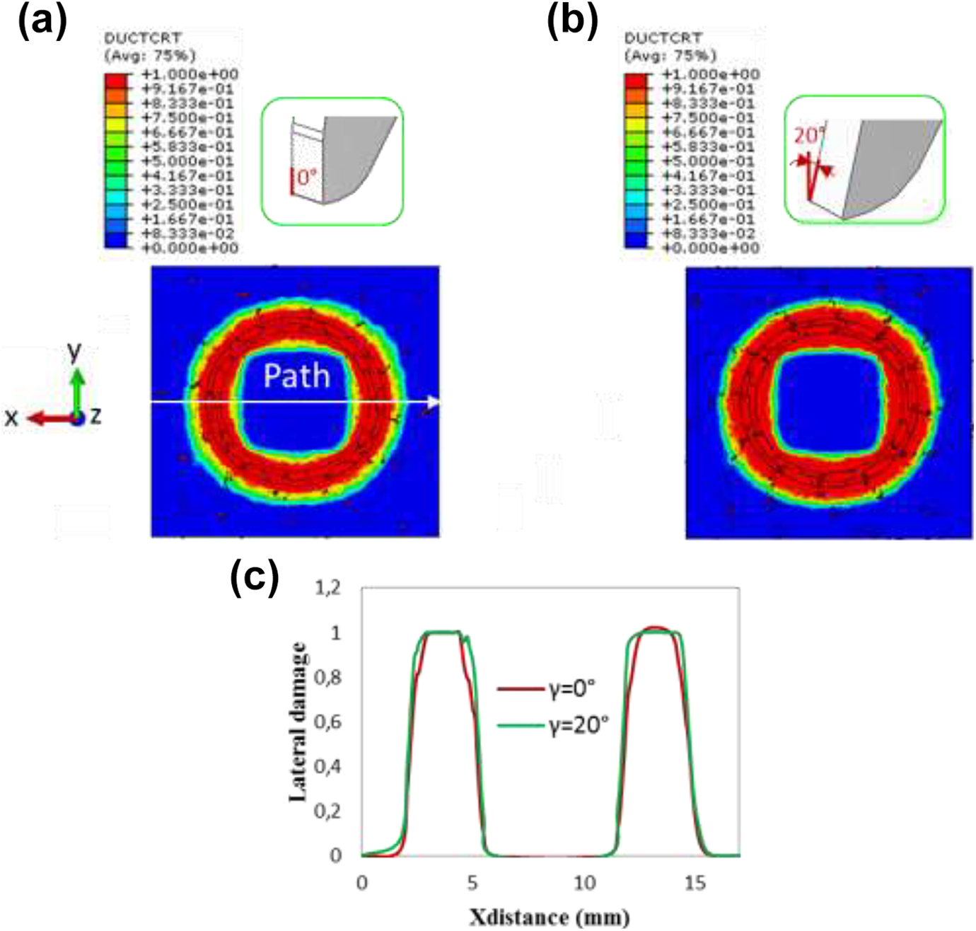
(a, b) Damage distribution in workpiece for 0° and 20° rake angle, respectively and (c) lateral damage along path.
As reported in the literature,42–44 the temperature has a considerable influences on the properties of materials as well as the drilling process. Wang et al. 44 revealed that the tensile strength and the elastic modulus of the composite decreased with the increase in temperature. Xu et al. 45 revealed that the temperature-induced damage is produced by the heat generation on the hole surface when drilling the composite material. Thus, it is important to investigate the effect of temperature on the plastic deformation and the drilling process, which will be the aim of some future work.
Figure 7 shows the depth of subsurface damage as well as the stress distribution in the workpiece as a function of the rake angle. It is observed that the ductile damage distribution, for a cross section of Figure 7(a) through the path shown in Figure 7(b), is wider for a rake angle of 20° than 0° (Figure 7(c)). This is explained by the increase in the stress concentration under the tool cutting edge (Figure 7(d) and (e)), which induces more damage. In fact, at the beginning of Figure 8(e) the Von mises stress value is about 700 MPa for a rake angle of 20°, but it is 650 MPa for a rake angle of 0°. However, it should be noted that the variation in damage is not very significant, as the difference of damage in the feed direction between the two angles is approximately 12%.
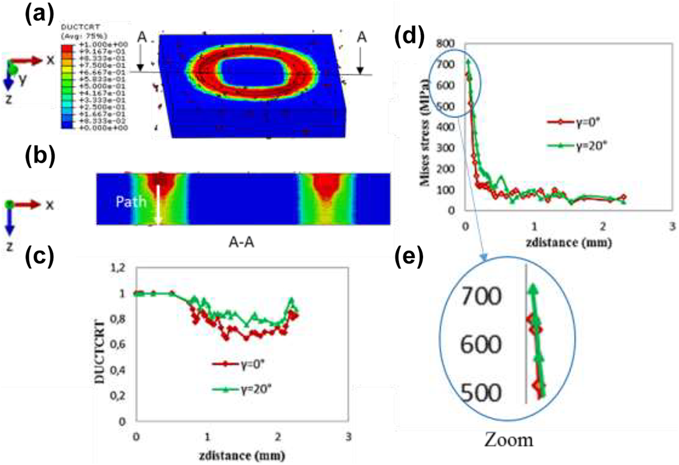
(a) 3D views of damage in the workpiece, (b) subsurface damage distribution in a cross section for penetration depth of tool of 0.75 mm and 0° rake angle, (c, d) damage and Mises stress versus zdistance for different rake angles and (e) zoom at start of (d).
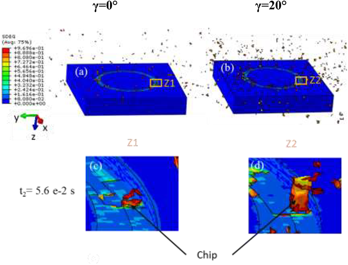
Material removal analysis for different rake angles: (a, b) 3D views and (c, d) zoom of the Z1 and Z2.
Material removal analysis
The numerical scalar stiffness degradation variable (SDEG) as well as the chip formation mechanism in the workpiece, for different rake angles and cutting times, are shown in Figure 8. When the variable SDEG reaches its maximum value 0.97, the material ahead the tooth was removed from the workpiece and the chip will be evacuated far from the cutting target. It can be seen in Figure 8(a) and (b) that the quantity of the material removed by a 0° rake angle is low compared to that of 20°. This result is due to the more important compression of material induced by a 0° rake angle, which induces more element deletion. Moreover, it is clear from Figure 8(c) and (d), which represent the zoom of the same tooth position (Z1, Z2) that the chip length ahead the tool grows as the rake angle is varied from 0° to 20°. Such an evolution is explained by the high shear stress applied by the sharp tool, which facilitates the chip flow on the tool rake face. It should be noted that a high rake angle leaves a better surface quality since it assists the chip to flow away from the workpiece. Such conclusion is in accordance with the literature. 46 Nevertheless, it is worth noting that a large rake angle reduces the tool life. 47 It is clear that fragmented chips are formed during the drilling process whatever the rake angle, which is mainly due to the fragile breaking mechanism of composite material. The same phenomenon was observed by Venu Gopala Rao et al. 48 during the machining of CFRP using a scanning electron microscopy. Moreover, The authors in ref. 49 mentioned that milling the SMC composites generate the formation of chips in the form of dust. Caprino and Santo 50 found that discontinuous chips were formed during the orthogonal cutting of SMC composites and they showed that the length of chips strongly depended on the depth of cut.
Conclusion
This paper proposes a new tool design for drilling the SMC composite using a hole saw tool. The aim of this work is to investigate the effect of tool geometry (rake angle) on the thrust force, the torque, the material removal process and the hole quality. For this purpose, the 3D FE model of drilling was developed using Abaqus/explicit software. The SMC composite is assumed to be an isotropic elastoplastic material. The Johnson Cook and the ductile damage criteria have been used to model the material behavior.
The conclusions that can be drawn from the present study are as follows: The proposed 3D FE model has been found very beneficial for modeling the drilling process using the hole saw tool. Reasonable accuracy between the numerical and experimental results has been observed with a difference of about 2% for the thrust force, 2.4% for the torque and 3% for the damage around the hole. The thrust force shows high dependency on the rake angle. It is well known that the thrust force tends to decrease by about 61% by increasing the rake angle from 0° to 20°. In contrast, this parameter has a non-significant effect on the torque. The difference of damage around the hole and in the feed direction is trivial when the rake angle is varied from 0° to 20°. The rake angle has a considerable effect on the material removal process. It can be concluded that increasing the rake angle leads to widening the chip length and facilitating its flow over the tool rake face.
It is recommended to enlarge the rake angle to reduce the thrust force when drilling the SMC composite. This parameter should be fixed with precaution because it affects the tool life.