
Abstract
The complex movement of artificial joints is closely related to the wear mechanism of the prosthesis material, especially for the polymer prosthesis, which is sensitive to motion paths. In this paper, the “soft-soft” all-polymer of XLPE/PEEK are selected to study the influence of motion paths on the friction and wear performance. Based on the periodic characteristics of friction coefficient and wear morphology, this paper reveals the friction and wear mechanism of XLPE/peek under multi-directional motion path, and obtains the quantitative relationship between friction coefficient and the aspect ratios of “∞”-shape motion path, which is of great significance to reveal and analyze the wear mechanism of “soft” all-polymer under multi-directional motion path. The results show that the friction coefficient is affected by the motion paths and have periodicity. Morever, under the multi-directional motion paths, the wear of PEEK are mainly abrasive wear and adhesive wear due to the cross shear effect, while the wear of XLPE is mainly abrasive wear with plastic accumulation. In addition, the friction coefficient is greatly affected the aspect ratios Rs-l of “∞”-shape and loads. Meanwhile, the wear morphologies are greatly affected by the aspect ratios Rs-l of “∞”-shape, but less affected by loads.
Introduction
With the aging of the population, the incidence of hip arthritis is increasing year by year, which affects people’s normal life. As the most effective method to treat hip arthritis, hip replacement has attracted more and more attention. At present, hip prosthetic materials (femoral head and acetabulum) are mainly divided into two categories: “hard-hard” (metal-metal, ceramic-ceramic) and “hard-soft” (metal-polymer, ceramic-polymer). However, in the course of service, metal-based materials will induce complications such as poisoning, allergy, pseudotumor and so on due to the release of metal ions,1–3 and ceramic-based materials will be fragile easily and produce abnormal sounds,4,5 which restrict the life of “hard” prosthesis materials. so the development of “soft-soft” prosthesis materials combination has great prospects.
“Soft-soft” prosthesis material combination can not only avoid the above problems, but also has the advantages of low modulus of elasticity, low density and easy to manufacture and moulding.6,7 The all-polymer prosthesis has been proposed for a long-time, especially for knees and fingers, which effectively reduces the weight burden of patients and the risk of metal ions release. In 1991, the silane crosslinked polyethylene finger joint was proposed to be proved with very low wear rate on joint simulators. 8 The results of total polymer knee arthroplasty with polyacetal as femoral and ultra-high molecular weight polyethylene (UHMWPE) as tibial were encouraging. The survival rate of polymer prosthesis was 77% which was similar to 86% of traditional CoCrMo component. 9 The study of total polymer hip arthroplasty showed that poly-ether-ether-ketone (PEEK) and high crosslinked polyethylene (XLPE) showed a low wear rate, 10 and the results of CF-PEEK and high crosslinked polyethylene were good, but the clinical results were uneven.11–13 PEEK has attracted more and more attention as prosthesis materials which are expected to replace metal femoral head due to their relatively low manufacturing cost, good biocompatibility, excellent heat resistance, corrosion resistance, insulation, excellent wear resistance and fatigue resistance.14,15 XLPE, as a new generation of acetabular prosthesis material, has higher wear resistance. Thus, the “soft-soft” total hip prosthesis of PEEK and XLPE is an ideal choice, but its wear resistance needs to be confirmed.
Some researchers believe that the wear performance of semi-crystalline polymer prosthesis materials should be measured under multi-directional stress field rather than unidirectional motion,16,17 because the kinematics of artificial joints shows that the movement and stress of hip joint and knee joint are multi-directional, especially the hip joint supporting the main movement of lower limbs, which is mainly subjected to complex motions of three vector planes: flexion and extension, adduction and extension, and internal and external rotation under normal gait movement. By tracing the marker points on the femoral head and the acetabular cup by different hip simulators and computer simulation, they were found that the sliding trajectories on the femoral head are mainly elliptical and 8-shaped, 18 and which on the acetabular cup are mainly 8-shaped, straight-line, asymmetric ellipse and ellipsoid. 19 The wear trajectories at different positions are different in shape. The motion of hip joint is multi-directional rather than simple linear motion, so the evaluation of hip prosthesis materials, especially polymer materials, should also be carried out under multi-directional motion paths. UHMWPE, as the most widely used material for acetabulum of hip joint, has been widely proved that its wear performance is closely related to the motion path. It is sensitive to different motion paths,20–22 and the experimental results under multi-direction motion are closer to the clinical observation results. The effects of cross-shear stress on the wear of UHMWPE and XLPE were studied under different aspect ratios of rectangular sliding trajectories. The results showed that the shear stress of different trajectories had significant effects on UHMWPE, but had no significant effect on XLPE. 23 The wear rate of PEEK increases with multidirectional sliding. 24 Baykal systematically studied the friction and wear properties of 20 different pairs under elliptical motion paths, showed that the total polymer pairs exhibited a lower wear rate, 25 which provided some theoretical support for the clinical application of the total polymer material.
Although many scholars have studied the friction and wear of hip prosthesis materials under multi-directional motion, they mainly focus on the overall wear of materials under different wear trajectories of femoral head and mainly focus on the “hard-soft” pairs. However, there are few reports on the systematic study of wear process of “soft-soft” all-polymer prosthesis under different wear locations and different wear trajectories of acetabulum. The wear mechanism of “soft-soft” all-polymer prosthesis is still unclear. In this paper, XLPE and PEEK are selected as all-polymer friction pairs to study the effect of different motion paths on the friction and wear and the wear process. The evolution of friction coefficient under different motion paths and the effect of different paths on the wear morphology and mechanism of the pairs are analyzed. The effects of the aspect ratio of the motion paths and the loads on the friction and wear of the prosthetic materials under the “∞”-shaped motion path are emphatically studied, which can provide some theoretical support for the design of all-polymer prosthesis materials in clinical application.
Materials and methods
Samples
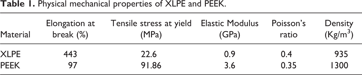
XLPE and PEEK were selected as pin and disc. Based on the hip joint structure and motion model, the ball-disk contact model was simplified as shown in Figure 1. XLPE (Transjun Plastic Trading Co., Ltd., Shanghai, Molecular weight: 3 million) was processed into a ϕ 40 * 4 mm disc, and then polished to a surface roughness of less than 0.2 um to meet the requirements of the surface roughness of the acetabulum cup. The PEEK pin, size of ϕ6 * 10 * ϕ10 mm, is provided by O’Connor Medical Technology Development Co., Ltd. (Injection molding, particle diameter 13μm). The surface roughness of the pin is less than 0.1 um, which meets the joint surface requirements of the metal femoral of the artificial hip prosthesis. The mechanical properties of the XLPE and PEEK are shown in Table 1. The geometries of the samples are shown in Figure 2.
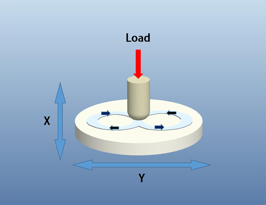
Simplified motion model.
Physical mechanical properties of XLPE and PEEK.
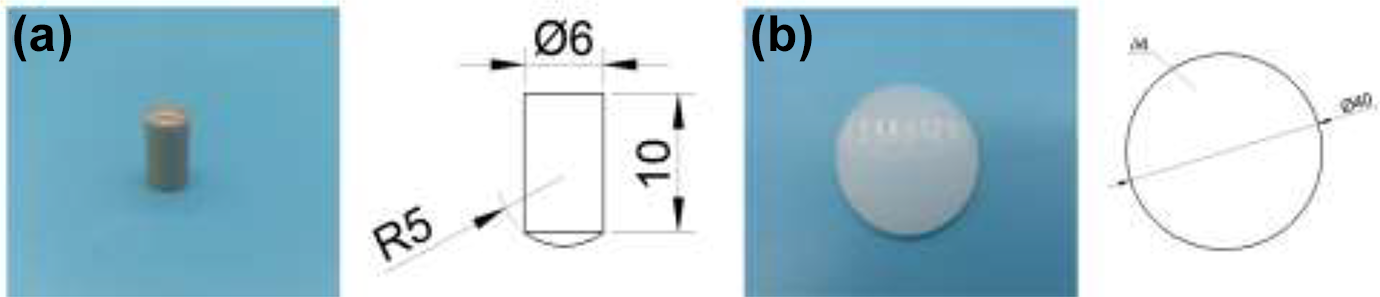
The geometries of the samples: (a) PEEK pin, (b) XLPE disc.
Before testing, the samples should be washed with alcohol and distilled water for 0.5 hours and then immersed in 25% calf serum solution diluted with distilled water (Sijiqing Bioengineering Materials Co., Ltd, Protein concentration 38g/L) for 2 weeks to stabilize the absorption of the liquid. Then the immersed samples stored in a sealed, dustless container with temperature of 37°C and relative humidity of 45% for 48 h to stabilize their weight. Sample quality was measured with a high-precision digital balance with resolution of 0.01 mg, and then the samples were put into the fixed device.
Wear testing
The friction and wear tests of multi-directional motion paths were carried out on a self-made testing machine. As shown in Figure 3, the tester consists of four parts: normal loading module, two-dimensional platform, temperature module and software control module. The normal loading module is equipped with a 200 N three-dimensional force sensor with an accuracy of 0.1% F.S. The two-dimensional platform is driven by X and Y two-way servo motors to ensure the smooth operation of the multi-directional paths. The movement between acetabulum and femoral head of human hip joint is complex. It can be carried out in three degrees of freedom: extension/flexion (FE), adduction/abduction (AA) and internal/external rotation (IER). The wear track is irregular and shows a multi-directional wear track. Therefore, the motion paths of circular, elliptical, “∞”-shape and reciprocating line are selected for friction and wear experiments to explore the influence of motion paths on the friction and wear behavior of prosthesis materials. In addition, the effects of load and aspect ratio R s-l (defined as the short-axis of ellipse (s) divided by the long-axis of ellipse (l)) on friction and wear of materials under “∞”-shape motion paths are explored. The experimental schemes are shown in Tables 2 to 4 (n = 3).
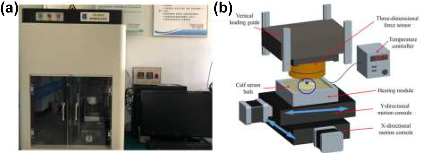
The multi-directional motion path friction testing device.
Effect of motion paths on the friction and wear of PEEK/XLPE.
Effect of
Effect of load on friction and wear of PEEK/XLPE under”∞”-shape motion paths.
Sliding speed and normal loads were determined according to the dynamic analysis of artificial hip joint 26 and the range of motion velocity between acetabulum and femoral head. 27 25% calf serum solution was selected as lubricant to simulate wear environment in vivo. The sliding distance is 25 mm.
Post-test data analysis
After testing, the samples were washed in alcohol and distilled water for 0.5 h, then stored in a sealed, dustless container with temperature of 37°C and relative humidity of 45% for 48 h to stabilize their weight.
In order to analyze the friction mechanism, the average friction coefficient was obtained from the time-varying friction coefficient data of the last 5 min, and the variation of single-period friction coefficient was discussed. The optical morphology, three-dimensional morphology and scanning electron microscopy photographs of XLPE and PEEK were tested to explore the wear mechanism of PEEK/XLPE under different motion paths and the effects of aspect ratio and loads on multidirectional friction and wear.
Results and discussion
Tribological characteristics under different motion paths
Coefficient of friction
Figure 4 shows the variation of friction coefficients of PEEK/XLPE under different motion paths. From the time-varying curve of friction coefficients of Figure 4(a), it can be seen that the friction coefficients of reciprocating line and “∞”-shape paths can be divided into three stages: sharp rising, slow declining and stabilization, while those of elliptic and circular paths can be divided into four stages: sharp rising, sharp declining, slow increasing and stabilization. The time and variation of curves at each stage are different under different motion paths. When the path is reciprocating line, the time required for rising sharply is longer (700 cycles). When the paths are multi-directional shapes (circular, elliptical or “∞”- shape), the rising period of curve is shorter (100–150 cycles). There are also many difference among them, such as, the rising period of “∞” shape path has the sharpest change and the largest peak value, the curve of circular path rises slowest with the longest time, and the curve of elliptic path rises sharply with the shortest time and the smallest peak value. In the initial stage of wear, there is mechanical interlocking between the contact surfaces of friction pairs due to the micro-convex body, which makes a big friction resistance and a sharply rising friction coefficient. Under the multi-directional motion paths, friction pairs move in various directions, resulting in increased resistance and cross-shear. Therefore, the friction coefficient curve rises faster in the early stage and has a shorter period.
With the wear times increasing, the micro-convex bodies were gradually flattened and the mechanical interlocking phenomenon disappeared, as a result, the actual contact area increased, the contact stress decreased, and the friction coefficient entered a slow decline period. Under the reciprocating line motion path, the decline period of friction coefficient is the most gentle with a small decrease range. It reaches a stable level at about 1200 cycles with a stable friction coefficient of 0.124. Under the “∞”-shape motion path, the curve descends most dramatically with a largest descent range. It enters the stable period about 1000 cycles with a stable friction coefficient of 0.1. This is because the “∞”-shape path is the most complex with the largest direction change frequency, and the cross shear and material coordination are the most obvious. The friction coefficient under circular and elliptical paths end at about 550 cycles. At this time, the plastic deformation recovery of the material is not enough to offset the increase of friction resistance due to multi-directional shear. It enters a slow upper stage, and the material itself reconciles the friction resistance, and then enters a stable stage at 1400 cycles. Figure 4(b) shows the average friction coefficient of the stable period by the friction coefficient of the last 5 min. The stable friction coefficient decreases with the increase of the complexity of the motion paths, except for the reciprocating line, as follows: linear friction coefficient > circular friction coefficient > elliptical friction coefficient > “∞”-shape friction coefficient.
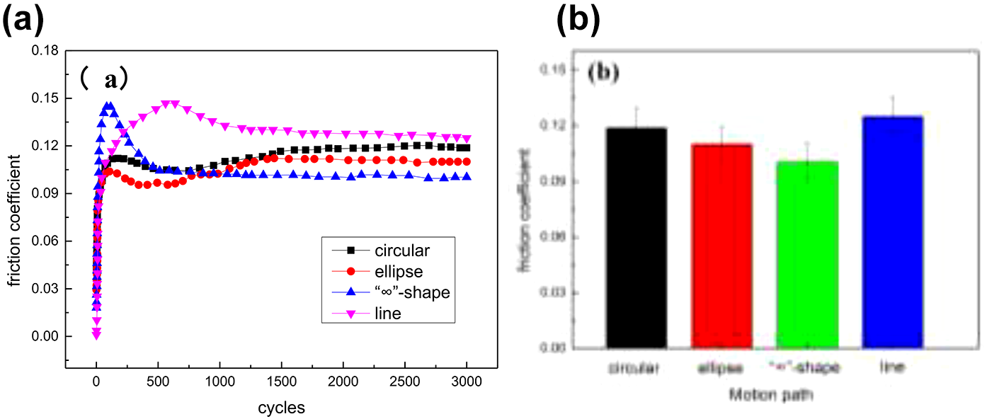
Friction coefficient under different motion paths.
Wear morphology
Figure 5 shows the wear morphologies of the PEEK surface under different motion paths. It can be seen from the optical morphologies that there are intersectional scratches on the PEEK surface in many directions under the multi-directional motion paths. The number of scratches of center wear area is less, and those of the edge wear area is larger. However, under the linear path, the wear morphologies show some deeper, uniform-distribution and parallel linear scratches, due to the single shear direction and the concentration of stress. Scanning electron microscopy (SEM) shows that the interlacing of scratches in the wear center increases with the path complexity, accompanied by plastic accumulation, while the wear in the edge region is mainly characterized by arc-shaped interlaced scratches, tearing and lamellar exfoliation. The reasons for this are plastic deformation and cross scratches first occur in the central area of PEEK surface, forming micro-debris, and then forming three-body wear, under the action of cyclic contact stress. Meanwhile, as wear continues, the contact area of friction pairs increases, and the small particles from the central area move to the edge area under the scouring effect of calf serum lubricant, furthermore, the micro-particles cut the specimen with the cross-shear action, forming grooves, tearing and peeling. Under linear path, the wear of center area are mostly parallel scratches and scaly tears perpendicular to the scratch direction, while that of edge area are deep furrows and larger scaly tears. Under the more complex motion path, with greater change rate of direction, the actual contact area of the friction pairs increases, the coordination effect of plastic deformation becomes obvious, the local contact stress and the friction shear effect decrease, and then the wear is slight. Therefore, the wear of linear path is more serious than that of multi-directional motion paths, and the wear of “∞”-shape motion path is the slightest.
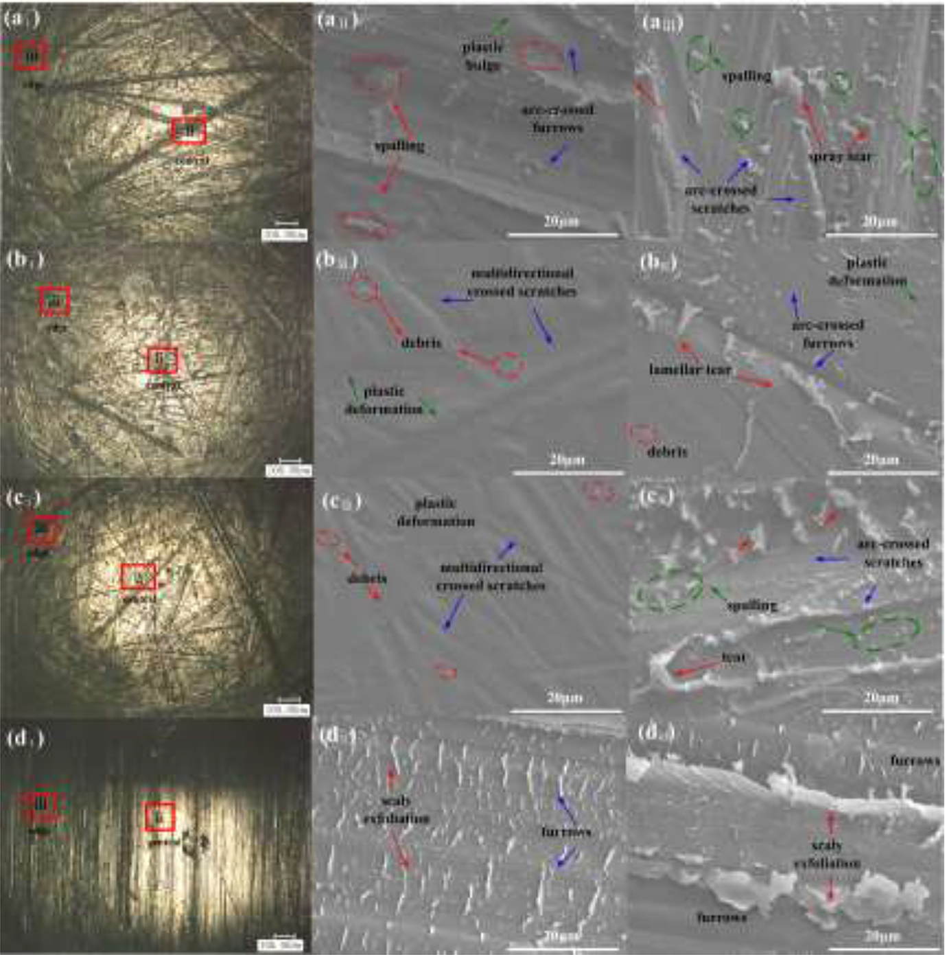
Worn morphologies of PEEK under different motion paths.
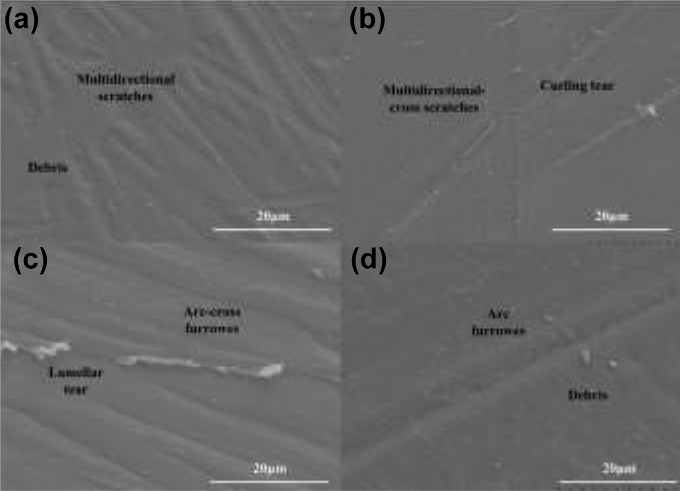
Figure 6 shows the SEM surface morphologies of XLPE under different motion paths. Under multi-directional motion paths, the surface of XLPE shows arc-shaped scratches, in which the deepest scratches are made under circular path, accompanied by tearing and peeling debris on the inner side of the scratches. Under elliptic path, the scratches are smaller, accompanied by micro-wrinkles and a small amount of small particle debris. Under “∞”-shape path, the surface scratches are shallow and dense. Besides, under the linear path, the Parallel linear scratches are uniformly distributed with high density and some deep scratches are accompanied by curling burrs. This is mainly because the radial force is the same in the circular motion track, the deepest scratch is produced on the XLPE surface, while the centripetal force in the ellipse and “∞” shape track is different in size and direction, and the surface scratch of XLPE is shallow.
Worn morphologies of XLPE under different motion paths.
Figure 7 shows the three-dimensional morphologies and wear depth and width of XLPE worn surface under different motion paths. The wear profile shows a “U” shape, with low wear and no obvious material loss. The outer area of the edge is slightly higher than the matrix, with some micro-convex. Comparing with the color scale, it can be seen that under the circular path, the wear is the most serious, followed by that of straight line, and that of “∞”-shape is the shallowest. At the bottom of the line path wear profile, straight-line furrows can be clearly seen, which is consistent with the results in Figure 6. It can be seen from the wear depth and width of the wear profile under different motion paths in Figure 7(e) that the wear depth and wear width decrease with the complexity of the motion paths under the multi-directional paths, while the wear depth under the linear path is 26.69 µm as compared with that of the circle, but the wear width is smaller, which is 1.7 mm as compared with that of “∞”-shape.
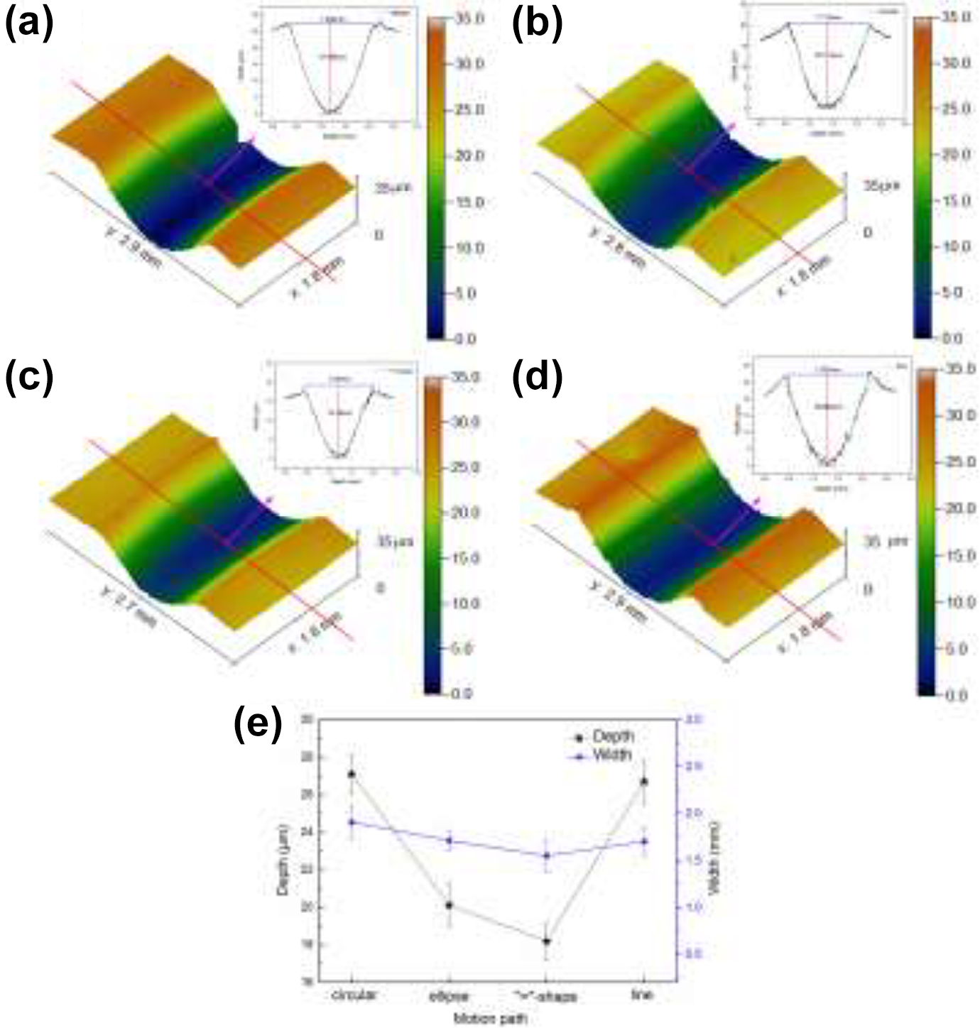
Worn profiles of XLPE under different motion paths
Multidirectional friction and wear
In different aspect ratios
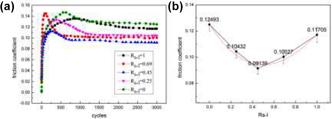
Figure 8 shows the friction coefficient of PEEK/XLPE of different aspect ratios Rs-l under “∞”-shape motion path. From the time-varying friction coefficient (Figure 8(a)), it can be found that the friction coefficient of PEEK/XLPE of different aspect ratios Rs-l (When the path is a reciprocating line, which is infinitely stretched “∞”-shape, the Rs-l is 0,) increase sharply, decrease slowly, and then gradually stabilized. From the stable friction coefficient (Figure 8(b)), it can be seen that the friction coefficient decreases first and then increases with the increase of Rs-l value. The results show that the aspect ratios Rs-l has an important influence on the friction and wear of materials, which is consistent with Dunn ‘s spatial geometry effect friction and wear model-the change of curvature radius has a significant effect on the friction and wear of materials.
28
The relationship between the aspect ratios Rs-l and the friction coefficient was fitted and found that the relationship of friction coefficient and Rs-l value is consistent with the univariate cubic equation:
The friction coefficient is closely related to the aspect ratios Rs-l of “∞”-shape path. When Rs-l value approaches 0.5, the friction coefficient reaches the minimum value about 0.09. When Rs-l value approaches 0 or 1, the motion path is reciprocating line or double-circle, with small changes in curvature and direction of motion, under which path, the direction of shear stress of friction pairs, especially the PEEK, changes little, making directional softening of material surface, Furthemore, the wear surface was damaged, then the friction coefficient is large about 0.12. When 0 < Rs-l < 1, with the Rs-l increasing, the “∞”-shape path is gradually flattened, along with the radius of curvature range increasing, the change rate of curvature and velocity direction raising. At this time, the material surface is subject to multi-directional wear, without concentrated damage, and the material structure is stretched or compressed in multiple directions with plastic recovery to resist wear. When the repair ability of the material is greater than the shear force. The friction coefficient decreases (0 < Rs-l < 0.5), but when the those recovery ability is insufficient to offset the shear force, the friction coefficient increases (0.5 < Rs-l < 1).
Friction coefficient under different Rs-l under “∞”-shape motion path.
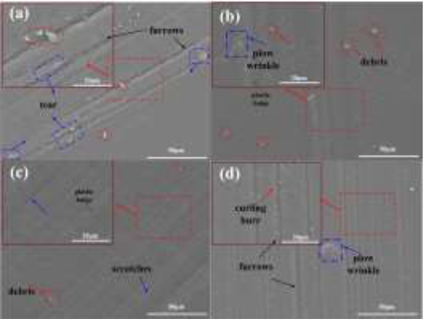
Compared with Figures 5 and 6, it is found that the wear of PEEK pin is more serious than that of XLPE disc under multidirectional motion paths. Then, the wear of PEEK surface is mainly studied in this part. Figure 9 shows the wear morphologies of PEEK surface in different Rs-l under “∞”-shape motion path. When Rs-l = 0.69, there are mostly multidirectional scratches and small amount of debris. When Rs-l = 0, the motion path is the reciprocating line, the surface wear is the most serious with many parallel furrows, on both sides of which there are curling tears and scale tears. When Rs-l = 1, the motion path is the double-circle, the wear of PEEK is only superior to that of Rs-l = 0, with crossing scratches and serious curl tears. When Rs-l = 0.45, in addition to multidirectional scratches, there are lamellar accumulation and a few of tearing spalling on the surface of PEEK. When Rs-l = 0.25, the motion path is a flattened “∞” shape with large range and small change rate of large curvature. On the surface of PEEK, it shows a decrease in the intersection of scratches or furrows, but the tearing forms are diversified, such as lamellar tearing, scale tearing, long strip tearing, etc.
Above all, he damage of PEEK surface increases with the Rs-l value, first decreases and then increases. This is because as the Rs-l increases from 0 to 1, the curvature radius range of the motion path decreases, the ratio of the large curvature radius decreases, and the change rate of the sliding direction increases within the unit distance. However, under the multi-directional motion paths, the cross shear effect of PEEK is obvious, because the cross shear angle is closely related to the direction of real-time sliding velocity and the composition of materials. Therefore, under the synergistic effect of cross shear effect and plastic recovery, the damage of PEEK shows the above rules.
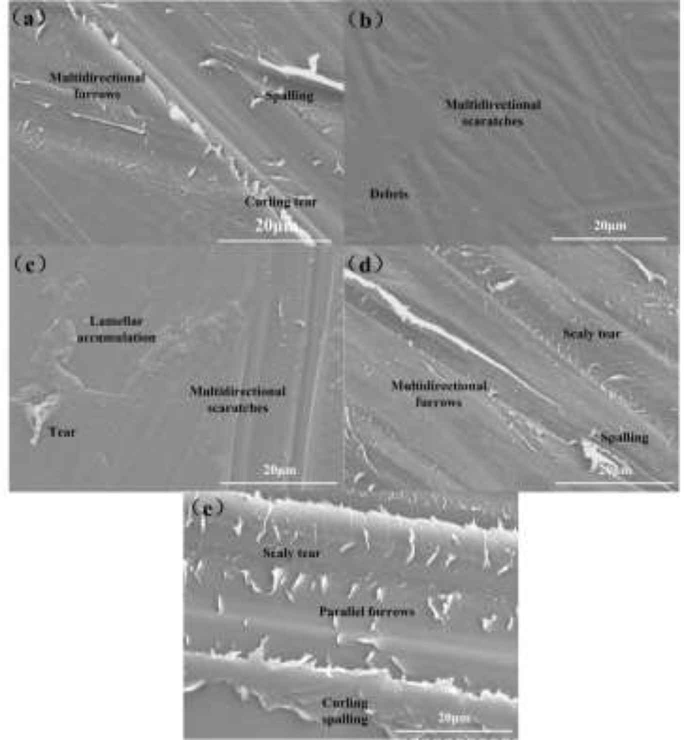
Worn morphologies of PEEK in different aspect ratios Rs-l under “∞”-shape motion path.
On different loads
The influence of the load of the prosthesis material is obvious under reciprocating line motion path, but under multidirectional motion paths, whether the friction and wear of the prosthesis material are also affected by the load and whether they have the same law are not known. Therefore, this paper studies the response of the load to the friction and wear of the prosthesis material under the multi-directional “∞”-shape path. Figure 10 shows the friction coefficient under different load under “∞”-shape motion path. From the time-varying friction coefficient (Figure 10(a)), it can be seen that the smaller the load is, the steeper the rising and falling stages are, and the longer the time required to enter the stability period is. When the tests begin, a large number of micro-convex bodies and micro pits on the specimen surface contact with each other and become deformation. The higher convex peaks with larger elastic deformation are flattened, and the lower micro pits with little elastic deformation form new micro peaks under cutting and extrusion. When the load is small, the elastic deformation of the material is weak, which is seriously affected by the micro-convex bodies and micro pits, and the friction coefficient fluctuates greatly. However, when the load is large, the cutting effect of the load on the micro-convex bodies on the material surface increases, and it will enter the stable stage earlier.
From the average friction coefficient in stable period (Figure 10(b)), it can be seen that the friction coefficient decreases with the increase of load, which is consistent with the friction and wear law of natural articular cartilage materials. 29 The friction coefficient is mainly affected by the actual contact area. On the one hand, with the increase of normal load, the contact radius and surface deformation depth between the friction pairs will increase, and then the actual contact area between PEEK and XLPE will increase and the stress concentration will decrease. On the other hand, under the large load, the surface roughness of the material will decrease due to deformation, which will make the friction shear force decrease, and a low friction coefficient.
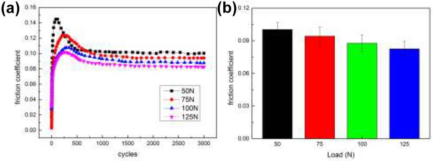
Friction coefficient under different load under “∞”-shape motion path.
It can be seen from the wear morphologies of PEEK in different load under “∞”-shape motion path (Figure 11) that the damage mechanisms of PEEK are mainly plastic deformation and abrasive wear, and with the increase of load, abrasive wear increases, accounting for the dominant mechanism. When the normal load is 50 N, the plastic deformation of PEEK is obvious with long ridges in different directions due to the multidirectional shear. As the test proceeds, the lubrication film of PEEK is damaged and forms staggered scratches with wear debris at the bottom of them. The heat generated in the friction process increases with the increase of the load, and then the temperature of the local contact area increases, result in the acceleration of the damage of lubricating film, the increasing of scratch depth form furrows, and the intensified abrasive wear. When the normal load is 75 N, there are bigger scratchs on PEEK surface with flaky curl tear both sides of them. When the normal load is 100 N, the arc-shaped furrows of PEEK surface are obvious and accompanied by layered plastic accumulation, and there are spray tear and tear debris at the intersection of the furrow, which caused by the cross shear effect and adhesion between the contact interfaces. When the normal load is 125 N, the contact stress increasing, there are some deeper furrows on the PEEK surface with small adhesive flakes at the bottom and block debris on the outside. This is mainly due to the initiation and propagation of the crack source at the internal defects of the substrate surface, resulting in stress concentration in the local area under the large load, high speed change rate, and long-time reciprocating motion, the bonding weak area of the substrate material is separated from the substrate, forming wear debris.
Worn morphologies of PEEK in different load under “∞”-shape motion path.
Friction and wear mechanism
“Soft-soft” prosthesis material combination of PEEK and XLPE is an ideal choice for hip joint prosthesis. PEEK and XLPE both are semi-crystalline thermoplastic polymer, which are greatly affected by wear path. Relevant researchers have shown that the wear performance of semi-crystalline polymer should be measured by multi-directional stress field rather than single stress field.16,17 Thus, it is necessary to evaluate the wear performance of PEEK/XLPE under various motion paths. According to the worn morphologies of PEEK (Figure 5 and XLPE (Figure 6) under different motion paths, the wear forms of PEEK are mainly staggered scratches and lamellar tears, and the damage forms of XLPE are mainly ploughing and plastic deformation. Totally speaking, The wear of PEEK is more serious than that of XLPE. Ge 30 used Si3N4 ball sliding on the UHMWPE disc under multidirectional motion path, the surface wear of UHMWPE mainly showed multidirectional scratches and a large number of lamellar tearing and peeling. Song 31 used PEEK and UHMWPE to carry out the cervical joint wear test. The results showed that the wear of PEEK was mainly straight-line plough groove and crack, and the wear of UHMWPE was mainly straight-line plough groove and adhesion. It can be concluded that the wear mechanism is closely related to the structure and sliding form of the friction pairs.
The friction coefficient of different multidirectional motion paths is different, which shows that it decreases with the increase of the complexity of the motion path, and it has distinct periodic rule, which is mainly related to the structure of PEEK and XLPE. PEEK is a kind of semi crystal polymer with linear ordered and amorphous two-phase microstructure. In addition, the molecular chain will change under the external deformation, thermal energy, vibration or rotation. 32 XLPE, a semi-crystalline thermoplastic material with the three-dimensional network structure, that is, the isotropic crystalline layer connects the entangled layer structure through the anisotropic molecular chain, 33 is sensitive to shear force and sliding direction. Under different specific motion path, the material has different stress coordination feedback, so it shows different friction coefficient and periodic law.
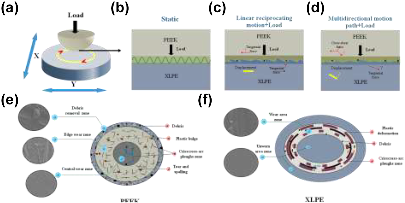
Figure 12 shows the wear mechanism of PEEK/XLPE. The wear of XLPE is mainly affected by the surface roughness, load, sliding speed and the pair materials. 20 Under the static loading, the friction pairs are mainly subject to the normal load for plastic deformation, affected by the load and surface roughness, as shown in Figure 12(b). Under the normal load and linear reciprocating motion. The materials mainly have the normal force and tangential force (the direction is parallel to the sliding direction and single), as shown in Figure 12(c), which is also mainly affected by the load and surface roughness. Under the normal load and multi-directional motion, according to the motion mode (Figure 12(a)), during the testing, PEEK is mainly affected by the normal load and cross shear force with cross shear effect. While the XLPE is mainly affected by the normal load and the shear force (the direction changes with the position of the motion track), as shown in Figure 12(d), and its tribological properties are mainly affected by the shear force and relative velocity, which determined by the motion paths.
Wear mechanism of PEEK/XLPE.
The wear of PEEK is more serious than that of XLPE under different motion paths. This is because in the process of wear, the plastic deformation, cross scratch and micro tearing debris are formed in the center area of PEEK first, due to the cyclic cross shear stress. Then, the debris move around under the centripetal force and lubricating fluid, and then three-body abrasion is formed in the edge area of PEEK. As a result that the edge area wear increases with more Crossed and deeper scratches, even the material tears and peels off, as shown in Figure 12(e). As the direction of shear force changes with the wear path, the wear of XLPE is shown as circular scratches parallel to the motion path. Furthermore, because XLPE is relatively softer than PEEK, the micro bulges on the XLPE surface are easier to be cut to form a flat surface. At the same time, those micro grinding debris, forming three-body wear, cut the surface as a circular pear groove, as shown in Figure 12(f).
Under the multi-directional motion paths, the aspect ratios Rs-l of the motion path also has an important influence on the wear and friction of pairs, which is mainly related to the direction and relative change rate of curvature radius and relative sliding speed. The coordination response of the material structure to different motionpaths is different, which is shown that with the increase of the relative change rate of curvature radius, the angular velocity change is accelerated, leading to the faster fluid flow. In addition, the cross shear effect and dissipation of heat self-recovery and debris particles are enhanced, which make the material have stronger self-recovery ability. But when the material damage exceeds the self-recovery coordination range, the wear will become more serious.
Conclusion
The “soft soft” polymer of XLPE/PEEK is sensitive to the motion paths. The results show that the friction coefficient and wear morphology have obvious periodic characteristics. In the multi-directional motion path, the wear of PEEK is mainly abrasive wear and adhesive wear caused by shear effect, while the wear of cross-linked polyethylene is mainly abrasive wear with plastic accumulation. In addition, the relationship between friction coefficient and aspect ratio Rs-l has a cubic equation:
Footnotes
Funding
The author(s) disclosed receipt of the following financial support for the research, authorship, and/or publication of this article: This research is supported by National Natural Science Foundation of China (Grant No.51875564, 51705517), 333 High-level Talents Training Project of Jiangsu Province (Grant No. BRA2019063) and A Project Funded by the Priority Academic Program Development of Jiangsu Higher Education Institutions (PAPD).