
Abstract
Nano-CeO2–reinforced NiCoCrAlY coatings were fabricated on Ti6Al4V alloy using laser cladding. The morphologies, chemical compositions, and phases of obtained coatings were analyzed using a scanning electron microscope, energy-dispersive spectrometer, and X-ray diffraction, respectively, and the effects of nano-CeO2 mass fraction on the coefficient of friction and the wear rate of NiCoCrAlY coating at 600 °C were investigated using a ball-on-disk wear test. The results show that the nano-CeO2–reinforced NiCoCrAlY coating is mainly composed of NiTi2, Ti3O, CoO, and β-Ti phases, while the new phases of AlTi3 and (Ni, Co)2Ti4O are formed after the wear test. The average coefficients of friction of NiCoCrAlY coatings with the nano-CeO2 mass fractions of 0%, 2%, 4%, and 6% are 0.699, 0.655, 0.636, and 0.615, respectively, and the corresponding wear rates are 4.04 × 10⁻⁷, 3.95 × 10⁻⁷, 3.13 × 10⁻⁷, and 2.35 × 10⁻⁷ mm3 N−1 m−1, respectively, which decrease with the increase of nano-CeO2 mass fraction. The wear mechanism is primary adhesive wear and oxidation wear, accompanied by slight abrasive wear, and the addition of nano-CeO2 is the main factor that is enhancing wear resistance.
Introduction
As a (α+β)-type structure, 1 Ti6Al4V alloy accounts for 50% of the total amount of titanium alloy, and its wear resistance is poor because of low hardness,2,3 which further limits its use under friction conditions. 4 As an excellent thermal barrier, MCrAlY (M = Ni, Co, or combination of these) coatings have been widely used at high temperatures to elevate the friction wear performance of Ti6Al4V alloys. 5 The addition of CeO2 improved the oxidation resistance of high-velocity oxygen fuel (HVOF)-sprayed MCrAlY coating; 6 especially, CeO2 in the nano form has the advantages of large specific surface area and high chemical activity and still retains the unique characteristics of rare-earth elements, 7 which is used as a reinforced phase to add into the NiCoCrAlY coating. 8 It has the advantage over traditional coatings at high temperatures because of their hardness and wear resistance.9–11
At present, thermal spraying is usually used to fabricate NiCoCrAlY coating, 12 and the irregular oxide layer grows on the coating surface, 13 which decreases its wear performance. As a new kind of coating technology, laser cladding (LC) prevents the formation of the oxide layer under the protection of Ar gas.14–16 Chun et al. 17 prepared the NiCoCrAlY/ZrB2 coating on the pure Ti substrate using an LC and found that the ZrB2 improved the wear resistance of the substrate at high temperatures; Hao et al. 18 investigated the wear resistance of NiCoCrAlYTa coating on the Inconel 718 substrate, which was improved by the post-oxidized to form the oxidative layer; Meng et al. 19 analyzed the laser-cladded NiCoCrAlY coating by adding Ni-based powder, which reduced its wear rate; Pereira et al. 20 prepared NiCoCrAlY and CoNiCrAlY coatings on AISI 304 steel by LC and found that the coefficients of friction (COFs) decreased with the increase of temperature; Mahesh et al. 21 investigated the oxidation behavior of NiCrAlY–CeO2 coating on the Ni-based substrate and revealed that the incorporation of CeO2 elevates its oxidation resistance; and Yanan et al. 22 investigated the effects of CeO2 on the microstructure and properties of TiC/Ti2Ni-reinforced Ti-based coating by LC and found that the grains were refined on the coating with the CeO2 mass fraction of 2%, while excess CeO2 hindered grain refinement, resulting in the decrease of wear resistance. The above-mentioned researches showed that the wear resistance of NiCoCrAlY coating was mainly used for the protection of Ni- and Fe-based substrates; however, the wear resistance of NiCoCrAlY coating by the addition of nano-CeO2 on the Ti6Al4V alloy has rarely been reported, which affects its friction wear performance and service life.
In this study, NiCoCrAlY coatings with the different nano-CeO2 mass fractions were fabricated on Ti6Al4V alloy using a LC. 23 The aim was to investigate the effects of nano-CeO2 mass fraction on the friction wear performance of obtained coatings, which provided an experimental basis for the wear resistance of nano-CeO2–reinforced NiCoCrAlY coating.
Experimental procedures
Sample preparations
The substrate was Ti6Al4V alloy with the following chemical composition (wt, %): Fe ≤ 0.30, C ≤ 0.10, N ≤ 0.05, H ≤ 0.015, O ≤ 0.20, Al 5.5–6.8, V 3.5–4.5, and Ti was balanced. The chemical composition of nano-CeO2 (wt, %) was as follows: CeO2 99.99, Ln2O3≤ 0.01, Nd2O3+ Pr6O11≤ 0.03, Fe2O3≤ 0.01, SiO2≤ 0.02, CaO ≤ 0.01, and Al2O3≤ 0.02; and that of NiCoCrAlY powder (wt, %) was as follows: Cr 20–22, Al 5, Fe ≤ 1, Y 0.5, Co 6, and C 0.4, and Ni was balanced. The laser-cladded NiCoCrAlY powders with the nano-CeO2 mass fractions of 2%, 4%, and 6% were milled using a planetary ball miller for 2 h. The morphologies and phases of nano-CeO2–reinforced NiCoCrAlY powders were analyzed using a JSM–6360LA type scanning electron microscope (SEM) and D/Max 2500/PC type X-ray diffraction (XRD), respectively.
The LC test was conducted on a ZKSX–2008 type fiber-coupled laser spraying system with the operation mode of continuous wave (CW). Technical parameters were as follows: laser wavelength of 1064 nm, beam distribution of circular Gaussian, spot diameter of 4 mm, laser power of 1400 W, scanning speed of 4 mm s−1, overlap rate of 50%, Ar gas speed of 8 L min−1, and powder feeding speed of 8 g min−1.
Characterization methods
The morphologies and phases of obtained coatings were analyzed using a JSM–6360LA type SEM and D/Max 2500/PC type XRD, respectively. The hardness was measured using a micro-Vickers hardness tester; test parameters were as follows: load of 5 N and pressure holding time of 10 s, and the hardness was characterized with the average value of three times.
The wear test was conducted on a HT–1000 type high temperature wear tester, and the COF and wear rate were the average value of three tests. Test parameters were as follows: friction mode of ball–disk contact, friction couple of a Si3N4 ceramic ball, temperature of 600 °C, wear load of 3 N, speed of 500 r min−1, and time of 30 min. The morphologies and chemical elements of worn tracks were analyzed using a JSM–6360LA type SEM and its configured energy-dispersive spectrometer, respectively; and the profiles of worn tracks were analyzed using a VHX–700F type ultra–depth microscope (UDM).
According to the contoured curve of the worn track, the wear area S is calculated by an Origin 8.5 software, and the wear volume was given as

where l is the length of worn track (mm) and S is the area of worn track (mm2). Wear rate was given as

where V is the wear volume/mm3; L is the wear distance/m; and p is the wear load/N. According to equations (1) and (2), the wear rate (Δ) was positively correlated with wear volume (V) and the wear area (S). The small wear area meant the low wear rate, that is, the wear resistance of coating was high.
Analysis and discussion
Morphologies and XRD analysis of powders
Figure 1(a) shows the morphology of NiCoCrAlY powder. The powders were spherical and cylindrical, the irregular particles adsorbed on the spherical surface, and the particle sizes were more uniformly distributed. Figure 1(b) shows the morphology of nano-CeO2 powder. The size value of nano-CeO2 powder was less than 200 nm, and the particles were loosely distributed with no agglomerations. The morphology of NiCoCrAlY powder with the nano-CeO2 mass fractions of 2% is shown in Figure 1(c). The NiCoCrAlY particle had an obvious bulge, and the nano-CeO2 was adsorbed on its surface. The morphologies of NiCoCrAlY powder with the nano-CeO2 mass fractions of 4% and 6% are shown in Figure 1(d) and (e), respectively. The bulges on the NiCoCrAlY particles decreased, and more nano-CeO2 particles were adhered on the NiCoCrAlY particles.
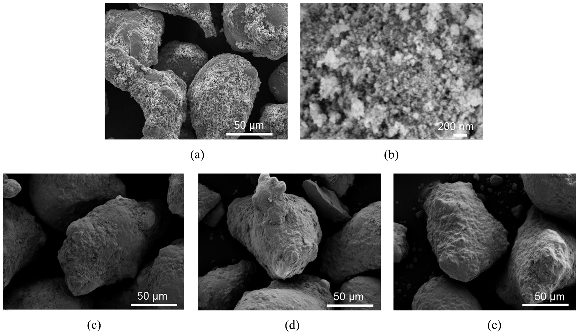
Morphologies of NiCoCrAlY powders with different nano-CeO2 mass fractions: (a) NiCoCrAlY powder, (b) Nano-CeO2 powder, (c) with nano-CeO2 mass fraction of 2%, (d) with nano-CeO2 mass fraction of 4%, and (e) with nano-CeO2 mass fraction of 6%.
Figure 2 shows the XRD analysis of NiCoCrAlY powders with the different nano-CeO2 mass fractions. The powders were mainly composed of Ni, Co, Cr, and Al phases, while Fe was in the impurity phase, Y was not detected because of its low content, indicating that the addition of nano-CeO2 powder had no effect on the phase compositions of NiCoCrAlY powders.
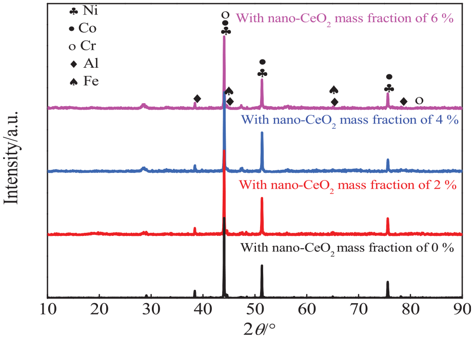
XRD analysis of NiCoCrAlY powders with different nano-CeO2 mass fractions.
Morphologies and XRD analysis of coating surfaces
Figure 3(a) shows the morphology of a NiCoCrAlY coating surface. The surface grains were mainly short dendrite NiTi2 as the reinforced phase, which was evenly distributed on the coating surface.
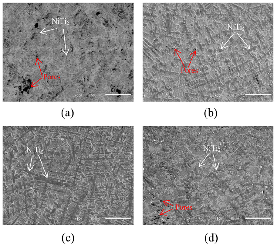
Morphologies of NiCoCrAlY coating surfaces with different nano-CeO2 mass fractions: (a) with a nano-CeO2 mass fraction of 0%, (b) with a nano-CeO2 mass fraction of 2%,(c) with a nano-CeO2 mass fraction of 4%, and (d) with anano-CeO2 mass fraction of 6%.
Figure 3(b) shows the morphology of NiCoCrAlY coating surface with the nano-CeO2 mass fraction of 2%. The contained CeO2 grains were obviously found on the coating. The porosity decreased markedly. The dendrites increased on the coating surface, and a small amount of cellular crystals was dispersed around the dendrite, indicating that the nano-CeO2 promoted the grain nucleation.
Figure 3(c) shows the morphology of NiCoCrAlY coating surfaces with the nano-CeO2 mass fraction of 4%. The coating surface was covered with dendrites, and the cellular crystals almost disappeared, indicating that the addition of nano-CeO2 promoted the formation of nuclei 24 and increased the nucleation rate. However, a small amount of CeO2 did not inhibit the growth of grains, and the large nuclei were connected to each other and grew up, resulting in the coarsening of grains.
Figure 3(d) shows the morphology of NiCoCrAlY coating surfaces with the nano-CeO2 mass fraction of 6%. The coarse dendrites were broken, and the cellular crystals were increased. The short dendrites and cellular crystals were dominant on the coating surface, indicating that a small amount of nano-CeO2 promoted the formation and growth of grains. 25 The nano-CeO2 destroyed the stable state of grain growth with the increase of nano-CeO2 mass fraction, and the grains grew into the small dendrites and cellular crystals, which played a role in fine grain strengthening. 26 After crystallization, nano-CeO2 became enriched at the grain boundary and reduced the surface tension and interfacial energy, which decreased the critical nucleation. The number of nucleation particles was increased to avoid grain coarsening, 27 and the NiTi2 phase experienced the process of grain increase, grain growth, and grain refinement.
Figure 4 shows XRD analysis of NiCoCrAlY coatings with the different nano-CeO2 mass fractions. The coatings were mainly composed of NiTi2, Ti3O, CoO, and β-Ti phases, and the addition of nano-CeO2 had little effect on the phase compositions,22,26 with no new phases. Ti on the coating was positively correlated with nano-CeO2, which increased the intensity of the Ti3O peak. 22 The molten pool contained nano-CeO2 and had better fluidity, which caused more Ti atoms in the substrate float up to form the reinforced phase. Ti and Co on the coating absorbed O in the air, which was preferentially adsorbed by α-Ti to form Ti3O. 28 This was because the oxygen solubilities in the α-Ti and β-Ti phases were 33.9% and 3.8%, respectively.
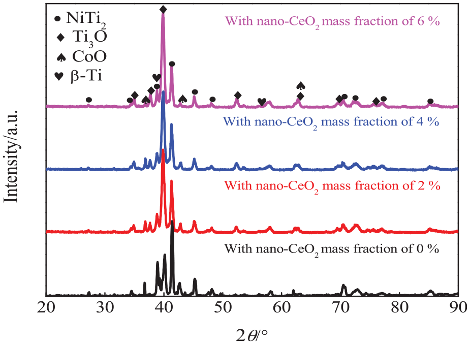
XRD analysis of NiCoCrAlY coatings with different nano-CeO2 mass fractions.
Morphologies of coating cross-sections
Figure 5(a) shows the morphology of a NiCoCrAlY coating cross-section. The bonding interface of coating substrates was in a zigzag shape with irregular protrusions. The deep cladding layer was formed on the region with fast thermal conductivity.
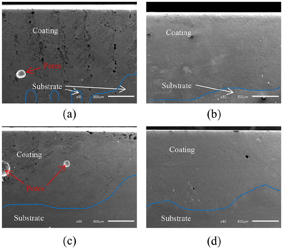
Morphologies of NiCoCrAlY coating cross-sections with different nano-CeO2 mass fractions: (a) with a nano-CeO2 mass fraction of 0%, (b) with a nano-CeO2 mass fraction of 2%, (c) with a nano-CeO2 mass fraction of 4%, and (d) with a nano-CeO2 mass fraction of 6%.
Figure 5(b)–(d) shows the morphologies of NiCoCrAlY coating cross-sections with the nano-CeO2 mass fractions of 2%, 4%, and 6%, respectively. The large serrated teeth at the interface between the coating and the substrate disappeared, suggesting that the nano-CeO2 improved the fluidity and heat transfer of the molten pool. The NiCoCrAlY coating with the nano-CeO2 mass fraction of 6% exhibited the micro-serration bonding at the interface, and the micro-serration enhanced its bonding strength and reduced crack sensitivity and shedding risk on the bonding sites.
Figure 6 shows the hardness distributions of NiCoCrAlY coating cross-sections with the different nano-CeO2 mass fractions. The average hardness values of NiCoCrAlY coatings with the nano-CeO2 mass fractions of 0%, 2%, 4%, and 6% were 867, 942, 957, and 1003 HV, respectively, which increased with the increase in the nano-CeO2 mass fraction; this was because the NiTi2-reinforced phase enriched on the skeleton structure improved their hardness. 29
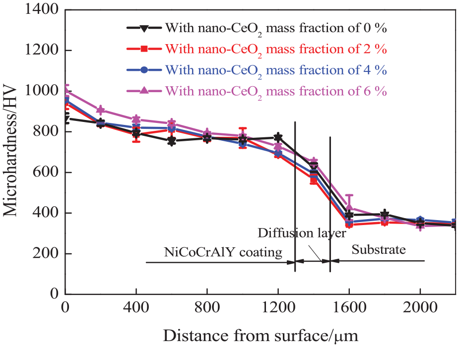
Hardness distribution of NiCoCrAlY coating cross-sections with different nano-CeO2 mass fractions.
COFs and wear rates
Figure 7(a) shows the COFs of nano-CeO2–reinforced NiCoCrAlY coatings versus wear time. The large fluctuations of COFs in the running-in period (0–2 min) were due to the removal and redistribution of particles on the contact surfaces. The COFs remained at 0.69 in the range of 2–20 min, while those in the range of 20–30 min presented an upward trend and reached 0.771 at 30 min. The COF fluctuation was related to the oxides. The COFs of nano-CeO2–reinforced NiCoCrAlY coatings were lower than 0.7; this was because the nano-CeO2 increased the adhesion of oxides on the coating. The COFs of nano-CeO2–reinforced NiCoCrAlY coatings presented a rapid decrease, rise, and stable states; this was because the adhered oxides on the coating were broken, which caused the COFs to fluctuate. 30 The average COFs of NiCoCrAlY coatings with the nano-CeO2 mass fractions of 2%, 4%, and 6% were 0.655, 0.636, and 0.615, respectively, suggesting that the nano-CeO2–reinforced coatings had lower COFs. 31 The standard deviation of NiCoCrAlY coatings with the nano-CeO2 mass fractions of 2%, 4%, and 6% in the time range of 5–30 min were 0.030, 0.019, and 0.027, respectively, while that of NiCoCrAlY coating was 0.035, showing that the nano-CeO2–reinforced coatings also had more stable friction processes.
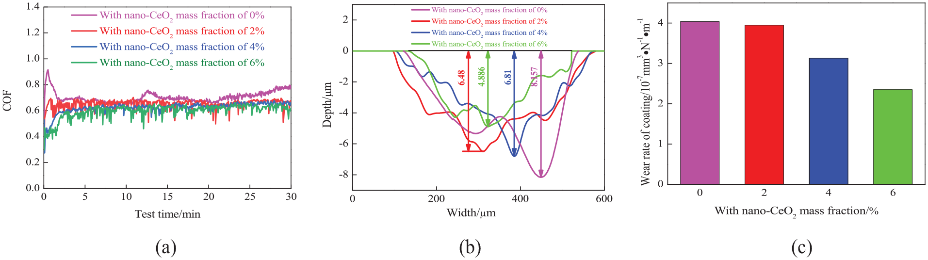
Coefficients of friction versus wear time, and profiles of worn tracks and wear rates on NiCoCrAlY with differentnano-CeO2 mass fractions: (a) coefficients of friction versus wear time, (b) profiles of worn tracks, and (c) wear rates.
Figure 7(b) shows the profiles of worn tracks on the nano-CeO2–reinforced NiCoCrAlY coatings. The depths of worn tracks with the nano-CeO2 mass fractions of 0%, 2%, 4%, and 6% were 8.157, 6.48, 6.81, and 4.886 µm, respectively, and the corresponding average wear depths were 4.359, 3.685, 2.976, and 2.717 µm, respectively, which decreased with the increase of nano-CeO2 mass frictions.
Figure 7(c) shows the wear rates of nano-CeO2–reinforced NiCoCrAlY coatings. The wear rates of NiCoCrAlY coating with the nano-CeO2 mass fractions of 0%, 2%, 4%, and 6% were 4.04 × 10⁻⁷, 3.95 ×10⁻⁷, 3.13 ×10⁻⁷, and 2.35 × 10⁻⁷ mm3 N−1 m−1, respectively, which decreased with the increase of nano-CeO2 mass fraction. The fined grains were distributed on the coating with the nano-CeO2 mass fraction of 6%, which effectively deduced the wear rate, and the effect of nano-CeO2 on the wear resistance was consistent with the hardness.19,32
Morphologies and XRD analysis of worn tracks
Figure 8(a) shows the morphology of worn tracks on the NiCoCrAlY coating. The plastic deformation was obviously found on the worn track, which was a typical adhesive wear feature. The felled oxides scratched the coating, leading to abrasive wear.
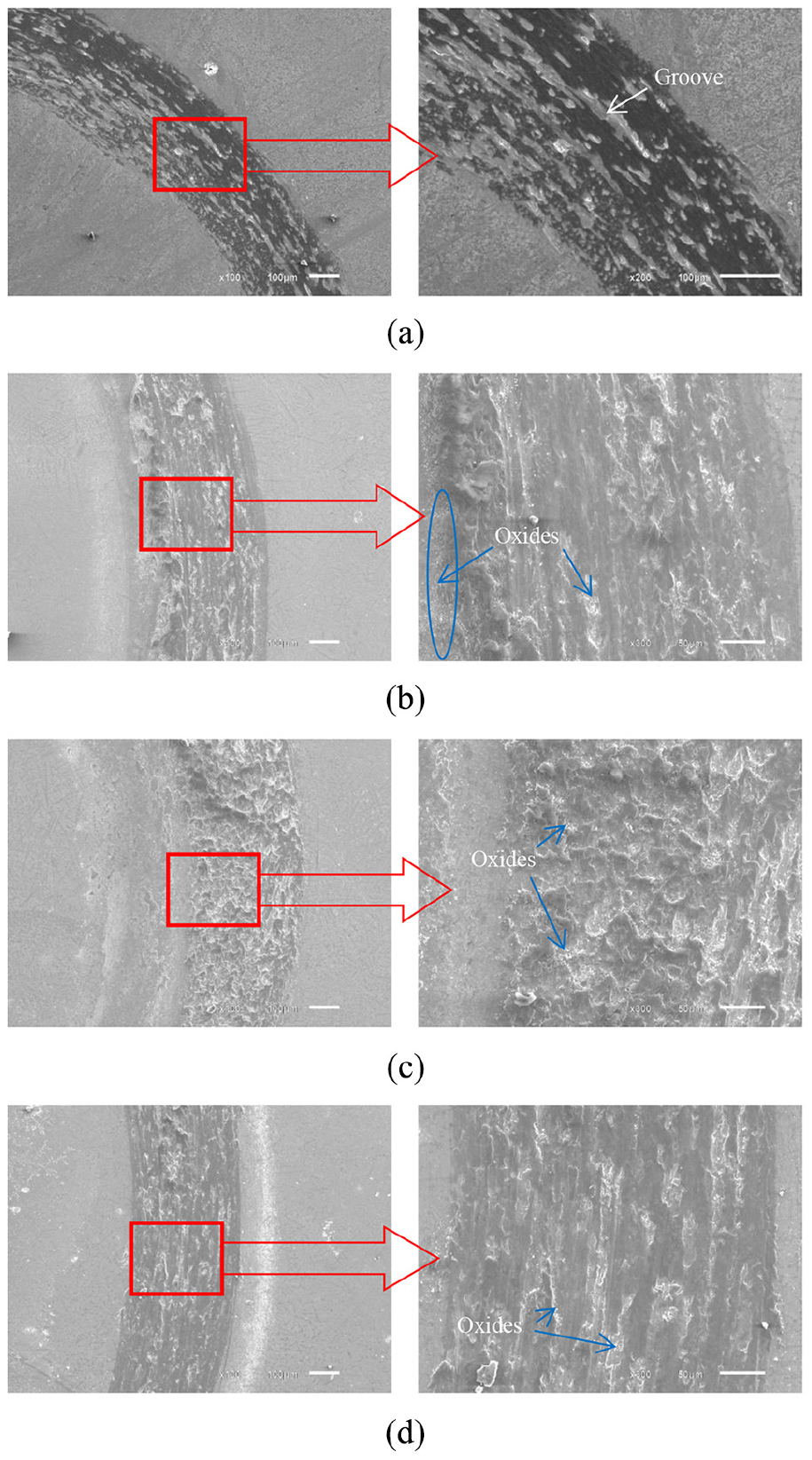
Morphologies of worn tracks with different nano-CeO2 mass fractions: (a) with a nano-CeO2 mass fraction of 0%, (b) with a nano-CeO2 mass fraction of 2%, (c) with a nano-CeO2 mass fraction of 4%, and (d) with a nano-CeO2 mass fraction of 6%.
Figure 8(b) shows the morphology of worn tracks on the NiCoCrAlY coating with the nano-CeO2 mass fraction of 2%. There was also obvious plastic deformation on the worn track, and the wear debris was produced on the wear couples, which caused micro-cutting and grooving.33,34 A large number of fallen oxides were observed on the grooves of worn tracks, indicating that the wear mechanism was adhesive wear and oxidation wear, accompanied by slight abrasive wear.
Figure 8(c) shows the morphology of worn tracks on the NiCoCrAlY coating with the nano-CeO2 mass fraction of 4%. The plastic deformation was more obviously observed on the worn tracks; this was because the coarse grains reduced the plasticity, and the felled oxides reduced the degree of oxidation wear.
Figure 8(d) shows the morphology of worn tracks on the NiCoCrAlY coating with the nano-CeO2 mass fraction of 6%. More nano-CeO2 refined the coating structure and improved the plastic deformation of worn tracks, and the high hardness increased deformation resistance with the addition of nano-CeO2. 35 The shedding oxides on the worn track reduced the oxidation wear. 19 It was concluded that the degrees of plastic deformation and oxide on the worn track with the nano-CeO2 mass fraction of 6% were the lowest among the four kinds of coatings.
Figure 9(a) shows the wear mechanism of NiCoCrAlY coating. The oxide layer was formed on the worn track at a high temperature because of the oxidation of alloy elements,36,37 and the tribo pair rubbed violently with the coating and produced a large amount of debris on the marked green zone. At the same time, at high temperatures, the welding junctions occurred on purple zone between the tribo pair and the coating, which lead to adhesive wear.
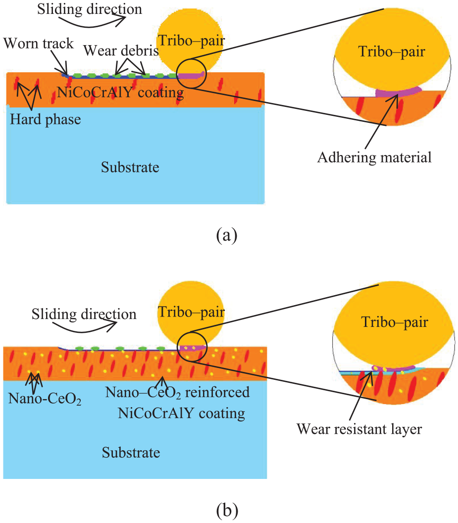
Schematic diagram of the wear mechanism on NiCoCrAlY coatings with different nano-CeO2 mass fractions: 36 (a) NiCoCrAlY coating and (b) nano-CeO2–reinforced NiCoCrAlY coating.
Figure 9(b) shows the wear mechanism of nano-CeO2–reinforced NiCoCrAlY coating. Under the action of cyclic shearing stress, the hard phases were worn out slowly, 36 and the number of hard phases were obviously refined and increased.22,26 The wear degree of hard phases was slowed down, and the hard wear-resistant layer was formed on the light blue zone, which was aggregated by the hard phases.
Figure 10 shows XRD analysis of worn tracks with the different nano-CeO2 mass fractions. The new phases of AlTi3 and (Ni, Co)2Ti4O were formed on the worn tracks; among them, Ni2Ti4O was a solid solution formed by the dissolution of O in NiTi2, which was oxidized to reduce the Ti oxide; 38 Co2Ti4O was a solid solution formed by the Co atoms replacing the Ni atoms in Ni2Ti4O; and the AlTi3 phase was a new enhanced phase formed at high temperatures. The Ti3O phase vanished on the surface of worn tracks. The peaks of Ti2O3 were observed at 40.22°, 42.627°, and 48.756°, indicating that Ti3O was oxidized to Ti2O3, which was related to the low contents of NiTi2 and Ni2Ti4O.
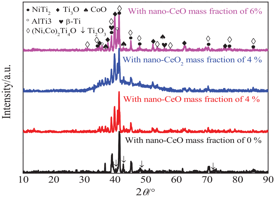
XRD analysis of worn tracks on NiCoCrAlY coatings with different nano-CeO2 mass fractions.
Line scan analysis of worn tracks
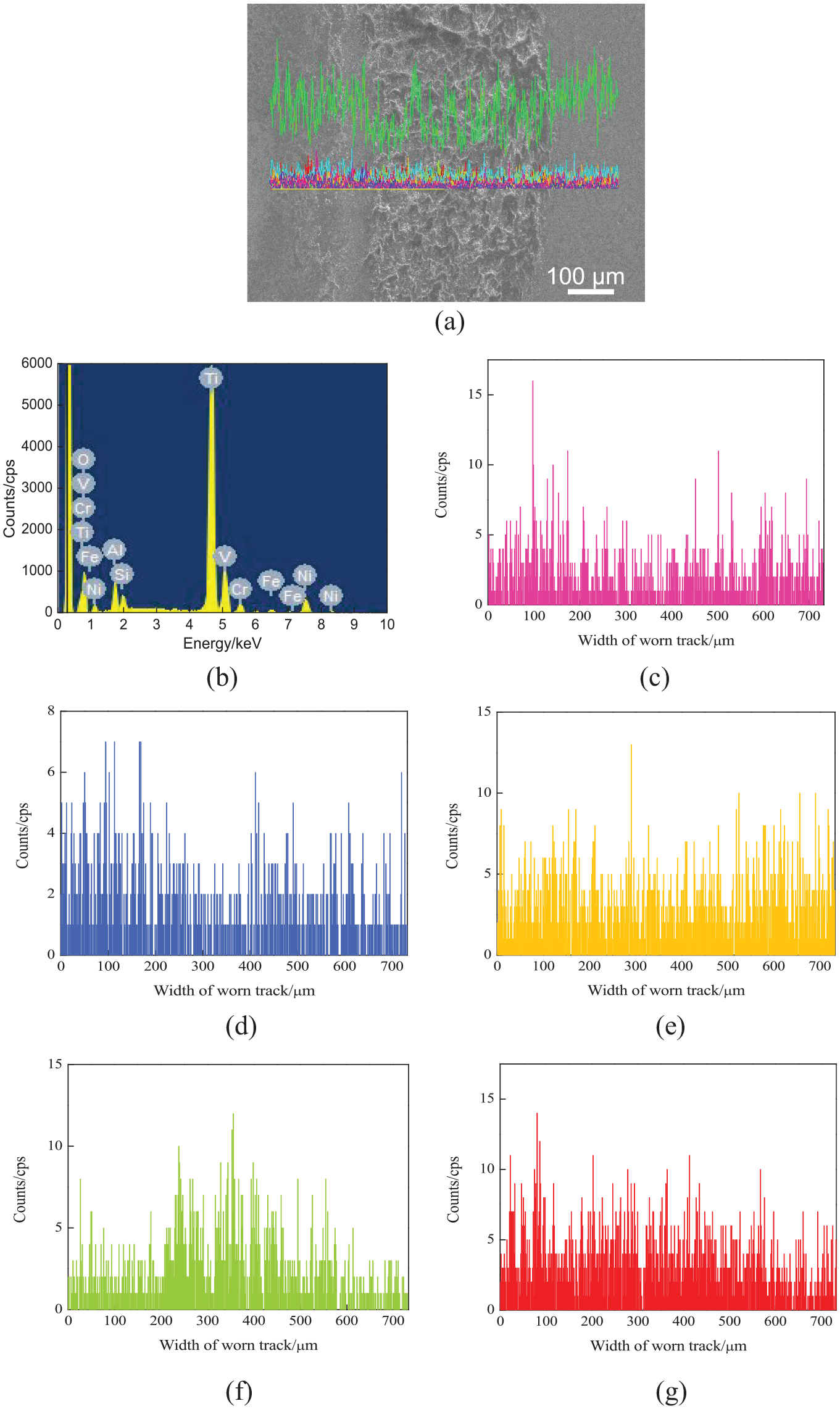
Figure 11(a) shows the line-scanned position of worn tracks on the NiCoCrAlY coating. The mass fractions of chemical elements (mass, %) were as follows: C 1.7, O 26.05, Al 3.02, Si 0.66, Ti 42.4, V 1.84, Cr 4.47, Co 0.74, Ni 18.57, and Y 0.57, as shown in Figure 11(b). The Ni, Co, Cr, Al, and Y contents on the worn track decreased slightly, as shown in Figure 11(c)–(f). The Si content increased obviously on the worn track, which came from the tribo pair, and the wear mechanism was adhesive wear, as shown in Figure 11(g). The O content increased on worn tracks; there was oxidation wear, as shown in Figure 11(h).
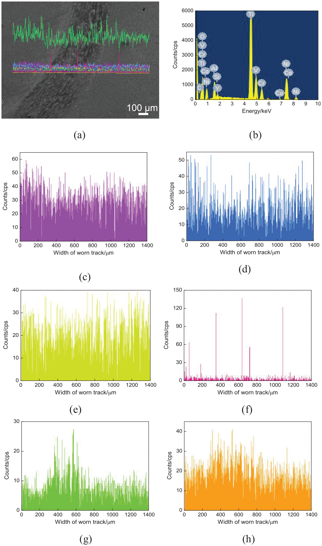
Line scan analysis of worn tracks on NiCoCrAlY coating: (a) line scan position, (b) result of line scan analysis, (c) Ni content, (d) Cr content, (e) Al content, (f) Y content, (g) Si content, and (h) O content.
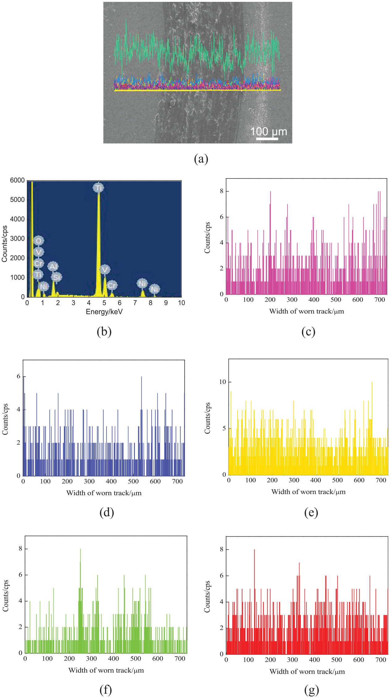
Figure 12(a) shows the line-scanned position of worn tracks on the NiCoCrAlY coating with the nano-CeO2 mass fraction of 2%. The mass fractions of chemical elements (mass, %) were as follows: O 30.18, Al 3.59, Si 0.81, Ti 51.46, V 2.47, Cr 2.61, and Ni 8.89, as shown in Figure 12(b). The Ni, Cr, and Al contents on the worn track decreased slightly, as shown in Figure 12(c)–(e). The contents of Cr and Ni decreased, while those of Ti and V increased, indicating that nano-CeO2 caused more Ti to enter the molten pool. 28 The additional reinforced phases were formed, and the coating elements were further diluted. The contents of Si and O increased on the worn track, and the wear mechanism was adhesion wear and oxidation wear, as shown in Figure 12(f) and (g).
Line scan analysis of worn tracks on NiCoCrAlY coating with a nano-CeO2 mass fraction of 2%: (a) line-scanned position, (b) result of line scan analysis, (c) Ni content, (d) Cr content, (e) Al content, (f) Si content, and (g) O content.
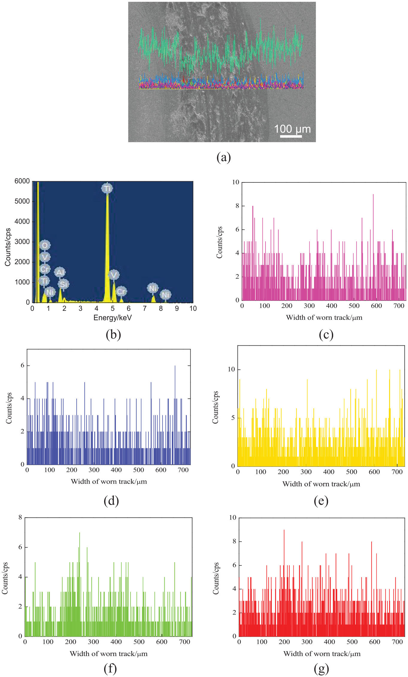
Figure 13(a) shows the line-scanned position of worn tracks on the NiCoCrAlY coating with the nano-CeO2 mass fraction of 4%. The mass fractions of chemical elements (mass, %) were as follows: O 34.3, Al 3.12, Si 1.49, Ti 48.58, V 1.92, Cr 2.06, Ni 7.48, and Fe 1.04, as shown in Figure 13(b). The Ni, Cr, Al, and Y contents on the worn track decreased slightly, as shown in Figure 13(c)–(e). The Si content was higher than that with the nano-CeO2 mass fraction of 2%, showing that more Si was stuck on the worn track. The wear mechanism was adhesive wear, as shown in Figure 13(f). The content of O increased at the worn track. This meant that there was oxidative wear on the worn track, as shown in Figure 13(g).
Line scan analysis of worn tracks on NiCoCrAlY coating with nano-CeO2 mass fraction of 4%: (a) line-scanned position, (b) Result of line scan analysis, (c) Ni content, (d) Cr content, (e) Al content, (f) Si content, and (g) O content.
Figure 14(a) shows the line-scanned position of worn tracks on the NiCoCrAlY coating with the nano-CeO2 mass fraction of 6%. The mass fractions of chemical elements (mass, %) were as follows: O 31.67, Al 4.1, Si 0.91, Ti 49.89, V 2.34, Cr 2.22, and Ni 8.87 as shown in Figure 14(b). Co was detected on the worn track, which was related to the reduction of CoO peak. The Ni, Cr, and Al contents on the worn track decreased slightly, as shown in Figure 14(c)–(e). The Si content increased on the worn track, indicating that there was adhesive wear, as shown in Figure 14(f). The O content did not change, indicating that the degree of oxidation wear was reduced, as shown in Figure 14(g). Ce was not detected, which further proved that the addition of nano-CeO2 had no obvious effect on the phase composition and phase composition.26,28
Line scan analysis of worn tracks on NiCoCrAlY coating with a nano-CeO2 mass fraction of 6%: (a) line-scanned position, (b) result of line scan analysis, (c) Ni content, (d) Cr content, (e) Al content, (f) Si content, and (g) O content.
Conclusion
Based on the experimental results presented above, the conclusions can be drawn as follows:
The nano-CeO2–reinforced NiCoCrAlY coatings are mainly composed of NiTi2, Ti3O, CoO, and β-Ti phases. Nano-CeO2 promotes grain refinement, while the Ni2Ti4O and AlTi3 phases are formed after the wear test, which enhance coating hardness.
The average COFs of NiCoCrAlY coatings with the nano-CeO2 mass fractions of 0%, 2%, 4%, and 6% are 0.699, 0.655, 0.636, and 0.615, respectively, and the corresponding wear rates are 4.04 × 10⁻⁷, 3.95 × 10⁻⁷, 3.13×10⁻⁷, and 2.35×10⁻⁷ mm3 N−1 m−1, respectively, which decrease with the increase of nano-CeO2 mass fraction.
The wear mechanism of nano-CeO2–reinforced NiCoCrAlY coating is adhesive wear and oxidation wear, accompanied by slight abrasive wear, while the degree of oxidation wear decreases with the increase of nano-CeO2 mass fraction.
Footnotes
Declaration of conflicting interests
The author(s) declared no potential conflicts of interest with respect to the research, authorship, and/or publication of this article.
Funding
The author(s) disclosed receipt of the following financial support for the research, authorship, and/or publication of this article: This work was supported by the Key Research and Development Project of Jiangsu Province (BE2016052).