
Abstract
Cobalt chromium molybdenum alloy and highly cross-linked polyethylene are selected as the counterpairs in this study to carry out friction and wear testing over different ellipse motion paths to explore the influence of ellipse motion path on friction and wear of prosthesis materials. Here, the analytical methods for the periodic friction coefficient and special point wear are proposed to investigate the relationship between motion paths and tribological properties. The damage mechanism model of high cross-linked polyethyleneunder ellipse motion paths was established, which revealed the connection among material composition, motion paths and friction and wear mechanism. The results show that the friction coefficient and wear morphology are directly affected by changes in motion paths. The friction coefficient decreases with increasing aspect ratios, and the wear profile depth increases with increasing aspect ratios. The spatially resolved friction coefficient curve distinctly exhibits periodic “W”-type variation in elliptical motion paths. The friction coefficient shows maximum values at the long-axis endpoints and minimum values at the short-axis endpoints. There are different wear morphologies in different characteristic areas over the elliptical wear paths. The wear profile depth and width at the long-axis endpoints are larger than those at the short-axis endpoints, and the wear morphology is also more serious.
Introduction
The tribological behavior of a prosthetic material is closely related to the movement form of the counter pairs due to the diversity of lower limb joint movements (when walking, running, jumping, etc.) and the complexity of movement forms between the hip femoral head and the acetabular cup. By tracing the marker points on the femoral head prosthesis 1 and computer simulation, 2 it is found that the sliding track shapes on the femoral head are mainly ellipse and “8”-shaped, and the sliding tracks on the acetabular cup are mainly 8-shaped, straight line, asymmetric ellipse and ellipse 3 by different hip simulators. The motion form of hip joint is complex and the sliding track is diverse rather than simple straight line motion, so the evaluation of hip prosthesis material should also be carried out under different motion paths.
The relative motion between femoral head and acetabular cup has an important influence on the wear modes of friction pairs, particularly in acetabular material, as the main wear object of friction pair.4,5 Some researchers hold that the wear performance of semi-crystalline polymer prosthesis materials should be measured under multidirectional stress field rather than unidirectional motion,6,7 because the kinematics of artificial joint shows that the motion and stress of hip joint and knee joint are multidirectional. Bennett et al.
8
systematically researched the movement loci and tribological behavior for different total hip replacement patients and normal subjects. It was found that the average sliding distance and aspect ratios range for patients was greater than those for normal subjects. Patients produce multidirectional motion loci and tend to experience more wear of UHMWPE than patients with more unidirectional motion loci. Saikko et al.
9
demonstrated that the wear factor showed a strong positive relationship with the aspect ratio. When the aspect ratio is less than 5.5 (the aspect ratio less than 5.5 corresponds to 0.1818 <
Wang reported that the UHMWPE with a unique molecular structure allows linear tracking of molecular orientation and can undergo strain hardening for improving wear resistance.15,16 Turell et al. 17 considered that shear stress and tensile stress are generated simultaneously in multidirections on the surface of polyethylene under multidirectional motion, which are strengthened in the principal direction and weakened in the perpendicular to the principal direction. This phenomenon, called orientation softening, makes material be removed by sub-directional intermolecular splitting. From the perspective of cross-shearing, Dunn et al. found that in the predominant sliding direction of friction, the fibrils are oriented and elongated to result in low friction and wear. However, in the perpendicular direction, the cross-linked structure is destroyed, which hinders the formation of a stable sliding interface, leading to wear. 14 Sub-micron wear particles were created during long-term friction and wear, which can lead to osteolysis and possible revision of the implant.18,19 The highly cross-linked polyethylene (XLPE), the second-generation polyethylene, is widely used in acetabular cup, knee liner, etc. due to the higher wear resistance20,21 since the feasibility of replacing traditional polyethylene implanted into the human body has been confirmed. 22 Turell et al. 17 studied the impact of cross-shear stress on UHMWPE and XLPE in different aspect ratios along rectangular sliding paths. It was shown that the shear stress response to stimuli of UHMWPE was significantly higher than that of XLPE.
At present, wear tests in multidirectional motion mostly use UHMWPE, which is greatly affected by sliding track shapes. However, studies on the multidirectional motion friction and wear behavior of XLPE are absent, and the relationship among material composition, motion paths and friction and wear mechanism is still unclear. In addition, current research on friction and wear in multidirectional motion paths is mainly focused on general analysis of the overall influence of different motion paths on the friction coefficient and wear morphology of prosthetic materials. There are no characteristic or periodic analyses of the specific path of the damage mechanism. Hence, the friction and wear experiments of CoCrMo/ XLPE under ellipse motion paths with different aspect ratios were carried out to simulate the ellipse wear path on acetabular surface of hip joint motion. By analyzing the periodic variation of friction coefficient and the special point wear (the wear of the special points of the motion path with the maximum or minimum curvature radius, such as the long-axis endpoints and the short-axis endpoints of an ellipse) to explain the tribological properties of XLPE, and then the damage model of XLPE was established to explore the relationship among material composition, motion paths and friction and wear mechanism. These work will provide experimental basis for evaluating the friction and wear of artificial joint prosthesis materials, especially acetabular materials, and provide a theoretical basis for the manufacture of artificial hip materials, which is of great significance to prolong the life span of prosthesis and improve the living conditions of patients undergoing joint replacement.
Experiment
Experimental installation
The ball-disc test is carried out with a custom-made multidirectional motion path friction and wear tester which can simulate the wear condition of the distinct points on prosthesis materials to itself and friction pairs in hip simulator (Figure 1). The installation consists of four parts: the normal force load module, the two-dimensional motion platform module, the temperature control module and the software control module. The normal force load module controlled by closed-loop force feedback, supports a constant force load, linear load and step load. The normal load ranges from 0 N to 200 N. The two-dimensional motion platform module, equipped with X-and-Y direction servo motors, can run various multidirectional motion paths stably under the cooperative control of G code files. The limit distance of the platform is 80 × 80 mm. The three-dimensional force sensor between the normal force load module and the two-dimensional motion platform module collects the normal force and friction in the X and Y directions. The force range of the sensor is 200/200/200 N, and the accuracy is 0.1%. The temperature control module mainly controls the bath temperature with lubricating fluid. The temperature of this module ranges from 20°C to 60°C. The function of the software control system module is to accept the forces supplied by the three-dimensional force sensor and the temperature provided by the temperature control module, as well as to monitor other modules with feedback.
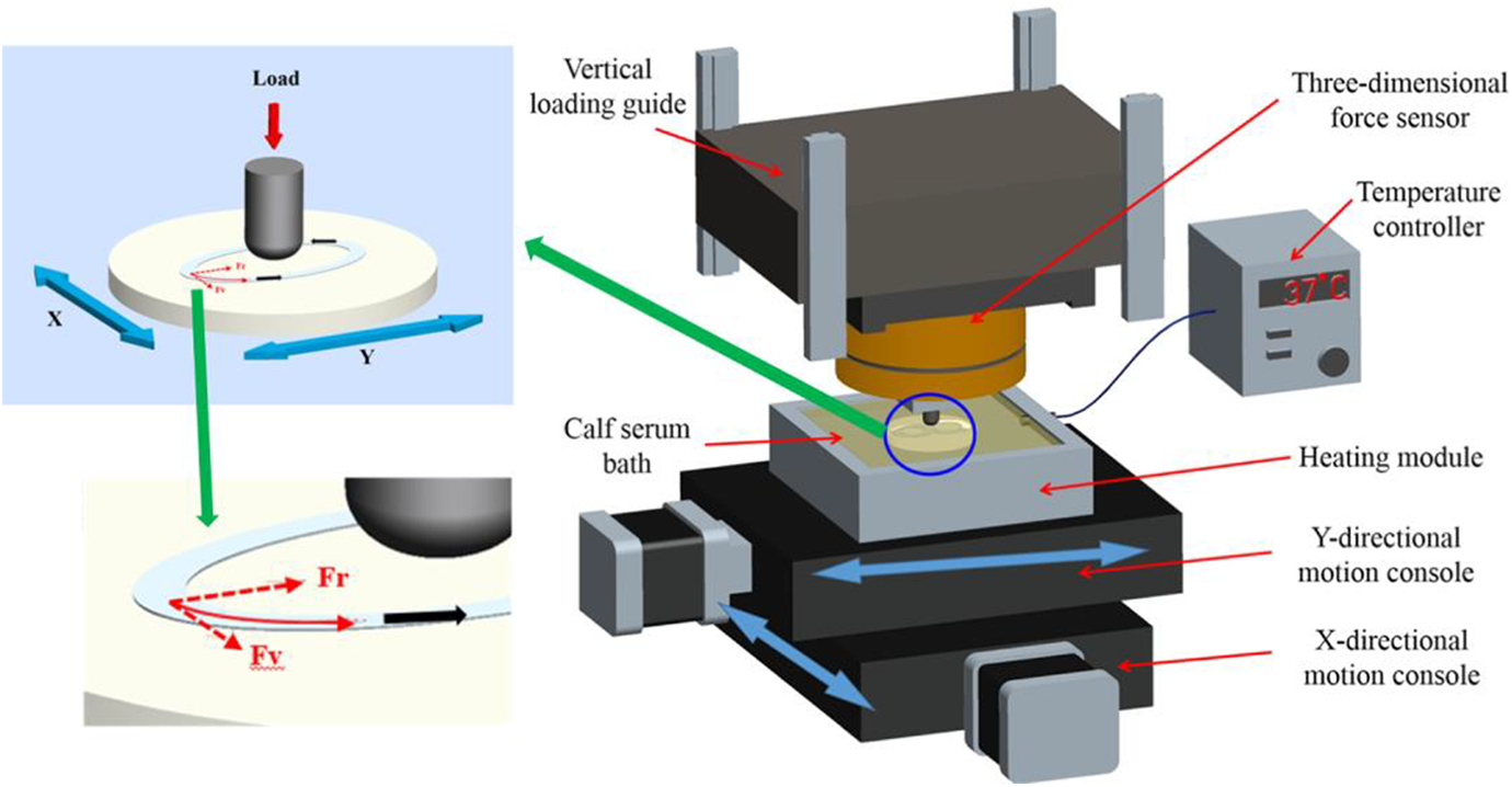
The multidirectional motion path friction testing device.
Materials
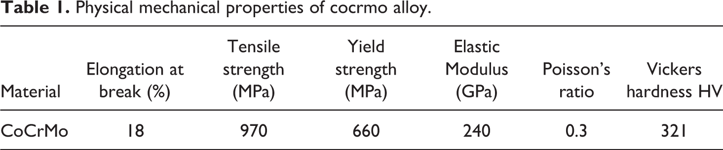
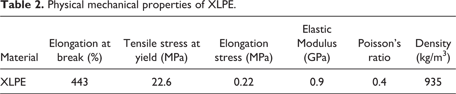
In this experiment, the contact geometry of the hip joint prosthesis is simplified, as shown in Figure 1. The replacement material for the distinct points on femur is a hemispherical cylindrical CoCrMo alloy with a roughness of Ra ≤ 0.1 µm (Articular surface requirements for metal femoral components of the artificial hip prosthesis), provided by Jiangsu Okoni Medical Technology Development Co.Ltd. The physical and mechanical properties of CoCrMo alloy are shown in Table 1. The acetabular materials using XLPE disc samples were purchased from Kuajun Plastic Trade (Shanghai) Co., Ltd. The XLPE disc sample was ground using alumina sandpaper and then polished on a polishing machine with a roughness of Ra ≤ 2 µm (artificial hip joint prosthesis facet requirements) before wear testing. The physical and mechanical properties of XLPE are shown in Table 2. The geometries of the samples of CoCrMo alloy pin and XLPE disc are shown in Figure 2. Calf serum (FBS, Protein content 38 g/L, volume fraction 25%) was selected as the lubricant and produced by Hangzhou Sijiqing Bioengineering Materials Co. Ltd.
Physical mechanical properties of cocrmo alloy.
Physical mechanical properties of XLPE.
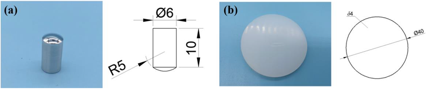
The geometries of the samples: (a) CoCrMo alloy pin, (b) XLPE disc.
Methods
This paper is concentrated on the elliptical motion path with the elliptical shape extending from a circular to a straight line with a certain perimeter (25 mm) to simplify the wear paths on femoral head at different positions in document 4. The aspect ratio value (
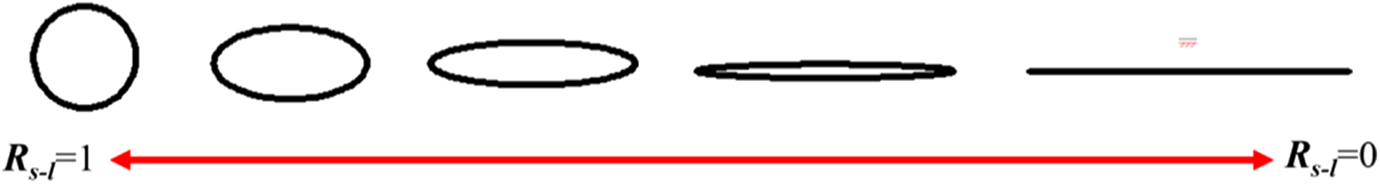
The motion path shape diagram.
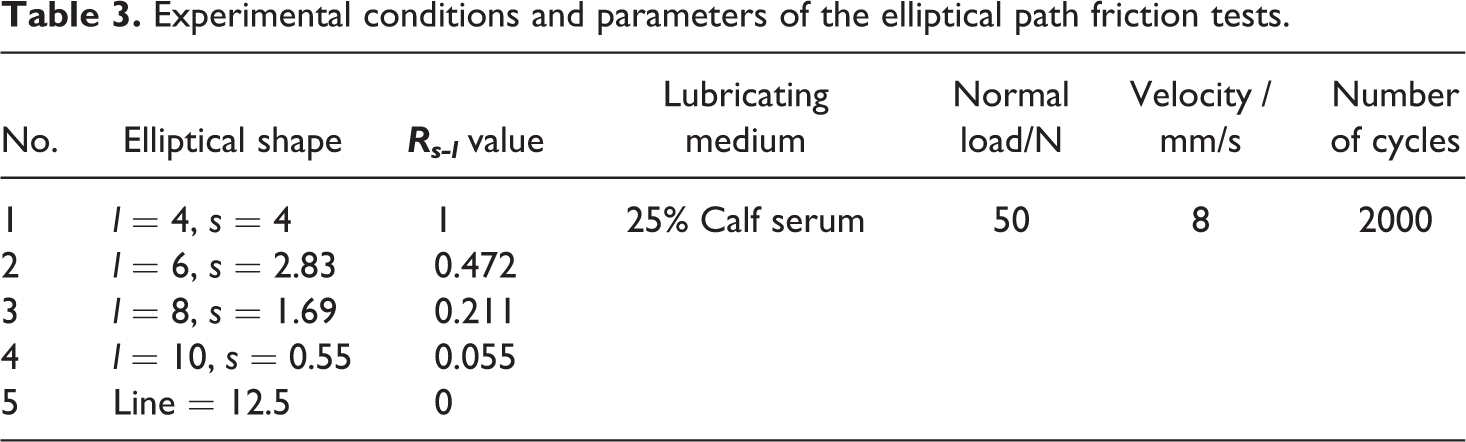
Experimental conditions and parameters of the elliptical path friction tests.
After the tests, the data of the motion path displacement and the data of the normal force, friction coefficient, etc. are analyzed by Origin software to explore the friction behavior under different motion paths. In addition, according to the principle of time correspondence between the two data systems, data points are extracted to analyze their periodicity. the wear morphologies are observed with a Keynes high-speed camera and a scanning electron microscope, and the three-dimensional morphology, wear profile, wear scar depth, etc. are obtained using laser confocal microscopy to research the damage mechanism of XLPE.
Results
Tribological properties in different elliptical shape
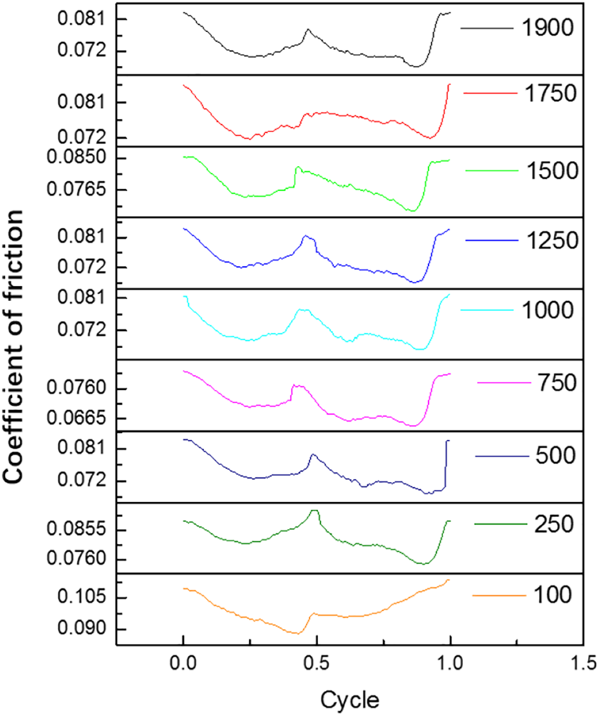
Figure 4 shows the cycle-dependent friction coefficients curves consisted of average friction coefficients for each cycle of the contact pairs of CoCrMo and XLPE with different
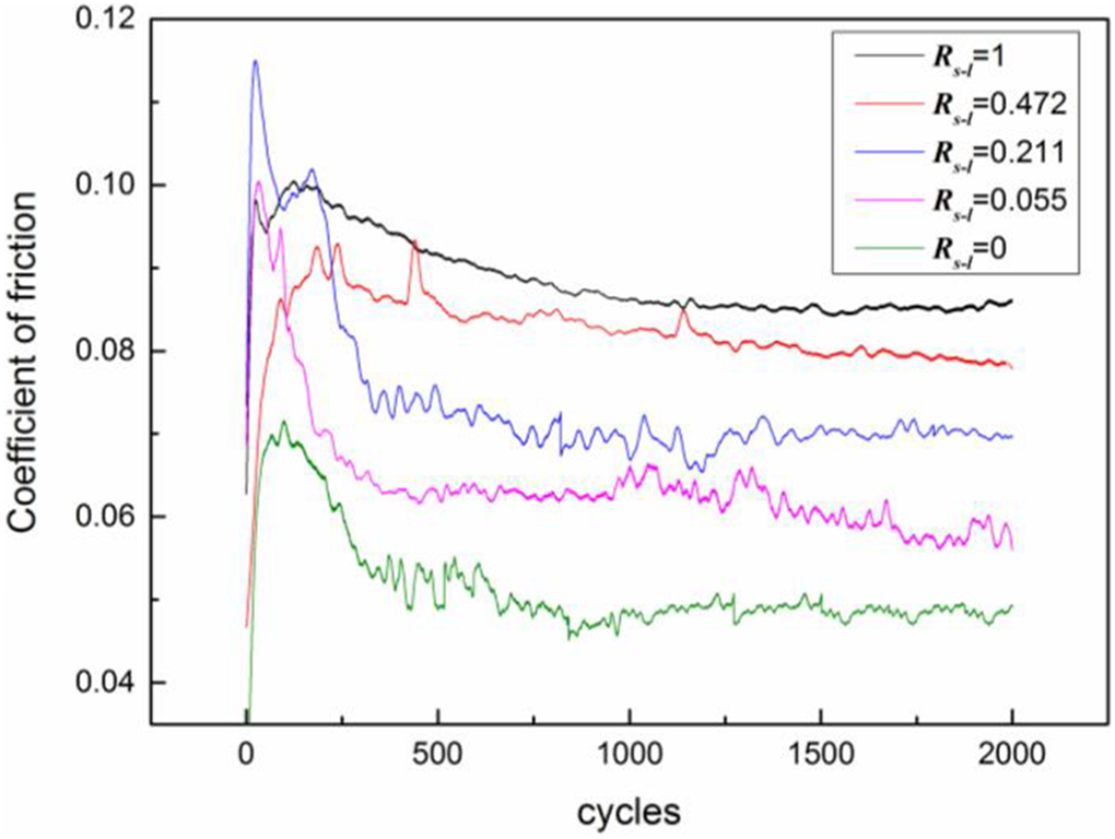
Cycle-dependent curve of the friction coefficient.
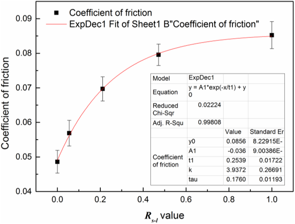
The relationship between the
Figure 6 shows the wear morphologies of CoCrMo under different
Wear morphologies of CoCrMo under different
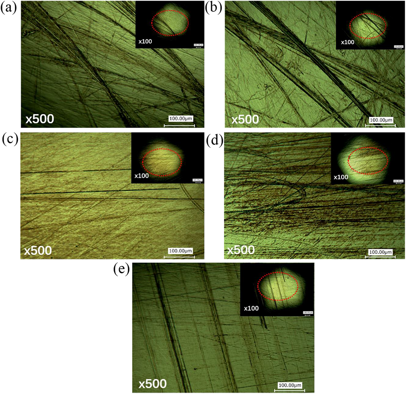
Figure 7 shows the wear morphologies and SEM micrograph of the left long-axis end region of the elliptical wear path of XLPE under different
Wear morphologies and SEM micrograph of the left long-axis end region of the elliptical wear path of XLPE under different
Figure 8 shows the wear profile of the left long-axis end region of the elliptical wear path of XLPE under different
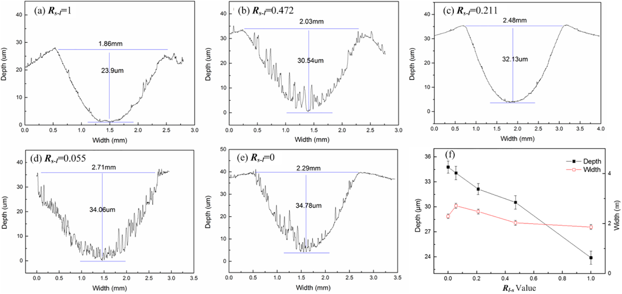
Wear profile of the left long-axis end region of the elliptical wear path of XLPE under different
Periodic analysis
Friction coefficient
In this chapter, periodic analysis of the data of the
The curve of the friction coefficient.
The friction coefficient curves of different cycles.
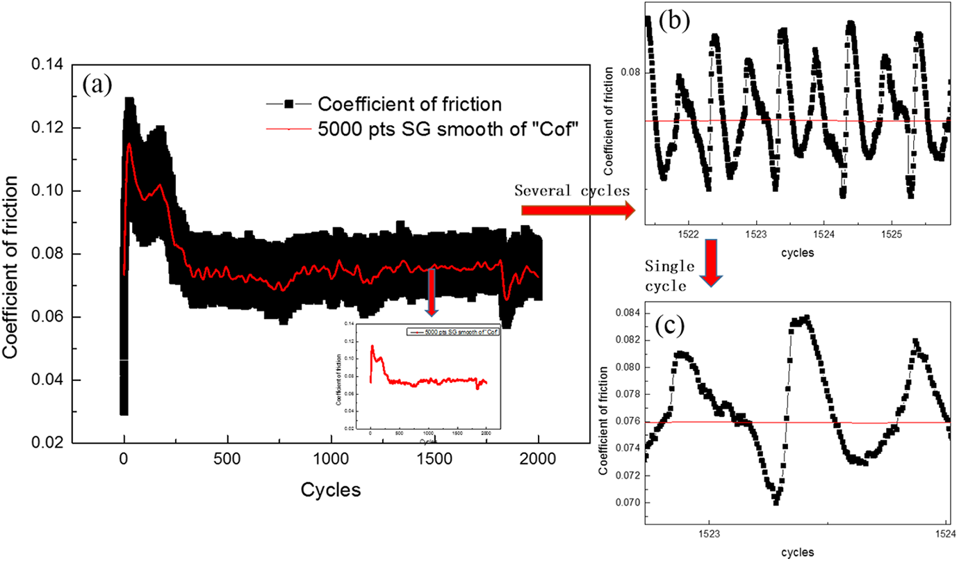
The data of the path and friction coefficient for any period of the stable cycle are selected as shown in Figure 11 to investigate the relationship between the path position and the friction coefficient on the basis of the time correspondence of the data. Surprisingly, the friction coefficients of the special points of the elliptical motion path where with the maximum or minimum curvature radius, such as the long-axis endpoints (A, C) and the short-axis endpoints (B, D), have obvious characteristics. The long-axis endpoints (A, C) of the elliptical motion path have maximum friction coefficients (1, 3, 5), corresponding to the peak positions of the “W” pattern, and the short-axis endpoints (B, D) of the elliptical motion path have minimum friction coefficients (2, 4), corresponding to the valley positions of the “W” pattern. The curvature radius at the long-axis end regions of the elliptical wear path is larger, the relative sliding velocity and the relative velocity change rate is higher, the material deformation is serious without effective recovery to make material accumulate to form folds, and the friction coefficient is larger. On the contrary, the curvature radius at the short-axis end regions is smaller, the relative sliding velocity and the relative velocity change rate is little and gentle, the friction coefficient is smaller. Then, the friction coefficients at the ends of the long- and short-axis of the 100th, 250th, 500th, 750th, 1000th, 1250th, 1500th, 1750th, and 1900th cycles are analysed as shown in Figure 12, and the results were in accord with the above laws.
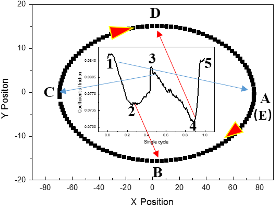
The relationship between the path position and the friction coefficient.
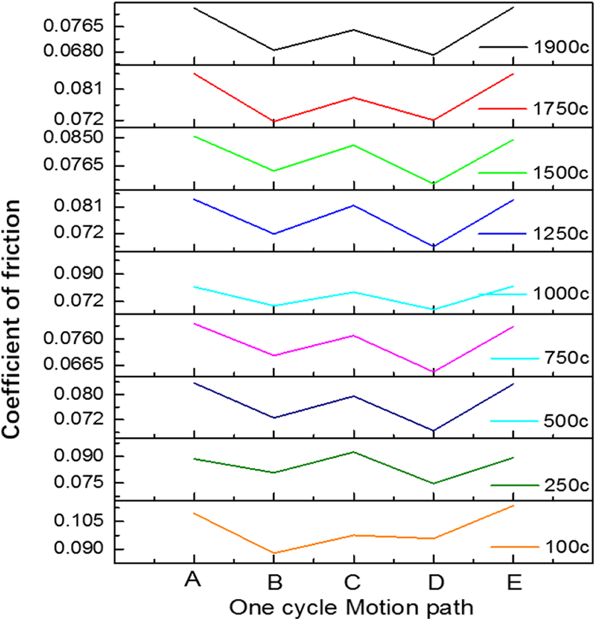
The relationship between the path position and friction coefficient in different cycles.
Figure 13 shows the cycle-dependent curve of the friction coefficient at the elliptical path characteristic points (A (E), B, C, D). At the different characteristic point, each curve performs the same trend of decreasing rapidly first, then rising gently, and finally decreasing slowly to a steady state. However, the friction coefficients at points A (E) and C are always higher than those at points B and D, which is related to the curvature radius of the wear path.
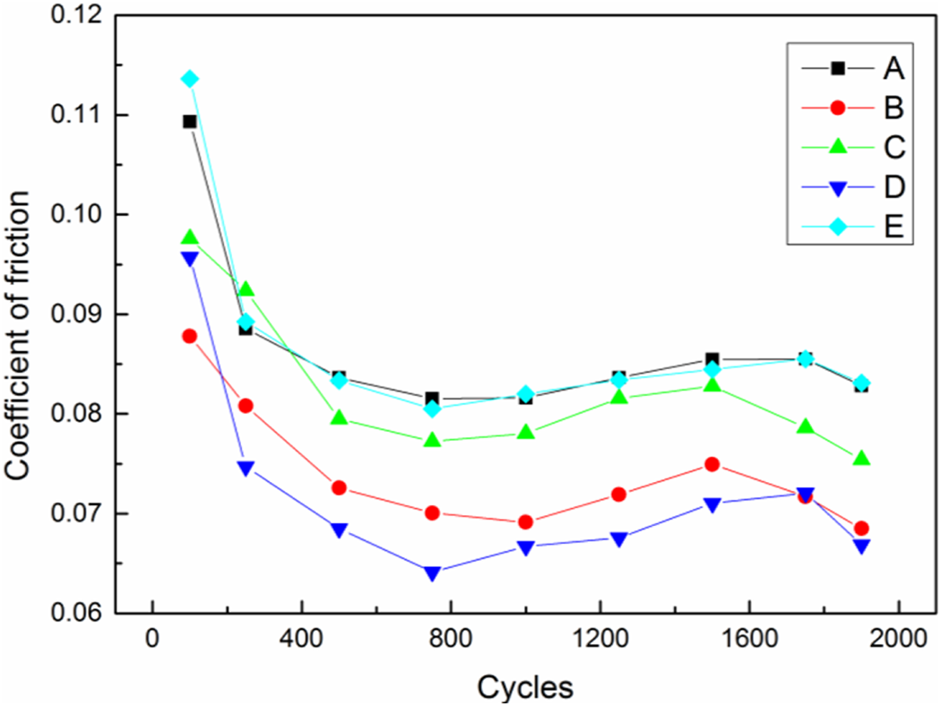
Cycle-dependent curve of the friction coefficient at the elliptical path characteristic points.
Wear morphology
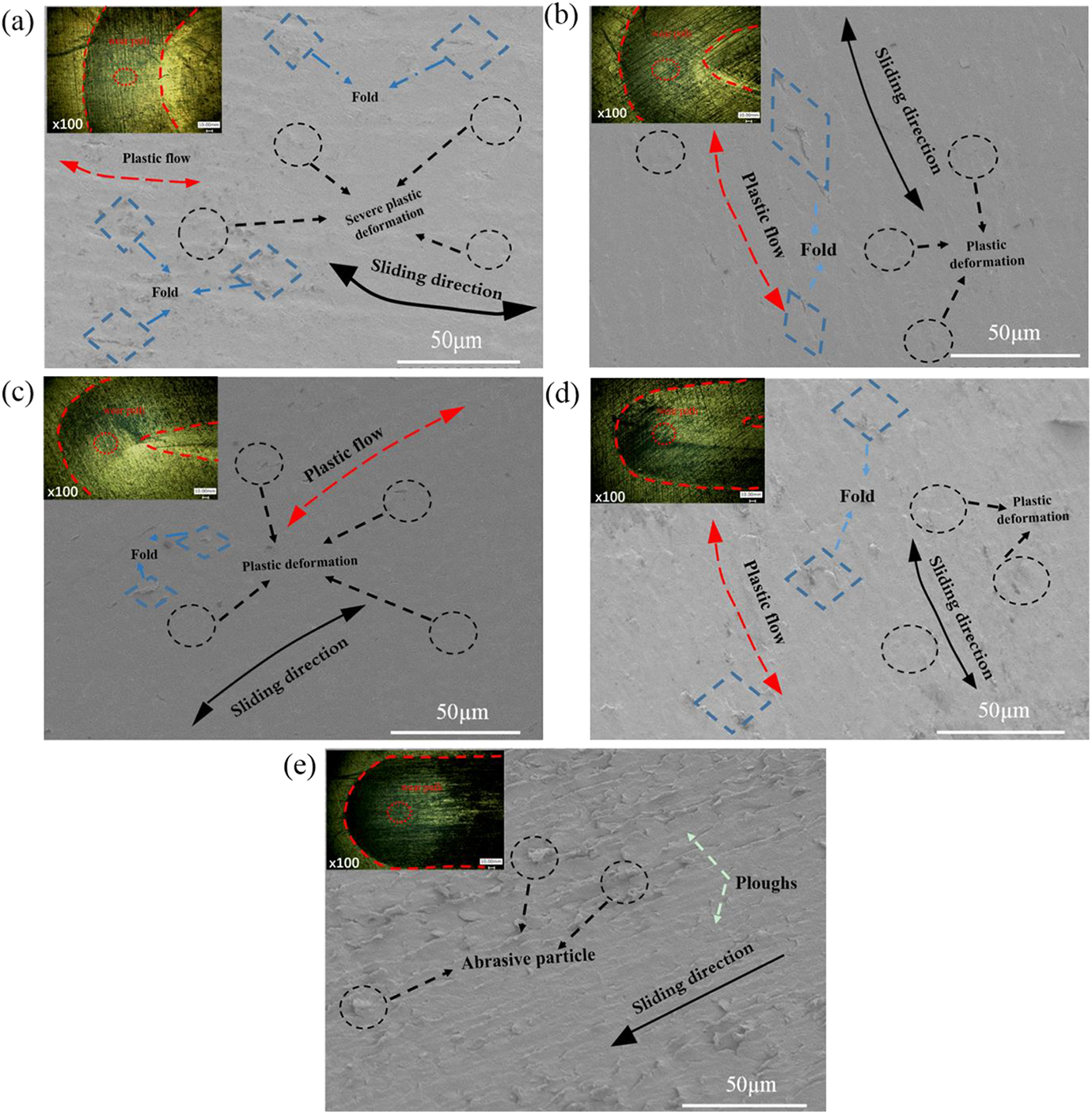
The wear morphologies of the XLPE surface at special point regions after 2000 cycles are shown in Figure 14. It was found from the three-dimensional morphologies that the worn pattern of XLPE is a “U” pattern and there are different degrees of micro- convexities in the edge region of the U-patterned wear, which is different from the smooth surface in the centre region. Evidently, the plastic deformation and the number and density of micro-convexities in the end region of the long-axis (Figure 14(a1), (c1)) are obviously higher than those in the end region of the short-axis (Figure 14(b1), (d1)). Furthermore, the wear profiles reflect the differences in the wear depth and wear width in different characteristic point regions, which indicates different characteristic regions of the same motion path have different degrees of normal plastic deformation under the same parameters. It can be seen that the wear depths of the two long-axis end regions of the elliptical wear path are 28.12 ± 2.5 µm (Figure 14(a2)) and 32.13 ± 1.05 µm (Figure 14(c2)), and the wear widths are 2.5 ± 0.11 mm (Figure 14(a2)) and 2.48 ± 0.04 mm (Figure 14(c2)), which are significantly higher than the wear depths of the two short-axis end regions of the path by 12.89 ± 1.7 µm (Figure 14(b2)), and 14.83 ± 1.2 µm (Figure 14(d2)) and higher than the wear widths by 1.55 ± 0.07 mm (Figure 14(b2)), 1.57 ± 0.05 mm (Figure 14(d2)). Meanwhile, the SEM micrograph shows that there are different degrees of plastic deformation on the XLPE worn surface, accompanied by various folds and bulges without obvious material loss. The material damage at the long-axis end regions of the elliptical wear path is more serious than that at the short-axis end regions, due to the higher relative velocity and velocity change rate at the short-axis end regions and the unbalance between material destruction, material plastic flow and recovery. On the whole, the damage mechanism of the XLPE surface is mainly plastic deformation and slight fold due to extrusion and plastic flow of the material.
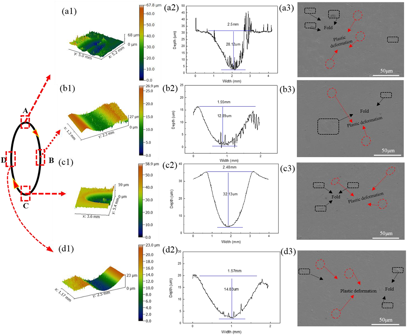
Wear morphologies of the XLPE surface at special point regions.
Column 1 is the three-dimensional morphology; column 2 is of the wear profile; column 3 is the SEM micrograph; region A and C are long-axis endpoint regions of the elliptical wear path; region B and D are the short-axis endpoint regions of the elliptical wear path.
Discussion
The spatial geometric effect model of friction proposed by Alison indicated that the friction and wear behavior in a multidirectional motion path is closely related to the cross-shear angle. 14 This paper seeks to understand the deformation and damage mechanism of XLPE under an elliptical motion path. As shown in Figure 1, under the action of a load and an elliptical motion path, XLPE is mainly subjected to the normal force, Fn, the centripetal force, Fr, and the tangential force, Fv, and the size and direction of the Fv and the Fr change with the location point. The damage mechanism of XLPE is mainly plastic deformation (Figures 7 and 14), because XLPE with a three-dimensional network structure has higher viscoelasticity and wear resistance21,22 along the crossing shear stress in an elliptical motion path. As seen from Figure 15, the deformation mechanism of XLPE is different under different forces. The three-dimensional network structure of XLPE can be simplified as an intertwined lamellar structure formed by isotropic crystalline lamellar layers entangled with anisotropic molecular chains 25 (Figure 15(a)). Generally, the deformation modes within the layers are divided into the following three types: interlaminar shear, layered lamination rotation and layer separation.26–28 Under normal loading and reciprocating linear sliding, the surface of XLPE bears normal compression deformation by normal loading, and the interlaminar shear occurs in the lamellar structure, resulting the molecular chains producing plastic flow in the shear direction and being stretched horizontally and compressed in the normal direction. Under the action of tangential force, the lamellar structure undergoes interlaminar shear, the molecular chain undergoes plastic flow in the shear direction, and the molecular chain undergoes transverse tensile deformation and normal compression deformation to a certain extent. The deformation degree of the near surface structure is greater than that of the internal structure (Figure 15(b)). Under normal loading and multidirectional elliptical path sliding, due to the changes of the centripetal force, Fr, and the velocity vector, the laminar structure of XLPE is subjected to not only interlaminar shear and compression, but also laminar rotation and laminar separation to various degrees. Meanwhile, the fluidity of the molecular chains increases, but the compression deformation of the molecular chains decreases (Figure 15(c)). Moreover, the rotation angle and separation degree between the plates are mainly affected by the curvature radius of the elliptical path.
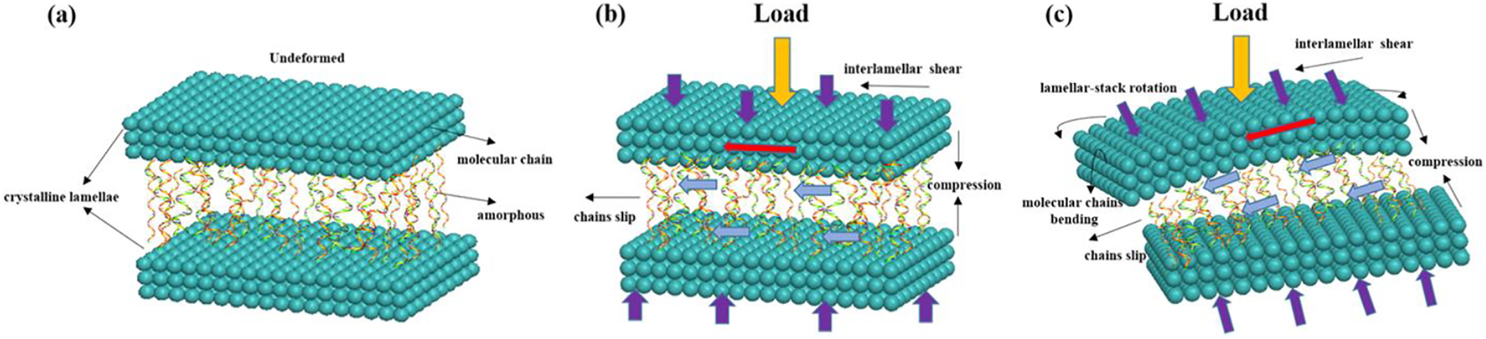
Schematic diagram of the XLPE deformation mechanism: (a) unloading; (b) under normal loading and reciprocating linear sliding; and (c) under normal loading and multidirectional elliptical path sliding.
As presented schematically in Figure 16, the cross-shear angle (α), affected by the interlayer rotation and separation of XLPE, is defined as the angle between the velocity vector of a differential surface element and the predominant sliding direction
14
(Figure 16(a)). Figure 16(b) shows the variation of the cross-shear angle α along a single-cycle motion path at different
Combining the results of the friction coefficient and wear morphologies analysis under different
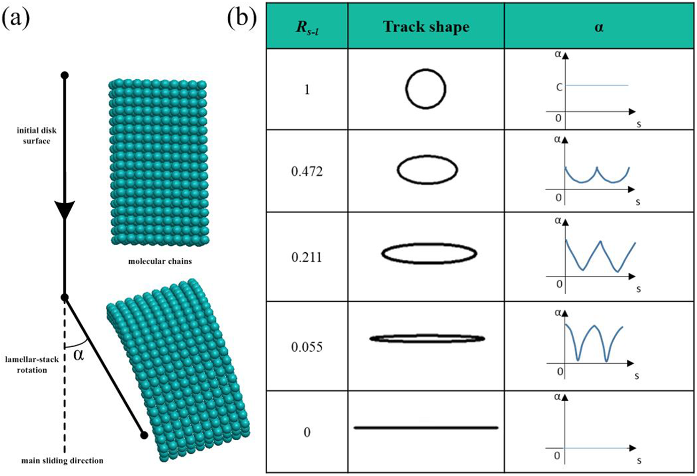
The variation of the cross-shear angle α along a single-cycle motion path at different
The periodic analysis of the friction coefficient of multidirectional motion path indicates that the friction coefficient curve shows obvious “W” periodic variation, and the “W” friction coefficient curve clearly corresponds to the motion path—there are maximum friction coefficients at the long-axis endpoints and minimum values at the short-axis endpoints (Figure 11). The wear morphologies of different characteristic positions on the surface of XLPE are also related to the motion path. The material accumulation caused by plastic flow at the long-axis endpoints is more serious than that at the short-axis endpoints (Figure 14), and the wear depths and widths at the long-axis endpoints are larger than those at the short-axis endpoints (Figure 14). This is due to the differences in the curvature radius, the velocity vector direction, the curvature radius change rate and the velocity direction change rate at different positions of the elliptical path. Figure 17 shows the deformation mechanism of XLPE at different characteristic positions of the elliptical path. At the long-axis endpoints of the ellipse (Figure 17(a), (c)), the curvature radius is smaller, the rotation angle and separation range of the XLPE laminate structure are larger, the cross-shear angle is larger, and the corresponding curvature radius change rate, velocity vector change rate and cross-shear angle change rate are larger. Therefore, in the predominant sliding direction, molecular chains are elongated, and the ability to prevent wear is inhibited. In the direction perpendicular to the predominant sliding direction, due to the large curvature radius change rate and velocity vector change rate, the ability to destroy the cross-linking of materials is enhanced, the ability to rearrange the material components and recover plastic deformation is weakened, the response is delayed, the friction coefficient is larger, and the wear is intensified, producing a deeper wear depth and a larger wear width.
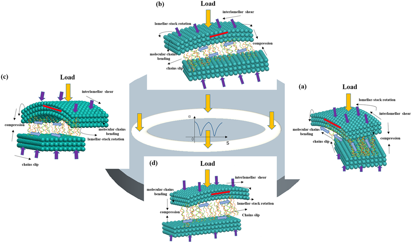
The deformation mechanism of XLPE at different characteristic positions of the elliptical path.
In terms of the wear morphology, CoCrMo and XLPE materials form a “hard-soft” contact. After loading, the XLPE with its softer hardness and high viscoelastic properties, can coordinate the tangential friction and reduce wear through elastic-plastic deformation. Therefore, the damage mechanism of the XLPE is mostly plastic deformation, and some multidirectional and cross-sectional scratches are caused by the cross-shear stress in the elliptical motion path (Figure 7(a) to (d)). In the reciprocating line motion path, since the material is not subjected to cross-shear and has a the single-direction slip velocity, the wear surface shows several deeper linear scratches in a parallel distribution (Figure 7(e)). Meanwhile, due to the high cross-shear effect, the XLPE components will undergo a certain degree of recovery and be recombined to hinder the wear; thus, the scratch depth of the elliptical motion path is obviously lower than that of the reciprocating line motion path. Since the CoCrMo, with its higher hardness, cannot compensate the wear damage through plastic deformation, some multidirectional and crossing scratches are produced under continuous extrusion and alternating shearing of the micro-protrusions or wear particles of the XLPE. Moreover, due to the different shapes of elliptical motion paths with different cross-shear actions on the materials, the smaller is the
Conclusion
The results of the testing provide a basic understanding of the effect of the multidirectional elliptical motion path on the wear of XLPE. A common belief concerning hip prosthesis wear is that the wear along a multidirectional motion path is obviously different from that along a reciprocating line path. The test results show that the friction coefficients and wear morphologies are highly affected by the cross-shear angle, based on the motion path. The friction coefficient decreases and the wear depth and width increase with the decrease in the
Footnotes
Funding
The author(s) disclosed receipt of the following financial support for the research, authorship, and/or publication of this article: This research is supported by the Fundamental Research Funds for the Central Universities (2017XKZD08) and a Project Funded by the Priority Academic Program Development of Jiangsu Higher Education Institutions (PAPD).