
Abstract
Cellulose microfibers were successfully fabricated from Vietnamese Nipa palm by mechanical and chemical treatments. The Nipa palm petioles were simply rolled, pressed, and separated. They were then pretreated with an alkaline solution and submitted to acid hydrolysis to remove the impurities (tCell). The microfibers were reinforced with reduced graphene oxide to form a hybrid that was reduced with hydrazine hydrate in the last stage (tCell-rGO). The structure and properties of tCell and tCell-rGO were evaluated by FTIR, XRD, DSC, TGA, SEM, BET, and the sheet resistance. It was observed that the treated cellulose microfibers exhibited a diameter of 10–20 μm and had good crystallinity in the structure. Both tCell and tCell-rGO exhibited low-density values of 1.52 kg/m3 and 0.58 kg/m3, respectively, and had good specific surface area values of 11.2 m2/g and 13.0 m2/g, respectively. These results supported the decrease in the density and the increase in the specific surface area of the tCell-rGO samples in comparison with the tCell. The existence of rGO sheets in the cellulose microfiber matrix resulted in changes in the structure, arrangement, and crystallization of pristine microfibers. The thermal property and electrical conductivity of the reinforced GO cellulose microfibers were significantly improved. rGO not only showed its role as a surface modification agent that helps the cellulose microfibers disperse better in the non-polar substrate, but also contributed to the increase of the heat-stable and mechanical properties of polymer. The thermal stability of tCell-rGO/PMMA composite was notably improved more than 40°C in maximum decomposition temperature by an emulsion polymerization technique. The material based on cellulose microfibers from the Vietnamese Nipa palm tree and reduced graphene oxide overcame some disadvantages such as the poor heat resistance, poor dispersion of the original fibers in the non-polar polymer and displayed great potential for environmentally friendly future applications.
Introduction
Currently, the development of society promotes the development of the polymer industry because most kinds of polymers are more easily produced than other materials. However, the greatest disadvantage of most polymers is their inability to biodegrade or their difficultly in degrading under natural conditions. This disadvantage has seriously affected environmental issues and land degradation. Many studies have solved this problem by blending nonbiodegradable polymers with natural ingredients that are completely biodegradable and based on CO2, H2O and biomass such as cellulose,1–3 starch,4–6 chitosan,7,8 or biodegradable polymers (polylactic acid,9,10 polyglycolic, 11 polyvinyl alcohol 12 ).
The parts of Vietnamese Nipa palm trees (Nipa fruiticans) such as the leaves, fruits, and body are optimal for construction, food, or fuel use. In particular, the petioles of leaves are often dried to prepare coal or are even thrown away. This is a huge waste because the petioles of the water coconut trees contain a large amount of cellulose (over 35%). 13 Extracting and using this cellulose resource as a reinforcing phase for nonbiodegradable polymers has effectively improved environmental problems.14–17
Cellulose is a major polysaccharide of plant cells, a biological polymer, and a linear homopolymer of β-D-glucose-pyranose, which is linked together by β-1,4-glucoside links. Networks of cellulose molecules are biodegradable by acid or alkaline agents, and they are an attractive food source for many kinds of fungi and bacteria in soil. Cellulose, as a popular bioingredient, has been used in composite materials in recent years. Cellulose is also known as a good adsorbent, and cellulose and its derivatives are widely used in water treatment and oil adsorbents due to their polar structure, which contains high intermolecular hydrogen bonding. The cellulose molecules can have a water-holding capacity and form water channels through their wide dimension.18–20 After cellulose is freeze-dried, these channels easily leave capillaries and large pores in the structure, which decreases the density of cellulose. However, the structure of these capillaries is often unstable and easily destroyed, and the density of the resulting porous cellulose materials is not light enough for a wide range of applications. Furthermore, cellulose is not easily compatible with non-polar polymer matrix composites. Moreover, the existence of many oxygen-containing functional groups on the surface also gives cellulose a low thermal stability (approximately 200°C).21,22 It is difficult to prepare a composite of cellulose with some kinds of polymers by melt processing. To obtain cellulose, plant fibers must initially be treated by chemical and mechanical methods to remove lignin and hemicellulose and the resulting cellulose fibers will be in micro or nanometer size. These treatments get many defects on the surface of the cellulose fibers and easily break cellulose crystals, so cellulose will often have low thermal stability. In order to prepare composite materials by melt processing, the processing temperature must be approximately at the melting point of the matrix polymer, then the polymer will flow and mix well with the reinforcing phase. Cellulose cannot melt but decomposes when it is mixed with polymers that have high processing temperatures above 180°C, such as poly(methyl methacrylate), nylon 6, polystyrene, poly(ether ketone). Therefore, this is also considered to be a limitation in selecting the preparation methods with cellulose-based composites.
In simple terms, reduced graphene oxide (rGO) is obtained from the reduction of graphene oxide sheets by thermal, chemical, or electrical treatment. As with graphene, rGO is a thin layer or is formed by a few thin layers of pure carbon; it is a single layer of tightly packed layers of carbon atoms, which are bonded together in a hexagonal honeycomb lattice. rGO has a structure that is similar to that of graphene, so rGO is considered to have the properties of graphene with many prominent properties, such as a high thermal stability, good electrical conductivity, lofty mechanical properties, and transparency. 23 rGO is also one of the popular nano-reinforcing phases for polymers. rGO also has a hydrophobic surface, therefore the surface of cellulose microfiber reinforced with rGO disperses well in non-polar solvents or matrix polymers. 24 In this study, cellulose microfibers were modified with rGO in an effort to improve the reinforcing capability of cellulose microfibers from the Vietnamese Nipa palm trees in polymer composites and to enhance other properties such as the thermal stability, electrical conductivity, and mechanical properties. It also contributes to making the structure of cellulose-based absorbents more stable and lighter. This process has been able to improve some disadvantages of the original cellulose to extend its applications in the preparation of environmentally friendly polymer composites.25–27
Polymethyl methacrylate (PMMA) is known as a non-polar polymer with high processing temperature, high hardness, chemical resistance, and good thermal stability, so it is widely applied in life. 28 The addition of an ingredient such as cellulose has been reported by Sain et al. 29 for the biodegradability improvement of PMMA. However, the reinforcement with a hydrophilic and weak heat-stable component as cellulose is always a problem for the dispersion and thermal stability of a hydrophobic polymer like PMMA. Cellulose in nanometer-sized form has been introduced as a bio-reinforcement phase for PMMA by emulsion polymerization without using a compatibilizer. The obtained cellulose/PMMA composite showed the decreases in value of the glass transition temperature and of the maximum decomposition temperature. 30 The acetone blending method is another one used to fabricate commercial cellulose nanofiber/PMMA composite with the mix ratio of nanofibers less than 0.5 wt% showing the improvements in flexural and storage modulus values. 31 Most studies have put the ratio of reinforced cellulose at low ratio below 3 wt%. At the low cellulose content, the improvement in bio-decomposition for PMMA will be worse than that of composite with higher cellulose content.29,32 Hence it is necessary to use a compatible auxiliary to be able to introduce cellulose with a greater mass ratio. The addition of rGO plays the role as a compatibilizer for the cellulose that can be seen as a new way to fabricate PMMA composite with high loading of cellulose microfiber. The resulted bio-based composite with a high tCell-rGO ratio can continue to be used as a masterbatch for the melt processing option. Cellulose microfiber reinforced by reduced graphene oxide has been expected to improve the thermal and mechanical properties of cellulose/PMMA composite and be a material that could further improve the preparation eco-friendly green PMMA composite.
Materials and methods
Materials
Nipa palm leaves were harvested from Nha Be district, Ho Chi Minh, Vietnam. Hydrazine monohydrate was supplied by Merck, Singapore. Purified flakes of graphite (SNO-30) were purchased from SEC Carbon Company, Japan. Potassium permanganate, sodium nitrate, hydrogen peroxide solution (30%), absolute ethanol, sodium hydroxide, concentrated sulfuric acid solution, sodium hydrosulfite, sodium dodecyl sulfate, sodium persulfate, and sodium hypochlorite solution (35%) were purchased from Guangdong Guanghua Sci-Tech Company, China. Methyl methacrylate monomer (Merck, Darmstadt, Germany) was used after distillation. Deionized water was used in all experiments.
Synthesis of graphite oxide
Graphite oxide was synthesized from graphite using the Hummers method33,34 with a combination of strong oxidizing agents such as H2SO4, NaNO3, and KMnO4. Briefly, graphite (0.50 g) was mixed with concentrated sulfuric acid (23.0 ml) for 20 min at 0°C; then, NaNO3 (0.50 g) was added and stirred for 1 h. KMnO4 (3.00 g) was added while the mixture was kept at 0°C. After that, the mixture was subsequently heated to 35°C for 1 h, water (40.0 ml) was added to the mixture, and the flask was then heated to 90°C for 30 min. Additional water (100.0 ml) was added to the stirred mixture, and then H2O2 (10.0 ml, 30 vol%) was added dropwise to the flask. The suspension was precipitated and neutralized until the pH was approximately 7 by centrifuging with water several times. The precipitated product was dried in a vacuum at 65°C for 24 h to obtain graphite oxide (GO).
Chemical treatment of Nipa palm fibers
In the first step, the petioles of Nipa palm trees were removed from the shells and cut into pieces with dimensions of 30 cm × 1 cm (length × thick). Then, these samples were dried for 4–6 h under sunlight after they were laminated by a two-axis roller. The resulting samples were soaked in a 10.0% NaOH solution for 1 h at room temperature and neutralized with a solution of 1% acetic acid and deionized water several times.
In the second step, the obtained Nipa palm fibers were milled into lengths of 500–700 µm. Approximately 1.0 g of fibers was added to a three-neck flask containing 10.00 mL of a solution of 5% NaOH at 60°C. After 2 h, these fibers were neutralized with distilled water several times. Then, the fibers were added to a 5.0% NaClO solution in a flask to bleach them at a temperature of 60–70°C for 2 h. 35 The bleached fibers were washed several times with distilled water again until the pH was approximately 7. Then, the fibers were added to the flask and cooled in an ice bath. After that, 9.09 ml of a solution of sulfuric acid (60%) was added slowly to the flask and then heated to 45°C for approximately 1.5 h. Finally, the slurry containing Nipa palm fibers was centrifuged several times with distilled water until the pH was approximately 7 and then dried in a vacuum oven at 65°C for 24.0 h. The last collected fiber powder is called tCell.
Reinforcement of treated Nipa palm fiber by reduced graphene oxide
Approximately 0.10 g of GO was dispersed into 500.0 ml of water in an ultrasonic bath at ambient temperature for 1 h. Approximately 0.90 g of hydrolyzed fiber and 49.0 ml of water were then added to the above suspension and stirred for 5 h to obtain a homogeneous dispersion of tCell-GO. The resulting mixture was refluxed at room temperature for 30 min under a nitrogen atmosphere and a controlled pH of 8–9. Then, 20.0 ml of hydrazine hydrate was added, and the reaction mixture was refluxed at 95°C for 4 h. 36 During this reaction, tCell-GO was reduced by hydrazine to tCell-rGO. The obtained mixture was cooled to room temperature and then neutralized by a solution of HCl (5.0%) and distilled water several times.
Preparation of tCell-rGO/PMMA composite by emulsion polymerization
1.80 g of sodium dodecyl sulfate was completely dissolved in 90 ml distilled water and placed into a round-bottom flask equipped with a mechanical stirrer, a dropping funnel, and a condenser with a nitrogen inlet. 0.25 g of tCell-rGO was added and the suspension was stirred for 10–12 h and ultrasounded for 45 min. The suspension was then kept in an ice bath, 2.25 g of methyl methacrylate monomer was added dropwise to the reaction vessel. After addition, the reaction temperature was increased to 60°C. Then, a mixture of 22.5 mg Na2S2O8 and 2.25 mg NaHSO3 was added into the flask and the reaction was refluxed for 6 h at 80°C. The reaction mixture was then allowed to warm to room temperature and was isolated by using solvent methanol to precipitate to obtain a solid. The solid was filtered and washed three times with distilled water to remove impurities and unreacted monomer. The solid was then dried and finely ground to give a product, namely, tCell-rGO/PMMA. The same synthesis method as above was adopted to synthesize neat PMMA and tCell/PMMA.
Characterizations
Fourier transform infrared (FTIR, Tenser 27-Bruker-Germany) experiments of Cell, tCell, and tCell-rGO with a wavenumber range of 400 and 4000 cm−1 (KBr disk) were performed.
The X-ray diffraction (XRD, D8-ADVANCE) patterns of Cell, tCell, and tCell-rGO were recorded in the rough range of 2θ angles from 5° to 40° to characterize the crystallinity in the structure, with a step size of 0.03° and a dwell time of 2 s.
The film resistance values of tCell and tCell-rGO were recorded using a two-point probe connected with a digital multimeter tester (KYORITSU, 1009), with a thickness of 130 μm.
SEM images of tCell and tCell-rGO were obtained using a field-emission scanning electron microscope FE-SEM Hitachi S4800 at an acceleration voltage of 10 kV.
Specific surface areas of tCell and tCell-rGO were measured by using the BET method based on the nitrogen adsorption/desorption isotherm (NOVA 3200e, Quantachrome) at liquid nitrogen temperature.
Thermogravimetric analysis (TGA) of Cell, tCell, tCell-rGO, PMMA, tCell/PMMA, and tCell-rGO/PMMA were performed using a thermobalance Q500 V20.13-Build 39 from room temperature to 800°C, at a heating rate of 10°C/min in a continuous nitrogen flow.
Differential scanning calorimetry (DSC, Columbus, Ohio, USA) was performed with a METTLER STARe SW 11.00 instrument. rGO, Cell, tCell, tCell-rGO, PMMA, tCell/PMMA, and tCell-rGO/PMMA were measured from room temperature to 200°C, at a heating rate of 10°C/min in a nitrogen atmosphere.
The molecular weight of the neat PMMA and tCell-rGO/PMMA was performed using a Gel permeation chromatography (GPC) (YOUNG IN Chromass, YL9100 GPC) at a rate of 1.00 ml/min at room temperature. Tetrahydrofuran (THF) is used as a solvent.
The mechanical properties of neat PMMA and tCell-rGO/PMMA were carried out on Dynamic mechanical analysis (DMA, VR 7130, Ueshima Seisakusho, Japan) from 40 to 200°C under air at a frequency of 1 Hz with 0.01% deformation. The bars (65 × 13 × 2 mm3) were prepared by heat-pressed at 210°C for 10 min from powder samples of the emulsions polymerization.
Results and discussion
Characterizations of Nipa palm fibers after treatment and reinforcement
The color of the Nipa palm fibers changed from a light color to a dark color after the treatment and reinforcement, as shown in Figure 1. The color of pure cellulose fibers containing lignin and hemicellulose is dark yellow, but it is a yellowish color after being treated by NaOH, NaClO, and H2SO4. In the last step, the color of tCell-rGO is black due to the presence of reinforced rGO.
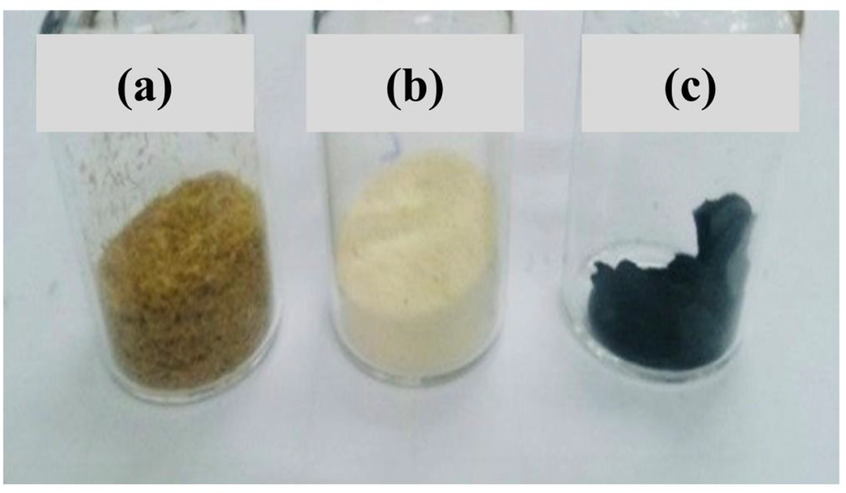
Digital image of Cell (a), tCell (b), and tCell-rGO (c).
The chemical structure of cellulose after the treatment and reinforcement was analyzed by FTIR (Figure 2). In pure cellulose fibers, the peaks at 3412, 2930, 1640, 1400, and 1052 cm−1 are assigned to the vibration of O-H, C-H stretching, O-H of water absorbed by cellulose, CH2 symmetric bending, and C-O stretching, respectively. The peaks at 1632–1609, 1509, and 1247 cm−1 are indicated as the vibration of -C=C-, C-C stretching of benzene rings, and O-CH3 groups of lignin, respectively. The peak at 1738 cm−1 is a characteristic vibration of C=O stretching belonging to the carboxylic groups and methyl ester groups of hemicellulose. There is a modification in the structure of Nipa palm microfibers after treatment and reinforcement. After the three-stage treatment, the peaks at 1738 cm−1 and 1509 cm−1 completely disappear, and there is a sharp decrease in the band at 1247 cm−1. The results indicate that most of the hemicellulose and lignin components in the Nipa palm fibers are removed by using the combination of chemical and mechanical treatments, the amorphous region of lignin disappears, and therefore, the mechanical properties of the Nipa palm fiber are improved.
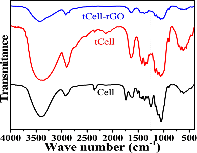
FT-IR spectra of Cell, tCell, and tCell-rGO.
The FTIR spectrum of reduced grapheme oxide-reinforced cellulose microfibers, tCell-rGO, is the same as the FTIR spectrum of tCell, but the band at 3400 cm−1 (the O-H stretching) is not sharper and weaker than that of tCell. Consequently, the hydrogen-bonded interaction between the hydroxyl groups of cellulose and the carboxyl or hydroxyl groups of graphene oxide sheets is significantly decreased.37–39
The crystalline structure of the Nipa palm fibers after treatment was studied using the X-ray diffraction patterns (Figure 3). Untreated, treated, and reinforced Nipa palm fibers with two main reflection peaks are observed at 2θ = 16° and 22.5°, which are related to the crystalline structure of cellulose. According to Qingzheng Cheng et al. 40 , the crystallinity region of cellulose crystals is demonstrated by the peaks at the 2θ angle of 22.5° and 16°, corresponding to planes (002) and (110), respectively. There is almost no change in the XRD patterns between the original fiber, the treated microfiber, and the reduced graphene oxide-reinforced cellulose microfiber.
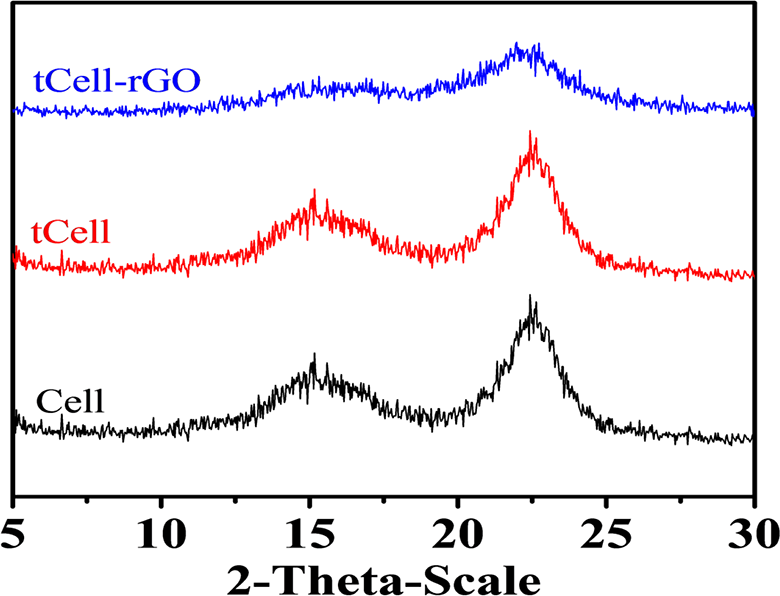
X-ray diffraction patterns of Cell, tCell, and tCell-rGO.
Table 1 shows the crystallinity of Cell, tCell, and tCell-rGO. The crystalline index of cellulose and CIr are represented by the following equation (1) 41 :

where I002 is the intensity of lattice peak diffraction with a diffraction angle 2θ of approximately 22.5°, the peak for the plane (002). Iam is the peak intensity of the amorphous fraction with the lowest intensity at a diffraction angle 2θ of around 18°.
The crystallinity of Cell, tCell, and tCell-rGO.
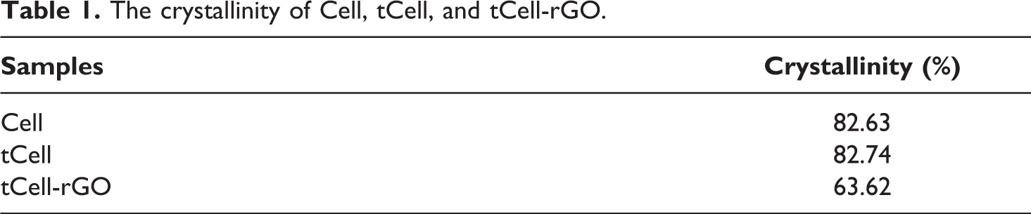
These results show that the crystallization of tCell shows almost no change (82.0%) after the treatment process. This confirms that the chemical treatment of the Nipa palm microfibers only removes lignin and hemicellulose and almost does not affect the structure of the original cellulose fibers. Therefore, the structure and crystallinity of tCell are not changed, while the crystallinity of tCell-rGO decreases by approximately 20.0% with the addition of rGO. The interactions of reduced graphene oxide sheets on cellulose microfibers interfere with the arrangement of the cellulose molecules. Therefore, the crystallinity of the cellulose decreases.42–44
SEM images (Figure 4) show the surface morphology and diameter of the Nipa palm fibers (Figure 4(a)) before and after treatment. The results indicate that the tCell fibers have average diameters ranging from 14 µm to 20 µm and average lengths ranging from 300 µm to 500 µm (Figure 4(b)). The ratio of the length and diameter of the fibers is approximately 15–30. Moreover, the microfibers are cleaner and have a rougher surface than those of untreated Nipa palm fibers (Figure 4(c)). This result is the same as what was described in the reports of Yadav M et al. 45 and Sosiati H et al. 46
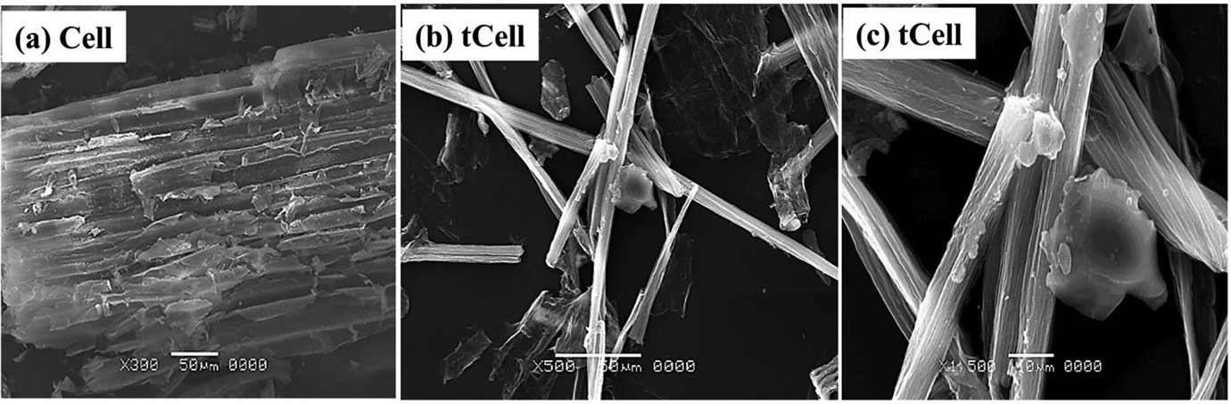
SEM images of Cell and tCell at 500× and 1500× magnifications.
The adsorption ability of two kinds of microfibers after freeze-drying was analyzed by using the BET adsorption isotherm and Langmuir isotherm plots. Both tCell and tCell-rGO exhibit low-density values of 1.52 kg/m3 and 0.58 kg/m3, respectively, and have good specific surface area values of 11.2 m2/g and 13.0 m2/g, respectively. The presence of rGO sheets on cellulose microfibers makes the structure of the microfibers more porous. As shown in Figure 5(a) and (b), the equilibrium data of nitrogen adsorption on tCell and tCell-rGO apply to fit the line to the BET adsorption isotherm. Furthermore, the equilibrium data of tCell are linear in the Langmuir isotherm plot (Figure 6(a)). These results show that the monolayer adsorption ability is suitable for the tCell adsorption model. Otherwise, the equilibrium data of tCell-rGO are not linear in the Langmuir isotherm plot (Figure 6(b)). The Langmuir isotherm is unlikely to predict the N2 equilibrium data correctly, and the other isotherm such as the Langmuir-Freundlich isotherm can be more suitable to presage the multilayer adsorption capability of tCell-rGO.
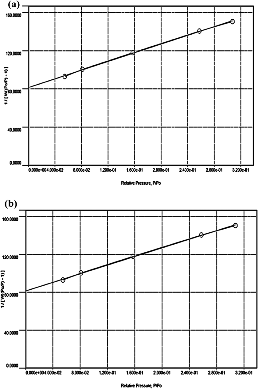
Plots of the BET adsorption isotherm for nitrogen on tCell (a) and tCell-rGO (b) at -195.65°C.
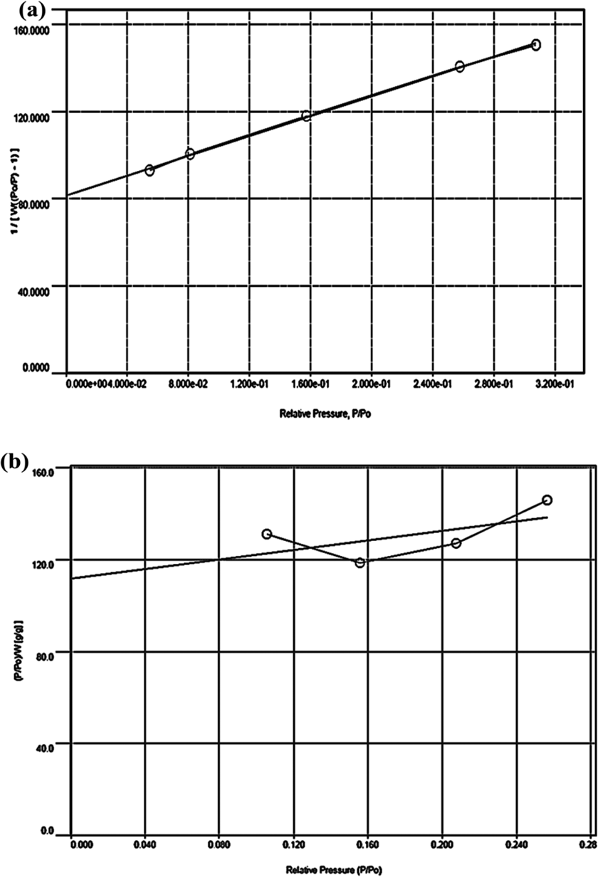
Plots of the Langmuir adsorption isotherm for nitrogen on tCell (a) and tCell-rGO (b) at -195.65°C.
Figure 7 shows the random arrangement in the nonordered structure of cellulose microfibers with many gaps to create a network of a porous 3D material. SEM images also indicate the change in the structure of cellulose microfibers in which there is the incorporation of reduced graphene oxide sheets. Although the cellulose microfibers are randomly sorted on the surface of the sample (Figure 7(c)), they exist in a parallel-layer structure with a large gap between two layers (≈100 µm) along the thickness of the sample (Figure 7(d)). The presence of the reduced graphene oxide nanosheets affects the structure of the cellulose microfibers. 47 This result supports the decrease in the density under the same conditions and the increase in the specific surface area of the tCell-rGO samples in comparison with the pristine cellulose microfiber tCell (Figures 7(a) and (b)).
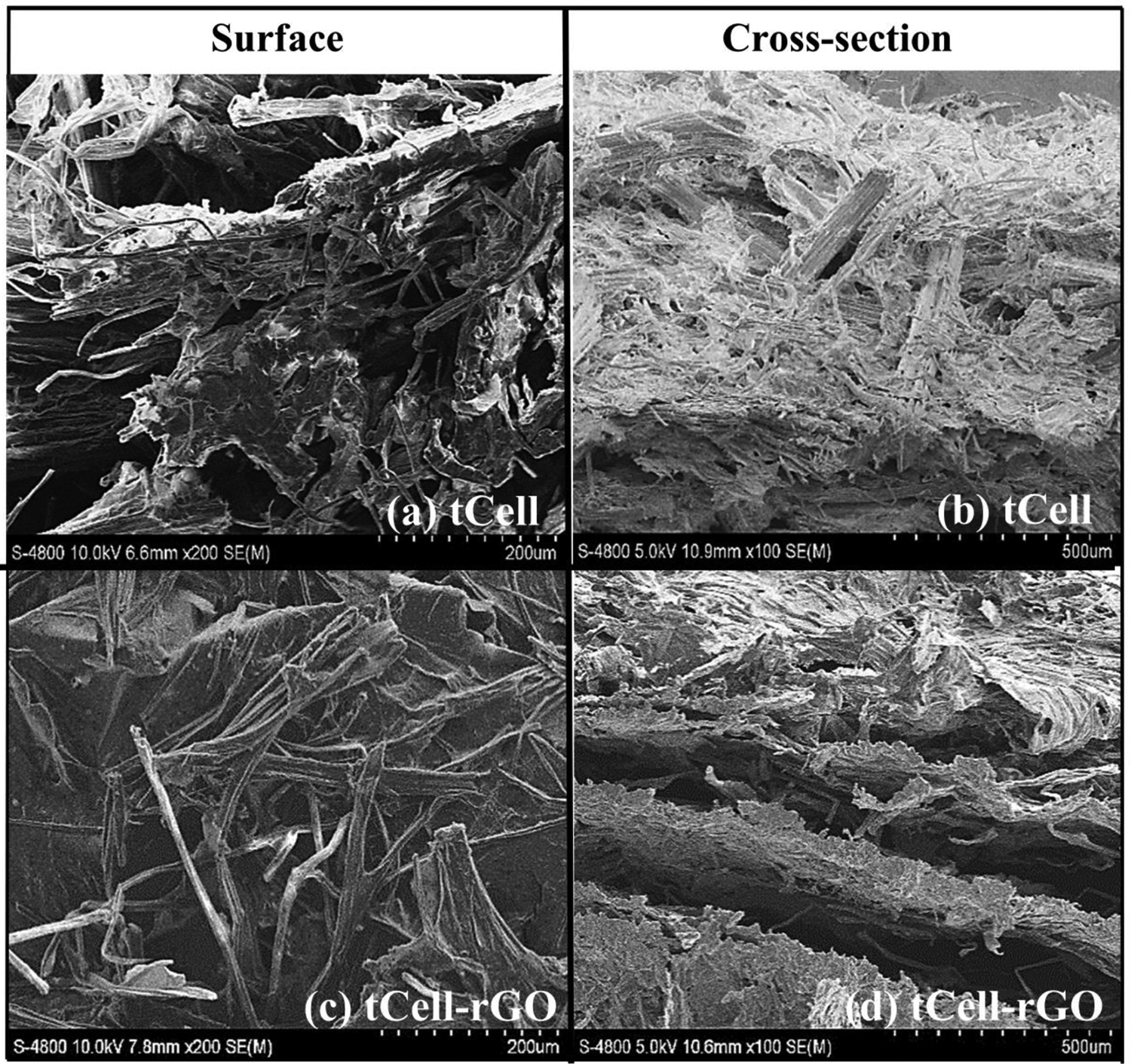
SEM surface and cross section images of (a, b) tCell and (c, d) tCell-rGO.
Thermal property of Nipa palm fibers after treatment and reinforcement
Figures 8 and 9 show three regions of the thermal decomposition of Cell, tCell, and tCell-rGO (regions I, II, and III). In the first decomposition region below 200°C, the weights of the raw and treated fibers slightly decrease due to the removal of volatiles as water (1–3 wt% in region I). The TGA curve of tCell-rGO has a weight loss of approximately 5 wt%, which is related to the desorption of water and CO2 on the surface of the reduced graphene oxide in this temperature range.48,49
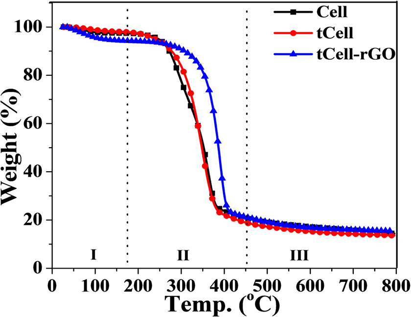
TGA curves of Cell, tCell, and tCell-rGO.
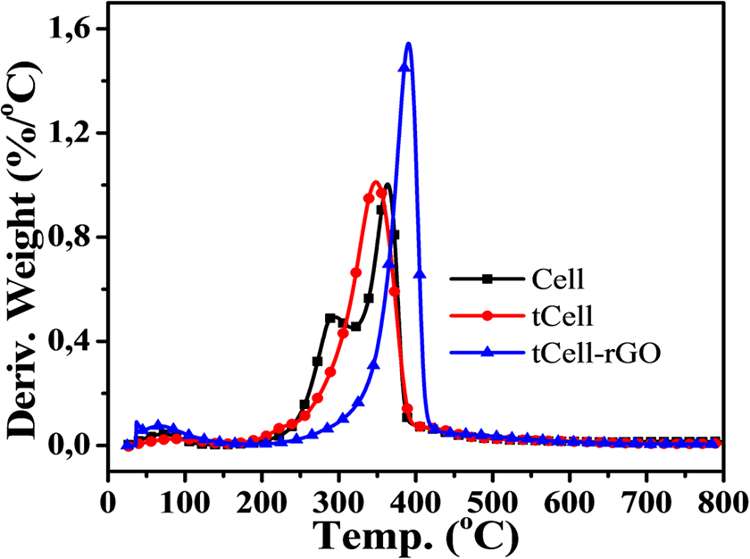
DTG curves of Cell, tCell, and tCell-rGO.
In the second region, Cell exhibits two maximum decomposition peaks at 290 and 360°C in the DTG curve (Figure 9), which indicate the thermal decomposition of compounds in the Nipa palm fiber such as cellulose, hemicellulose, and lignin. Meanwhile, the DTG curve of tCell has a narrower weight loss and one maximum peak at 350°C, related to the deconvolution of α-cellulose in microfibers (region II). 2 This is due to the removal of the lignin and hemicellulose components from the Nipa palm fibers after treatment. tCell-rGO shows the most thermostable sample with an onset temperature at 344°C and a maximum decomposition peak at 390°C. The presence of the reduced graphene oxide sheets in the cellulose matrix plays a role as a protective layer and improves the thermostability of the cellulose microfiber matrix. The mass loss of tCell-rGO in this region is similar to that of tCell (approximately 75 wt%) and is related to the decomposition of α-cellulose, and the 25 wt% weight loss is the decomposition of the remaining functional groups on the rGO sheets. According to Mariano M., the third region (region III) is the oxidation of residual coal. 50 Both TGA curves of the three samples Cell, tCell, and tCell-rGO have an 18 wt% residual char.
The presence of the reduced graphene oxide nanosheets in tCell-rGO was also studied by DSC analysis (Figure 10). The DSC curve of the raw Nipa palm fibers shows a large endothermic peak from 80°C to 180°C, while there is a sharp endothermic peak in the DSC curve of the treated microfibers from 150°C to 180°C. As a result, the effectiveness of the combination of mechanical separation and chemical treatment in the three-step treatment removes a large amount of the amorphous component in the structure of the Nipa palm fibers to increase the order in the crystalline structure of the cellulose fibers. In addition, the DSC curve of the treated Nipa palm fibers reinforced by the reduced graphene oxide is similar to the appearance of only a melting peak for the cellulose crystalline in the lower temperature range between 140 and 180°C for the treated microfibers. Conversely, the reduced graphene oxide does not obtain any exothermic or endothermic signals from room temperature to 200°C, so there is no peak of rGO in the DSC curve of tCell.
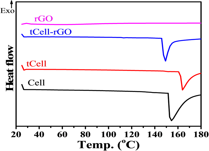
DSC curves of Cell, tCell, and tCell-rGO.
Sheet resistance of reinforced Nipa palm fibers with reduced graphene oxide
Table 2 shows the sheet resistance (Rs) of tCell and tCell-rGO films calculated from the film resistance values of a two-point probe tester (

where Rs is the sheet resistance of the film (in Ω/sq); the resistivity of the film is
Results of the surface resistivity of tCell and tCell-rGO.
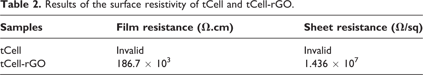
The sheet resistance is used to clearly demonstrate the interaction between the rGO and the cellulose microfibers after the reinforcement from the film resistance value with a two-point probe tester. Nipa palm cellulose microfibers are completely nonconductive, so the film resistance value cannot be recorded. The conductivity of reinforced microfibers significantly improved through the recognition of the sheet resistance value with the presence of reduced graphene oxide sheets. However, this resistivity value is very high, and it needs more improvements to be applicable.
Molecular weight of neat PMMA and composites
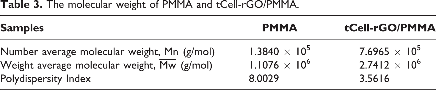
Table 3 shows the results of the molecular weight of neat PMMA and tCell-rGO/PMMA composite. In general, the composite has a higher molecular weight and smaller polydispersity than those of neat PMMA. In situ polymerization by emulsion occurs under the free radical mechanism, the presence of reinforcement such as tCell-rGO contributed to protecting the active centers on the polymer chains in the reactions. The longer life span of these active centers was prolonged, so the molecular weights of polymer increased and polydispersity reduced. 52
The molecular weight of PMMA and tCell-rGO/PMMA.
Thermal property of neat PMMA, tCell/PMMA, and tCell-rGO/PMMA composites
Figures 11 and 12 show the thermal stability of tCell-rGO, PMMA, tCell/PMMA, and tCell-rGO/PMMA. tCell/PMMA has two regions of thermal degradation. The first degradation step lost 20 wt% in the temperature range of 200–370°C. This is considered to be due to the degradation of the cellulose microfibers in tCell/PMMA composite. Since tCell and PMMA are different in polarity, the cellulose microfibers tend to conglomerate to form phase separations in the composite. Consequently, these regions are easily affected by heat that reduces the thermal stability of the composite. This result is also mentioned in the report of Sain S et al. 53 The second decomposition step of tCell/PMMA takes place immediately after the first stage and ends at 480°C, with the maximum decomposition peak approximately at 406°C. The maximum decomposition temperature of tCell/PMMA is much higher than that of neat PMMA. This result can be explained by the formation of a protective shield of decomposed cellulose microfiber into carbon, which improves the heat-stable of polymer chains during this period. However, the shielding effect is not significant due to the phase-separated state of microfibers in the polymer matrix.
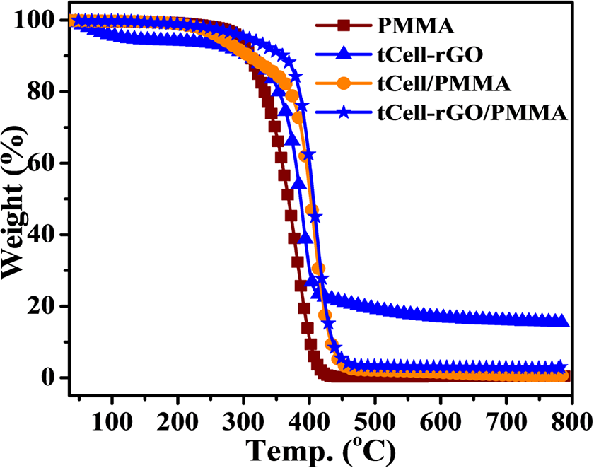
TGA curves of tCell-rGO, PMMA, tCell/PMMA, and tCell-rGO/PMMA.
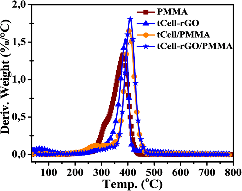
DTG curves of tCell-rGO, PMMA, tCell/PMMA, and tCell-rGO/PMMA.
The DTG curves of PMMA and tCell-rGO/PMMA show one main stage of the thermal decomposition (Figure 12). PMMA has an onset temperature at 350°C, being lower about 30°C than that of tCell-rGO/PMMA composite. The maximum decomposition peaks are 381°C and 409°C for PMMA and tCell-rGO/PMMA, respectively. The higher thermal stability of tCell-rGO/PMMA is explained by the presence of tCell-rGO. Furthermore, cellulose microfibers reinforced by rGO have better dispersion into the non-polar polymer PMMA, so it improves the thermal stability of the tCell-rGO/ PMMA composite. This result indicates the role of rGO is not only a reinforcement but also a surface modification agent in the dispersion of cellulose microfibers in non-polar matrix. 54 The reinforced cellulose microfibers also acted as a protective agent for the polymer chains under the external heat effect that helps heat transfer better on the polymer chains. From this result, it can be concluded that rGO not only improves the heat-stable of cellulose microfibers and tCell-rGO/PMMA composite, but also helps increase the compatibility of microfibers with PMMA matrix. This result is somewhat higher than the thermal stability of PMMA/TEMPO-oxidized cellulose nanofibers nanocomposite using amine-functionalized poly(ethylene glycol) as a surface modifying agent of Huang T et al. 32 Eco-friendly green PMMA/cellulose nanofiber nanocomposites with cellulose nanofibers modified by maleic anhydride 29 have obtained the same maximum decomposition temperatures as those obtained in this study.
The interaction between PMMA and reinforcement materials was also shown by DSC (Figure 13). The DSC curves showed that there was a different change of the glass transition temperature (Tg) of PMMA reinforced with tCell and tCell-rGO. The presence of rGO in the structure has increased the interaction of cellulose microfibers with polymer chains and made reduce movements of polymer molecular. Accordingly, Tg of tCell-rGO/PMMA has increased more than that of the neat PMMA by 6%. Meanwhile, tCell/PMMA composite has Tg lower by 5.5% than Tg of the neat PMMA because of the weak interaction between tCell and PMMA.
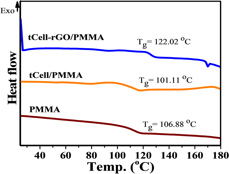
DSC curves of PMMA, tCell/PMMA, and tCell-rGO/PMMA.
Figure 14 shows the dynamic mechanical properties of PMMA and tCell-rGO/PMMA composite including the values of storage modulus, loss modulus, and tan delta. It is possible to evaluate the stiffness of PMMA after being reinforced with tCell-rGO via the storage modulus value of the materials. There is no difference between the storage modulus values of the two samples before the glass transition zone. The modulus of the composite also shows slight improvement after the glass transition zone (Figure 14(a)). The loss modulus value highlights the viscosity of the material. The increasing loss module shows an increased polymer structural mobility in the glass transition zone. Figure 14(b) indicates that the maximum value of loss modulus of composite is shifted to a higher temperature than that of the neat PMMA. This result is due to the addition of the reinforced phase, which increases the energy dispersion of the composite material by reducing the free volume in the material. 55 The peak value of the tan Delta curve is considered as the Tg value of the polymer. Figure 14(c) shows the Tg value of the composite sample shifting to a higher temperature than that of neat PMMA from 118.81 to 123.03°C. This result is similar to the results mentioned in the DSC (Figure 13) and it relates to an increase in the rigidity of the polymer chains due to the interaction between polymer chains with tCell-rGO reinforced phase.
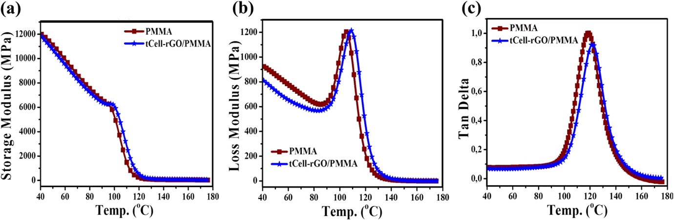
(a) Storage modulus, (b) loss modulus, and (c) tan delta curves of PMMA and tCell-rGO/PMMA.
Conclusions
Cellulose from the petioles of Vietnamese Nipa palm trees was separated and treated successfully by the three-stage treatments. This process, which includes alkaline bleaching and hydrolysis, removes lignin and hemicellulose to obtain pure exfoliated cellulose with an average fiber diameter of less than 20 microns. The existence of rGO sheets in the cellulose microfiber matrix impacts the changes in the structure, arrangement, and crystallization of pristine microfibers. The thermal property and the electrical conductivity of tCell-rGO were significantly improved. The thermal stability of tCell-rGO/PMMA composite was improved more than 40°C in maximum decomposition temperature. The glass transition temperature of PMMA was increased by 6% when PMMA was reinforced with tCell-rGO in both DSC and DMA. The presence of tCell-rGO improves the mechanical properties including the storage modulus, loss modulus, and tan delta. rGO not only shows its role as a surface modification agent that helps the cellulose microfibers disperse better in the non-polar substrate, but also contributes to the increase of the heat-stable of polymer. On the other hand, the presence of tCell-rGO also contributes to increasing the molecular weight and reducing the polydispersity of the matrix polymer in polymerization process. These results are promising for the next applications of cellulose microfiber material from Nipa palm tree.