
Abstract
Oven vacuum bag processing is an emerging process to manufacture high quality thermoplastic parts with void reduction using vacuum consolidation only. This paper models void air removal as a combination of through-the-thickness gas diffusion and in-plane airflow through the interlayer region for a flat plate of finite in-plane dimensions consisting of an arbitrary number of layers. A finite difference model assumes Fickian diffusion, simplifies the microstructure of the multi-layer prepreg stack and allows evaluation of various material and process conditions (inter- and intra-layer void content, temperature and pressure cycle, etc.) on the through-thickness diffusion behavior of the volatiles. In-plane airflow in the intra-layer is modeled using Darcy’s flow and requires high permeability of the interface created by the porous volume in between adjacent layers and the ability to vent the gas at the part edge. The dual mechanism model evaluates part geometries and processing cycles to reduce void content equivalent to autoclave parts with previously generated material properties of AS4/APC2 carbon PEEK prepreg. The modeling results based on the proposed mechanism shows that processing with through-the-thickness diffusion and standard processing cycles limits part thickness to five layers or less for APC2 while in-plane gas reduction can be used to make large parts of up to 10 m in the in-plane direction independent of part thickness. Very large parts require the addition of an intermediate lower temperature dwell cycle where diffusivity is high but interlayer permeability is unaffected allowing gas flow to the part edges for an extended period of time. The edge vent approach ensures a robust process even for as received materials with significant void variability often seen in thermoplastic prepreg tapes.
Introduction
Oven vacuum bag processing (OVB) can significantly reduce the manufacturing cost for high-performance thermoplastic composite materials compared to autoclave processing. The critical issue for OVB to achieve comparable mechanical performance of autoclave parts is void reduction using vacuum consolidation only. Removal of the inter- and intra-layer void volatiles from the part is the key to reduce void content during OVB while positive pressure processes increase polymer solubility allowing void volume reduction without gas transport out of the prepreg material. A mechanism for air removal in thermoplastic composites has been proposed by the authors in 1,2 Since the voids are fully encapsulated in the prepreg,3,4 air can diffuse from the voids in a single layer prepreg into the interlayer region formed between two prepreg layers, and then flows in-plane through the permeable interlayer region to the part perimeter to the vacuum, as illustrated in Figure 1 (a).
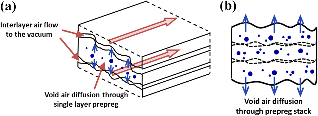
Schematic of void air removal mechanisms (a) void air diffusion through single layer prepreg followed by flow through permeable interlayer regions, (b) void air diffusion through the thickness direction of a prepreg stack.
These mechanisms allow void free (void content <1%) thin and thick-section thermoplastic composite laminates, comparable to high quality autoclave parts.1,2 Experimentally, the effect of part geometry and edged condition has been studied in 1 and shows that up to four layers of AS4/APC2 carbon PEEK prepreg with the standard consolidation cycle can be processed without any in-plane air removal while a thicker part exhibits high porosity. The time required for void air removal depends on the time for air diffusion through the single layer prepreg and flow time in the interlayer region. Air diffusing from the voids into the surrounding resin and interlayer surfaces of the prepreg is a highly transient process, and the diffusion time can largely depend on the processing conditions.1,5,6 The air evacuation time in the interlayer region is governed by the part in-plane sizes (flow length) and interlayer permeability.7–9 In order to achieve low void content, it is critical to increase the diffusion rate while maintaining the interlayer permeability from collapsing under vacuum pressure, and providing enough time for air flowing to the vacuum before resin melts during the OVB processing cycle. Interlayer air removal stops for high temperature cycles as interlayer permeability drops to zero as the interface between layers collapses. In this case and for thick laminates, the diffusion time may be substantially longer than the practical processing time. For thin parts with large dimensions, through-thickness diffusion mechanism as shown in Figure 1 (b) can be efficient. Thus, the processing cycle has to be designed considering tape properties and part geometry. Models based on the mechanism of void air removal are needed to provide in-depth understanding of the effects of processing conditions and part dimensions to minimize porosity, allowing the design and optimization of the processing cycle.
Void dynamic models involving gas diffusion and nucleation were developed by Amon and Denson 10 and Arefmanesh et al. 11 for bubble growth in viscous fluid in foaming process, Roychowdhury et al. 12 for volatile-induced void formation in PEI resin, and Ledru et al. 13 for void growth in the processing of thermosetting composite. In all these models, Fickian diffusion equation is used to describe the volatile diffusion process, and mass conservation equation at the void polymer or composite interface. Here, initial void content in the composite is assumed to be zero, but voids nucleate and are assumed to be spherical, which may not be suitable for the pre-existing rod-like voids in the thermoplastic prepreg.3,4 In addition, the isothermal condition of the models is not valid for standard OVB processing cycles. The gas flow mechanism in porous materials is well understood and can be described by Darcy’s Law.13–15 Characterization of the interlayer permeability and its change with processing is needed to capture the in-plane flow characteristics of OVB and can be used to evaluate the relevant evacuation time scales.
In this study, void air removal models based on air diffusion through the thickness of single layer prepreg as well as prepreg stacks, and air flow through interlayer region are developed. Material parameters of AS4/APC2 prepreg from previous studies are provided and standard temperature cycles are applied. The effect of initial void content and tape thickness in the raw prepreg tape as well as part thickness and in-plane dimensions are discussed in this paper. The design and optimization of the processing cycle is demonstrated and may require an intermediate dwell cycle to extend diffusion and in-plane flow times for large and thick components.
Model setup
Models for air diffusion through single and multilayer prepreg as well as airflow through interlayer region are developed separately. The air diffusion model for a single layer prepreg is extended for prepreg stacks where in-plane airflow cannot occur by sealing the lateral edges of the laminate stacks. For open edge conditions, air evacuation time and thus processing time needed to reduce void content to aerospace levels below 1% is estimated with void removal time in a single layer followed by flow through the interface region.
Single layer air diffusion
During prepreg fabrication of thermoplastic prepreg tape, air molecules are trapped in voids or dissolved in the resin of the composite (fiber and matrix) region (Figure 2a). Atmospheric condition is assumed after long-term storage. The through-thickness diffusion model simplifies the microstructure into two composite domains and one void domain. Statistically most voids are distributed in the middle region of a prepreg layer 16 (Figure 2). The model geometry is obtained by simplifying the distributed voids in the prepreg tape and locating all intra-layer voids into the center region of the prepreg tape as seen in Figure 2b. The air concentration at the surfaces of the tape is assumed zero after vacuum on both surfaces is applied. Thus, the diffusion is symmetric to the tape center, and air diffusion through half of the tape is solved with the model geometries illustrated in Figure 2b.
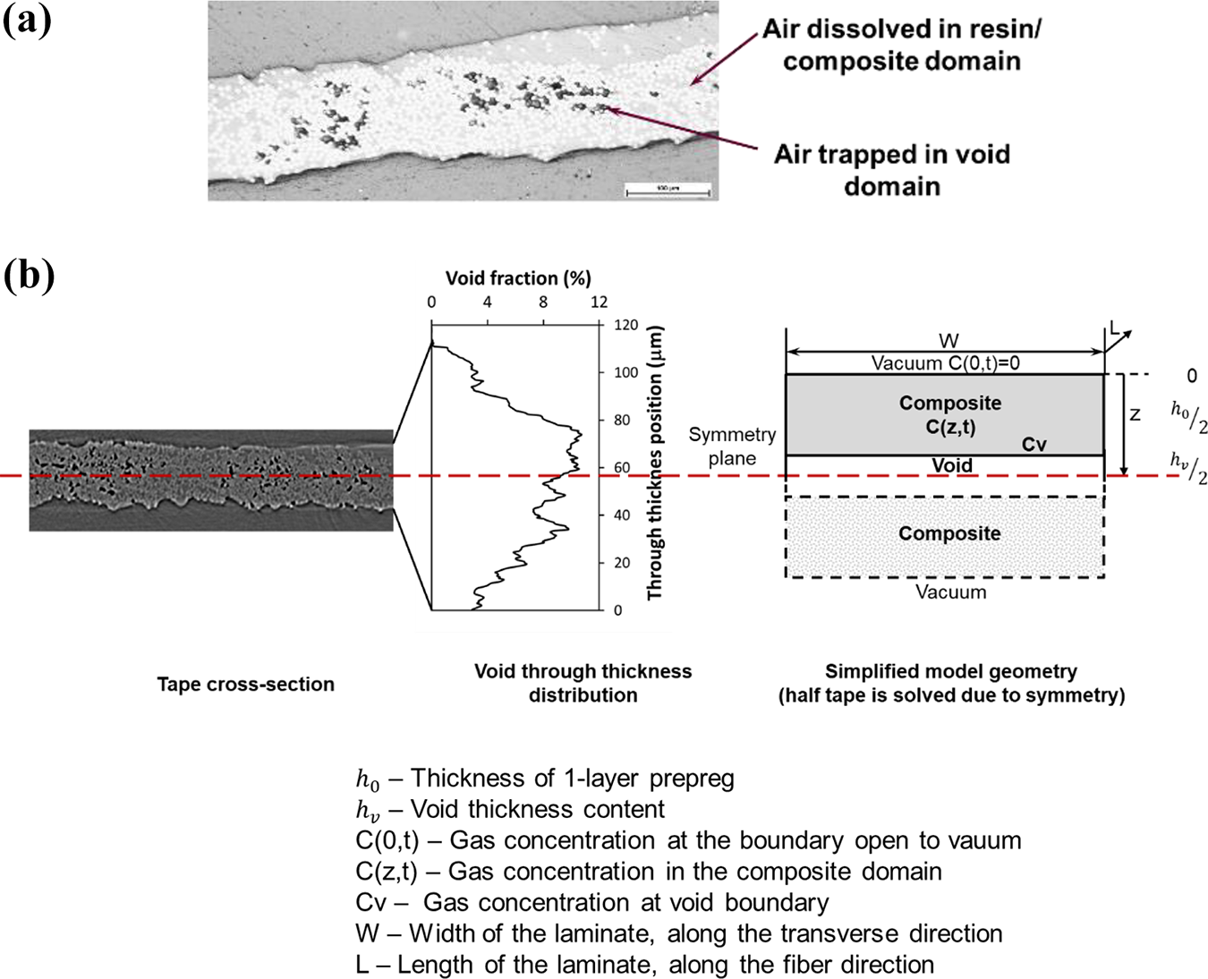
(a) Micrographs illustrating void location in APC2 prepreg and (b) simplified geometry for single layer diffusion model.
In this model, through-thickness diffusion of air molecules (79% N2 and 21% O2) is calculated in the composite domain. The void domain is a reservoir of air. Air flows in and out of the void space depending on the concentration gradient at the void boundary. Diffusion of air in the composite domain follows one-dimension Fick’s second law as

where cc is the concentration in composite region; the subscript g denotes the species of the molecules (N2 or O2). z is the position along the tape thickness with 0 at the tape surface.
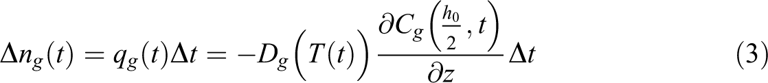
At the interface of the composite and void domains (void boundary), mass conservation applies, i.e. the amount of gas molecules goes into or out from void domain equal to that diffuse out from or into the composite domain. Therefore, at each time step
where qg is the diffusion flux. The pressure Pv and volume V of the void domain follows ideal gas law

where R is the gas constant. The void pressure Pv (Pa) is the sum of the partial pressure of N2 and O2

Since this is a 1D model through the thickness direction of the tape, the other two dimensions are assumed unit length and the void volume is represented by the void thickness. The concentration of gases at the void boundary follows Henry’s Law

where

where the initial partial pressure for N2 and O2 are


The initial amount of N2 and O2 in voids follows


where
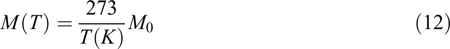
And M0 is the number of mol gases per unit gas volume under 1 atm pressure at 273 K, 44.6 mol/m3. The gas concentration at void boundary is given by
The partial pressure

In the void domain, two different boundary conditions are applied to Equation 5. When temperature is below the resin softening temperature (250–340°C for semicrystalline PEEK) the size of the voids hv is assumed to not change but the internal void pressure varies. Above this temperature, the pressure of the void domain equals to 1 atm at all time and the void size changes based on ideal gas law.
A finite difference method is adopted to solve the transient partial differential equation of diffusion in the thickness (i.e. “z”) direction given by Equation (1). Forward differencing method was applied. The continuity at the interface between the composite and void domains is maintained with mass conservation and Equation (3). In one timestep, the air concentration in the composite domain is solved with Equation (1), and the value at the void/composite interface is fed into the void space. The air pressure in the void domain is then obtained via Equation (6). Then, the number of air molecule flowing out from the void domain to the composite domain is obtained via Equation (4) and (5). With Equation (3), the number of molecules entering the composite domain at the interface for the next step is obtained. The calculation iterates with time until the amount of gasses in the void domain are negligible (e.g. less than 0.01% of the initial amount of air). A user interface model is developed integrating tape geometry and initial void content, processing cycle and vacuum level and the final amount of gas molecules in voids and void thickness. The effect of prepreg properties or processing conditions on the final void content (void size or amount of void air) can be evaluated.
Through-thickness diffusion in prepreg stacks
When the lateral edges of a prepreg stack are sealed, interlayer air is trapped in the laminate. In this case, the removal of air in both inter- and intra-layer voids relies on diffusion through the thickness of the full laminate. The model for single layer diffusion is extended to multilayer diffusion for laminates. Figure 3 illustrates the simplified geometry of the diffusion model of prepreg stacks with an example of a three-layer laminate. The intra-layer void domain is placed in the center region of each layer, while the interlayer void domain is in between two layers. For APC2 the interlayer void content is ∼20% of the prepreg thickness obtained from tape surface roughness characterization of the thermoplastic material. 1 The top and bottom surfaces of the laminate are exposed to vacuum; thus the diffusion is symmetric to the mid-plane of the laminate and solved through half of the laminate thickness in the multilayer diffusion model. There is no mass transportation across the symmetry center, thus the mass flux is 0. The equations for mass conservation, ideal gas law, and Henry’s law are applied to both intra- and interlayer void domain. The initial conditions and all boundary conditions in the model of single layer diffusion are applied to this multilayer diffusion model as well.
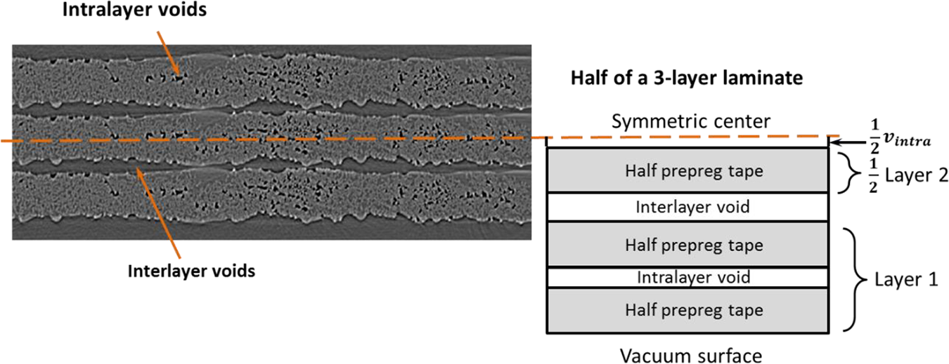
Simplified geometry for the model of diffusion through the thickness of prepreg stack with an example of a three-layer laminate.
Model for in-plane interlayer air flow
It is assumed that all air molecules (inter- and intra-layer) accumulate after diffusion at the interlayer and flow out to the vacuum edge. The interlayer region between two prepreg layers is simplified into a rectangular cavity as shown in Figure 4. The interlayer permeability does not change significantly until the process reaches the melt temperature and is constant throughout the evacuation process. Air transport out of the constant interlayer cavity (no change in volume until melt) changes the pressure in the cavity as a function of time and location (l). Following Darcy’s Law, the air flow rate is given by

where
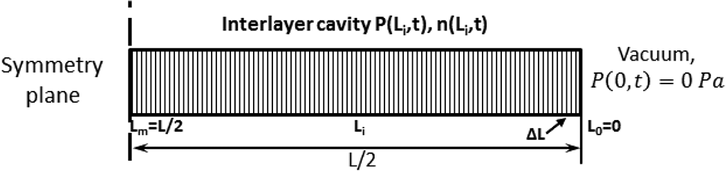
Schematic of air flow model in an interlayer cavity. L is the length of the interlayer cavity; the transient flow is solved with finite element method by dividing the entire cavity into sub-element with length of ΔL, and m is the total number of elements. i denotes the element index (i = 1,…, m). P(Li, t) and n(Li, t) are the pressure and amount of molecules of air in the ith element.
Equation 16 is satisfied for each element at each time step
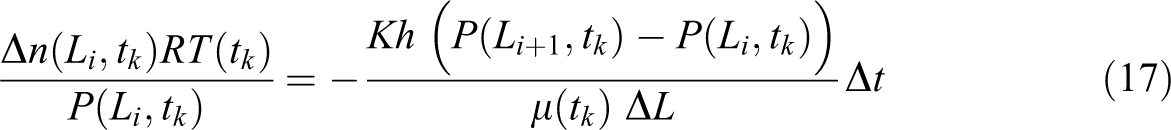
where k is the number of time steps, starting from 1, and T(tk) is the processing temperature as a function of time (in time steps during the calculation) when void air has diffused out from the single layer prepreg. Mass conservation gives the total amount of gas in each element after t

The new pressure in sub-cavity i at time t is
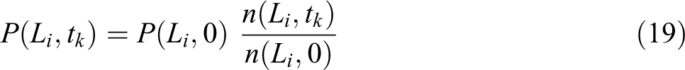
where,

The initial pressure in sub-cavity

where, vi is the interlayer void content representing the volume of the interlayer region. The dynamic viscosity of air (Pa.s) as a function of temperature is given by
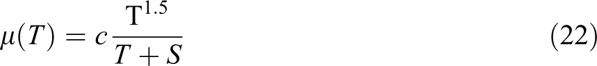
where c and s are constants, and c = 1.458 e−6 kg/(m s K1/2), S = 110.4 K for air. 14
The model will continuously run as a pressure/air concentration gradient will always exist in the domain without reaching a zero void content state. Thus, execution is stopped when all elements contain less than 1% original air amount (mol/mol).
Material and process parameters
The standard processing condition for APC2 is a 2.8°C/min heating cycle up to 380°C followed by cool-down. Experiments showed less than 10°C temperature gradient within a 72-layer laminate and thus for modeling purpose, full vacuum without a temperature gradient in the composite is assumed throughout the process. The solubility and diffusion coefficient of N2 in PEEK has been obtained by Ciora and Magill. 6 Since both N2 and O2 are simple gases dissolved in PEEK, and their dissolution in carbon fibers is ignored, the solubility and diffusion coefficient of N2 and O2 in composite tape as functions of temperature are estimated 5 and plotted in Figure 5. It is seen that the solubility of O2 decreases half an order of magnitude as temperature increases from room temperature to 380°C, while the reduction for N2 is about one order of magnitude. The diffusion coefficient for both N2 and O2 increases from 10−13 to 10−9 m2/s as temperature increases to 380°C.
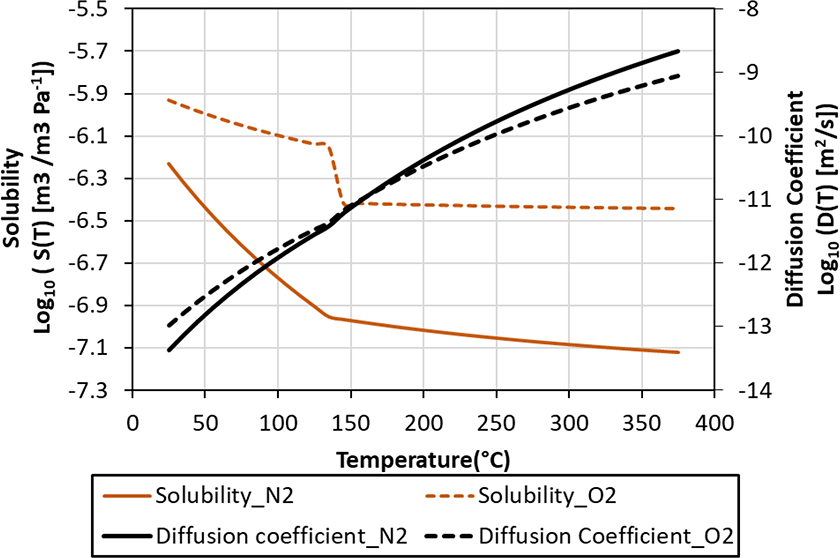
Solubility and diffusion coefficient of N2 and O2 in carbon fiber/PEEK composites with temperature used in the diffusion models. The step change for the solubility of O2 at glass transition is due to estimation.
The permeability thickness products
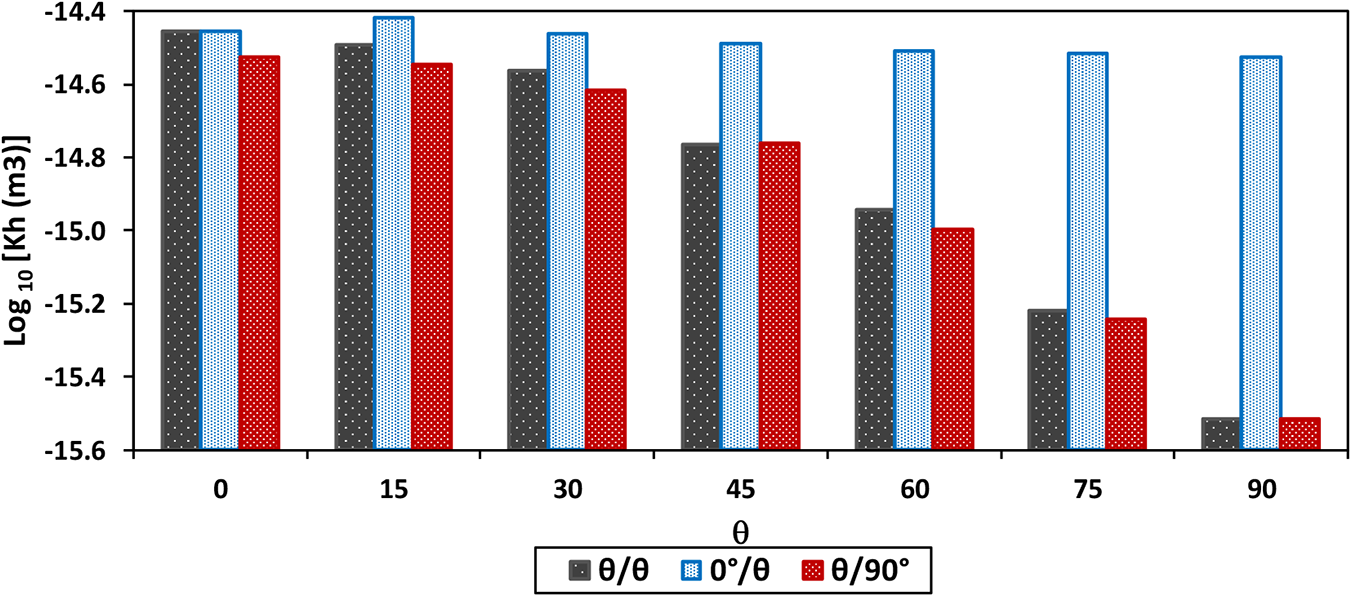
Permeability of interlayer region as a function of layup at room temperature, where θ is the angle between fiber direction to the flow direction, and the interlayer region is defined by the angles of the two contact layers to the flow direction.
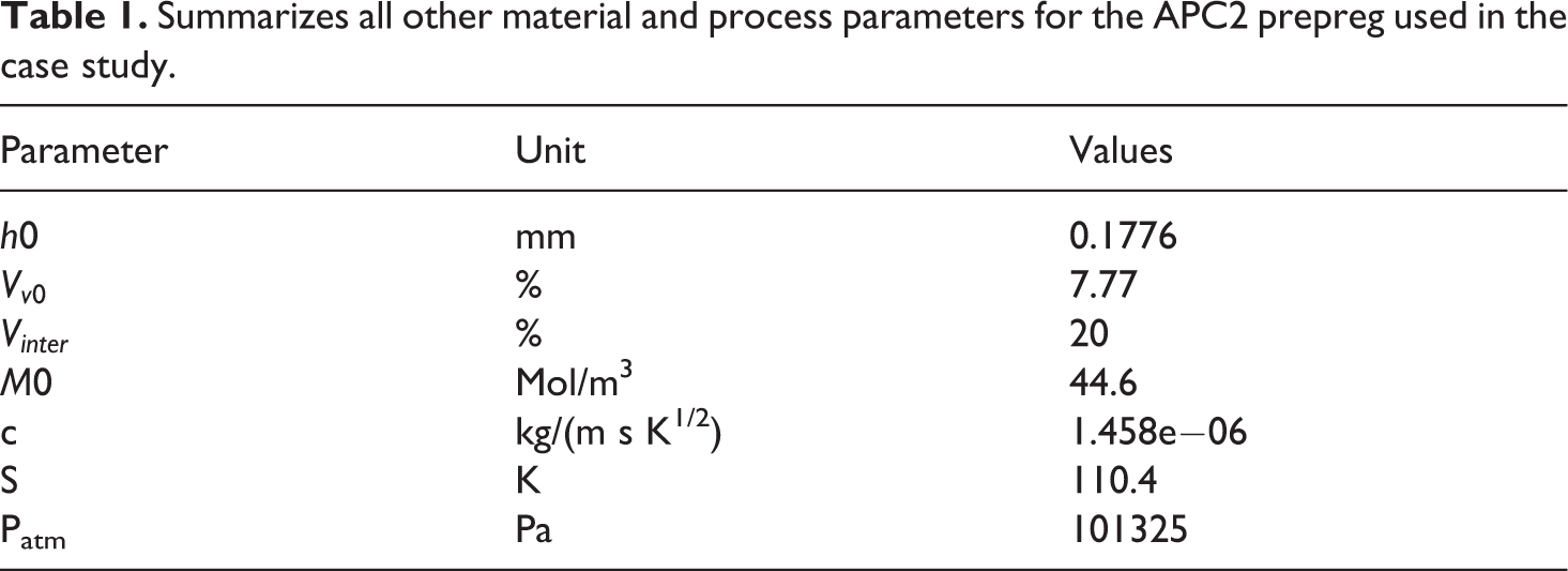
Summarizes all other material and process parameters for the APC2 prepreg used in the case study.
Model results and discussion
Air Removal in a Single Layer
The nitrogen concentration profile as a function of processing time in a single layer with vacuum applied on both boundaries is shown in Figure 7. The oxygen species behave similarly. Prior to the start of the vacuum and heating cycle, the polymer is saturated at the atmospheric and room temperature concentration (black solid line). At the early stage of heating, prepreg and air temperature increases, which increases void pressure and reduces solubility. Initially, solubility reduces faster than the temperature dependent pressure increase resulting in reduction of the gas concentration at the void boundary. The resulting concentration gradient creates a net flow of gas into the void cavity increasing pressure. At the vacuum boundary, concentration drops to zero and a gradient develops allowing gas flow out of the prepreg layer. The concentration drops slower in the prepreg half center, as gas needs to diffuse through the polymer to the adjacent boundary layer. At approximately 40 minutes, the concentration gradient at the void boundary inverts, and air can diffuse from the internal void region to the vacuum side. Process temperature continuous to rise and solubility drops. The transient process continues until all nitrogen is evacuated from the void volume at around 67 minutes.
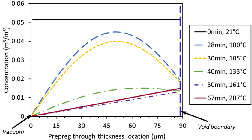
Concentration gradient of N2 in the composite domain in the model of single layer diffusion during the heating ramp.
Figure 8 shows the air concentration and pressure behavior in the void during single ply processing. Initially, void pressure and concentration is atmospheric. A net flow into the cavity until 60 min (negative concentration at the void boundary as seen in Figure 7) increases the amount of air in the void volume. Void pressure increases due to the additional air and temperature increase. The concentration gradient at the void boundary inverses at approximately 40 minutes allowing a net flow out of the void space. A maximum void pressure of 170 K Pa is reached at 40 minutes where the combination of processing temperature and air concentration peaks. Both pressure and air concentration reduce until all air is evacuated at ∼67 minutes where both drop to zero. Above the softening temperature of the prepreg, the void will completely collapse, and void volume will be zero in the single layer prepreg.
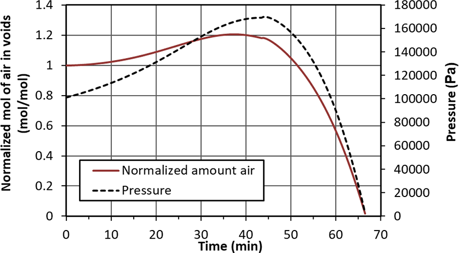
Normalized concentration and pressure development in the void region during processing of single layer prepreg.
There can be significant spatial variation in the initial void content of the tape material Figure 9 (a) shows the evacuation time of a single layer with different starting intra-layer void content. Lower initial void content leads to reduced processing times while larger void volume requires extended processing. Nevertheless, due to the increased diffusivity with temperature, doubling the void volume to 15% void volume increases processing time only by 6 minutes to 71 minutes compared to 65 minutes in the 7.77% baseline material. Thus, even a larger void volume can be evacuated in the single ply setup. Another consideration is the effect of ply thickness on processing. Thin ply variants are currently evaluated to improve damage tolerance while thicker plies can be considered to reduce placements time. Figure 9 (b) shows the effect layer thickness on evacuation time. The processing time required for void air evacuation based on diffusion mechanism increases with ply thickness. It is seen that the processing time for a ply thickness of 50 µm is only 43 minutes. Even for a layer thickness of 300 μm, the void air can be evacuated within 80 minutes, corresponding to processing temperature of ∼250°C, below the resin melting temperature.
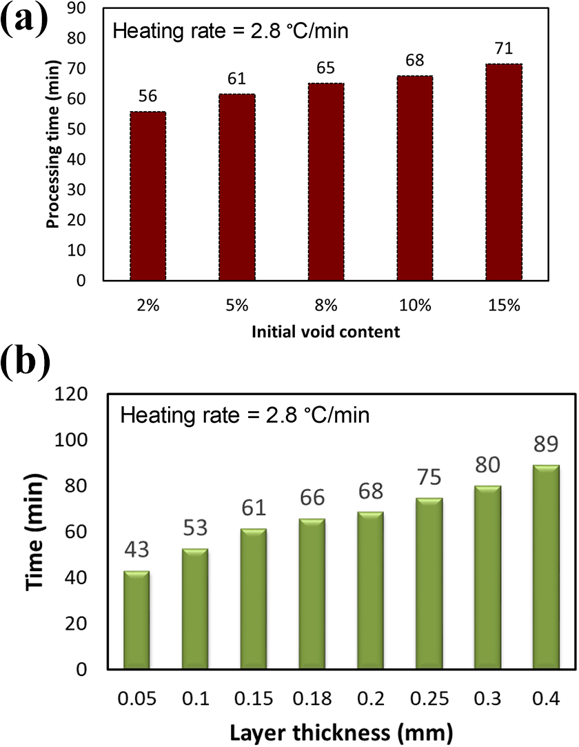
Processing time for void removal through single layer diffusion with (a) different initial tape void content and (b) tape thickness.
Air removal in the edged-sealed multilayer laminate
For a laminate with lateral edges sealed in the OVB processing, void air removal can only rely on diffusion through the complete thickness of the prepreg stacks. The concentration profiles of N2 in the composite domain of a five-layer stack during the temperature ramp are shown in Figure 10 (2.5 symmetric layers results are modeled to illustrate the behavior of any multi-ply setup). At the early stage of heating, the dissolved air in the composite domain diffuses into each adjacent void domain, similar to the single ply setup. In effect, concentration gradients are almost identical for all half layers where both boundaries have voids with finite amount of air remaining. The only difference is the difference in void volume and change in gas pressure due the net flow in or out of the void domain. Eventually a concentration gradient develops in the top layer between the vacuum and first void space allowing a net reduction of air until all gas is evacuated. A new concentration gradient develops between the vacuum surface and second void and gas is extracted. This will repeat until the process evacuates the air from all void spaces, temperature reaches the softening temperature where void collapses or when the process cycle is finished.
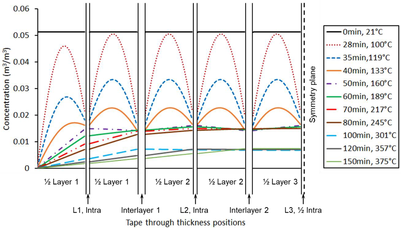
Concentration profile of N2 in a five-layer laminates.
Figure 11 shows the normalized amount of air increasing above 1 during the initial heating cycle for all void spaces. The surface intra-layer void reduces, similar to the single ply but slower as the diffusion of the void space occurs through one surface layer only. The surface intra-layer void space is fully evacuated at around 95 minutes at which point the gradient to the next void space develops and increases the flow out of the next void volume. This repeats until all voids in the first two layers are evacuated at around 160 minutes into the processing cycle. In this experiment cycle, the temperature is immediately decreased after reaching 380°C. The time at high temperature to evacuate void air in the third layer is not long enough. Therefore, the void in the third layer is not fully removed before resin solidified. The void air diffusion behavior continues for thicker prepreg stacks where additional voids continue to be evacuated as long as vacuum and temperature is applied to the material. It is noted that the first void collapse coincides with the process temperature reaching the softening point of the polymer. This changes the void pressure to 1 atmosphere which affects the boundary concentration, gradient development and air concentration in the void as well.
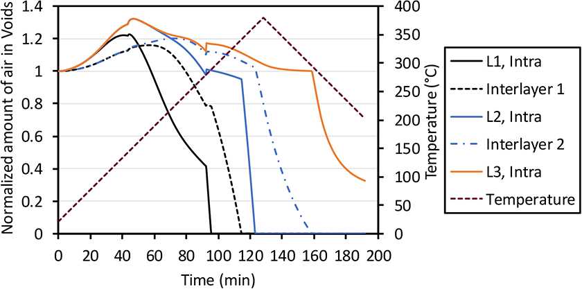
Normalized amount of air in each intra- and interlayer void domain of a five-layer laminate.
The evolution of the thickness of the void domains during heating is presented in Figure 12. Our modeling assumptions place all void space centered (intra voids) or at the interface (inter voids) of each layer. Due to the higher void content in the interlayer region compared to voids inside the tape, void thickness of interlayer voids is higher than that of the intra-layer voids. The thicknesses of all voids do not change before the resin softening point of 280°C. Above 280°C, the void thickness changes instantly at a ratio of the internal void pressure prior to reaching the softening point and 1 atmosphere applied during the vacuum step. The void thickness reduces with the reduction of the amount of air inside the voids, and collapses starting from the surface layers to the inside layers.
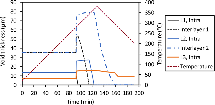
Thickness of each intra- and interlayer void domain of a five-layer laminate during the heating ramp of consolidation experiment for thick laminates. Note that the void thickness of L1 at temperature below 280°C is the same as L2. The black solid line is hidden underneath the blue solid line in this region.
The diffusion times required to eliminate all voids in laminates having 1 to 72 layers (nominal total laminate thickness of 12.8 mm) are calculated with the multilayer diffusion model for various intra-layer void contents and is shown in Figure 13. The heating ramp to 380°C allows void reduction in up to five-layer thick stacks for the average measured void content level of 7.7%. Extending the high temperature dwell is needed for thicker parts and processing times increase significantly with 177 hours needed for a void free 72-layer stack which potentially can degrade the material. The processing times increase as tape void levels increase, 216.5 hrs is needed for tape void content of 15%, 39 hrs more than the tape with 7.77% void content. This will potentially degrade the material. However, if the tape void content can be reduced to 1%, the diffusion time for a 72-layer thick laminate can be reduced by 38 hrs. If the tape is smoother with smaller interlayer void region, the diffusion time through the thickness of the laminates can be further lowered.
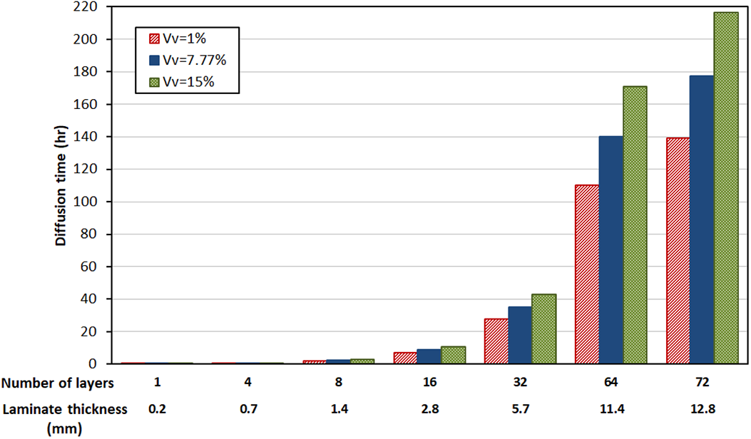
Diffusion time to achieve a void free laminate for 1 to 72-layer laminates with different initial void content within the prepreg tapes.
Air removal in laminates with perimeter open to vacuum
Air removal with perimeter open to vacuum behaves significantly different in thick or smaller parts where interlayer voids are evacuated quickly through the perimeter vent. This creates a pressure drop in the interlayer region, which subsequently leads to gas transport from internal voids into the interlayer, with continuing flow to the perimeter until all gas is evacuated. A coupled model is needed to fully capture this behavior, which is beyond the scope of this paper. In order to estimate total void evacuation times, we assume that perimeter flow starts after 65 minutes at processing temperature of ∼200°C for Vintralayer = 7.77% where all internal tape voids have been evacuated into the interlayer region. A dwell cycle at 200°C maintains layer permeability without polymer flow allowing air evacuation via the interlayer air flow mechanism without degrading the material. After full air removal the part is consolidated with the standard consolidation cycle.
Interlayer air evacuation time highly depends on the part in-plane dimension (flow length) and the interlayer permeability. The air evacuation time for part in-plane dimension up to 100 m are estimated over the range of experimental
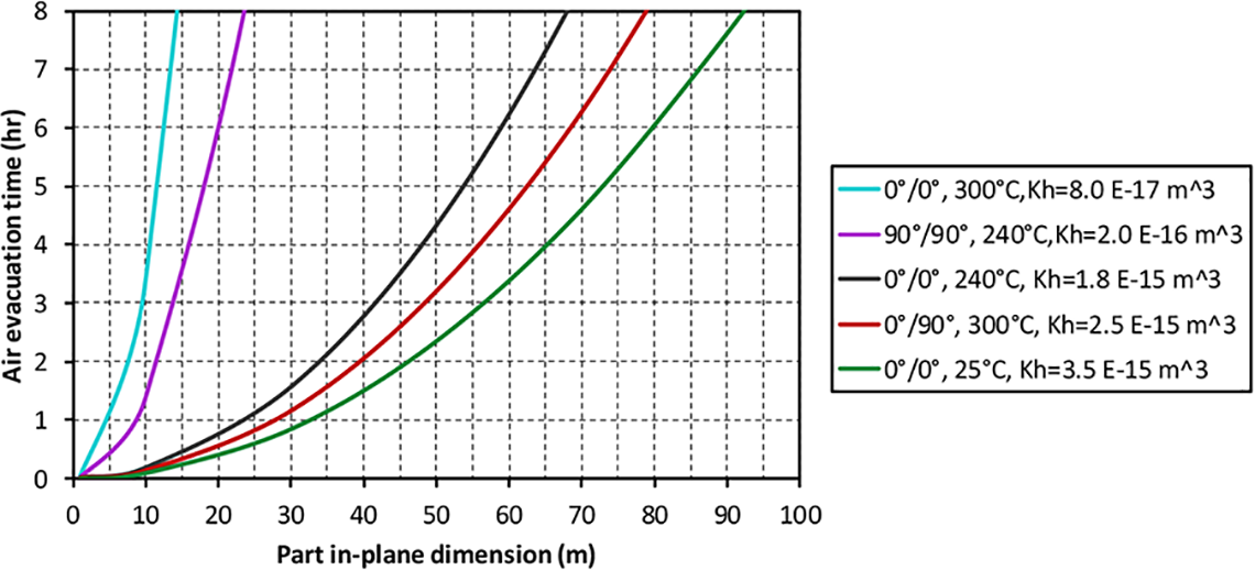
Air evacuation/dwell times for different part in-plane sizes under permeability thickness products of 8E−17 m3 to 3.5E−15m3 (Vv = 7.77% and Vinterlayer = 20%).
The effect of higher initial intra-layer void content is considered in Figure 15. With both low and high interlayer permeability, higher tape void content requires longer diffusion and air evacuation times as additional gas has to be evacuated to and through the interlayer. Therefore, the dwell cycle required for volatile evacuation depends on the initial void content. Additionally, if the interlayer permeability is higher, shorter time is required to evacuate the void air, as the red line is lower than the blue line in Figure 15.
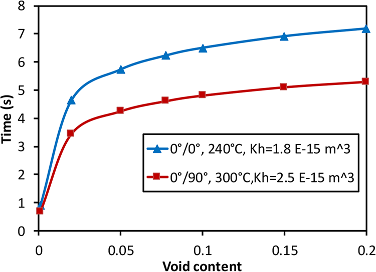
Air evacuation/dwell times with different initial void content in a part size of 50 m starting from 0.1% to 20%.
The data demonstrates the ability of interlayer flow in OVB processing to improve porosity reduction in thick-section composite parts without requiring long processing times even in large parts. The approach requires good transition of the prepreg edge into the venting system. Local pressure intensification needs to be avoided to ensure high permeability of the interface at any location in the layup.
Conclusions
Void air removal in high-performance thermoplastic composites in OVB processing is modeled based on two mechanisms, through-thickness diffusion and airflow through the interlayer region if perimeter vacuum venting is applied. The important material properties of AS4/APC2 carbon PEEK prepreg have been generated or collected from literature and include diffusivity/solubility as a function of processing temperature and permeability of the interlayer interface for various stacking sequences. Recommended manufacturer processing cycles are applied to demonstrate the modeling capabilities.
The modeling results show the limitation of through-thickness diffusion to manufacture thick-section components using OVB processing. The addition of perimeter venting does allow high quality part fabrication independent of thicknesses and with large in-plane geometries. The key is to rely on the in-plane permeability of each interface to transport both intra- and interlayer void volume through the interface into the perimeter vent. The model predicts part geometries of 50 m and longer can be produced using the proposed process.
The effect of initial void content and prepreg thickness on single layer diffusion time has been evaluated and can affect processing time. Multilayer processing with diffusion only is very sensitive to as received prepreg material variation. The material quality also affects processing time for in-plane gas transport. Nevertheless, adding an intermediate dwell cycle at 200°C to the process allows diffusion and in-plane air flow out of the part without affecting the interface permeability and creates a very robust process for a wide variation of material properties.