
Abstract
Graphene–polymer nanocomposites have shown promising potential as high dielectric constant and electrostatic energy storage materials. However, such nanocomposites often faced challenges of high energy dissipation and low voltage endurance due to direct contact of graphene nanosheets and localized electric field concentration. Various efforts have been made to address these shortcomings such as the insulative coating of graphene nanosheets in a polymer matrix. In this study, we simulated (using COMSOL Multiphysics) the effects of such insulative coatings on localized voltage concentration around graphene nanosheet in a polymer matrix. The simulation was done by consideration of various insulative materials with different dielectric constant and coating thickness on graphene nanosheets. It was noted that insulative coating can reduce localized voltage concentration around a graphene nanosheet in a polymer matrix, thereby improve the breakdown strength. Further increase in the coating thickness with low dielectric constant coating materials can further enhance breakdown strength. However, high coating thickness resulted in lowering the microcapacitance of the microcapacitor in the polymer matrix. Therefore, for the optimal energy density of such nanocomposites, a compromise dielectric constant of a coating material and coating thickness on graphene nanosheet must be reached. This study showcased the influence of insulative coatings on graphene nanosheets. It will be a guide for further studies on the selection of coating materials for graphene nanosheets for high breakdown strength nanocomposites.
Introduction
It has been noted that single dielectric materials such as pure polymer or ceramic cannot give dielectric constant required for next-generation electronic applications such as capacitor for high energy storage and materials for electromagnetic shielding. Therefore, the incorporation of high dielectric constant fillers in a polymer matrix to enhance its dielectric constant and energy storage capacity has been in practice.1,2 Recently, conductive carbon-based fillers such as graphene have shown significant improved dielectric constant when incorporated in a polymer matrix.3–5 The enhanced dielectric properties often associated with such nanocomposites are believed to be due to excellent properties of graphene nanosheets such as high electrical and thermal conductivity and their ability to formed microcapacitors in a polymer matrix.6,7 Graphene is a 2D carbon-based material bonded in the sp2 honeycomb structure. The high aspect ratio, large surface area and plate-like structure of graphene make it easy to form microcapacitors when incorporated in a polymer matrix. When adjacent graphene nanosheets are separated by an insulative polymer matrix, it formed a structure of graphene–polymer–graphene, which is termed as microcapacitor. This often results in a high dielectric constant output of such nanocomposites.
On the other hand, graphene–polymer nanocomposites are often associated with high dielectric loss and low breakdown strength.8,9 Although understanding the microstructural interpretation of these shortcomings is difficult, research has attributed them to direct contact of graphene nanosheets, high mobility of charge carriers and localized electric field around graphene nanosheets in the polymer matrix. 6 These challenges have limited practical application of graphene–polymer nanocomposites as high dielectric constant materials for energy storage applications. This is because higher energy loss is not desired in energy storage and high voltage endurance is required for high energy storage capacity. Various efforts have been made to address these limitations by the insulation of graphene nanosheets in polymer matrix.10–12 For instance, graphene nanosheets have been coated or insulated in a polymer matrix using inorganic materials such as TiO2, 13 SiO2 8 and BaTiO3 9 on the effort to mitigate the challenges facing such nanocomposites. While other studies have shown insulation of graphene with organic substances.7,14 Significant reduction in energy dissipation and enhanced breakdown strength have been achieved using various insulative materials and coating techniques. However, there is a discrepancy in the proximity of results obtained by various studies, which is believed to be due to variation in dielectric constant and coating thickness of the insulative materials used.
Therefore, it becomes important to understand the contribution of the dielectric constant and coating thickness of the major materials used for this purpose on voltage distribution (which results in localized voltage concentration) and energy dissipation around graphene nanosheets in a polymer matrix. Hence, this formed the focus of this present study. This investigation was carried out by simulation of electrostatic behaviour of insulated graphene nanosheets in polymer matrices using COMSOL Multiphysics software. This software can simulate the electrostatic behaviour of a component among others, which is based on the finite element method.15,16 This software has been used by various studies in the simulation of electrostatic behaviours. For instance, Das et al. 17 investigated voltage and capacitance of electrowetting on dielectric using COMSOL Multiphysics. While modelling of electrical capacitance tomography sensor has also been reported using COMSOL Multiphysics. 18 Similarly to this study, Wang et al. 19 examined the electric field distribution of dielectric composites containing core–shell filler particles using phase-field modelling. The study was based on a high dielectric constant spherical core and low dielectric constant core–shell and matrix.
Therefore, in this study, we report the microelectrostatic behaviour of insulated high conductive graphene in a polymer matrix using COMSOL Multiphysics. For the first time, this study simulated insulated graphene nanosheets in a polymer matrix to understand the distribution and concentration of electric field around graphene nanosheets, which often result in low breakdown strength and high energy loss. Major materials used in insulating graphene nanosheets such as BaTiO3, TiO2 and SiO2 were considered at various coating thicknesses. It was noted that the low breakdown strength of such graphene–polymer nanocomposites can be significantly improved by the insulation of graphene nanosheets in a polymer matrix with high coating thickness and low dielectric constant insulating materials. On the other hand, high coating thickness on graphene nanosheets resulted in low microcapacitance density. Therefore, this study is a guide on proper tailoring and designing of optimal dielectric properties of graphene–polymer dielectric nanocomposites. This study will further guide in the selection of polymer matrix, coating material and coating thickness for the reduction of localized voltage concentration in the polymer matrix and enhance energy storage capacity.
Background
Graphene nanosheets tend to form microcapacitors in a polymer matrix. As shown in Figure 1(a), the microcapacitors are formed within a matrix when adjacent graphene nanosheets are separated by thin polymer layers, which results in to increase in dielectric constant or energy storage capacity of such nanocomposites. The graphene nanosheets are interconnected in the matrix, which often results in high electrical conductivity and energy dissipation. When the external electric field is applied, there is often a heterogeneous accumulation of charges at the graphene–polymer interfaces in accordance with Maxwell Wagner Sillar’s theory as shown in Figure 1(a). The graphene–polymer interfaces often serve as dielectric breakdown sites due to higher accumulation of charges and electrical conductivity of graphene nanosheets compared to the bulk polymer matrix. To address these challenges, efforts have been made by coating graphene nanosheets with insulative materials in the polymer matrix. This technique often cloths both sides of the graphene nanosheets with the insulative materials as shown in Figure 1(b), to prevent them from direct contact, the formation of conductive pathways, high electrons mobility of electrons, high energy loss and low breakdown strength.
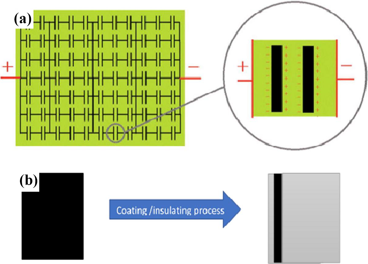
(a) Schematic representation of microcapacitors formed within polymer matrix 20 (b) schematic representation of graphene nanosheet (core) and coated graphene nanosheet (clothed core).
Various insulative materials have been used to achieve the clothing of graphene nanosheets in the matrix. These materials include but not limited to BaTiO3, TiO2 and SiO2, which are also considered in this study. It is worth noting that these materials have distinct properties, such as electrical resistivity, dielectric constant, thermal conductivity, and so on. These properties affect the behaviours of insulated graphene in a polymer matrix. Also, the coating thickness of the insulative materials affects the performance of insulated graphene nanosheets in the matrix. Therefore, the simulation in this study took into account these factors affecting the performance of insulated graphene nanosheets in terms of localized voltage concentration and microcapacitance. The coating thickness was varied from 5 nm to 10 nm for BaTiO3, TiO2 and SiO2 with a fixed dielectric constant of 700, 60 and 3, respectively. Dielectric constants of 10 and 2 were used for the poly(vinylidene fluoride) (PVDF) and polypropylene (PP) matrix, respectively. The choice of the coating thickness variation was based on coating ranges previously reported in experimental studies carried out by Han et al. 8 and Liu et al. 21 On the other hand, graphene nanosheets (core) were considered as 1 nm thickness and few micrometers by width.
Detail understanding of the microstructure of graphene–polymer nanocomposites is complicated due to a high agglomeration of graphene nanosheets in a polymer matrix. For simplicity, this study assumed a well-dispersed graphene in a polymer matrix and considered two insulated graphene nanosheets separated by the thin polymer matrix. Therefore, the effective dielectric constant of the insulative material on the surfaces of the two graphene nanosheets and the thin matrix can be obtained from microcapacitance of the microcapacitor formed in the matrix as shown in equation (1).


where Ceff, Cm and Cc are the capacitance of the microcapacitor, matrix and coating, respectively. deff and dm are effective distance and matrix between the two graphene nanosheets, while dc is the coating thickness on the graphene nanosheets. εeff, εm and εc are the dielectric constant of the microcapacitor, matrix and coating, respectively. A is the average area of the microcapacitor.
Electrostatic model equations and boundary conditions
Electrostatic equations are used in the determination of energy stored (ES) in a capacitor system. The electrostatic model is one of the physics found in COMSOL Multiphysics for electrostatic simulation. An electrostatic capacitor consists of two parallel conducting plates separated by a dielectric material (insulator). ES in such a system is estimated by the effective electric charges (Q) on a conductive plate and the voltage (V) across the dielectric material as shown in equations (4) and (5).


where C is the capacitance, εo is the permittivity of free space, εr is the dielectric constant, A is the area of the capacitor plate and d is the thickness of the dielectric material.
Electrostatic model in COMSOL Multiphysics has the capability to estimate electric field distribution around such a capacitor system using finite element analysis. 17 The electric field distribution and accumulation of charges around dielectric material determine its breakdown strength. In this present study, such a model was applied on a microcapacitor within a polymer matrix to predict its microelectrostatic behaviour. Such an electrostatic model satisfies and solves Poisson’s equation as shown in equation (6). 22 The electric field (E) and displacement (D) can be expressed as shown in equations (7) and (8).


where ρ is the space charge density and V is the electric potential.
Appropriate boundary conditions were applied: ground boundary condition was applied on the lower graphene nanosheets and terminal boundary condition was applied on the upper graphene nanosheets as applied voltage of 5 V. Other boundaries considered in the simulation were set to zero charge condition as shown in equation (9). Distributed capacitance of the system is expressed in equation (10). 18 The matrix was kept fixed as insulator and domain for the microcapacitor simulation. The simulation domain was appropriate to take care of the fringing field from the microcapacitor. In addition to the setting of boundary conditions, the appropriate meshing of the components was done. The components were meshed in 2D using a free triangular meshing type as found in the COMSOL Multiphysics software. To ensure accuracy, different zones were meshed separately with different meshing parameters. 18 Uniform distribution of mesh-network in each zone was achieved, which facilitated the proximity of the results obtained in the simulation.


Results and discussion
Voltage distribution around insulated graphene nanosheets
Currently, various studies have introduced carbon-based percolative fillers such as graphene nanosheets in a polymer matrix to enhance the energy density of such material. Various studies have reported a decrease in the breakdown strength of such polymer–graphene nanocomposites.3,9 The low breakdown strength of such nanocomposites is due to direct contact of graphene nanosheets, accumulation of charges around the graphene nanosheets, local electric field or voltage distribution around graphene nanosheets in a polymer matrix. A large electrical mismatch between graphene and polymer matrix also contributes to the reduction in breakdown strength of such nanocomposites. 23 These have led to insulation coatings on graphene nanosheets with various insulative materials to improve breakdown strength or energy dissipation of polymer–graphene nanocomposites. Therefore, this study simulated the effects of various insulative coating materials on localized voltage distribution around graphene nanosheets in polymeric materials. First, we considered graphene nanosheets insulated with SiO2, TiO2 and BaTiO3 in PVDF matrix as shown in Figure 2. It was noted that coatings on graphene nanosheet can protect it from severe localized voltage concentration. Thereby, improving the breakdown strength of such nanocomposites. However, the dielectric constant and thickness of the insulative coating on the graphene nanosheets have a great role to play in the reduction of the localized voltage concentration. The dielectric constant of the matrix is also an essential factor to be considered in the selection of insulative coating materials. In this study, the dielectric constant of PVDF was set at 10, which is less than that of TiO2, BaTiO3 and greater than that of SiO2.
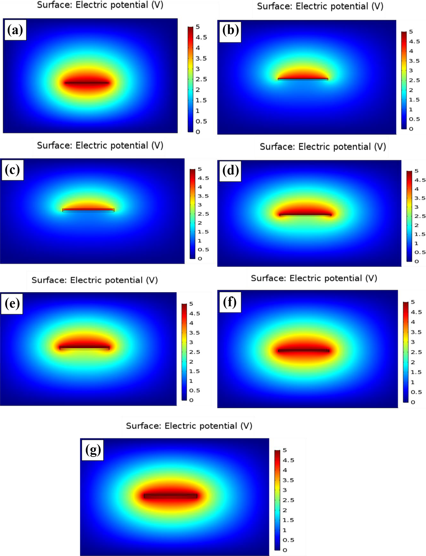
Voltage distribution around (a) bared graphene sheet; coated (b) 5 nm SiO2 (c) 10 nm SiO2 (d) 5 nm TiO2 (e) 10 nm TiO2 (f) 5 nm BaTiO3 and (g) 10 nm BaTiO3 on graphene nanosheets within PVDF matrix.
Figure 2(a) shows severe voltage distribution around bared graphene nanosheet in the PVDF matrix. The localized voltage is severely concentrated at the two poles of the graphene nanosheet, then distribute outward into the matrix. This is because, on the application of external electric field, heterogeneous accumulation of charges at the two poles of graphene nanosheet occurred, which often result in the accumulation of electric field and a decrease in breakdown strength. 24 After coating the graphene nanosheet with 5 nm SiO2, the localized voltage concentration reduced (Figure 2(b)). As the SiO2 coating thickness increased to 10 nm, the localized voltage concentration became lesser severe (Figure 2(c)) compared to bared and 5 nm SiO2-coated graphene nanosheets. This shows the effect of such low dielectric constant coating material in the reduction of localized voltage concentration and the improvement of breakdown strength. It was also noted that at a coating thickness of 10 nm SiO2, the localized voltage concentration extended only slightly into the matrix with a significant reduction at the polymer–graphene interface (Figure 2(c)) compared to 5 nm SiO2 coating. This indicates that the breakdown strength of such nanocomposites can be reduced since localized voltage concentration at the polymer–graphene interface is decreased. On the other hand, when simulated under TiO2-coated graphene nanosheet condition, the localized voltage concentration was more severe compared to SiO2 coating, but lesser than bared graphene nanosheets in PVDF matrix as shown in Figure 2(d) and (e). As was also noted with SiO2 coating, 10 nm TiO2 coating showed lesser localized voltage concentration compared to 5 nm TiO2 coating on the graphene nanosheet. A similar observation was also made when simulated under the BaTiO3 coating condition. However, due to the high dielectric constant of BaTiO3 (set as 700), graphene nanosheet coated with BaTiO3 in the PVDF matrix showed an almost similar effect of localized voltage concentration (Figure 2(f) and (g)) when compared to bared graphene nanosheet. This can be attributed to the direct relationship between dielectric constant and electrical conductivity, which often resulted in a high accumulation of charges at the interface of graphene and the coating material. As demonstrated in Figure 2(g), high BaTiO3 coating thickness resulted in decreased localized voltage at the polymer–BaTiO3 coating interface. However, it can be concluded that high dielectric coating materials (BaTiO3) might not significantly improve the breakdown strength of the nanocomposites compared to low dielectric constant coating materials (SiO2). Even with a low dielectric constant coating material, high coating thickness is required to significantly reduce localized voltage concentration and improve the breakdown strength of such nanocomposites. Therefore, a compromise must be reached in the selection of coating materials for graphene nanosheets and coating thickness for optimal reduction of localized voltage concentration and improves breakdown strength.
As stated earlier, the dielectric constant of the polymer matrix also influenced the localized voltage distribution around graphene nanosheets. This was demonstrated by using another polymer matrix (PP) as shown in Figure 3. The dielectric constant value of PP was set as 2, which is lesser than that of all the coating materials considered in this study. The simulation of SiO2-coated graphene nanosheet in the PP matrix showed severe localized voltage concentration (Figure 3(b) and (c)) compared to the same class of coated graphene nanosheet in the PVDF matrix (Figure 2(b) and (c)). This is due to the low dielectric constant of the PP matrix, which resulted in a high concentration of localized voltage around the slightly higher dielectric constant coated surface. With the high dielectric constant of the TiO2-coated interface in the PP matrix, severe localized voltage concentration was observed compared when simulated in the PVDF matrix. A similar observation was also noted with BaTiO3-coated graphene nanosheet in the PP matrix. The severe localized voltage concentration around BaTiO3 was due to the large dielectric constant between the matrix and BaTiO3 interface. This also resulted in electric field distortion and enhancement due to the heterogeneous accumulation of localized electric field. 25 Also, a large difference in surface energy between the matrix and BaTiO3 contributed to the observation. This is a clear indication that the dielectric constant of a polymer matrix is essential to be considered before the selection of coating material for graphene nanosheets in the polymer. In general, coated graphene nanosheets in the PP matrix shown in Figure 3 revealed a reduction in localized voltage concentration as was also noted with coated graphene nanosheets in the PVDF matrix in Figure 2. Therefore, for an optimal reduction in localized voltage concentration, high breakdown strength and high energy storage density nanocomposites, a compromise must be attained between the dielectric constant of the matrix, coating material, and coating thickness.
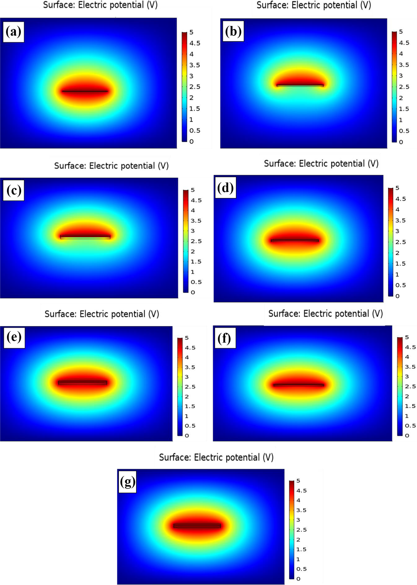
Voltage distribution around (a) bared graphene sheet; coated (b) 5 nm SiO2 (c) 10 nm SiO2 (d) 5 nm TiO2 (e) 10 nm TiO2 (f) 5 nm BaTiO3 and (g) 10 nm BaTiO3 on graphene nanosheets within PP matrix.
Voltage distribution across insulated graphene microcapacitor
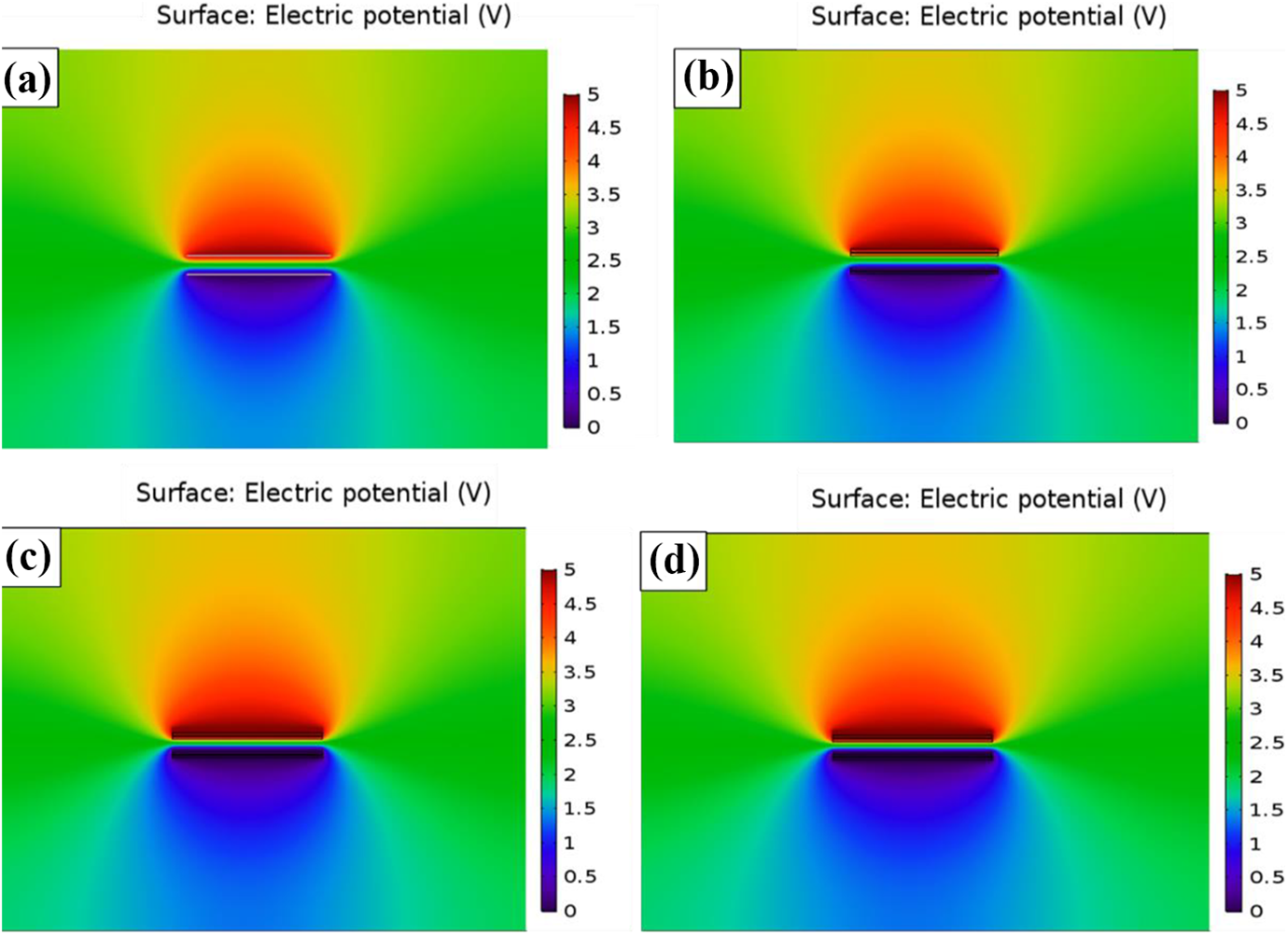
When adjacent graphene nanosheets in the polymer matrix are separated by polymer layers, they form a microcapacitor in the matrix. For a polymer–graphene nanocomposite, many microcapacitors are formed in the matrix depending on the volume fraction and dispersion of graphene in the matrix. It should be noted that polymer layers separating individual graphene nanosheets and the distance between the individual graphene nanosheet in a polymer matrix cannot be equal. When these microcapacitors are formed in the polymer matrix, localized voltage is concentrated around them, while some voltage tends to pass from one graphene nanosheet to another through polymer layers between individual graphene nanosheets. For this study, we assumed a certain distance between two graphene nanosheets separated by a polymer matrix. Appropriate boundary conditions were applied considering the polymer matrix as the domain for the microelectrostatic simulation. Figure 4 depicts the simulation of microcapacitors in the PVDF matrix. The localized voltage on the upper terminal bared graphene nanosheet was more severe and a higher percentage of voltage intends to pass through the polymer layer to the lower terminal bared graphene nanosheet (Figure 4(a)) compared to graphene nanosheets coated with SiO2 (Figure 4(b)). On the other hand, microcapacitors formulated in the PVDF matrix by high dielectric constant TiO2- and BaTiO3-coated graphene nanosheets, showed more concentrated localized voltage on the upper terminal graphene nanosheets and a high voltage across the polymer layer between graphene nanosheets. This confirmed the results obtained in Figure 2. A similar observation was also made when simulated similarly coated graphene nanosheet in the PP matrix as shown in Figure 5. In general, high dielectric constant coating materials are not always favourable for reduced localized voltage concentration and high breakdown strength, but it is essential for high dielectric constant or capacitance as shown in the next section. Hence, appropriate consideration must be made in the selection of materials for coating graphene nanosheets in a polymer matrix for various applications.
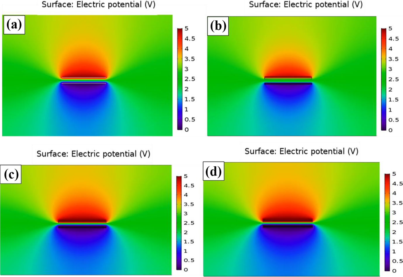
Voltage distribution in microcapacitor system (a) bared graphene sheet; graphene nanosheet coated with (b) SiO2 (c) TiO2 and (d) BaTiO3 within PVDF matrix.
Voltage distribution in microcapacitor system (a) bared graphene sheet; graphene nanosheet coated with (b) SiO2 (c) TiO2 and (d) BaTiO3 within PP matrix.
Surface charge and microcapacitance density of the microcapacitors
Figure 6 shows surface charge and microcapacitance density of the formulated microcapacitors illustrated in Figures 4 and 5, respectively. On the application of electric field on the microcapacitors, there is the heterogeneous accumulation of charges at the fillers’ interfaces according to Maxwell Wagner Sillar’s theory. The accumulated charges per unit area were computed as the surface charge density of a microcapacitor. On the other hand, microcapacitance density of a microcapacitor was computed as the ratio of surface charge density per unit applied voltage as shown in equation (4). From Figure 6, it can be seen that the dielectric constant of the coating materials and the coating thickness have a great effect on the surface charge and microcapacitance density of the micro capacitors formulated in both PVDF and PP matrices. Unlike the localized voltage concentration that is minimized by low dielectric constant coating shell and high coating thickness, surface charge and microcapacitance density of the microcapacitors are improved with high dielectric constant coating shell and low coating thickness. This indicates that the factors or parameters that improve the breakdown strength of insulated graphene–polymer nanocomposites, might negatively affect the energy storage capacity of such nanocomposites. Since high breakdown strength and low energy dissipation of graphene–polymer nanocomposites are required, high capacitance or dielectric constant is all needed for a high energy density of such nanocomposite. Hence, in the selection of coating materials for graphene nanosheets in a polymer matrix, proper consideration must be ascertained between the dielectric constant of the coating materials and coating thickness on graphene nanosheets. Also, surface charge and microcapacitance density of the microcapacitors formulated in the PVDF matrix are higher (Figure 6(a) and (b)) due to its larger dielectric constant compared to those formulated in the PP matrix (Figure 6(c) and (d)). Notably, surface charge and microcapacitance density of the microcapacitors in the PP matrix showed a more significant dependency on coating thickness than those simulated in the PVDF matrix. Again, surface charge and microcapacitance density of the microcapacitors formulated by BaTiO3-coated graphene nanosheets showed negligible dependency on the coating thickness in both matrices. This can be attributed to the high dielectric constant and stability of BaTiO3 coating shell.
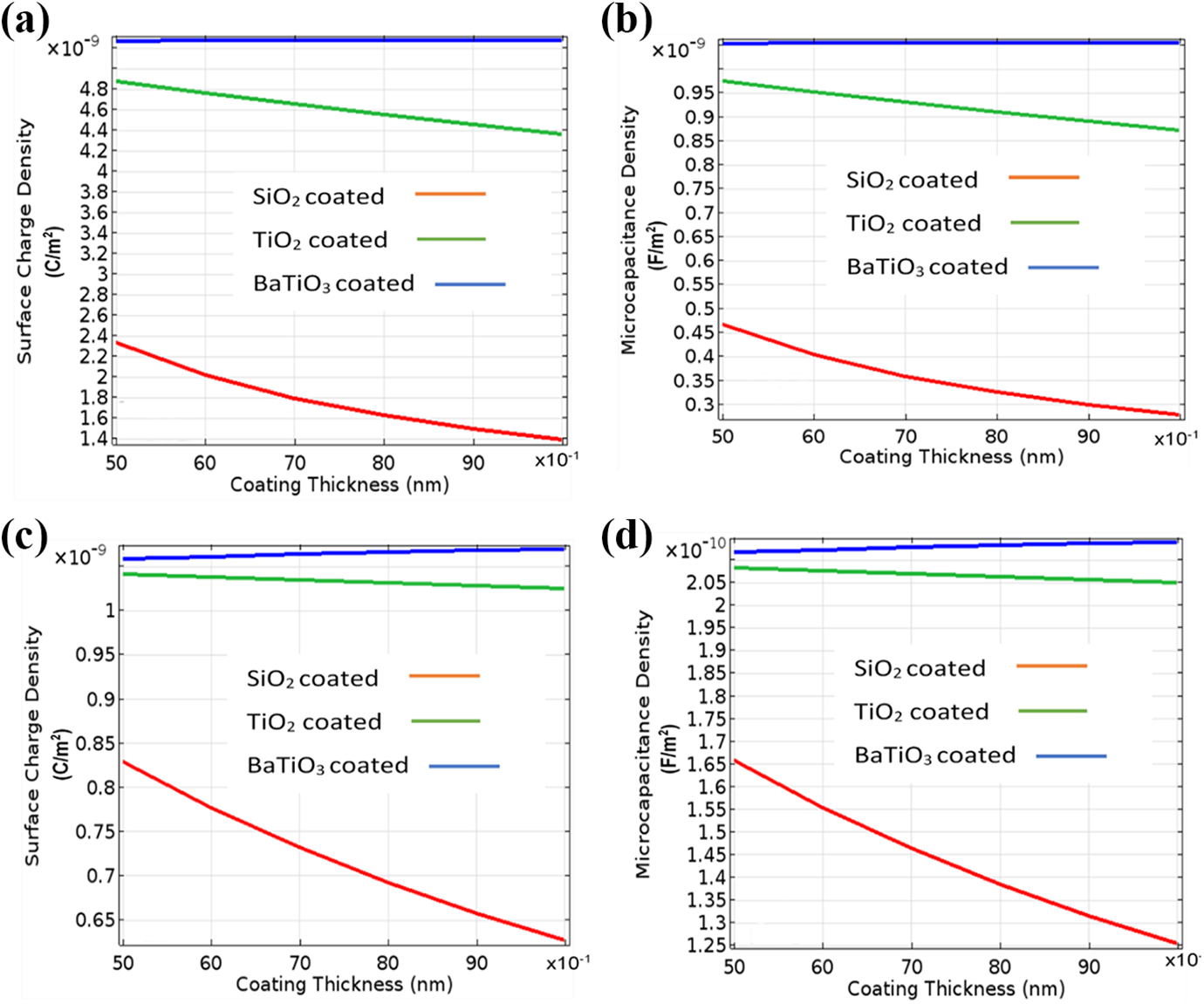
(a) Surface charge density and (b) microcapacitance density of the microcapacitors formulated within the PVDF matrix; (c) surface charge density and (d) microcapacitance density of the microcapacitors formulated within PP matrix.
Conclusion
This study has been able to simulate and investigate the effects of coating or insulating graphene nanosheets on localized voltage concentration and distribution in graphene–polymer nanocomposites using COMSOL Multiphysics. Various inorganic materials such as BaTiO3, TiO2 and SiO2, which have been repeatedly used by various studies in coating graphene nanosheets were considered with respect to their various dielectric constants. Various coating thickness of BaTiO3, TiO2 and SiO2 on graphene nanosheets were put into account. Two matrices (PVDF and PP) with different dielectric constant values were used as the simulation domain, with all the necessary boundary conditions applied. The results of the simulation showed that a lower dielectric constant coating material compared to that of a matrix is essential for a reduction in localized voltage accumulation and improve breakdown strength. This was noted in both voltage distribution around a single graphene nanosheet and voltage across polymer layers from one graphene nanosheet to another. Also, the simulation revealed that high coating thickness on graphene nanosheet is needed for a significant reduction in the localized voltage concentration of such nanocomposites. However, the conditions of low dielectric constant coating materials and high coating thickness resulted to decrease in surface charge and microcapacitance density with dependency on the coating thickness, especially with low dielectric constant coating materials. Therefore, this study suggests that for optimal energy storage density of insulated graphene–polymer nanocomposites, a compromise must be reached among the dielectric constant of the coating materials with respect to that of the matrix and coating thickness on the graphene nanosheets.
Footnotes
Acknowledgement
The authors appreciate the Centre for Energy and Electric Power and the Faculty of Engineering and the Built Environment, Tshwane University of Technology, South Africa for their financial assistance towards this work.
Funding
The author(s) received no financial support for the research, authorship, and/or publication of this article.