
Abstract
Laminar composites have widespread applications in the automotive and aircraft industry. This research was aimed to investigate the suitability of fused deposition modeling to produce multi-material laminar composites. Composites comprising of two dissimilar laminates, named as hybrid composites, were printed from acrylonitrile butadiene styrene filament and carbon fiber-reinforced polylactic acid filament (a composite filament) by varying different printing parameters. Tensile tests were conducted to examine the mechanical performance of the produced composite sheet. A detailed analysis of the results revealed that a high ultimate tensile strength is primarily achieved by setting low values of printing speed, layer height, and clad ratio while high elongation is obtained by employing low printing speed, medium layer height, and high clad ratio. The optimum printing conditions were sought out through desirability function with an objective to simultaneously enhance all the considered properties. Further, the composite sheet exhibited a reasonably good combination of tensile properties as compared to its monolithic constituent sheets. Based on the results, it is concluded that the bi-material laminating approach employed herein can produce printed structures with desired properties.
Keywords
Introduction
Three-dimensional printing (3-DP) that is technically known as additive manufacturing (AM) is a group of technologies that are evolving in the manufacturing field. AM is defined by the ASTM standards as “the process of joining materials to make parts from 3-D model data, usually layer upon layer, as opposed to subtractive manufacturing and formative manufacturing methodologies.”1–4 AM was introduced by Charles Hull in 1984, as a revolutionary fabrication technique.5,6 3-DP processes such as fused deposition modeling (FDM), selective laser sintering, selective laser melting, stereolithography, and laminated object printing are classified in AM technologies.7,8 Among these technologies, the most commonly adopted process is FDM.
AM offers certain merits over subtractive manufacturing such as less material consumption with less energy and time. The 3-D printed objects are used as prototypes, complex aerospace, and automobile components, in visual aids, physically functional parts, and models for educational presentations which covers almost 25% of the AM industry applications.9–13 According to Wohler’s report, 14 the aerospace industry is utilizing about 18.2% of the total AM market, and thus AM is positively anticipated to carry high potential perspective in the future. Additionally, FDM is showing great prospects for product development with the ability to contest against conventional polymer processing techniques. 15
Numerous engineering thermoplastic materials are available like acrylonitrile butadiene styrene (ABS), polylactic acid (PLA), polycarbonate, and polyphenylsulfone, which further expand the capability of the technique in terms of temperature and strength ranges. In the FDM technology, a flexible polymer filament is fed into a heated extrusion nozzle to melt the polymer filament. The layers are deposited on to a glass or metal plate in a layer by layer fashion in a specific raster pattern (i.e. a pattern comprising of parallel lines).16–19 The deposited polymer filament cures and hardens after extrusion from the nozzle and bonds to the layer below. Thus, the completed part can be considered as a vertically stacked layered structure with intermediate gaps leading to a variation in mechanical properties. 20 However, because of the limited availability of materials to be printed through FDM, the produced parts have limited applications due to relatively low mechanical properties.21,22 Therefore, to make this technology suitable for physically functional and load-bearing parts, FDM printable materials are needed to evolve into composite laminates to yield reasonable mechanical properties. Moreover, mechanical properties of materials and finished parts are used to identify the application of 3-D printed parts. For this purpose, printing parameters play a vital role in determining these core mechanical properties.23–25
Many researchers have investigated the effects of different printing parameters on mechanical properties of produced parts. Bartolo et al., 26 Carneiro et al., 15 and Rankouhi et al. 3 studied the effects of layer thickness on mechanical properties of ABS printed parts. Zhang 27 and Wu et al. 28 did their work on the printed ABS tensile test samples at 0°, 30°, +45/−45°, and 90° raster angle orientation. They concluded that the best tensile properties are depicted at 0° raster angle.
Ranjan et al.29,30 experimentally studied PLA-hydroxyapatite-chitosan (PLA-Hap-CS)-based biocompatible filament for FDM produced via twin-screw extruder. Tensile and flexural samples were tested with the dead weight of 12 Kg, 190°C barrel temperature and a screw speed of 140 rotations/min. They concluded that 0.2 mm layer thickness, raster angle of 30/45°, and 100% infill density were the best printing parameters for FDM.
Some studies reported the compatibility of aluminum-reinforced polyamide with ABS-based functional prototypes produced via FDM for friction welding and rapid tooling applications.31,32 Zhong et al. 17 investigated FDM printed parts with air gaps of −0.05 and +0.05 mm and found that parts with −0.05 mm air gaps show better results.
Dawoud et al. 33 compared FDM printed parts with injection-molded specimen. The results indicated that FDM printed parts become denser when printed with an air gap of −0.05 mm and hence perform better as compared to the specimen with positive air gap. Hwang et al. 34 investigated the effect of fill density on FDM printed parts and concluded that the tensile strength of specimen increased with an increase in infill density.
El Magri et al. 35 studied the influence of process parameters while comparing natural PLA and carbon fiber-reinforced PLA (CF-PLA). It was concluded that a lower cooling rate for annealing results in improved mechanical properties. Moreover, printing parameters like nozzle temperature and raster orientation along with the addition of reinforcing agent, significantly improve the tensile properties of FDM printed samples.
Kaynak and Varsavas 36 compared 3-D printed PLA and its elastomers with injection molded parts. Their study concluded that 3-D printed PLA and PLA/thermoplastic polyurethane elastomer (PLA/TPU) blend depicted overall best performance. However, it was pointed out that mechanical properties of PLA/glass fiber (GF) and PLA/TPU/GF parts tended to decline due to random orientation of reinforced GF.
For the FDM process these days, ABS and PLA are the most commonly used materials for 3-D printing applications. 37 Most of the commercially available 3-D printers can only print with these two materials. 28 Therefore, the FDM process parameters for these materials restrict the applications of FDM technology in the industrial sector. 38
Attempts have been made to extend the applications of FDM from a material perspective by mixing carbon fibers into thermoplastic polymer materials. This reinforcement of carbon fibers into polymer matrix could enhance the strength at the cost of toughness. This drawback, however, can be overcome by laying up layers of ductile polymer upon carbon fiber-reinforced polymer. The composite produced in this way may yield higher strength and toughness simultaneously. In the current study, the hybrid laminar composite sheets comprising of two polymers, ABS and CF-PLA, are fabricated through FDM. The fabrication was carried out by varying printing parameters to yield optimum tensile properties of ABS/CF-PLA hybrid composite sheet.
Materials and methods
The printing parameters that were investigated in this study include layer height, printing speed, infill density, and clad ratio. Layer height is the thickness or diameter of layer when it is extruded from the printing nozzle. Printing speed is the speed of nozzle with which it traverses over the printing bed. Infill density is the total amount of printing material inside the printed part and is measured in percentage. Clad ratio is the thickness ratio of two layers of different materials in the laminar composite. To fabricate composite, ABS and CF-PLA were employed as the parent materials. The ABS filament had a density of 1.07 g/m3, and the extrusion temperature and bed temperature for its printing were maintained at 230°C and 90°C, respectively, as recommended in the literature. 33 The CF-PLA filament had sufficiently small carbon fibers to easily pass through extrusion nozzle and long enough to provide added strength to the PLA matrix. The CF-PLA filament had 10% carbon by mass and 6% carbon by volume. The extrusion temperature of 200°C and a bed temperature of around 80°C were maintained while printing. Both ABS and CF-PLA stocks had the filament diameter of 1.75 mm. These two types of filaments were layered upon one another to fabricate a laminar composite, to be called as hybrid composite (H-composite) henceforth, in which both kinds of materials retained their identity and adhered together at the interface. The relative proportion (i.e. clad ratio) of the two materials was varied from 0.25 to 1.00 as shown in Table 1.
Clad ratio versus material percentage.
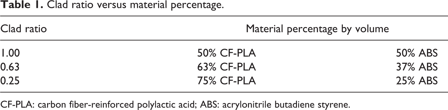
CF-PLA: carbon fiber-reinforced polylactic acid; ABS: acrylonitrile butadiene styrene.
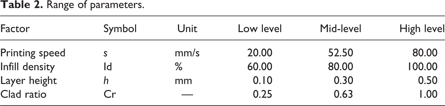
The design of experiment, a statistical approach, was applied to design the tests and analyze the results. Because, this approach contrary to ad-hoc approach, requires lesser number of runs to analyze the effects of various input parameters on a response variable. Also, in contrast to ad-hoc approach, it requires fewer replicates to estimate the accurate results and trends.39,40 Among various available methods, response surface method was employed for the current investigation as it estimates the individual and combined effects with a reasonably low number of runs without compromising the accuracy. The low and high levels of considered parameters are given in Table 2. These levels were selected in accordance with the permissible printer settings. The complete test plan comprised of 22 runs including 4 replicates, wherein each of the four parameters was varied over three levels (Table 3).
Range of parameters.
Experimental plan and tensile test results.
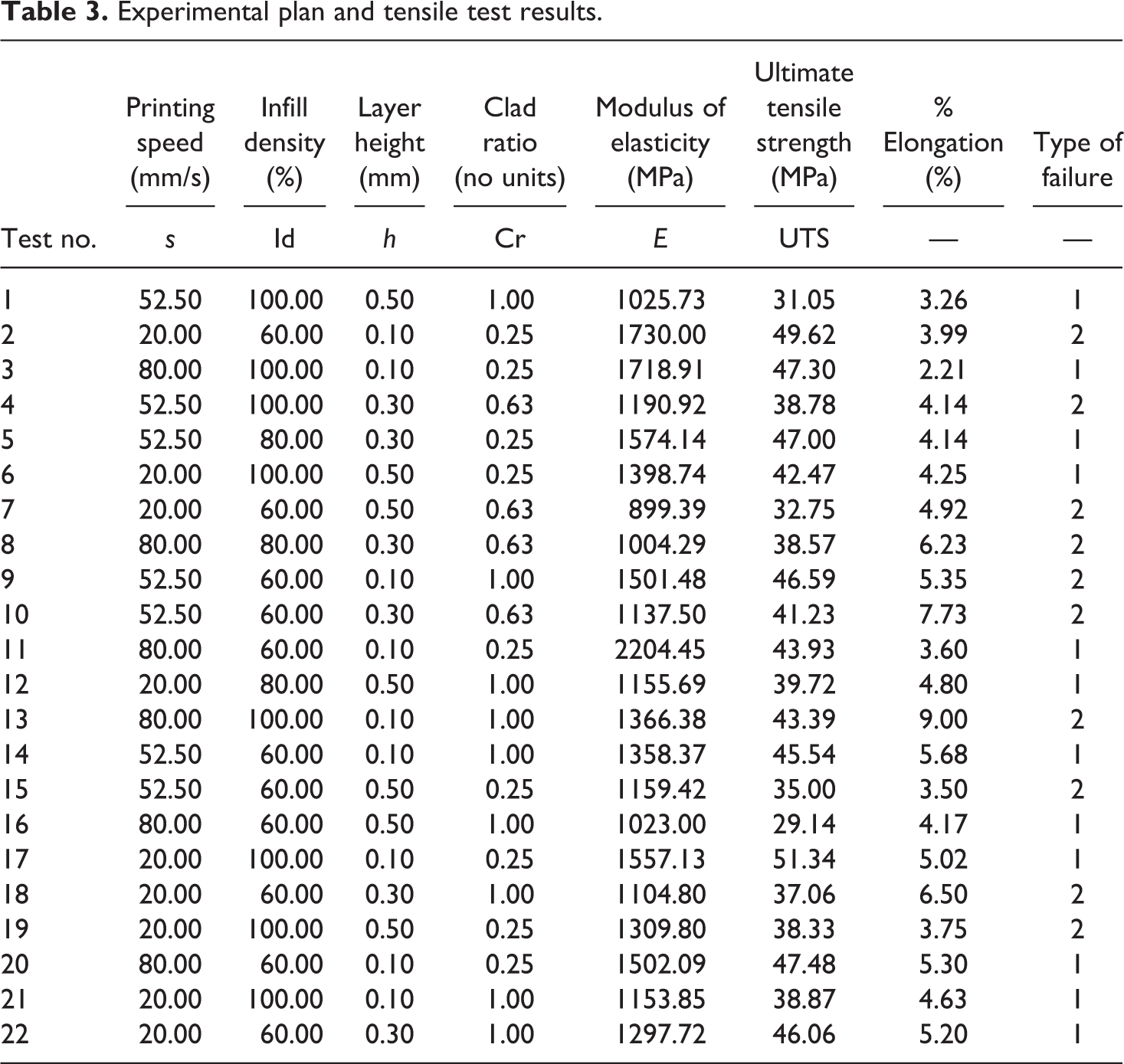
Figure 1 presents the print geometry. This is a tensile specimen with dimensions in accordance with the ASTM D638 Type IV. 41 The geometry model was drawn using the Creo modeling software. The stereolithography file of the model was exported to the printing software, which sliced the models into a series of layers according to the pre-defined layer thickness.
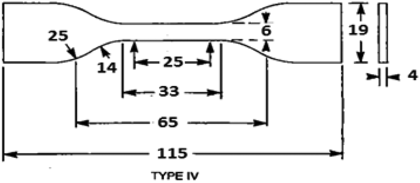
ASTM D638 test standard (Type IV).
The printing was carried out on the Xplorer 3-D printer shown in Figure 2. During printing, the following parameters were kept fixed: nozzle diameter = 0.75 mm, nozzle temperature = 210°C, and bed temperature = 90°C. Further, the raster angle was kept as 0° because this orientation according to the literature 28 offers the highest strength in comparison to 45° and 90°. The cumulative thickness in each tensile sample was ensured to be 4 mm in accordance with the ASTM standard D638-02. 41
Xplorer 3-D pro printing the samples.
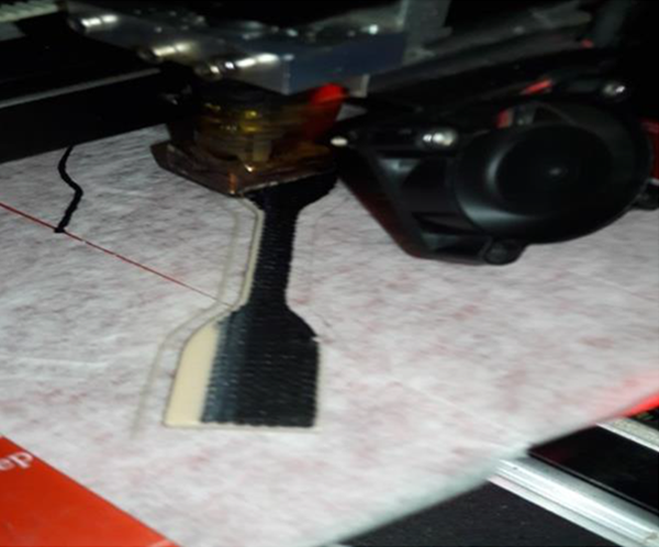
To print the bi-material composite sheet, initially ABS laminate was printed on the printing bed until the pre-defined thickness was achieved. Then, the ABS filament was instantly replaced with the CF-PLA filament without any pause in the material supply as shown in Figure 3. Table 4 lists the layer number for transitioning of material: this estimate was based on the slicing of model. Upon transitioning, the new material fused onto the previous material thereby forming a strong interfacial bond.
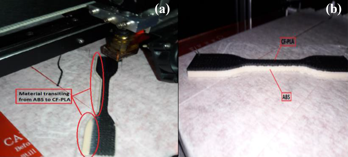
Tensile test sample.
Material transition against various clad ratio.
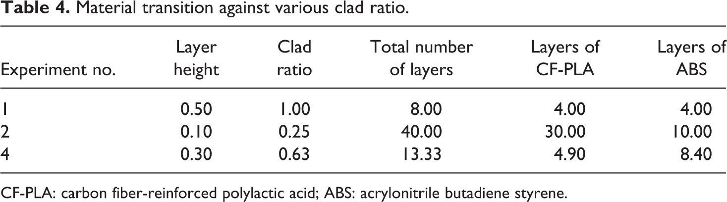
CF-PLA: carbon fiber-reinforced polylactic acid; ABS: acrylonitrile butadiene styrene.
Tensile tests were performed on an ultimate tensile testing machine having a capacity of 30 kN load. The strain rate during testing was maintained at 2 mm/min. The analysis of the fractured specimens was carried out with a scanning electron microscopy (SEM) (MIRA3 TESCAN).
Results and discussion
Table 3 presents the tensile properties of 22 hybrid composite sheets. As observable from the table, the elastic modulus ranges from 899.39 to 2204.45 MPa. The tensile strength ranges from 29.14 to 51.34 MPa, and the percentage elongation ranges from 2.21% to 9.00%.
Figure 4 compares the stress–strain behaviors of composite sheet and monolithic sheets. The monolithic sheets were fabricated from each of ABS and CF-PLA parent materials. Printing was performed using the conditions as given in Test 21. As can be noticed from Figure 4, the hybrid composite sheet has a significantly greater ultimate strength than the constituent monolithic sheets. As regards the elongation, the composite sheet has a greater elongation than the CF-PLA monolithic sheet whereas lower than the ABS sheet. This findings indicates that optimum laminating in terms of materials and conditions can lead to a situation that results in desired tensile properties.
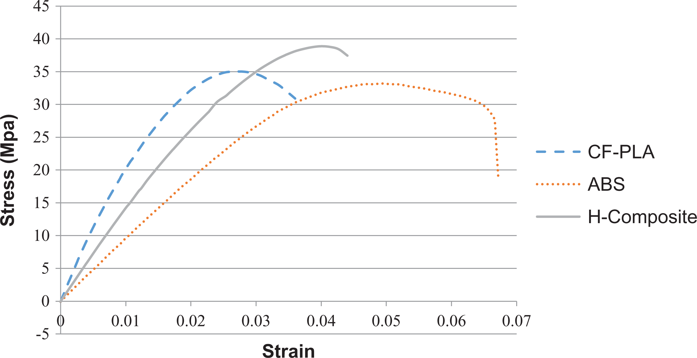
Comparison between parents and composite material.
From an in-depth examination of the composite specimens, two failure modes were identified. In the first type of failure (Type-I), most samples fractured in a catastrophic manner without any delamination as evidenced in Figure 5. While in the second type (Type-II), the failure initiated with delamination at the ABS/CF-PLA interface followed by fracturing of ABS laminate (Figure 6). Out of 22 specimens, 12 specimens failed according to the Type-I failure while 10 specimens witnessed the Type-II failure.
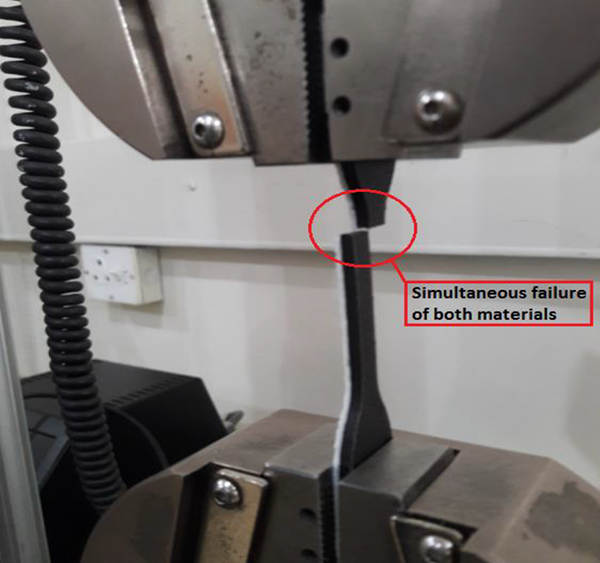
Type-1 failure.
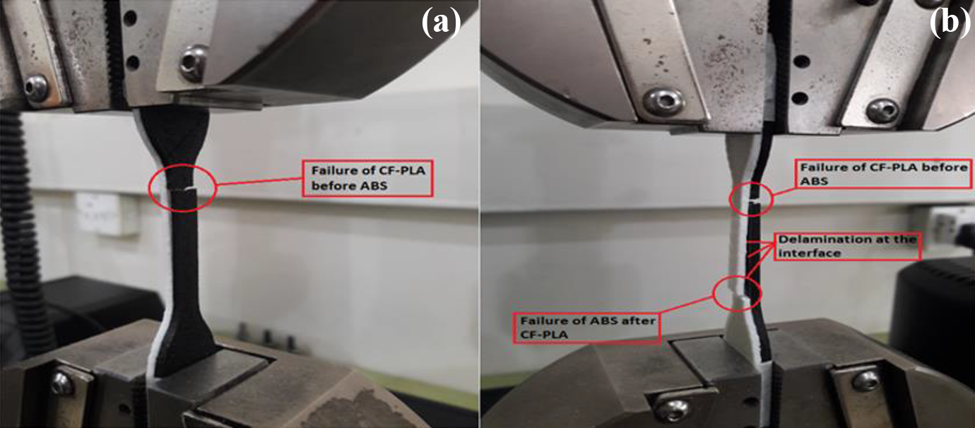
(a) Type-1 failure and (b) Type-2 failure.
Selected stress–strain curves representing Type-I failure are shown in Figure 7. The stress increases with strain and fracture occurs upon attainment of a peak stress. Most of the composite samples that failed under Type-I were printed employing the layer thickness of 0.1 mm. This follows that the likelihood of Type-I failure in printed composite sheets is high when the layer thickness is 0.1 mm. This seems to be logical because interlayer cracking occurs due to repeated thermal cycles, when the layer thickness is excessively low, 42 thereby increasing the possibility of sudden fracture during service.
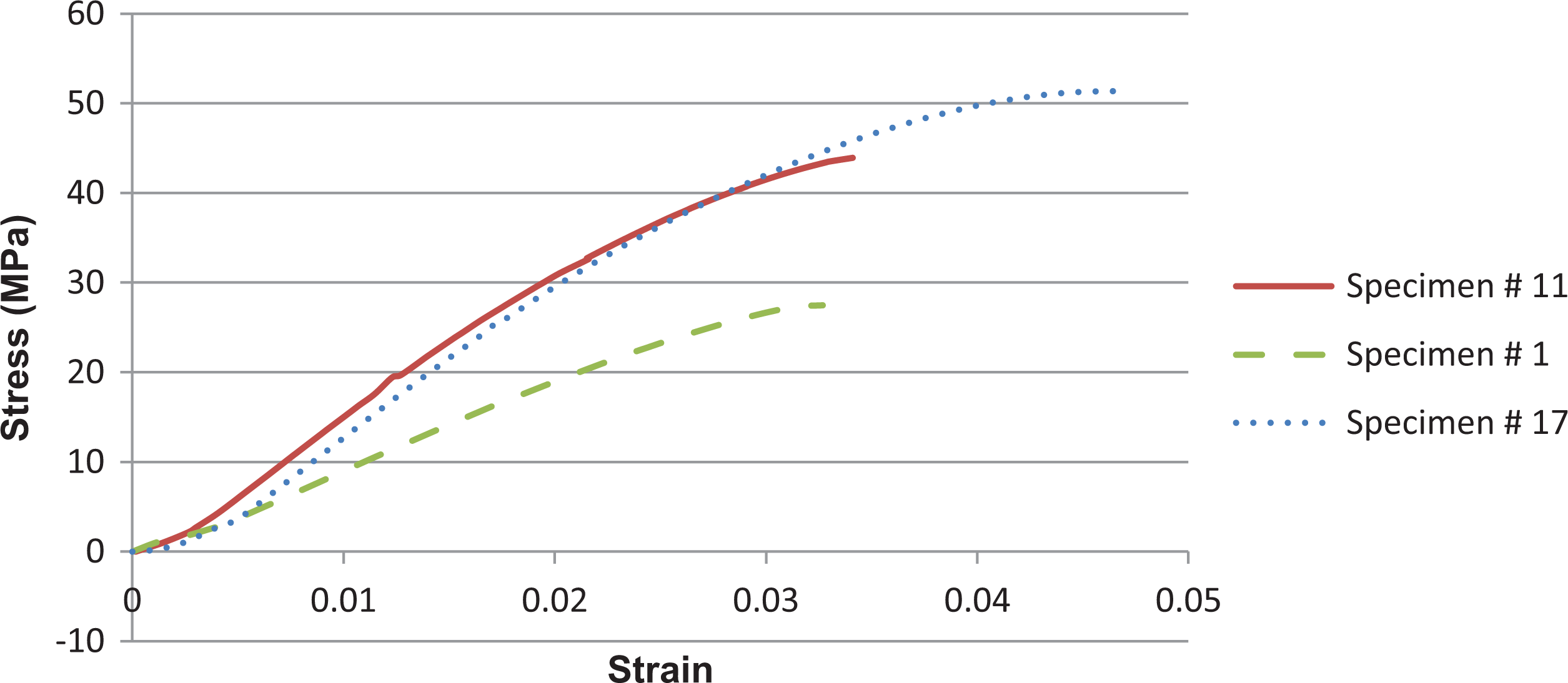
Type-1 failures.
Figure 8 presents selected stress–strain curves representing Type-II failure. As observable from the curves, the stress remains proportional to strain till both the laminates in composite sheet remain intact. However, once the CF-PLA laminate delaminates, the overall load carrying capacity of the composite sheet decreases drastically finally leading to fracturing of the ABS laminate. A close scrutiny of the failed samples highlighted that most of the samples those followed the Type-II failure had been printed with fill density of 60% thereby implying that printing with low fill density increases the likelihood of Type-II failure in the composite sheets. This can be reasoned to a fact that printing with low infill density leads to an increased porosity along with high air gap between each two successive beads. Consequently, the bonded area at the laminates interface decreases thereby augmenting the chances of interfacial delamination during loading.
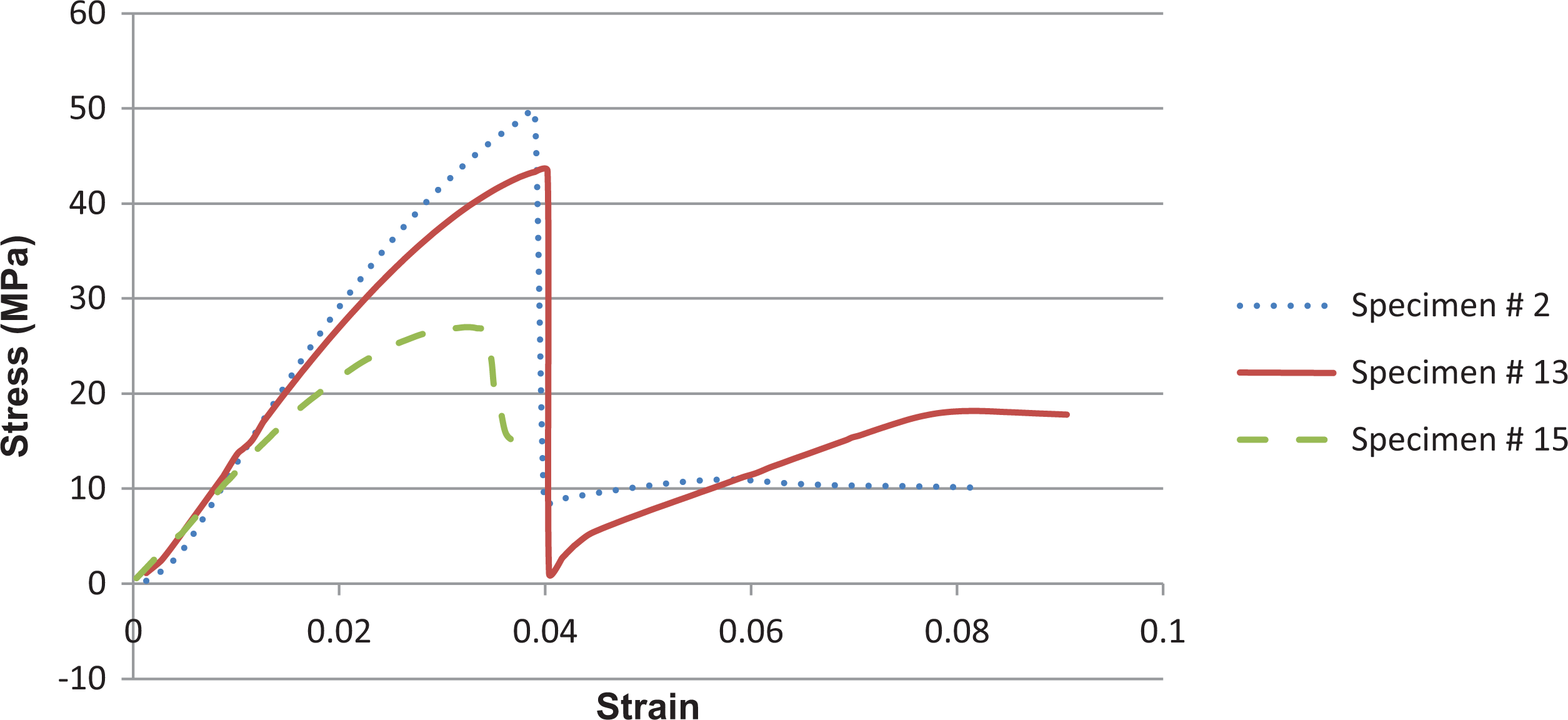
Type-2 failures.
It was observed that 6 out of 10 composite samples following the Type-II failure had a high proportion of CF-PLA (i.e. >63%). The CF-PLA is brittle in nature and tends to break at low strains while ABS is ductile in nature with ability to withstand larger strains. This discrepancy in the plastic behaviors of the two bonded laminates can consequently cause slippage at the interface (relative motion between the laminates) thereby causing delamination during tensile loading.
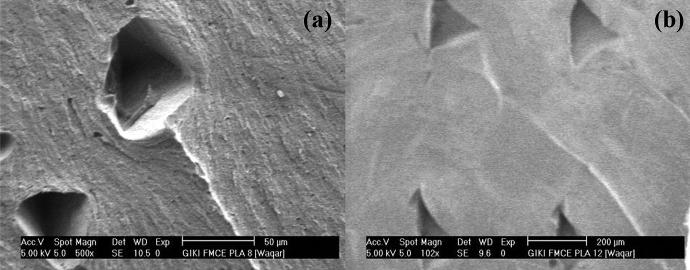
Figures 9 and 10 show the SEM fractographs of sample 8 and sample 12. This is to observe from Figures 9(a) and 10(a) that cavities formed in CF-PLA laminate of the composite sheet whereas such cavities were not formed in the ABS laminate. The formation of cavities in CF-PLA laminate leads to its premature failure as compared to failure in the ABS laminate. The cavity formation occurs due to carbon fiber pull out when the composite sample is subjected to tensile loading, which serves as sites of crack initiation and coalescence. Comparison between the fractured surfaces of CF-PLA and ABS laminates (Figures 9 and 10) reveals that the cavities density is lower in the ABS laminate than that in the CF-PLA laminate. This implies that the ABS laminate has stronger intra-layer bonding than the CF-PLA laminate.
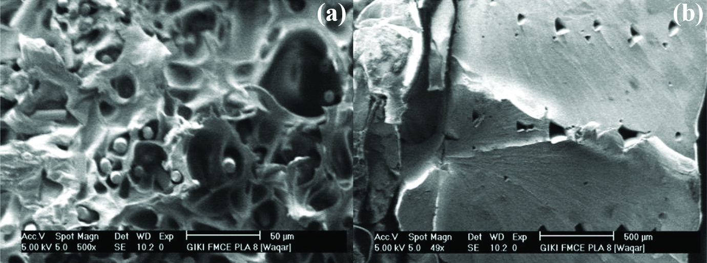
(a) SEM images of fractured surface of sample #8 CF-PLA portion and (b) ABS portion.
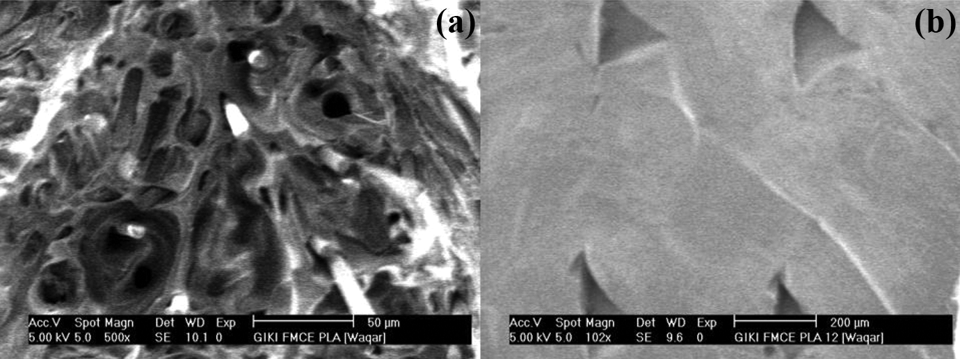
(a) SEM images of fractured surface of sample #12 CF-PLA portion and (b) ABS portion.
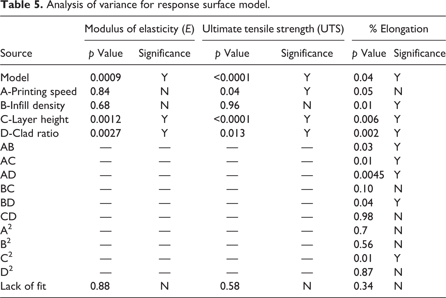
The significant printing parameters were identified through conducting the analysis of variance (ANOVA). The ANOVA for three tensile properties, that is, modulus of elasticity, ultimate tensile strength (UTS), and percentage elongation, is presented in Table 5. A parameter is considered significant when the respective p ≤ 0.05 or in other words the confidence level is 95%. According to the analysis results, the layer thickness and clad ratio are significant parameters for all of the three tensile quantities. In-fill density is significant only for elongation, and printing speed is significant only for ultimate strength. Further, certain cross-interactions are also significant and these effect the elongation only thereby revealing that this particular property depends on the combined effects of parameters. The lack of fit in each response model has p > 0.05, which means that the lack of fit is insignificant and the model can interpolate between each two design points. From analysis, standard deviation was also determined for each of the modulus of elasticity, UTS and percentage elongation. Its value was respectively estimated to be 0.31, 0.095, and 0.24 thus showing that the dispersion was low and the results had good repeatability.
Analysis of variance for response surface model.
Figures 11 and 13–15 depict the effect of significant parameters on different tensile properties. Figure 11 shows that the layer height and clad ratio significantly affect the modulus of elasticity. The modulus linearly decreases with increasing either of these two parameters. In fact, the air gap increases with the layer height; for instance, the gap increases from 10 to 125 µm as the layer height increases from 0.1 to 0.5 µm as given in Table 6 and evidenced in Figure 12(a) and (b). As a result, the composite density decreases thereby resulting in reduced modulus. 43 As regards the clad ratio, an increase in its value correspondingly increases the ABS proportion (it has lower modulus than CF-PLA) consequently causing a proportional reduction in the overall modulus of composite sheet.
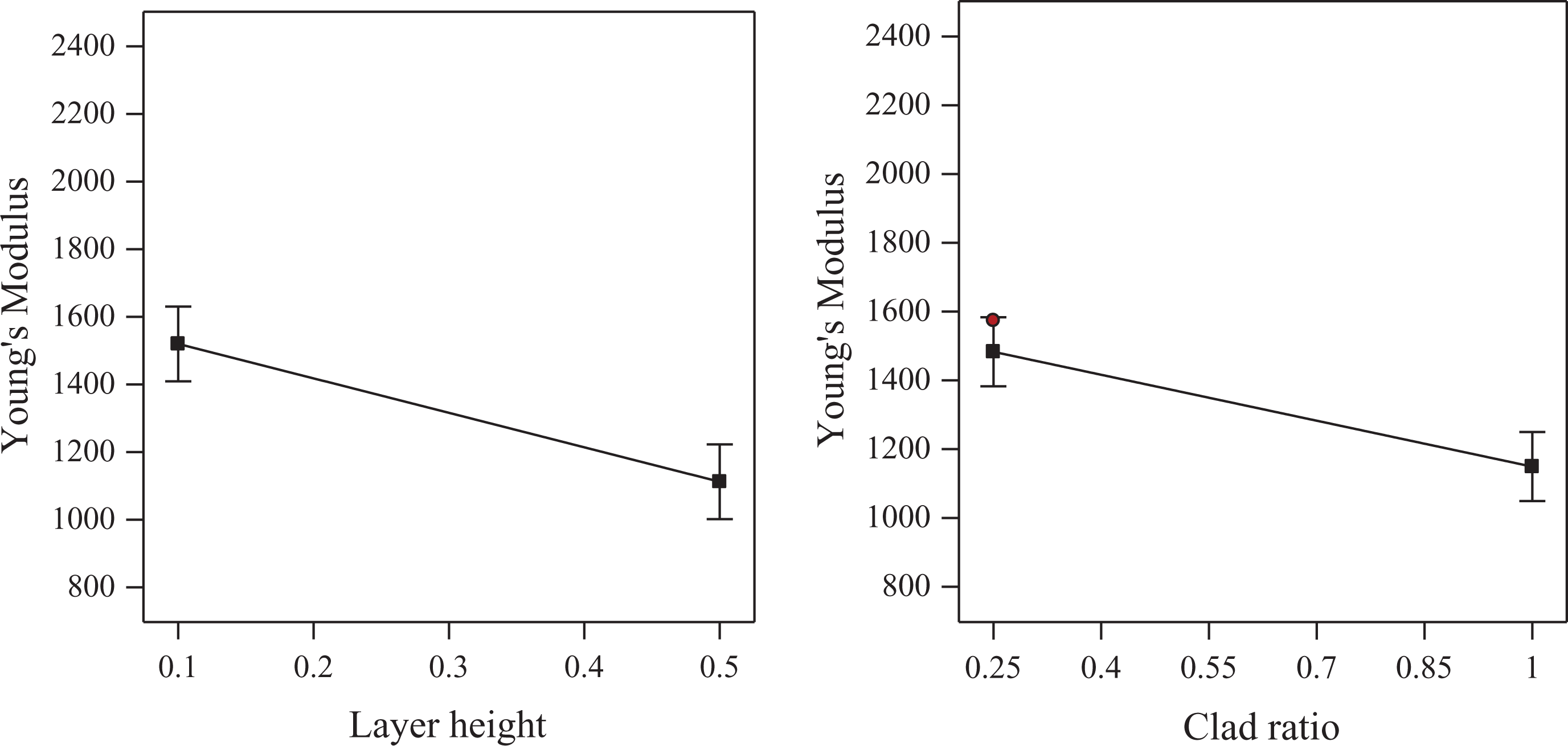
Effect of printing parameters on E.
(a) Sample 8 and (b) sample 12.
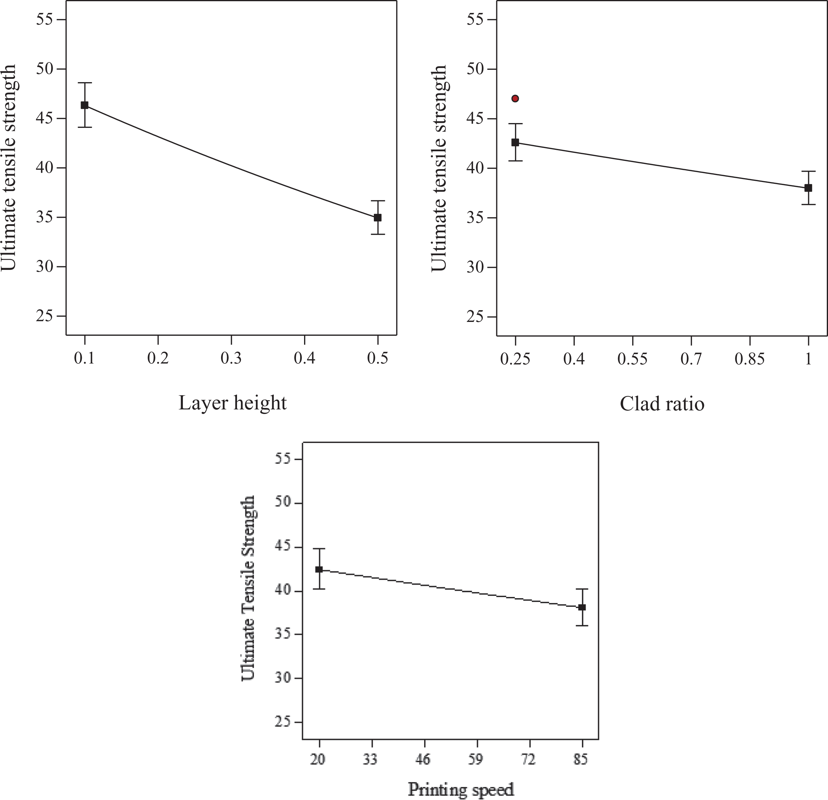
Effect of printing parameters on UTS.
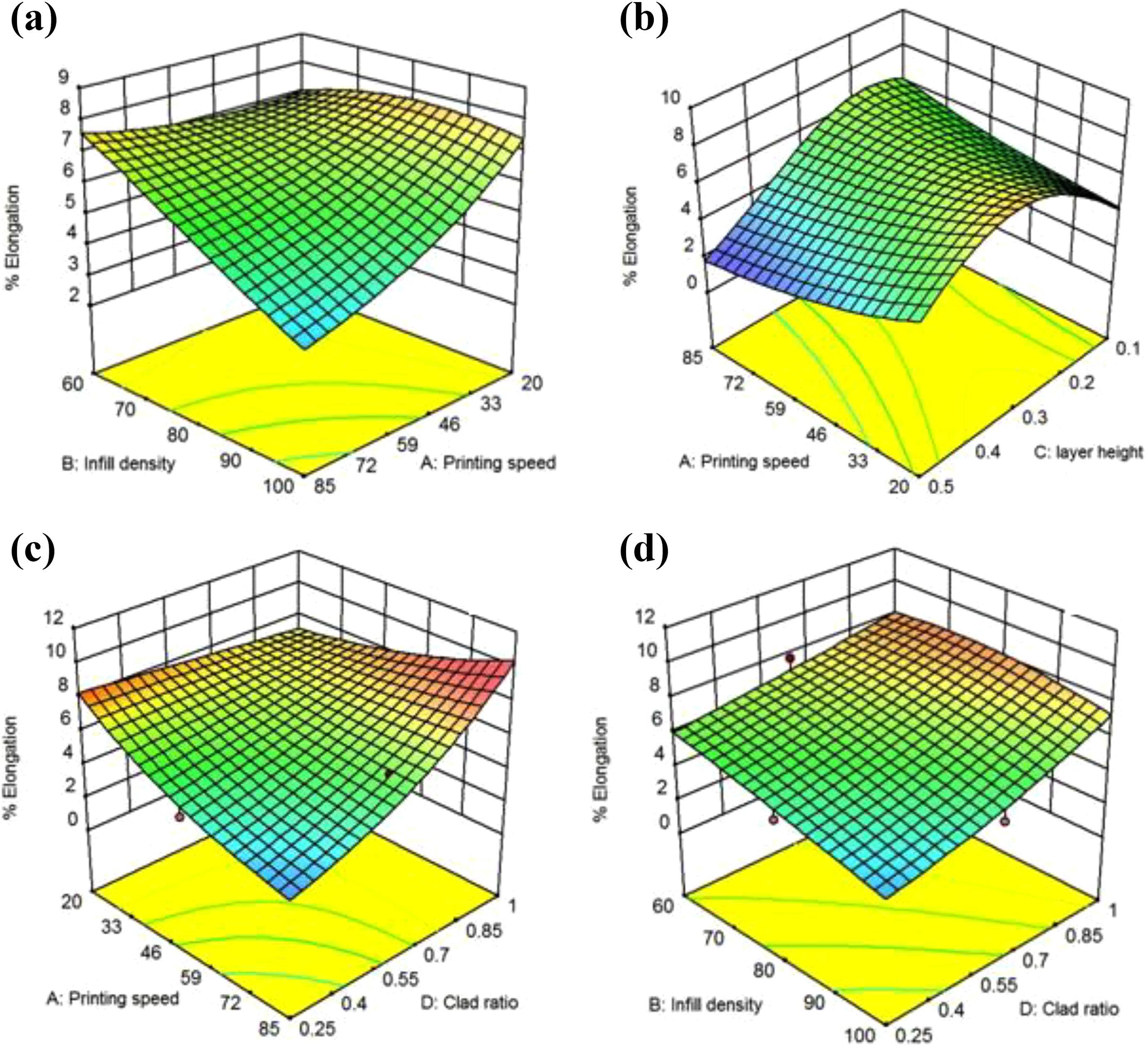
Effect of (a) Infill density and printing speed; (b) Printing speed and layer height; (c) Printing speed and clad ratio; and (d) Infill density and clad ratio on % elongation.
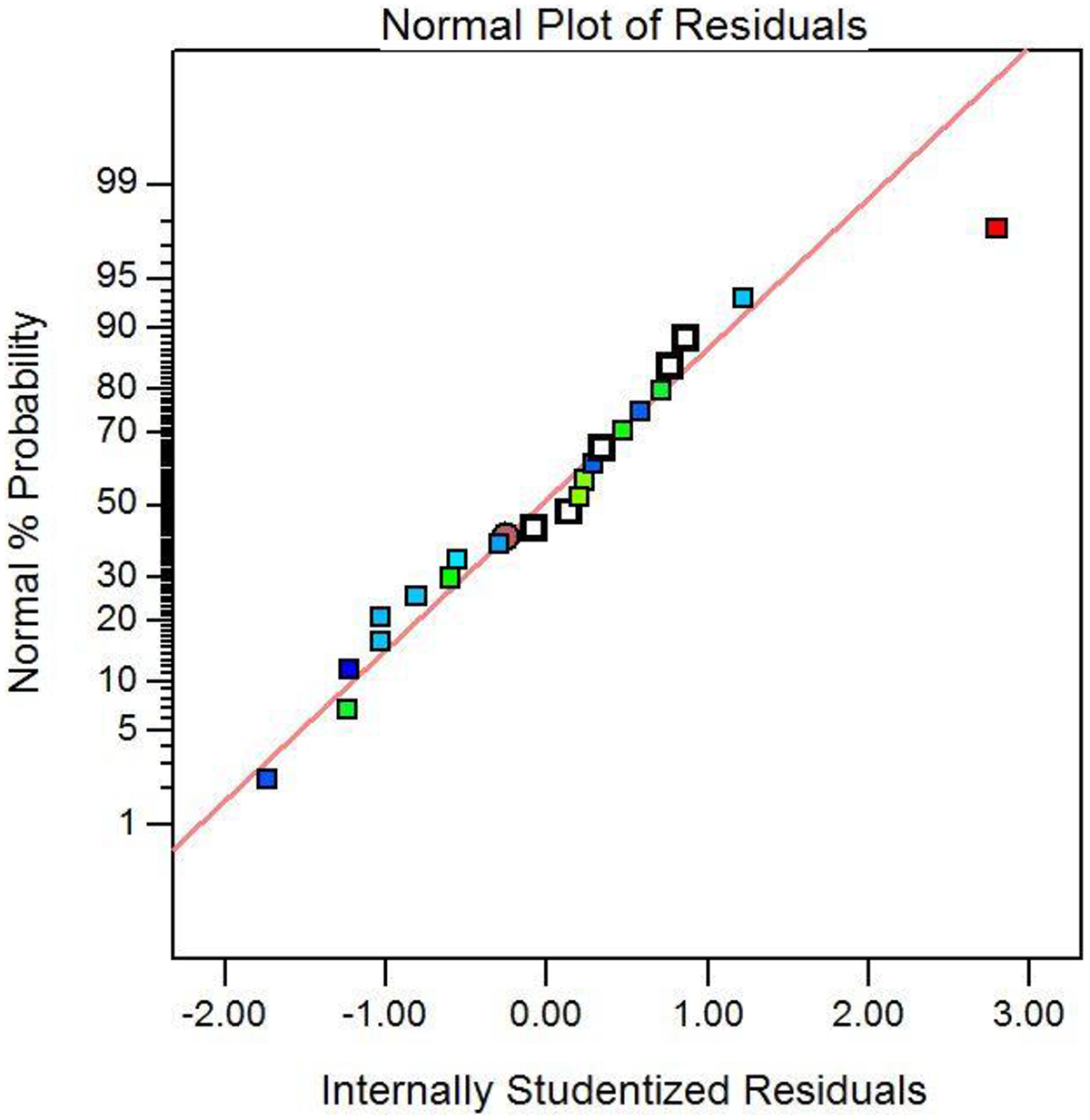
Internally studentized residuals.
Comparison between layer height and air gap of representative specimens.
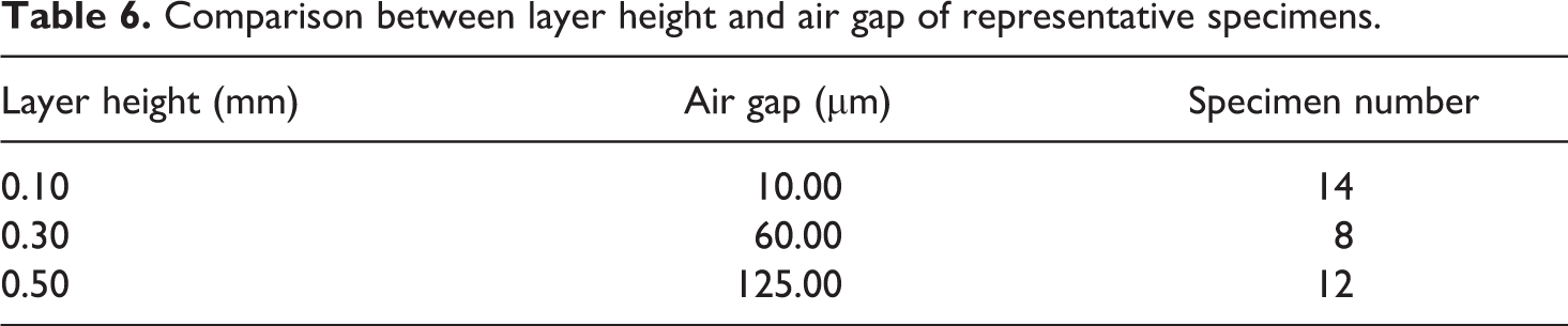
Figure 13 plots ultimate strength as the function of influential parameters namely layer height and clad ratio. The ultimate strength gradually reduces with increasing the layer height and clad ratio. From the slopes of graphs, it can be observed that layer height is a more influential parameter than clad ratio. This worth noticing from Figures 11 and 13 that the nature of these two effects for the elastic modulus and ultimate strength is alike. Moreover, the causes of these effects are also alike as witnessed from the microscopic analysis of the samples explained earlier. Similar to other effects, higher printing speeds also cause a reduction in the ultimate strength. This might be due to insufficient interlayer fusion at high speeds. 44
Figure 14(a) to (d) portrays the influence of significant parameters on % elongation. It decreases with increasing the infill density, regardless the interacting clad ratio is low or high (Figure 14(d)). Its response to infill density is, however, affected by the selection of printing speed (Figure 14(a)). It decreases with an increase in the infill density when the printing speed is high (say 80 mm/min). This trend, however, gradually changes as the printing speed reduces. For example, at printing speed of 20 mm/min, the elongation initially increases with increasing the fill density (from 60% to 80%) and then decreases onwards. The effect of printing speed on % elongation is also interactive in nature. As observable from Figure 14(a) to (c), the elongation decreases with printing speed when printing is performed using high infill density (100%), high layer thickness (1 mm), and low clad ratio (0.25). However, a contrary effect is observed, when layer thickness is low (0.1 mm) and clad ratio is high (1.0). Regarding the effect of layer thickness, elongation initially increases with increasing the layer thickness (say from 0.1 mm to 0.3 mm) followed by a decrease. The elongation generally increases with increasing the clad ratio reasoning to respective increase in the ABS proportion, but an exception also occurs when the printing speed is low (say 20 mm/min).
Comparing Figures 11 and 12 with Figure 14, it can be noticed that elastic modulus and ultimate strength are in partial opposition with the elongation in respect of parameters effects. Further, one needs to employ larger values of printing speed, clad ratio, and printing speed to achieve high elastic modulus and ultimate strength of composite. However, in case elongation is the primary objective, low density, middle layer thickness, high clad ratio, and high printing speed should be employed to print the composite.
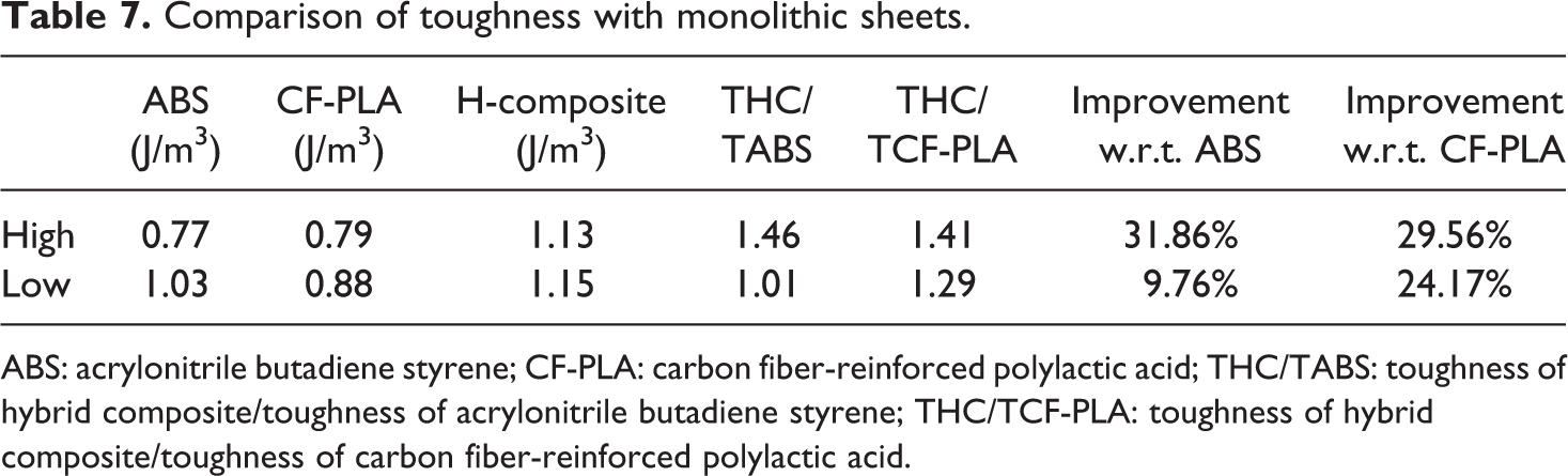
Table 7 compares the toughness of hybrid composite sheet and constituent monolithic sheets for two extreme levels. It can be noted down that the toughness of hybrid composite sheet in both cases is interestingly greater (24–30%) than those of the monolithic sheets. This means that laminating of different materials into a composite sheet is an attractive approach to realize materials with enhanced toughness in addition to increasing the strength.
Comparison of toughness with monolithic sheets.
ABS: acrylonitrile butadiene styrene; CF-PLA: carbon fiber-reinforced polylactic acid; THC/TABS: toughness of hybrid composite/toughness of acrylonitrile butadiene styrene; THC/TCF-PLA: toughness of hybrid composite/toughness of carbon fiber-reinforced polylactic acid.
The various effects on each tensile property discussed earlier can be combined into respective hyper-surfaces through empirical models. For this purpose, regression analysis was performed using the DX-software, which proposed the following models:


where s is printing speed, Id is infill density, h is the layer height, and Cr is the clad ratio.
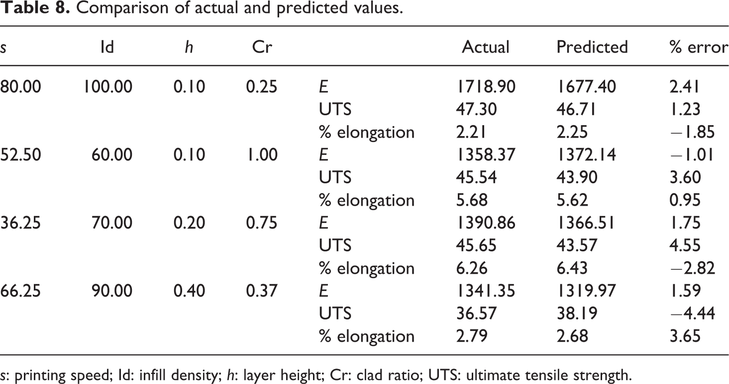
Two tests namely normal distribution and R-squared (R2) value were performed to examine the fitness of above models. As shown in Figure 15, the residuals follow a normal distribution. Moreover, the value of R2 is found to be high (>80%). These tests suggest that models are fit for use. The models were further validated by conducting experiments and comparing the experimental and predicted results against four sets of given conditions. The results are shown in Table 8. As given in table, the percentage error in the experimental and predicted values is within the acceptable range (<5%), which validates that the proposed models are accurate and can be employed to predict the tensile properties of the produced composite within the investigated range of parameters.
Comparison of actual and predicted values.
s: printing speed; Id: infill density; h: layer height; Cr: clad ratio; UTS: ultimate tensile strength.
As discussed earlier, the tensile properties are in mutual opposition with respect to the effects of parameters. In case, all of the properties are important for an application, one needs to fabricate composite with an optimum set of conditions that can provide a trade-off among them. With this objective, optimization was performed using desirability approach in the DX-software. After undergoing several interactions, the following solution was proposed: printing speed = 20 mm/s, infill density = 67.838, layer height = 0.23, and clad ratio = 0.25. This solution is intended to produce a composite with the following properties: modulus of elasticity = 1552.9 MPa, UTS = 47.15 MPa, and % elongation = 7.75%.
Conclusion
The FDM printing process was employed to produce a series of hybrid composite sheets. Two types of filaments (i.e. ABS and CF-PLA) and four printing parameters were employed to fabricate the composite. The following are the important findings: The printed composite sheet shows greater ultimate strength than the constituent monolithic sheets. This suggests that the laminating approach applied to produce composite sheet has potential to fabricate functional components with desired properties. A variation in the printing parameters affects the mechanical properties of the hybrid composite (ABS/CF-PLA). High UTS is achieved employing low values of printing speed, layer height, and clad ratio. These conditions also yield high modulus of elasticity. However, high elongation is obtained when printing is performed with high printing speed, medium layer height, and high clad ratio. The peak properties as collected from different printing combinations are: elastic modulus = 2204.45 MPa; ultimate strength = 51.34 MPa; and elongation = 9%. Layer height and clad ratio have significant effects on all of the considered tensile properties. Printing speed affects only ultimate strength and infill density affects only elongation. The optimum set of printing conditions that offers a trade-off among various considered tensile properties are as follows: speed = 20 mm/s, infill density = 67.838%, layer height = 0.23 mm, and clad ratio = 0.25. Two types of failure modes are observed when the composite sheet is subjected to tensile loading. In Type-I, failure occurs due to simultaneous fracture of constituent laminates of composite. The Type-II failure, however, initiates with the fracture of CF-PLA laminates followed by delamination at the CF-PLA/ABS interface.