
Abstract
Due to the introduction of highly restrictive safety and pollution legislations in the railway industry, weight reduction has become an increasingly important topic over the last decade. Carbon fibre-reinforced polymers (CFRPs) constitute an excellent alternative to traditional materials, due to their highly specific in-plane mechanical properties. Their use in railway industry, however, is currently hindered by their weak out-of-plane properties. Bogies and underframes are often subjected to impact loadings caused by objects and debris surrounding the tracks (i.e. ice, ballast) that become airborne during the train transit and impact lower part of the carriage. While metal structures absorb impact energy via plastic deformation, barely visible impact damage can occur in CFRP, weakening the component, and often leading to catastrophic failures. This work proposes a method for the improvement of impact absorption performance of railway composite structures via the addition of a thermoplastic polyurethane (TPU) coating to CFRP laminates. The thermomechanical behaviour of the thermoplastic layer was investigated with dynamic mechanical analysis and differential scanning calorimetry analysis to optimize the manufacturing process, while damping tests were carried out to demonstrate its unaltered energy absorption ability in the final manufactured structure. TPU/CFRP plates (150 × 100 mm2 of in-plane size) were subjected to 2, 3 and 5 J impacts, and the results were compared with those of traditional CFRP laminates. Non-destructive test (NDT; i.e. C-scan, phased array) and compression-after-impact test were carried out on the impacted samples to assess the damaged area and residual in-plane mechanical properties. Results show that the TPU layer modifies the energy absorption mechanism, preventing the propagation of damage within the CFRP and resulting in undamaged samples even at the highest energy. To predict the TPU/CFRP impact behaviour and identify the best process parameters to optimize impact energy absorption, a finite element model was developed and validated using experimental data. The comparison showed good correlation, and a fine approximation of the different impact mechanisms was observed with a maximum error of 5% between experimental and simulated output values. The experimental and numerical results show that the TPU/CFRP laminates constitute a novel solution for the manufacturing of lighter and safer railway composite structures.
Keywords
Introduction
Over the last 20 years, the mass of rail vehicles has increased by more than 35% due to the technological improvements in structures, subsystems and apparatus necessary to comply with market demands and higher safety requirements (EN 12663, CEN-EN 15227). Indeed, increased comfort requirements pushed manufacturers to install on rail vehicles more complex facilities, such as air-conditioning systems, noise and vibration insulations and media devices to improve the quality of the journey. At the same time, as a consequence of safety legislation strengthening, railway vehicles became more complex and several mechanical systems, such as brakes and crash boxes, increased their size and weight to satisfy higher performance demands. Heavier trains require greater drive power, and therefore, railway industry developed larger and heavier motors (electric or diesel) which, in turn, need stiffer and more resistant bogies to withstand stresses caused by larger dynamic solicitations. In addition, higher velocity demanded changes in structures such as windows, doors and front cabs, causing an additional weight component for the entire rolling stock due to higher stiffness and more complex geometries necessary to comply with the standards.
All these additional systems and the increased mass of structural component negatively affected the economy of railway industry, leading to a rise in production costs, higher energy consumption, larger amount of CO2 emissions and greater track wear.
In this context, railway systems require a new technological approach to fabricate lightweight structures for train vehicles, also considering that several railway track providers, such as UK Network Rail, set up their network usage contract charges on the mass of the vehicles to reduce the track consumption and renewal costs. 1
To meet the low mass requirement, the use of composite materials in railway structures and components can represent an excellent solution to reduce the global weight of the train structure while keeping the same mechanical properties in terms of stiffness and strength.
In general, major mass distribution in rail vehicles, as stated by Euro Transport Consult, 2 is located in motor bogies, motors and drives (22%), car body (21%), interiors (17%) and trailer bogies (15%). Therefore, it is clear that by using composite materials in primary structures, it is possible to not only reduce weight by 20–40% 3 but also lower maintenance costs due to the higher corrosion resistance typical of composite materials. 4,5 Lighter car bodies would also need less power and braking equipment, leading to a reduction of the rotating masses, with an overall mass reduction, considering that a traditional high-speed train brake disc weighs around 100 kg. 6
Composite materials in railways have already been used for interior applications (seats, panels and secondary structures), but only in recent times, some structural applications have been proposed such as the glass fibre-reinforced polymer (GFRP) bogie realized and tested by Goo et al. under different loading conditions 7 and the front cab sandwich shock absorber designed and simulated numerically by Grasso et al. 8 By applying fibre-reinforced polymers in the primary structures, Siemens developed a lightweight train, reducing the mass per seat value by 34% (357 kg) compared with the previous-generation trains. 2 Heller et al. manufactured a hybrid body railway vehicle using GFRP sandwich composites for both sidewall and ceiling panels, achieving a mass reduction of almost 20% in comparison with a traditional stainless steel body. 9 Similarly, CG Rail recently produced a rail vehicle made in large part (around 70%) of composite components, developing a manufacturing process capable of producing large carbon fibre-reinforced polymer (CFRP) profiles with a wall thickness up to 25 mm. The total mass reduction in comparison with an aluminium car body vehicle is almost 30%, due to a 90% CFRP content in main large structures such as front cab and under-floor panelling. 10
Although the studies mentioned above prove that composite structures are making some headway in the railway industry, one question that still needs to be asked, however, is whether composite components would be able to fully substitute traditional metal structures despite their weak resistance to loads in the out-of-plane direction. Indeed, it is well known from the aerospace sector that detriment of mechanical properties caused by impact events 11 is the principal critical limitation to the implementation of the composites in primary load-bearing structures. Referring to the specific case of railway industry, Onder et al. 12 assessed the damage caused by impact loadings on E-glass/polyester laminate structures and pointed out the effects of impacts at four velocity levels (40, 70, 100 and 130 m s−1). Goo et al. 7 evaluated the structural integrity of a bogie frame, made of glass/fibre epoxy 4-harness laminate subjected to impacts at three different energy levels (5, 10 and 20 J), showing a detriment of residual properties by almost 18%, with an increased damage area at higher energy levels and for sharper edges of the impacting object.
The issue of impact resistance is of fundamental importance for railway components due to flying ballast projections, 12 a phenomenon for which general objects such as debris, leaves and ice become airborne due to aerodynamic and mechanical causes and impact the bottom portion of the vehicle in transit causing damage. These impacts, generally characterized by a minimum energy level of around 5 J, 7 can generate barely visible impact damage (BVID) to composite components, leading to a detriment of mechanical properties in terms of strength and stiffness 13 –15 that can result in unexpected failure of the component, exposing the entire structure and passengers to serious dangers.
Hence, to fully exploit the intrinsic lightness of composite materials within the railway sector, new approaches are constantly investigated to enhance their out-of-plane properties without losing the desired in-plane characteristics. Riccio et al. demonstrated the effectiveness of optimizing the laminate layup and skin thickness to minimize the delaminated area during composite failure and improve its resistance against out-of-plane dynamic loading. 16 In addition, the same authors investigated impact resistance improvement in composite panels via the use of selective stitching to prevent skin–stringer debonding showing superior mechanical properties in comparison with reference. 17 Rechak et al. inserted adhesive layers between cross-ply graphite/epoxy laminates and found that the polyamide epoxy adhesives are able to toughen the interfaces between laminate increasing absorbed energy due to increased contact area (+40%) and reducing matrix cracking. 18 Siegfried et al. studied the effect of carbon nanotubes (CNTs) on woven carbon fibre/epoxy composites and evaluated that CNTs improved mode II inter-laminar fracture energy (+22% compared with the reference material) and damage tolerance of composite, but they also increased their sensitivity to the onset of matrix cracks with a larger delamination area after impact. 19 Ruggeri et al. demonstrated a significant increase in impact damage tolerance for composite fan blades applying thermoplastic polyurethane (TPU) interleaved layers, observing no delamination in the interleaved region. 20 Following a similar approach, Martone et al. developed a damping behaviour model for TPU-interleaved composite and reported an improvement in terms of dynamic response towards low velocity impact (LVI) events when the interleaved layers are inserted symmetrically within the laminate’s stacking sequence. 21 Russo et al. instead proposed a woven glass fibre/TPU composite that showed no delamination after impact (even at low temperatures and for thick plates); however, increasing the thickness of the laminates, the effect of the interleaved layers loses its efficiency as an increased crack initiations tendency was recorded. 22
Although these research works proved the efficiency of the TPU as an energy absorption medium for composite materials, the presence of an interleaved layer tends to generate interfacial delamination and debonding issues, with an unacceptable decrement in the in-plane performances. Furthermore, manufacturing processes become more complex with the consequences of extended lamination process time and the necessity of specifically trained operatorsTo overcome these issues, a possible alternative approach is to develop a coating layer that can be laminated on the structure’s surface and act as a shielding layer, protecting the laminate thanks to its viscoelastic damping mechanism and high strain at failure 23 without affecting the in-plane composite properties, while also guaranteeing manufacturing time saving.
Similar solutions are already used in the aerospace industry, where polyurethane coatings are sprayed on the lower areas of aircraft fuselages or used as a protective layer on the landing gear panel against scratches and impact damage caused by landing strip debris. 24 Another sprayed coating solution (epoxy resin reinforced with synthetic fibres) is already used in railways in order to protect bogie axles from any debris or objects and any corrosion phenomena. 25 However, all these applications require skilled operators to carry out the coating operations, giving restrictive limits in terms of manufacturing and increasing the cost of the final product.
In this work, a TPU layer was introduced as a superficial layer on the impact surface of CFRP laminates to improve impact performances. A ‘one-step’ manufacturing solution is proposed to carry out the coating operation at the same time of the consolidation of the CFRP laminate in autoclave without any added complexity to the manufacturing process.
Prior to the experimental campaign, an extensive material characterization for TPU material was carried out in order to verify its compatibility with the autoclave curing process and in particular to avoid any degradation or reaction with the composite’s matrix at high temperatures. Differential scanning calorimetry (DSC) and dynamic mechanical analysis (DMA) were carried out to determine the variation in the TPU’s mechanical behaviour and its suitability for autoclave uses during both cooling and heating processes and under mechanical loads at different frequencies.
Once the TPU compatibility for autoclave process was verified, the effectiveness of the coating as a protective layer was investigated, via estimating the damping ability of the TPU by measuring the vibration suppression characteristics of the coated and uncoated laminates. To measure the improvement in the out-of-plane properties, an experimental campaign was carried by subjecting TPU-coated CFRP panels to LVIs and comparing the results with those of traditional CFRP laminates. Three different energy levels, 2, 3 and 5 J, to simulate the BVID inflicted by flying ballast and damaged areas were analysed using non-destructive damage detection techniques (C scan – phased array and computed tomography (CT) scan). To have a deeper understanding of the phenomena involved during the impact event and to offer a cost-effective support for the future design of commercial products using TPU/CFRP composite as a structural material, a three-dimensional (3D) finite element (FE) analysis model was developed using an explicit LS-DYNA software (R10) and validated using impact data.
Furthermore, using a compression-after-impact (CAI) test, residual mechanical properties of the impacted samples were investigated and correlated with the damaged area evaluation.
Thermoplastic polyurethane
TPU is a polymer formed by linear segmented block copolymers having soft amorphous segments and hard crystalline segments. 26 Soft segments are made of long flexible polyether or polyester chains, while hard segments are made of diisocyanate with the addition of a chain extender (low-molecular-weight diol). In the polymer meso-structure, each soft segment is linked to two hard ones that are interconnected by hydrogen bonds and act as multifunctional tie points, creating a physical cross-link and reinforcing fillers. On the other hand, soft segments generate an elastomers matrix, which is responsible for the TPU elastic properties. This polymeric blend is used in several engineering applications due to its mechanical strength, low-temperature high performance and impact energy absorption; and therefore, it was selected as a protective layer for this experimental work.
Material characterization
To evaluate the physical and chemical properties of the TPU and its manufacturing behaviour when used as a coating on a CFRP structure, an extensive characterization campaign was carried out. In this experimental part, the thermomechanical behaviour of TPU was analysed using DSC and DMA in order to evaluate the TPU suitability of autoclave-assisted cure procedures. DSC was used to evaluate the thermal parameters of the thermoplastic polymer such as glass transition (Tg) and melting point (Tm), fundamental for composite–TPU cure process optimization. DMA, instead, was carried out to confirm the invariance of the TPU mechanical behaviour at different temperatures (−50/+180°C) and frequencies to verify compliance with the typical railway operative conditions.
Differential scanning calorimetry
A DSC Q20 (TA Instruments, New Castle, USA) was used to operate the thermal tests. Four tests were carried out on samples weighting 6–8 mg and following the same temperature programme cycle: heating →cooling → heating. Three tests reached the maximum temperature of 170°C, while the last test was heated up to 200°C, to investigate the presence of any melting process also at temperatures above the traditional curing temperature of carbon laminates.
In Figure 1, DSC curves clearly show an average glass transition at −33.35°C, demonstrating that TPU is suitable for railway applications also in climatic areas where extreme temperature conditions are reached during winter, without any risk of transition from the rubbery to the glassy state, hence without damping the detriment of performances.
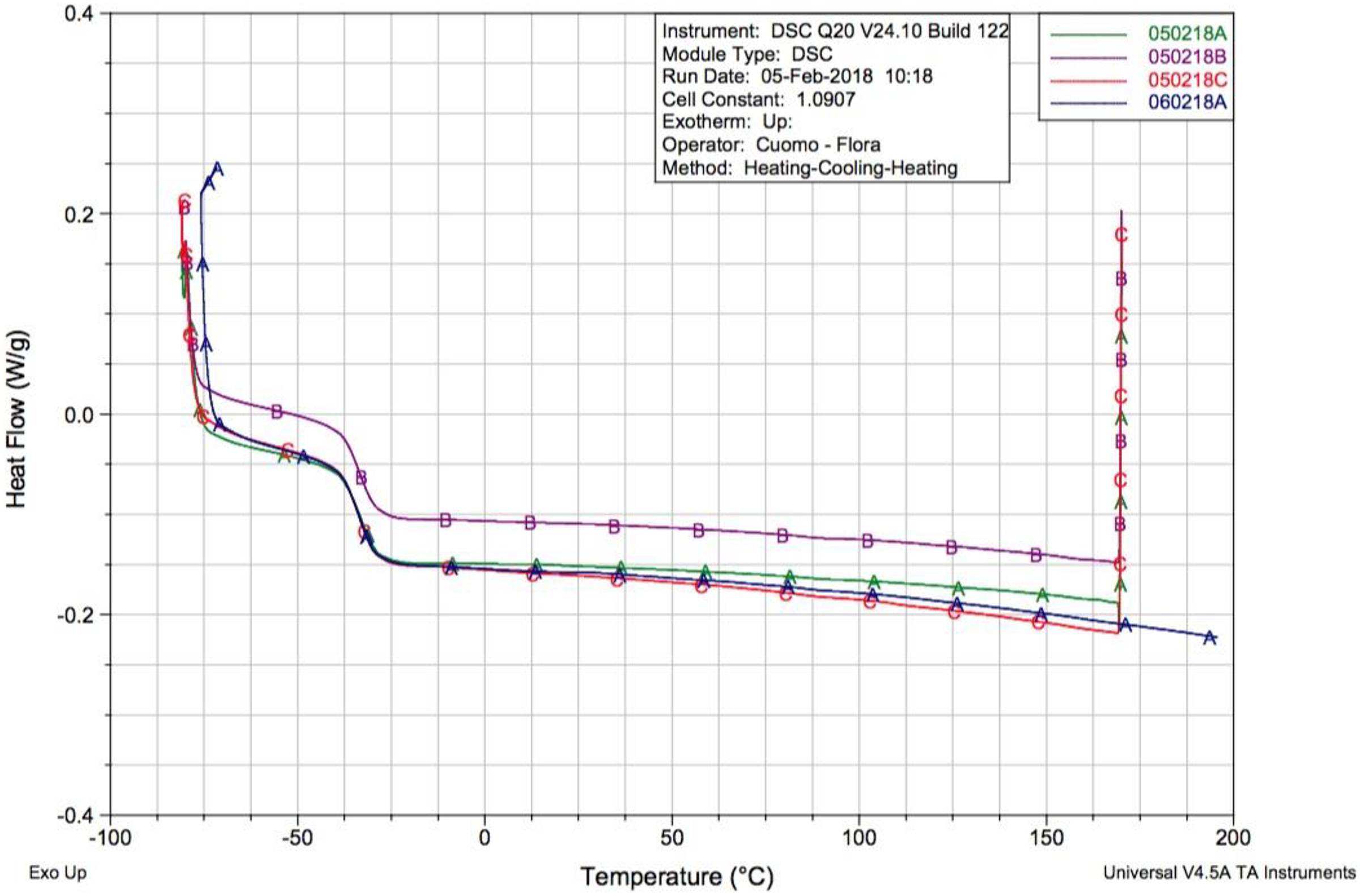
Temperature vs heat flow curves obtained for the different TPU samples.
In addition, no melting process (absence of endothermic peak) is highlighted, even in the last run (060218A curve in Figure 1) at 200°C. Considering that melting is a typical phenomenon of the crystalline domains, this behaviour suggested that the TPU selected for this experimental campaign was completely amorphous and suitable for its use at a high temperature.
Dynamical mechanical analysis
To evaluate material response variation towards load frequency and temperature, a Tritec 2000 DMA (Triton Technology Ltd., Leicester, UK) was used to perform tensile/temperature and tensile/temperature/frequency scans, following the ISO 6721-11:2012 standard. Both these tests are necessary as in a complex system like a rail vehicle sudden temperature changes can affect the mechanical response of specific components, and possible defects in the primary structures can generate vibrations in a frequency range usually between 1 and 50 Hz. Indeed, it is worth noting that a damaged wheel running at 250 km h−1 with a radius of 0.5 m is able to generate an excitation at a frequency of 22 Hz that directly affects the railway car body.
During temperature scan, the specimen was subjected to an oscillating stress, varying the temperature from −60 to 180°C, with two frequencies (1–10 Hz) and a heating rate of 2°C min−1. During frequency scan, the maximum temperature was set at 100°C, the heating rate was set at 2°C min−1, and the frequency varied between 1 Hz and 80 Hz. Liquid nitrogen was used as the cooling medium during both tests.
It is important to underline that the set-up parameters were chosen considering the operative limits of railways defined by legislation (1–50 Hz in frequency and −25/+45°C as a third climatic class temperature range-EN 50125. 2008), able to verify the suitability of TPU in this application.
Figure 2 shows the characteristic trend of the storage modulus E′ and the damping tan δ varying with temperature and frequency. For very low temperatures, as molecular chains are tight and fixed, no responses are allowed to the applied stress, and there is no resonance with the sinusoidal load, due to high stiffness (glass state). As heating increases, glass transition occurs and the chains in the amorphous region start a large-scale motion, resonating with the applied load. In this phase, the storage modulus decreases by an order of magnitude and the molecular motion associated with the glass transition is time dependent. Therefore, Tg increases when heating rate increases or test frequency increases; hence, output data showed above are consistent as in the glass transition range both tan δ peak and storage modulus variation are shifted to higher temperatures as the frequency is increased from 1 to 10 Hz (Figure 2(a)) and from 1 to 80 Hz (Figure 2(b)). After glass transition, it is possible to evaluate a rubbery plateau due to the slippage of the molecular chains. When the temperature reaches the onset melting, free volume increases and the material is able to flow as the molecular chains can slide on each other. Analysing the results, it is also clear that after 150°C the material starts showing signs of degradation of mechanical properties, compromising the dynamical response of the material, which becomes frequency dependent. From the frequency scan (Figure 2(b)), it is pointed out that, at different railway operative frequencies, TPU undergoes a variation of Tg from −30°C to −20°C, but considering that this value is still way below operative conditions; this means that even in harsh winter environments TPU will show no changes in terms of damping ability and elastic properties.
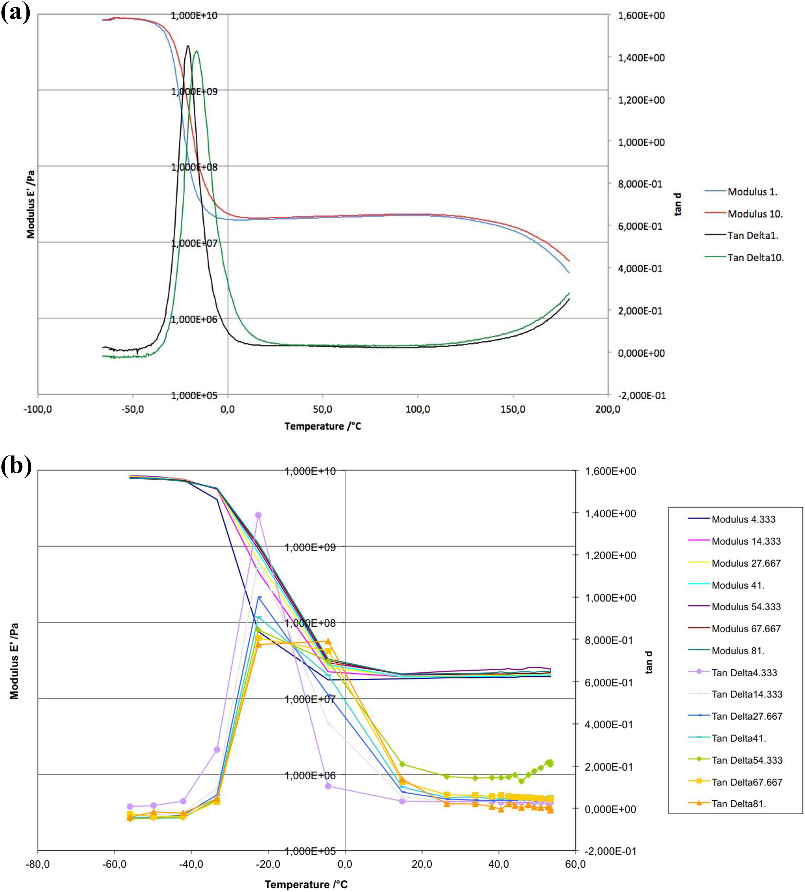
Temperature scan (a) and frequency scan (b).
Based on these results, it is possible to conclude that the use of TPU is suitable for railway applications where a broad range of different frequency excitations affect the vehicle and its structures. However, considering that the molecular structure of the TPU will start to degrade at 150°C and that the cure temperature for epoxy systems used in this study is 180°C, it would not be possible to include the TPU layer with the uncured CFRP layers in a one-step manufacturing procedure. To address this, a reduction in curing temperature, with a consequent increase in curing time, is necessary to guarantee the correct and complete cure of the CFRP laminate and the stability of the TPU polymeric system. The new cure time was obtained using a numerical linear interpolation (Figure 3) considering the starting temperature (180°C) and time (3 h) parameters and fixing the final temperature (120°C). Interpolation curve used to estimate the cure time of the TPU-coated samples.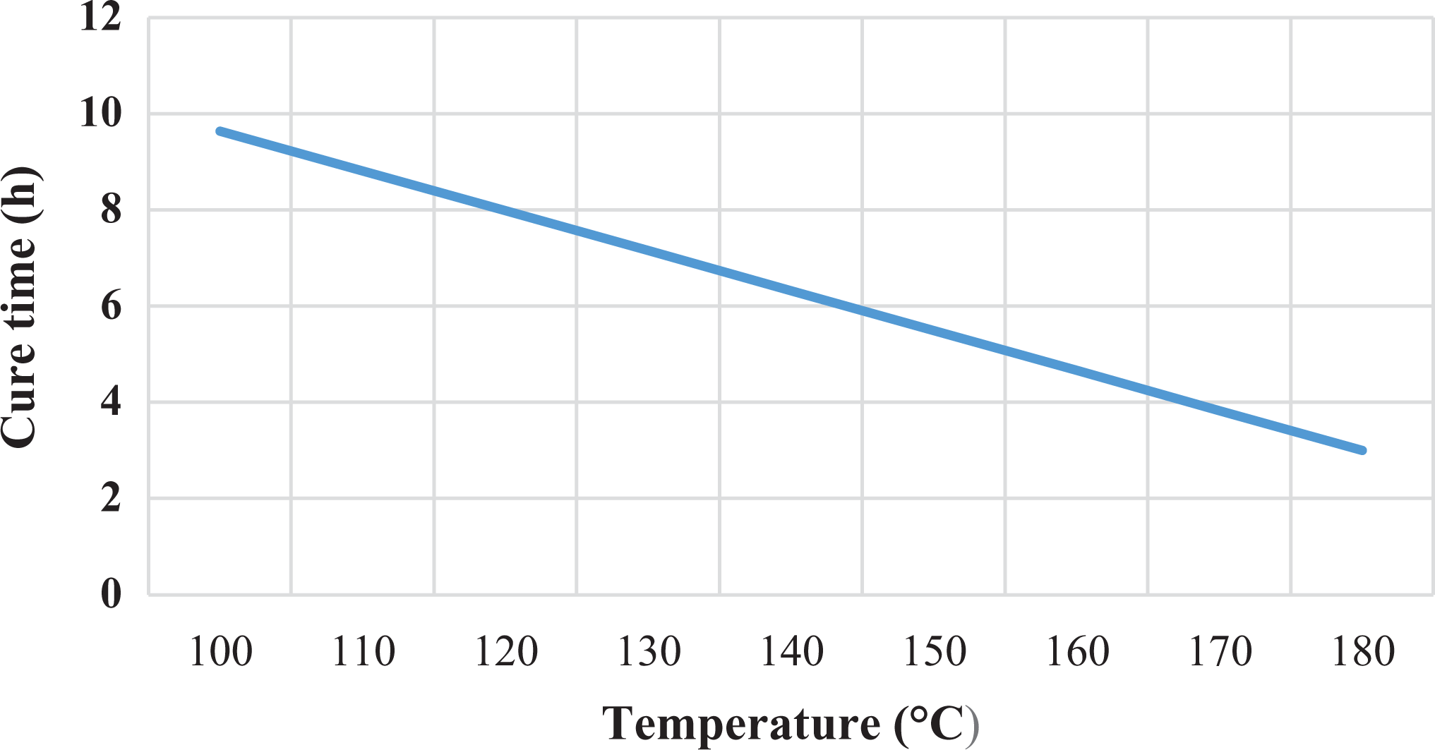
Damping test
To evaluate the energy absorption properties of TPU/CFRP samples, damping tests were carried out. The test configuration (Figure 4) was a single cantilever beam (80 × 10 mm2; w/l = 1/8), excited with an impulsive load on the free end and the oscillations were measured by a laser transducer (με optoNCDT 2300).
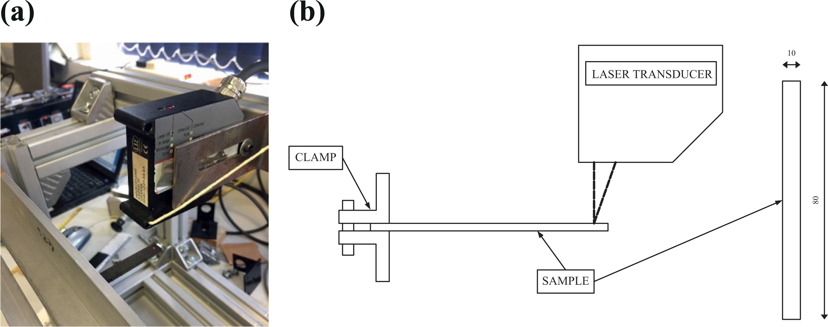
Damping test set-up (a) and scheme (b).
The capability of the TPU/CFRP samples to attenuate the impulsive load was evaluated with the logarithmic decrement
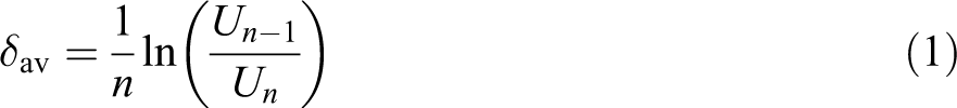
where Un is the amplitude of the oscillation.
To evaluate the optimal damping performances, different configurations of TPU/CFRP samples were tested.
The main configuration was obtained following the one-step manufacturing process, with TPU applied simultaneously with uncured CFRP (TPU autoclave cured), and the results were compared with an uncoated laminate (autoclave cured). Moreover, to analyse the effectiveness of the proposed manufacturing process, damping tests were performed also on another configuration where the TPU layer was applied on the surface of an already cured laminate using a traditional epoxy adhesive (TPU-glued).
Analysing the logarithmic decrement evaluated for the different configurations (Figure 5), the TPU in the CFRP laminate leads to an increase of damping properties in both one-step and glued manufacturing procedures, showing increases of 387% and 182%, respectively, in comparison with traditional CFRP laminates. It is important to underline, however, that the presence of the TPU layer affects the weight of the laminate; therefore, these results were rescaled evaluating the values of δ per unit weight (see Table 1), leading to a variation of +283% and +135% for the two configurations.
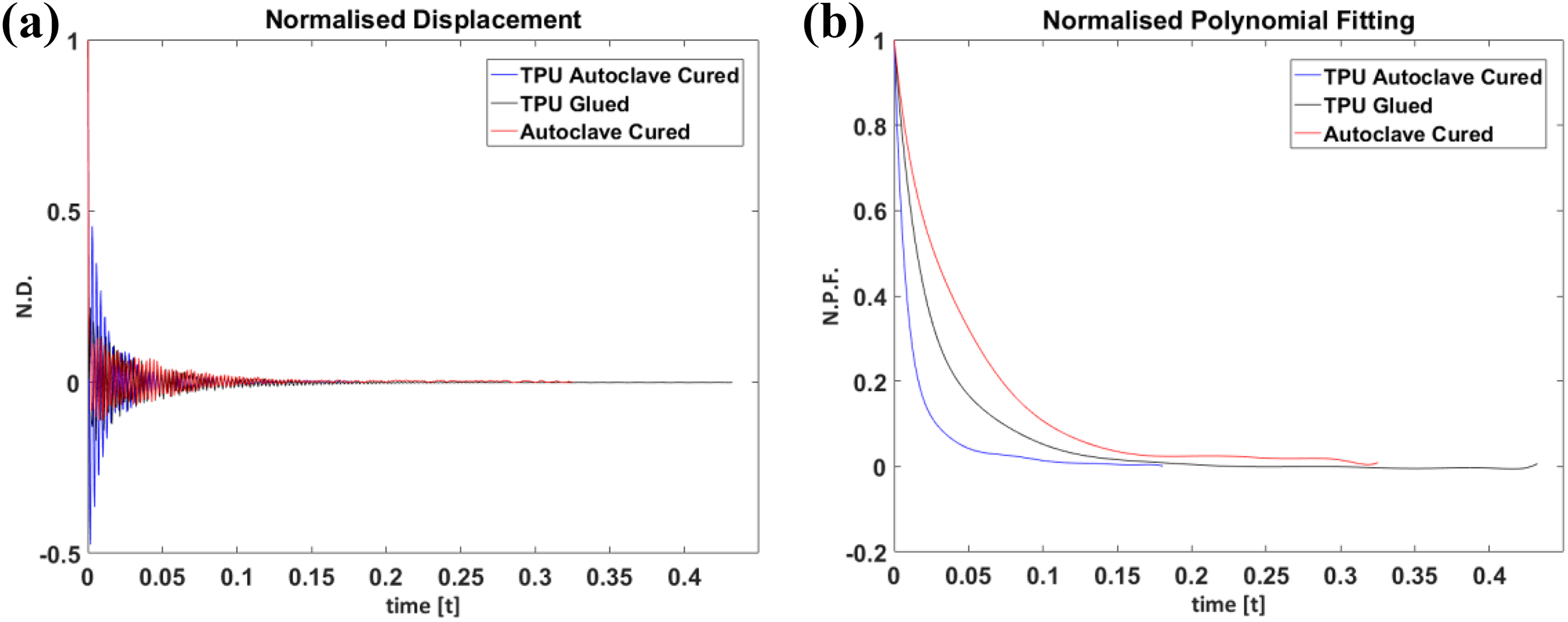
Damping test results: displacement (a) and damping (b) curves.
Logarithmic decrement (δav) and weight variations for TPU autoclave cured and TPU-glued configurations compared with autoclave cured (control).
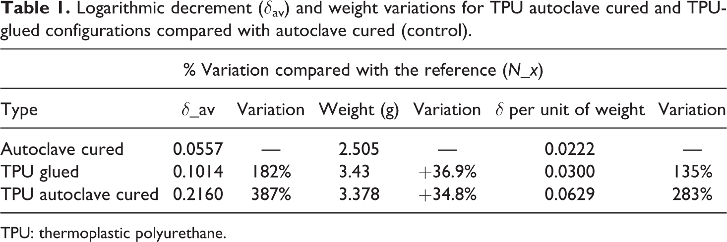
TPU: thermoplastic polyurethane.
In conclusion, considering the significant increment in damping properties for the one-step manufacturing procedure, this configuration was selected for the impact test sample manufacturing.
Samples manufacturing
The material used to fabricate the CFRP samples was a carbon fibre prepreg (CYCOM 977-2 thermoset epoxy system). A cross-ply staking sequence of 11 plies ([0/90/0/90/0/
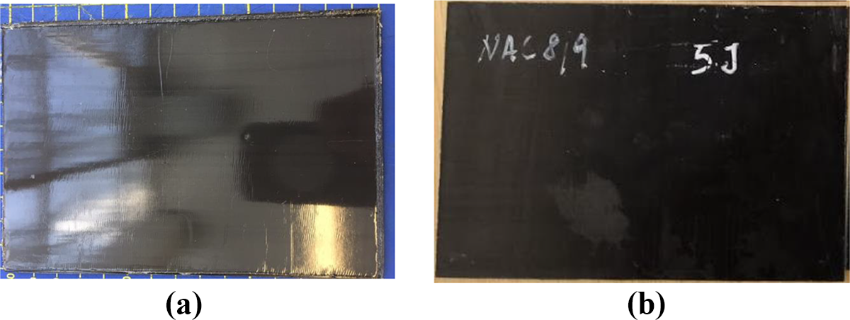
Standard impact plates used during experimental campaign: (a) TPU-coated CFRP and (b) traditional CFRP.
The average thickness values of the laminates were 2.00 mm (CFRP) and 2.8 mm (TPU/CFRP). A sketch of the sample layup is reported in Figure 7. Sketch of TPU-coated CFRP plates used during impact campaign.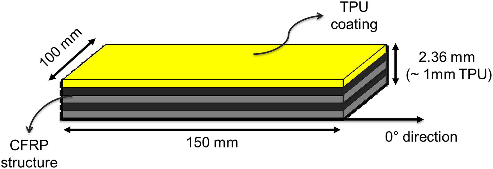
Low-velocity impact test
Experimental set-up – LVI tests
Impact tests were carried out on TPU/CFRP samples and compared with those of traditional laminates to investigate the effects of the TPU layer on the impact properties of the composite structure. Three different energy levels (2, 3 and 5 J) were used to simulate the minimum conditions to generate a flying ballast BVID in a CFRP structure as specified by the European Regulatory Framework. 27 The samples were placed into the impact machine (2.66 kg shuttle weight) using a dedicated clamping support to apply the appropriate boundary conditions to avoid undesired vibrations.
Impact data were collected using a Kistler Accelerometer, and raw signals (time–volt) were converted into force–displacement curves following BS EN ISO6603-1:2000 and BS EN ISO6603-2:2001 standards. The impactor rig scheme and apparatus are illustrated in Figure 8. All the samples were impacted following the same procedure with TPU samples being impacted with the polymer layer facing the impactor tip.
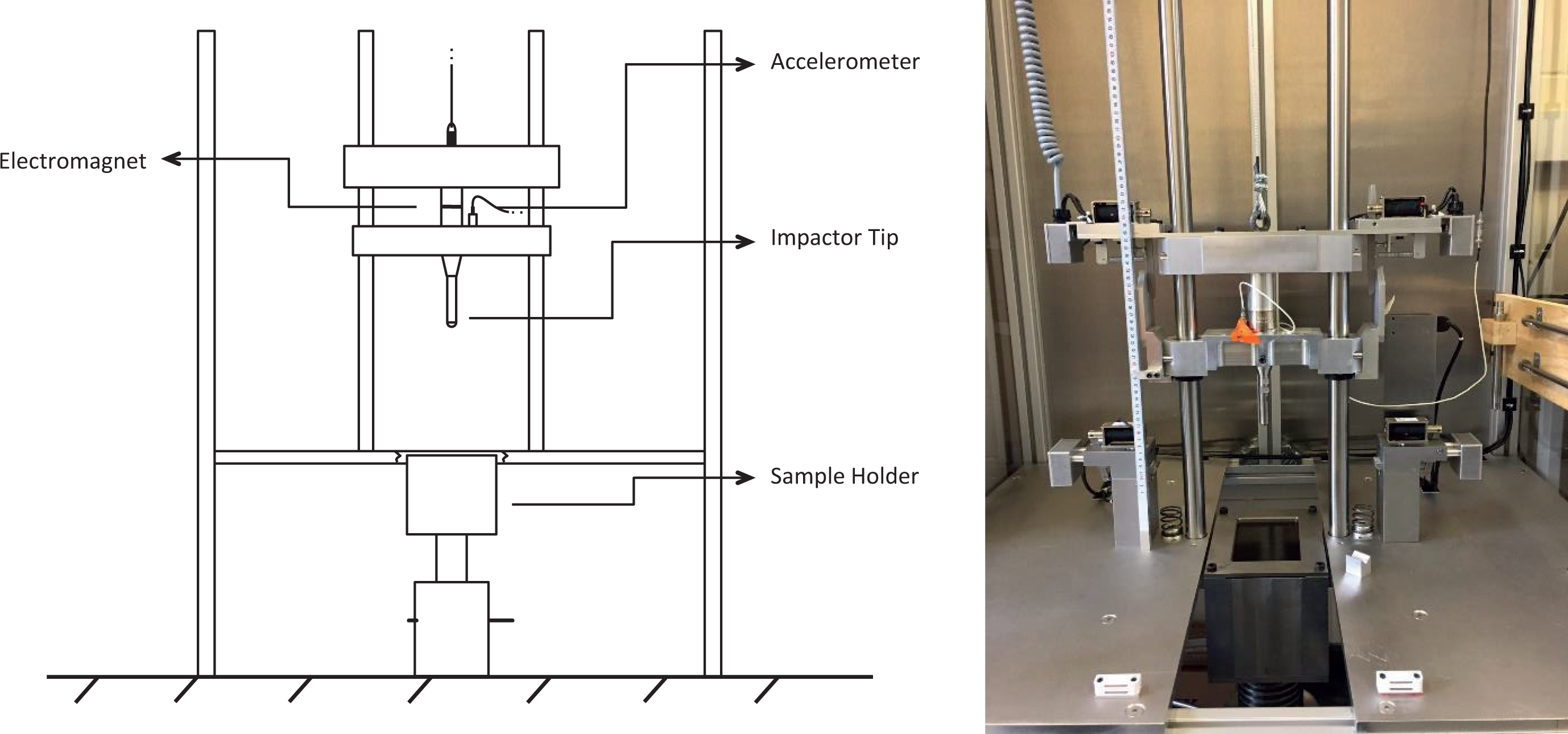
Impactor rig scheme and detail.
Experimental set-up – Phased-array scan and CT scan
The planar extension (2-D) of the internal damage was investigated using a 5-MHz phased-array transducer at 128 channels (National Instruments, Austin, USA). The beam length of each transducer corresponds to 0.58 mm in the real scale of the sample, and the images were collected with a fixed width size of 225 pixels. A digital real-scale conversion was, then, possible through direct correlation between the full length of 128 transducers (real dimension) and the relative pixels collected (digital). Images displayed the in-plane amplitude variation in a 16-bit colour-map scale from which damaged areas can be identified. The colour scale used was between 0 and 40 V where the colour red was the maximum value and the colour white the minimum.
Volumetric (3-D) images of internal damaged areas were collected using a CT scan (Nikon XT H 225, Tokyo, Japan) to confirm the results obtained with the phased array and to further analyse the impact damage typology in three dimensions. Images were collected for the entire volume of the samples and then elaborated to show the fit view of the damaged areas.
Experimental set-up – Numerical model
The testing required for the validation of a specific design in terms of safety and reliability is both expensive and time-consuming due to the entity and complexity of the process and also due to the wide range of design parameters that need to be taken into account during the development of new material solutions to manufacture primary structural components.
FE modelling is one of the most powerful tools used by modern industry to reduce the number of experimental tests that are required to validate a certain design, leading to a consequent reduction in costs and process time. Indeed, after its validation, the use of numerical model allows to optimize critical design parameters (weight, size and geometry) that advanced sector demand for the application of TPU/CFRP. Based on this premise and on the necessity to develop an accurate design and an optimization tool for a future use of TPU/CFRP laminates in real commercial parts, a 3D explicit FE model was implemented using LS-DYNA. The computational FE mesh is reported in Figure 9 where in the side view it is possible to see the presence of TPU (top layer) as coating for the CFRP laminate.
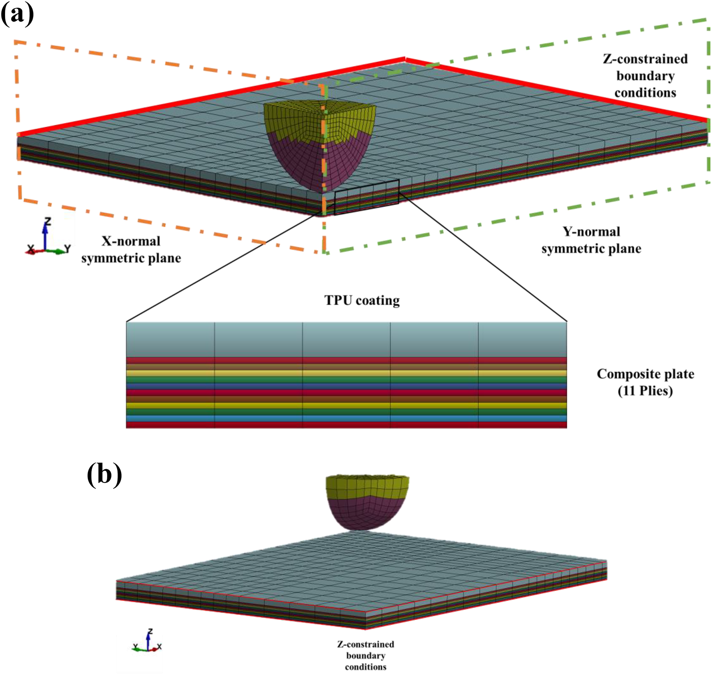
FE mesh used in the simulated LVI: (a) front-isometric and lateral view with detail of the TPU coating and CFRP plate where symmetric planes and boundary conditions are reported and (b) back-isometric view of the boundary conditions of the plate.
The impactor body was simulated as a hemispherical body of 20 mm diameter, a mass of 2.66 kg and 3-D brick elements using an ELASTIC isotropic material card (E = 210 GPa and ν = 0.3). The material was assumed elastic (no plastic deformation) as impact velocity is very low (1.93 m s−1 for 5 J case), and no plastic deformation was observed on the impacting tip during the experimental case. Parameters used during the analyses are reported in Table 2.
MAT_261 orthotropic material card parameters.
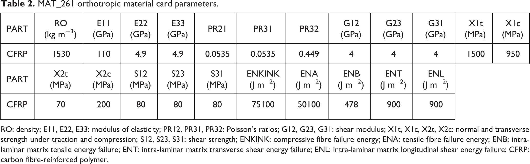
RO: density; E11, E22, E33: modulus of elasticity; PR12, PR31, PR32: Poisson’s ratios; G12, G23, G31: shear modulus; X1t, X1c, X2t, X2c: normal and transverse strength under traction and compression; S12, S23, S31: shear strength; ENKINK: compressive fibre failure energy; ENA: tensile fibre failure energy; ENB: intra-laminar matrix tensile energy failure; ENT: intra-laminar matrix transverse shear energy failure; ENL: intra-laminar matrix longitudinal shear energy failure; CFRP: carbon fibre-reinforced polymer.
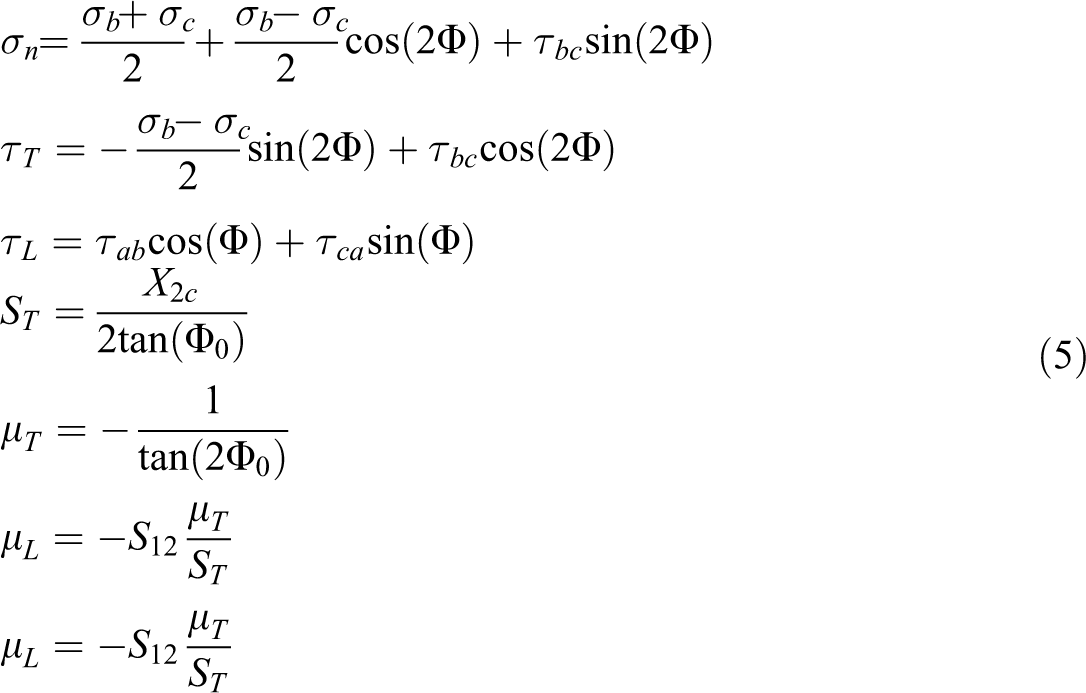
A constant stress element formulation was used to model the 3-D brick elements with an average in-plane size of 2.5 mm. Each ply was modelled using a single 0.18-mm-thick element layer. The material characteristics of the composite plate (150 × 100 × 3 mm3 in size) were defined using a MAT_261 (LAMINATED_FRACTURE_DAIMLER_PINHO) orthotropic material implementing a progressive damage model considering non-linear in-plane shear behaviour. 28 The definition of angles and stresses in fracture plane is reported in Figure 10.
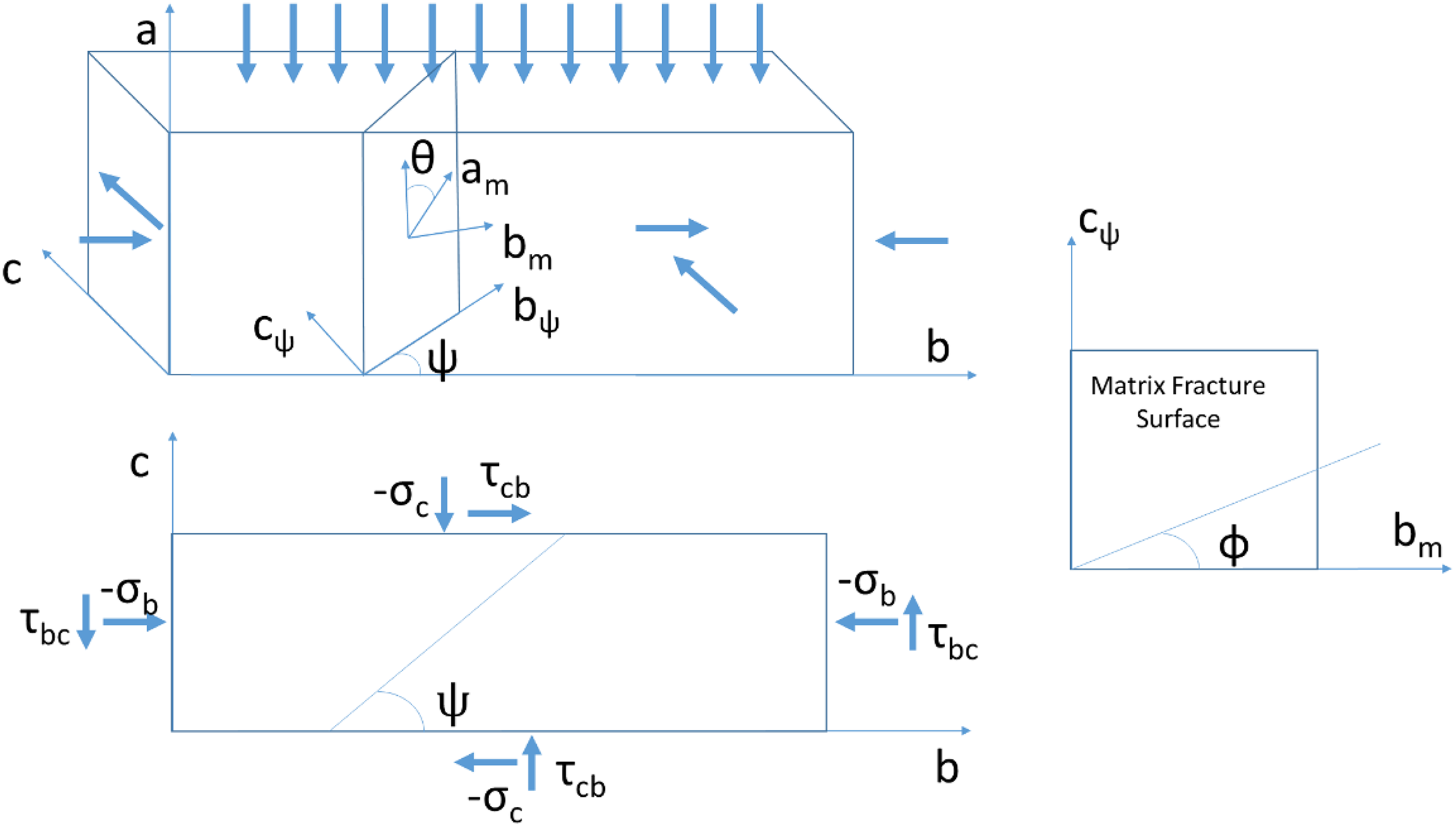
In fracture plane stresses and angles definition. 29
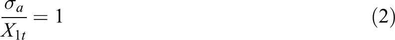
The damage initiation for longitudinal and intra-laminar failure was calculated using the stress state for each time step and the relative material strength parameters. Failure criteria are defined as follows:
Longitudinal (fibre) tension:
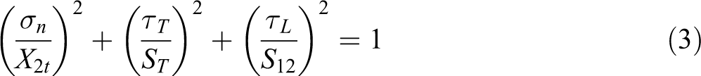
Longitudinal (matrix) failure: transverse tension (if
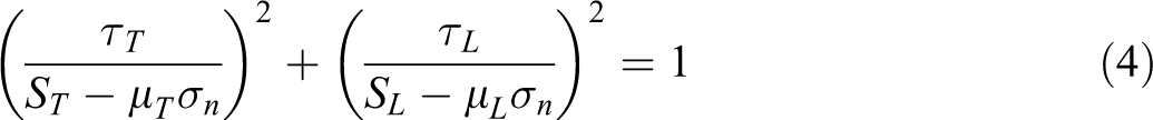
Longitudinal (matrix) failure: transverse compression/shear (if
With
considering
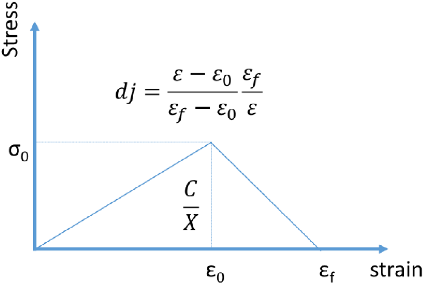
Damage evolution law for MAT_261. 29
When the stress state is within the criteria values, the material behaves as an elastic orthotropic. When, instead, one of the criteria is met, the stress is reduced by a coefficient of (1 − di) where di is one of the damage functions of the different failure modes, showing a fracture-based linear damage evolution with fracture toughness (one for each failure criterion) as a critical value (Γ). Each damage function is normalized for the element characteristic length L (see Figure 11) to have consistency between different element sizes. Element erosion was, then, evaluated for each element that satisfies one of these fracture criteria. All the equations on damage initiation and fracture criteria were reported in the MAT_261 card section of the material manual.
29
To predict the delamination component during the dynamic event and take into account the inter-laminar properties of laminated material, a TIEBREAK_CONTACT (OPTION 6) was implemented between each layer of the hybrid structure. This particular contact
30
couples together the nodes of two adjacent plies until failure initiation, defined by inter-laminar interface toughness GIC (230 J m−2) and GIIC (650 J m−2) and the relative normal (
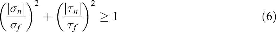
where
Afterward, the damage was scaled in function of the inter-laminar distance until complete interface separation that occurs when the distance between the plies reaches its critical value (0.1 mm).
Then, the contact is converted into a traditional PENALTY_BASED contact. The TPU-coated material was simulated using an isotropic VISCOELASTIC material card, 31,32 and all the used elastic parameters were defined considering the results obtained from DMA tests and data fitting with experimental results. The viscoelastic material properties are defined by the equation (7):

where G0 represents the short-time shear modulus (∼6.4 GPa),
Results and discussion
Output data obtained from the impact campaign are reported in Figure 12 in which force–time and force–displacement curves and their comparison are illustrated.
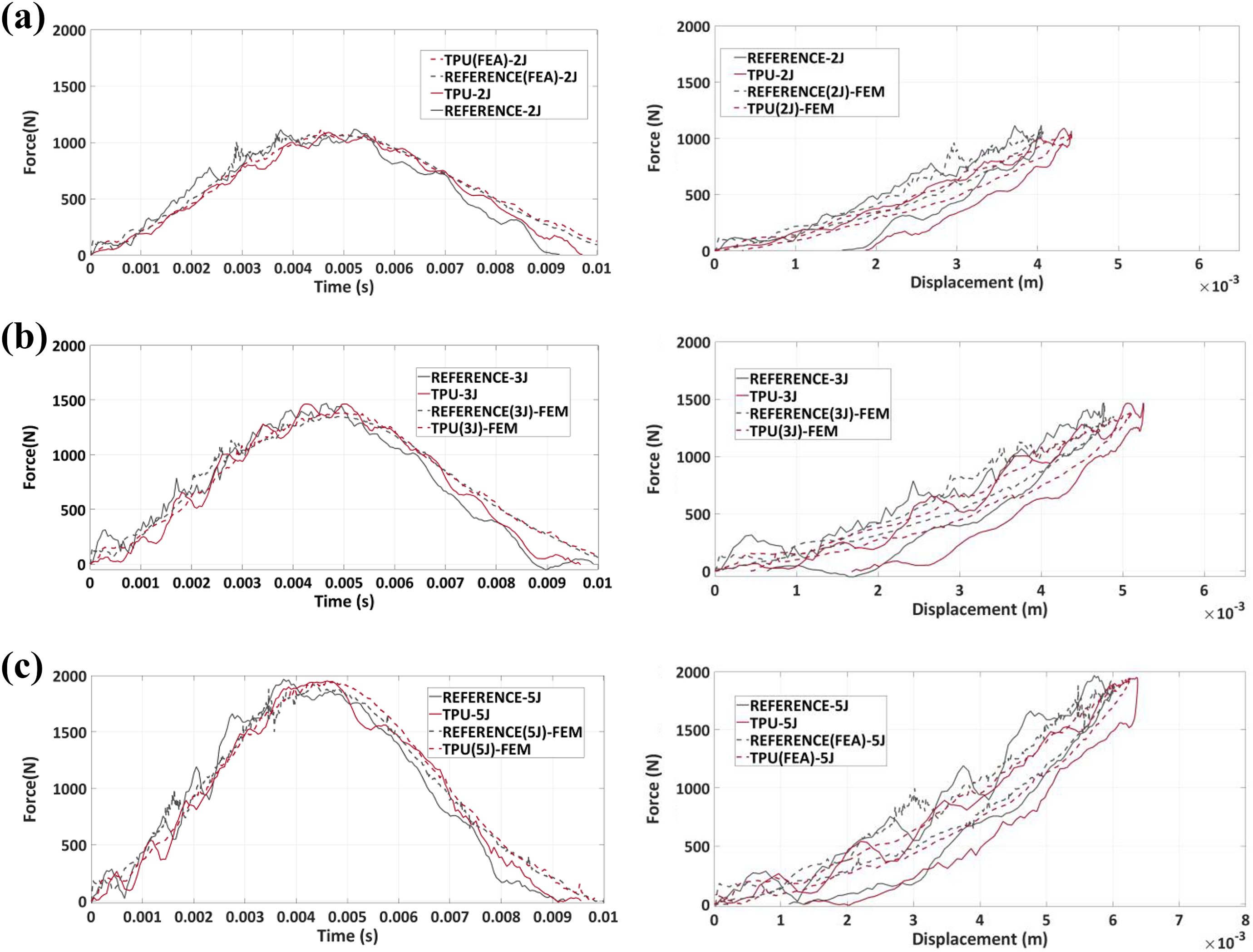
Impact results curves obtained from impact tests on control and TPU samples for different levels of energy: (a) 2 J, (b) 3 J and (c) 5 J). Force–time and force–displacement curves are reported.
The extent of the internal damage was evaluated using phased-array scans (Figure 13) from which a statistical analysis was carried out to demonstrate the consistency of damage extension results.
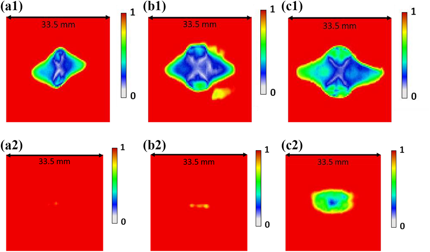
Phased-array scans from the impacted samples: (a1, b1, c1) control samples impacted at 2J, 3J and 5J; a2, b2, c2) TPU-coated samples impacted at 2, 3 and 5J. Images are collected from the external surface, far from the impacted one. The colour scale represents the normalized amplitude.
Similarly, to understand the typology and topology of the damage inside the laminate’s structure and to assist phased-array results, CT scan images were examined (Figure 14).
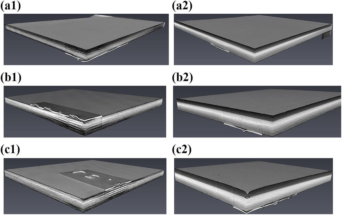
CT scan damage detection technique from the impacted samples: (a1, b1, c1) control samples impacted at 2J, 3J and 5J; a2, b2, c2) TPU-coated samples impacted at 2, 3 and 5 J.
Statistical data with mean values and standard deviations for each energy level and configuration are reported and compared in Table 3 and Figure 15.
Statistical data from impact campaign.
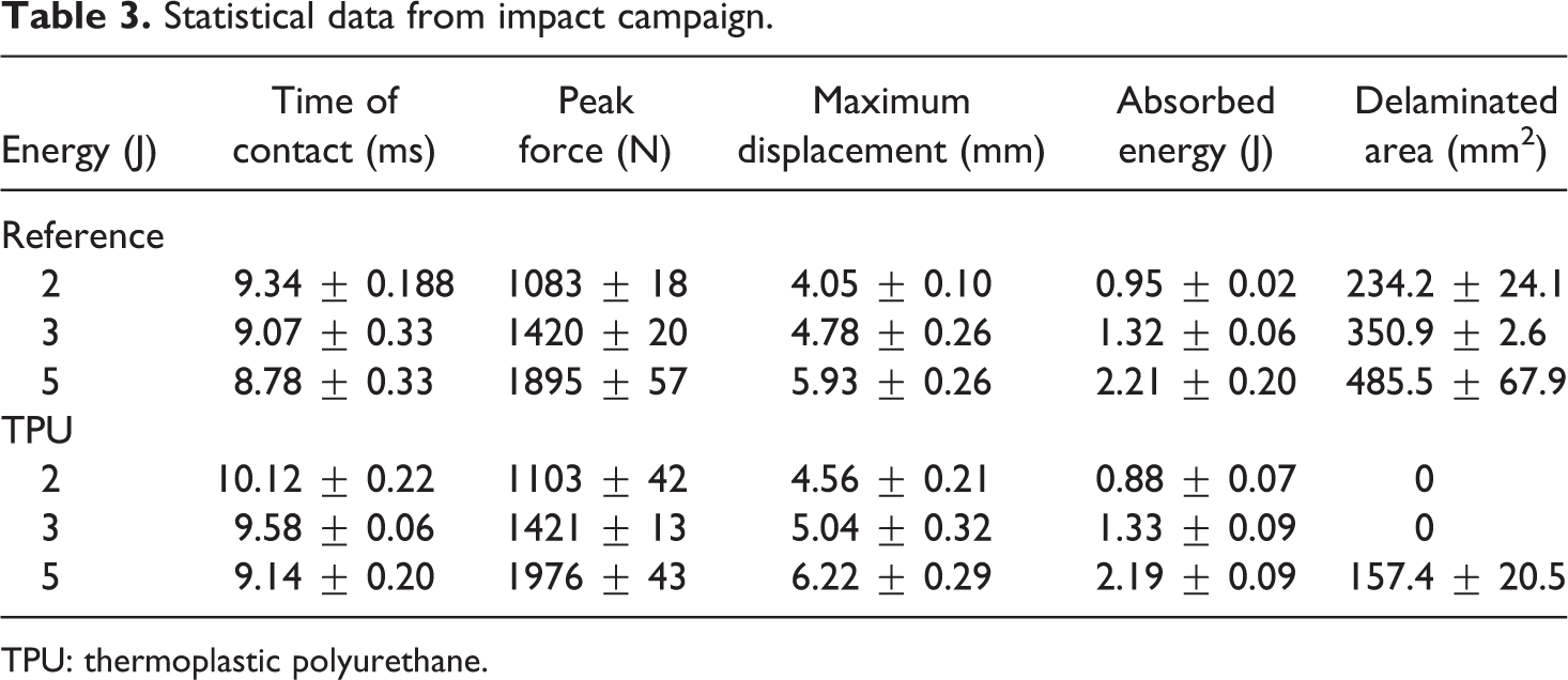
TPU: thermoplastic polyurethane.
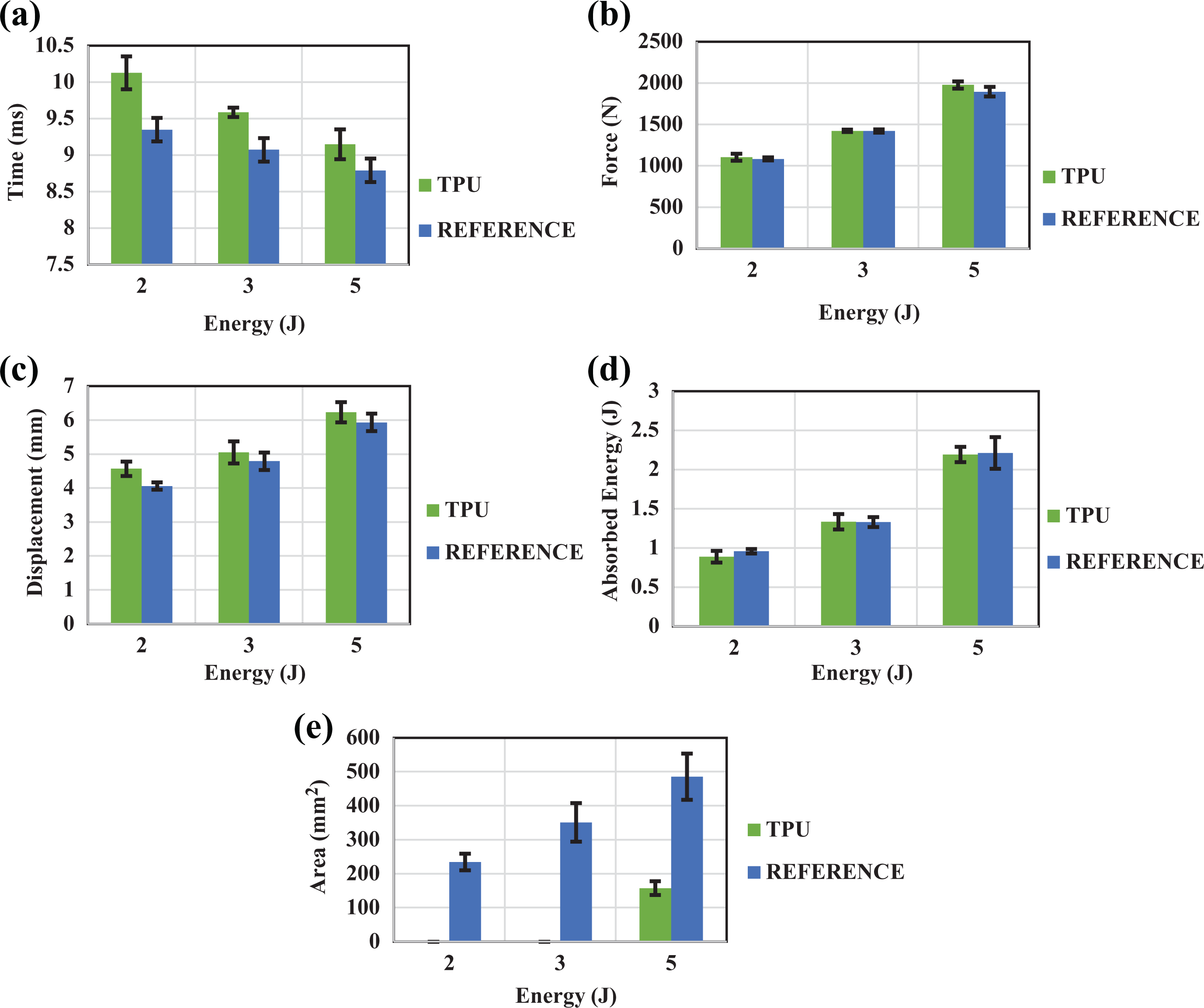
Statistical data charts on impacted data for 2, 3 and 5 J impacts. Mean values for each impact parameter and respective standard deviation are reported in the column chart for control and TPU sets: (a) time of contact, (b) maximum contact force, (c) maximum displacement, (d) absorbed energy and (e) damaged area extension measured from C-scan images. TPU samples have no structural damage within the CFRP portion, and the reported values correspond to the TPU–CFRP interface separation.
As predicted in literature, 33 the impact behaviour of both configurations changes according to the impact energy. In particular, for TPU/CFRP samples, maximum displacement and time of contact (in comparison with uncoated samples) increase by +8.34% and +12.58% for 2 J, +5.66% and +5.44% for 3 J and +4.10% and 5.01% for 5 J (see Figure 15(c) and(a)), reporting that the increase in displacement between TPU-coated and control samples tends to decrease for higher energetic impacts due to the viscoelastic effect of TPU layer. 34 The presence of TPU has reduced the influence on force peak values (Figure 15(b)) with minimal variations in terms of impact response for the different energy levels (see Figure 12). The percentage variation in comparison with the reference is +1.85% for 2 J, +0.08% for 3 J and +4.26% for 5 J.
Another important results are shown in Figure 15(d), where a similar absorbed energy is reported for both tested configurations (see Figure 15(e)), suggesting that the presence of the TPU coating enables different energy absorption mechanisms. As a consequence, it is important to correlate the information obtained with the LVI tests with the internal integrity status of post-impact samples. Phased-array images of control samples (Figure 13) indicate widespread damaged areas with damage extension increasing with impact energy. In contrast, TPU/CFRP samples show no signs of defects within the laminate, with the exception of the samples impacted at 5 J, where a small damage can be seen in correspondence with the indentation point area. The variations in terms of damaged areas between TPU-coated and traditional CFRP samples are −100% for 2 J (undamaged), −100% for 3 J (undamaged) and −67.5% for 5 J. CT scan images of the control samples (Figure 14) show wide damaged areas that can be clearly identified as a typical reversed pine-tree propagation shape characteristic of matrix failure, whose severity and extension increase with the increase of impact energy, confirming the results shown for phased-array images. On the contrary, CT scan images of TPU-coated samples show no signs of damage in the entire body of laminate for all impact energies, in apparent contrast with what was observed with the phased-array scans for the 5 J samples (Figure 13(c2)). The difference between the outputs of the two tests was found to be due to the presence of a small area within the TPU layer showing signs of interface separation between TPU and CFRP that was indistinguishable from a structural damage from the phased-array images. Consequently, TPU-coated samples impacted at 5 J do not present any sign of structural damage in the CFRP portion as the damaged area detected in the phased-array images corresponds to the TPU interface separation.
By comparing the experimental results with the output of the numerical model, it is possible to observe that the model is able to predict the damage-suppression ability of the TPU coating, as reported in the comparison graphs in Figure 10. In particular, the numerical curves for traditional CFRP laminate show load drops similar to the ones observed experimentally (around 3 ms for 2 and 3 J and around 3 and 4.5 ms for 5 J), while numerical simulation of the TPU-coated samples shows no damage, also confirming the experimental results. Errors of +2% and −0.7% for 2 J for uncoated laminates and +8% and +3% for the TPU/CFRP are found in terms of maximum contact force and maximum displacement between experimental and numerical results, showing a good accuracy in predicting the impact output data for both traditional and TPU/CFRP. Similarly, considering 3 J impacts, the overall maximum contact force and maximum displacement are around the same values detected for the 2 J impact case with +5% and −0.2%, respectively, for the reference samples and +2% and −0.1% for the TPU/CFRP ones. Also 5 J impact case shows differences in terms of maximum force and maximum displacement similar to the two previous cases, reporting −1% and −4% for the reference configuration and +1% and +0.3% for the hybrid case. Thus, the results show a good correlation between experimental data and the numerical model for values of stiffness, maximum displacement and maximum contact force, even if the force−displacement descendent curve portion presents a slight mismatch. These small variations can be the result of the formation of defects during the cure process that affects the numerical data for mechanical properties and the elastic energy release during the unloading phase of the impact event.
In order to explain the different behaviour of the TPU-coated CFRP, it is important to analyse the different mechanisms utilized to store or absorb energy by estimating the energy transfer from the impacting mass to the sample during the impact event. 30 –32 In general, for LVIs where no visible damage is reported, a total kinetic energy transfer (Etotal) takes place from the impactor’s tip to the sample in correspondence with the contact point, and the energy is distributed into the laminate in different forms. One such form is the elastic energy contribution (Eelastic), which represents the ability of the material to store energy via non-permanent geometrical deformation. This energy is transferred back to the penetrator after maximum displacement of the plate is reached. Another form is the energy absorbed (Eabsorbed) by the impacted object. 35 –37 Therefore, for the energy conservation balance, it is possible to write:

Eabsorbed can be further divided into three different contributions: Edamage, representing the energy required to generate damage inside the structure (e.g. fibre failure, matrix failure and delamination), Eviscous that is the energy absorbed via viscoelastic mechanisms 38 and Edissipation that encompasses all other dissipation modes including heat, inelastic behaviour of components and all non-linear behaviours. Thus, the equation can be written as follows:

Considering the layered nature of CFRP,
39
in traditional laminates damage generation is the main cause of energy dissipation, due to the creation of new surfaces between two adjacent plies at different fibre orientations (i.e. delamination). For this reason, a notable amount of energy is absorbed in a laminated system, and the
In contrast, using a TPU layer, an additional damage suppression ability is introduced into the CFRP system due to the high strain at failure and damping ability of the polymer. 40
Indeed, as TPU is characterized by a lower stiffness and higher strain at failure, it is able to increase the global elastic energy threshold that the material can tolerate before damage is generated. As a consequence, a lower amount of energy is found into the Edamage term, and consequently, less impact energy is dissipated via the creations of defects.
In addition, the hybrid system is able to absorb a larger amount of impact energy via viscoelastic losses of TPU layer. This allows to take into account more energy into the Eviscous term and lower the weight of the Edamage term, meaning smaller damaged areas generated into the sample.
Therefore, it is possible to conclude that the coupled effects of increased elastic properties and improved damping given by the TPU layer allow the absorption of all the impact energy via these two components, generating no damaged areas within the laminate’s body.
Compression-after-impact
To confirm the results obtained with the LVIs and the NDT analyses, post-impact samples were subjected to a CAI campaign to analyse the residual compressive strength and prove the damage suppression ability of the TPU layer.
Experimental set-up
CAI tests were performed using an Instron Universal Machine 5585 in a compressive mode following the ISO 19352:2009 standard. A rig of 150 × 100 mm2 was used to constrain the sample and guarantee a pure compressive load applied on the sample section. A schematization of the used rig is reported in Figure 16.
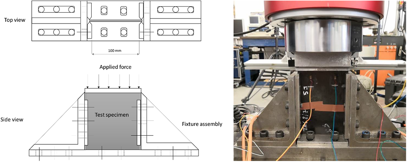
Schematization of CAI rig assembly.
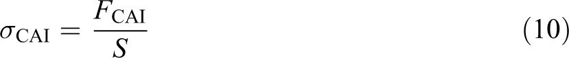
Samples were stabilized at the edges by the fixture without constraining the in-plane transverse deformation. For all tested samples, four strain gauges were used in order to record the applied strain and ensure the parallelism to the lateral supports, flatness and exact positioning of the sample in the rig. During the tests, the force was recorded and elaborated using equation (10) to evaluate the residual compressive strength of each sample. Considering this equation,
Results and discussion
CAI results are reported in Figure 17, where output values correspond to the residual compressive strength evaluated considering 100% as an undamaged CFRP structure.
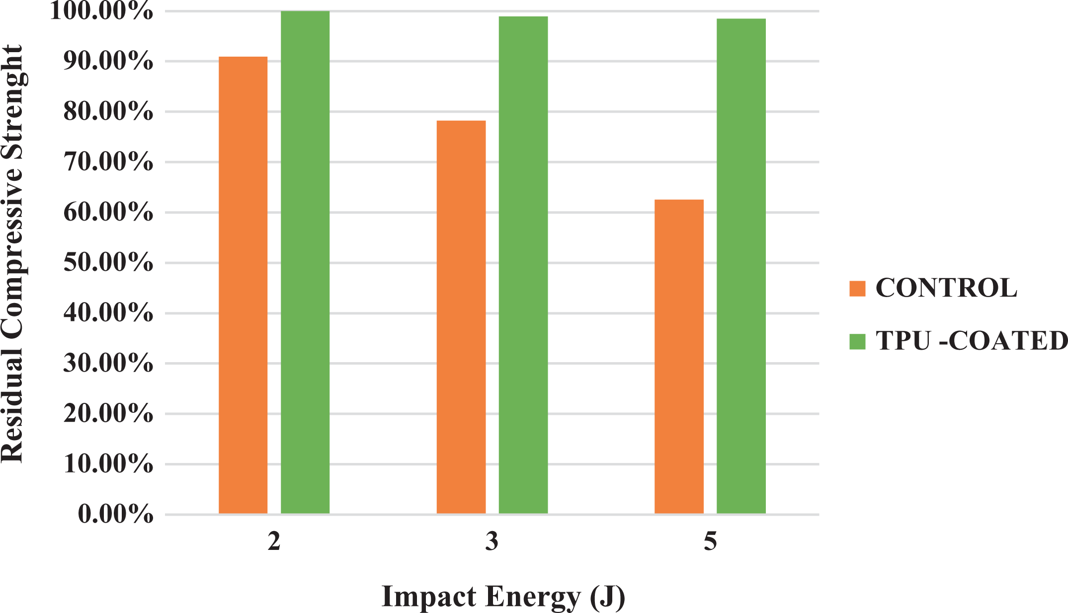
CAI results obtained from the test of samples impacted at 2, 3 and 5 J.
As TPU-coated samples showed an asymmetrical geometry (TPU layer on one surface) during CAI failure, a small bending component was observed affecting the recorded compressive strength. This led to an oscillation in the residual compression strength for TPU-coated samples at different impact energies. To overcome this issue, TPU layer was carefully removed from the samples prior to the tests ensuring that no damage was created within the laminate during the operation using C-scan analyses.
It is possible to see from the results that traditional CFRP samples show a significant reduction in terms of residual compressive strength that becomes more dramatic as the impact energy increases (90.96% for 2 J, 78.19% for 3 J and 62.54% for 5J). TPU samples instead show higher in-plane residual compressive properties due to the absence of damaged areas in the laminate body, confirming what was observed from the previous tests.
Conclusions
The principal aim of this work was to investigate the improvement of the impact properties derived from the application of a layer of TPU blend as a coating layer on the impact surface of CFRP laminates. This superficial layer was applied on the samples’ surface during the lamination sequence prior to the curing process, using a one-step manufacturing process aimed at reducing costs and time in comparison with conventional coating procedures. An extensive study was carried out using DSC and DMA to determine the optimal cure parameters for autoclave curing in function of the thermal properties of the polymer and the operative conditions in railways. Results showed TPU glass transaction at −33°C and mechanical properties degradation at 150°C in the range of frequency between 1 and 80 Hz that overestimates the real operative conditions of the material in railways. Damping tests were performed showing an increment of 113% and 387% in logarithm decrement for the TPU/CFRP manufactured with the one-step process in comparison with TPU glued on CFRP and traditional uncoated CFRP. An impact campaign was then carried out, and the results indicated that traditional CFRP laminates show large internal damaged areas that become larger for higher impacts, while no sign of damage was found in the TPU-coated laminates. This is attributed to the presence of TPU capable of storing elastic energy and dissipate higher amount of impact energy via viscoelastic losses, with no measurable damage (i.e. cracks and delamination). This result was confirmed by analysing the residual compressive strength of traditional and TPU-coated laminates, showing no variation in residual mechanical properties for TPU-coated CFRP as no damage was generated during an LVI event. In contrast, traditional CFRP laminates showed a significant variation in residual strength (90% for 2 J, 78% for 3 J and 62% for 5 J) in function of impact energy due to delamination. A numerical model was then developed to support the optimization process of the TPU-coated CFRP for designing future advanced structural components where this material will be used. A good correlation between experimental and numerical results was found with a maximum error of 8% between experimental and numerical data, demonstrating that the developed numerical model is an excellent tool to predict the mechanical response of TPU/CFRP laminates.
In conclusion, the introduction of TPU as an additional reinforcement layer for damage suppression makes hybrid TPU/CFRP laminates a promising candidate for the development of a new generation of lightweight railway vehicles, able to withstand flying ballast-like events without the generation of BVIDs, enhancing safety and reliability of the entire rolling stock.
Footnotes
Funding
The author(s) disclosed receipt of the following financial support for the research, authorship, and/or publication of this article: This paper has been funded by the EXTREME project of the European Union’s Horizon 2020 research and innovation programme under Grant Agreement No. 636549.