
Abstract
In this study, polysulfone (PSf) nanocomposite membranes (NCM) have been fabricated by reinforcement with silica-modified zeolite (SiO2-MZ) and polyimide (PI)-SiO2-MZ as inorganic nanocomposite (NC) fillers. To evaluate the improvement in structural, mechanical, and thermal properties of PSf matrix, these nanofillers were incorporated systematically from 1 wt% to 10 wt%. Morphological analysis using transmission electron microscopy and scanning electron microscopy shows better compatibility between PI-SiO2-MZ as the inorganic nanofiller and polymer matrix as compared to SiO2-MZ filler. Physical characteristics of NCMs were studied by Fourier transform infrared spectroscopy and X-ray diffraction analysis. The appropriate ratio of PI-SiO2-MZ as nanofiller in PSf matrix was found through structural analysis. Thermal analysis using differential scanning calorimetry revealed an increase in glass transition temperature (Tg) with increasing filler concentration. Young’s modulus of PSf/SiO2-MZ NCM (10 wt%) was found to be 1109 MPa, which was improved to 1438 MPa for PSf/PI-SiO2-MZ (10 wt%) NCM. Membrane properties like swelling degree and porosity were also calculated. The degree of swelling of NCMs decreases with decrease in the hydrophilicity of the solvent. Antibacterial properties of NCMs were explored against four bacterial strains namely Klebsella pneumonia, Salmonella typhi, Bacillus subtilis, and Staphylococcus aureus. Good antibacterial activities were obtained for PSf membranes reinforced with PSf/PI-SiO2-MZ NC filler.
Keywords
Introduction
Hybrid functional nanomaterials containing both organic and inorganic constituents have gained significant interest in recent years. 1,2 These organic and inorganic components are mixed intimately for fabrication of hybrid materials. Specifically, polymer nanocomposites are the combination of polymer matrix with nanoscale or hybrid inorganic materials. The properties of filler–polymer composite depend on the interaction and dispersion of nanofillers in the polymer matrix. 3,4 The nanocomposite membrane (NCM) is a combination of predominant properties of inorganic membranes and processability of organic polymer membranes. 5,6 Reinforcement of filler in the polymer matrix results in interactive effects.
High-performance polymer NCMs can be synthesized by reinforcement of inorganic filler into polymer matrix with improved mechanical, thermal, and structural properties. 7 To attain better results, the mixture of fillers can be employed in small quantities due to their small size and high surface area. 8 Properties depend on the dispersion of filler in the membrane matrix. 9 Such nanofiller-reinforced NCMs have found applications in water purification, drug delivery, gas separation, and biomedical domain.
Polysulfone (PSf) is a commonly used thermoplastic for membrane synthesis because of its toughness and stability at high temperatures. 10 It is highly rigid having good resistance to creep and hydrolysis in addition to good economical processing. On the other hand, polyimide (PI) is another well-known thermoplastic polymer, and its materials are generally lightweight and flexible with good thermochemical and mechanical properties. 11 Zeolites (Z) or aluminosilicates are attractive inorganic materials with uniform sized stable micropores orderly distributed through their surface. 12 They can act as a catalyst as well as exhibit molecular sieve properties due to its porous nature and can reject or adsorb molecules selectively depending on pore shape and size. 13,14 However, properties may vary depending on the alumina and silica (SiO2) content. Adsorption properties of composite materials can be enhanced considerably by the addition of SiO2 nanoparticles as they possess remarkable surface area. 15 Many researchers have synthesized PSf-based NCMs for different applications. For instance, Sirinupong et al. have fabricated titania–graphene oxide (TiO2-GO)-incorporated PSf membrane for osmosis. Surface roughness, hydrophilicity, and water flux were increased on the incorporation of TiO2-GO in this PSf membrane. 16 Similarly, Fan et al. synthesized polyaniline (PANI)-incorporated PSf ultrafiltration membrane. 17 Good permeability, positive surface potential, and better hydrophilicity were observed for PSf/PANI NCM as compared to a pure one. Also, Jadav and Singh have reported that SiO2-incorporated polyamide NCM shows improved thermal stability as compared to neat polyamide membrane. Moreover, the reinforcement of SiO2 nanoparticles has improved the pore number density of NCM, which enhanced the permeation ability. 18
In the current study, four types of fabricated PSf membranes named as polysulfone/silica–zeolite (PSf/SiO2-Z), PSf/SiO2-MZ, PSf/PI-SiO2-Z, and PSf/PI-SiO2-MZ NCMs were prepared. Our results suggested that these membranes have better mechanical, structural, thermal, and antibacterial properties as compared to neat PSf membrane. Multiple properties combined in a single membrane offer a wider application range.
Experimental section
Materials
PSf (average number-average molecular weight ∼ 2.2 × 10⁴ g mol−1 ), 4-aminephenyl sulfone, pyromellitic dianhydride (PMDA, 97%), and (3-aminopropyl)-trimethoxysilane (APTMS, 99%) were purchased from Sigma-Aldrich (China). Dimethylsulfoxide (DMSO, 99.5%) was purchased from Fluka (China). Ammonium hydroxide (33%) was supplied by Riedel-de Haen (China). Glacial acetic acid (99%), dimethyl acetamide (DMAc, 99.5%), 1, 1, 1-trichloroethane, zeolite A-3 granular, tetra ethyl ortho silicate (TEOS, 98.5%), and hydrochloric acid (37%) were obtained from DaeJung (China) and were used as received. PI synthesis and zeolite modification details are given in “Synthesis and fabrication” section. All the experiments were repeated thrice to ensure reliability.
Instrumentation
Fourier transform infrared (FTIR) spectrometer model Bruker Tensor II (Germany) was used to obtain FTIR spectra. Transmission electron microscopy (TEM) was done by using a Hitachi Tecnai G 20 model (Japan). The testing samples for TEM were prepared by mounting the NCMs sectioned in small pieces over a copper grid and covered with a thin amorphous carbon film with holes. Field-emission scanning electron microscopy (SEM) was recorded using a Hitachi S4800 model. Testomeric material testing machine model M500-30CT was used to record the stress–strain behavior of samples. Thermal stability was analyzed by using METTLER TOLEDO thermogravimetric analyzer (Switzerland) with 5 mg of sample in Al2O3 crucible at a heating rate of 10 K min−1 . XRD study was performed on Shimadzu XRD-6000 (Japan) using crystal monochromatic copper Kα (λ = 1.5406 Å, wide angle 2θ = 5–50°) at a scanning rate of 8° min−1 .
Synthesis and fabrication detail
In this work, all NCMs were prepared by solution casting method. 19 Nanocomposites (SiO2-Z, SiO2-MZ, PI-SiO2-Z, and PI-SiO2-MZ) were ex situ synthesized and later were added to the PSf matrix for the formation of NCMs. The details of synthesis and modification of each nanocomposite (NC) are dealt in the subsequent sections.
Synthesis of nanofillers
Synthesis of SiO2-Z NC
SiO2-Z NC was synthesized by dispersion of 1 g of zeolite into a mixture of 0.7 g Cetyl trimethylammonium bromide (CTAB), 200 g distilled water, 120 g ethanol, and 2.5 g ammonia. 20 The mixture was kept in an ultrasonic bath for 1 h. After 1 h, 11.2 g of TEOS was added dropwise to the above reaction mixture, and it was set for overnight stirring at room temperature (RT). The reaction mixture was filtered, and the obtained product was dried in an oven at 100°C.
Modification of zeolite
About 1 g of zeolite was dissolved in 50 mL of 1,1,1-trichloroethane, and the resulting mixture was kept on stirring at RT. After 1 h, APTMS was added dropwise to the mixture and was refluxed at 60°C for 3 h. The obtained residues were filtered and washed with methanol and then dried in an oven at 80°C. Terminal amino groups were provided to zeolite through a reaction between methoxy group of silane and zeolite. The detailed schematic representation for zeolite modification has been given in our previous publication. 21
Synthesis of SiO2-MZ NC
SiO2-MZ NC was synthesized by dispersion of 1 g MZ into a mixture of 0.7 g CTAB, 200 g distilled water, 120 g ethanol, and 2.5 g ammonia. The mixture was kept in an ultrasonic bath for 1 h. After 1 h, 11.2 g of TEOS was added dropwise to the above reaction mixture, and it was set for overnight stirring at RT. The reaction mixture was filtered, and the obtained product was dried in an oven at 100°C.
Synthesis of PI
PI was synthesized through polyamic acid route. Equimolar amounts (0.02 mol) of PMDA and 4-aminophenylsulfone were added in 100 mL of glacial acetic acid. The resulting mixture was refluxed at 110°C for 15–18 h in a round-bottomed flask furnished with a nitrogen inlet and magnetic stirrer. The color of the reaction mixture changed from transparent to milky white, then to yellowish, and finally to chocolate brown. The precipitates were washed with methanol and dried in a vacuum oven at 80°C. Schematic representation of PI synthesis is given elsewhere. 22
Synthesis of PI-SiO2-Z NC
In a typical synthesis procedure for fabrication of PI-SiO2-Z NC, solution 1 was prepared by dissolving 0.5 g PI in 10 mL DMSO, while solution 2 was prepared by dispersion of 1 g zeolite into a mixture of 0.7 g CTAB, 200 g distilled water, 120 g ethanol, and 2.5 g ammonia. Both solutions were stirred for 1 h. After 1 h, solution 1 was added dropwise to solution 2, and the reaction mixture was sonicated in an ultrasonic bath for 1 h. About 11.2 g of TEOS was added to the reaction mixture, and it was set for overnight stirring at RT. 23 The reaction product was dried in an oven at 100 °C.
Synthesis of PI-SiO2-MZ NC
In a typical synthesis procedure for fabrication of PI-SiO2-MZ NC, solution 1 was prepared by dissolving 0.5 g PI in 10 mL DMSO, while solution 2 was prepared by dispersion of 1 g MZ into a mixture of 0.7 g CTAB, 200 g distilled water, 120 g ethanol, and 2.5 g ammonia. Both solutions were stirred for 1 h. After 1 h, solution 1 was added dropwise to solution 2, and the reaction mixture was sonicated in an ultrasonic bath for 1 h. About 11.2 g of TEOS was added to the reaction mixture, and it was set for overnight stirring at RT. The reaction product was filtered and dried in an oven at 100°C.
Fabrication of PSf membrane with different nanofillers
Polysulfone/silica–zeolite nanocomposite membrane
For fabrication of PSf/SiO2-Z NCM, 1 g of PSf beads were added to 10 mL DMAc solvent and the reaction mixture was stirred for 2 h. After homogeneous dispersion of PSf beads in the DMAc solvent, varying concentrations of synthesized SiO2-Z NC (1, 5, and 10 wt%) were added to the casting solution. It was stirred for 2 h. After complete dissolution of SiO2-Z NC in PSf matrix, the mixture was cast on a glass petri dish and dried in the vacuum oven at 80°C. The PSf/SiO2-Z NCM was peeled off with the help of a doctor’s blade. The theoretically estimated amount of SiO2-Z NC in the PSf membrane was 1, 5, and 10 wt%, respectively.
Polysulfone/silica–zeolite nanocomposite membrane
For fabrication of PSf/SiO2-MZ NCM, 1 g PSf was added to 10 mL DMAc solvent, and the reaction mixture was stirred for 2 h. After complete dissolution of PSf beads in the DMAc solvent, different concentrations (1, 5, and 10 wt%) of SiO2-MZ NC were added to the casting solution and stirred for 2 h. 24 After complete dissolution of SiO2-MZ NC in PSf matrix, the mixture was cast onto a glass petri dish and dried in the vacuum oven at 80°C. The PSf/SiO2-MZ NCM was peeled off with the help of doctor’s blade. 25 The theoretically estimated amount of SiO2-MZ NC in PSf membrane was 1, 5, and 10 wt%, respectively. Wt% of filler in fabricated membranes was calculated by Equation (1) 22 :

Polysulfone/polyimide–silica–zeolite nanocomposite membrane
At first, PSf/PI blend was prepared by adding PI (1 wt%) in 1 g of PSf casting solution. After homogenous mixing of PI in PSf matrix, SiO2-Z NC with varying concentrations (1, 5, and 10 wt %) was added to the PSf/PI blend and the reaction mixture was stirred for 3 h. The homogenously dispersed casting solution was poured onto the leveled flat glass plate and dried for 4 h in the vacuum oven at 80°C. NCM was peeled off with the aid of doctor’s blade and abbreviated as PSf/PI/SiO2-Z NCM.
Polysulfone/polyimide–silica-modified zeolite nanocomposite membrane
PSf/PI blend was prepared by adding PI (1 wt %) in 1 g of PSf casting solution. After homogenous mixing of PI in the PSf matrix, SiO2-MZ NC with varying concentrations (1, 5, and 10 wt%) wasadded to the PSf/PI blend, and the reaction mixture was stirred for 3 h. The homogenously dispersed casting solution was poured onto the leveled flat glass plate and dried for 4 h in the vacuum oven at 80°C. NCM was peeled off with the aid of doctor’s blade and abbreviated as PSf/PI/SiO2-MZ NCM.
Measurement of membrane properties
SD of nanocomposite membranes
Swelling degree (SD) of NCMs was determined by gravimetric method. 25 In this procedure, dry membrane samples were cut into equal width and length. These samples were carefully weighted and immersed in different solvents (deionized water, methanol, ethanol, and propanol) for 24 h. The soaked membranes were picked up from the solvent at the end of this period. Membrane surface was carefully wiped with blotting tissues and then weighted. The following equation is used to calculate the degree of swelling of fabricated NCMs 26 :

where W1 is the weight of wet membrane (g) and W2 is the weight of dry membrane (g). Three measurements were performed for each membrane and their average value is reported.
Porosity Measurement
The bulk porosity (ε) of fabricated NCMs is estimated by the following equation 26 :
where W1 and W2 are the weight of membranes (g) in wet and dry states, respectively, and A is the area of membrane (cm2). The porosity values were reported from the average of three measurements.
Antibacterial activity measurements
Antibacterial activity of fabricated NCMs was tested against two gram-negative bacterial strains (Klebsella pneumonia and Salmonella typhi) and two gram-positive bacterial strains (Staphylococcus aureus and Bacillus subtilis). The zone of inhibition was studied with Moller Hinton agar. From pure culture, at least two morphologically comparable colonies of bacterial culture were transferred, and bacteria were fully grown aerobically for 18 h at 37°C.
Nutrient agar was dispensed in 25-mm sterilized petri dishes. 26 The sterilized petri dishes were stored in sealed plastic bags at 4–8°C. Mueller Hinton agar media was prepared by suspending Mueller Hinton agar 38 g L−1 of distilled water and then autoclaved at 121°C and 15 psi for 20 min. Then, it was cooled to 50°C, and 75 mL of media was poured in each Petri plate having a diameter of 14 cm. After solidification, it was incubated at 37°C for 24 h to test the sterility. The plates were seeded with inoculums of different freshly prepared strains of bacteria with the help of sterile cotton swabs. NCMs with 0.025 mg µL−1 concentration pieces were smoothly positioned over solidified agar in two petri dishes. Wells were made using sterile steel borer and 50 µL of each powder NC (prepared in DMSO) with 0.5 mg mL−1 were poured in respective well, labeled as 10 = PSf/SiO2-Z (10 wt%), 11 = PSf/SiO2-MZ (10 wt%), 12 = PSf/PI-SiO2-Z (10 wt%), 13 = PSf/PI-SiO2-MZ (10 wt%). The incubation period was 24 h at 37°C. The composition of nanofillers in different fabricated PSf membranes with their designated codes is summarized in Table 1.
Sample codes and composition of nanofillers in fabricated polysulfone membranes.
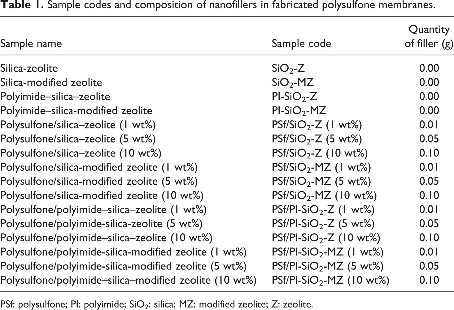
PSf: polysulfone; PI: polyimide; SiO2: silica; MZ: modified zeolite; Z: zeolite.
Results and discussion
Spectroscopic analysis
FTIR spectroscopy of NCs
The FTIR spectra of four nanocomposites namely SiO2-Z, SiO2-MZ, PI-SiO2-Z, and PI-SiO2-MZ are depicted in Figure 1. The FTIR spectrum of SiO2/Z NC shows absorption at 776 cm−1, which confirms the presence of Si–O–Si bond symmetric stretching vibration. 27 The prominent band at 1063 cm−1 is assigned to Al–O bending vibration. The small peak at 2339 cm−1 appears due to hydrogen bonding. As compared to SiO2/Z NC, peak intensities are slightly shifted to higher wavenumber for SiO2/MZ NC due to zeolite modification. The absorption band at 784 cm−1 is related to Si–O–Si bond symmetric stretching vibration. The broadband at 1072 cm−1 confirmed bending vibration of Al–O bond. The N–H bending vibration gives a signal at 1509 cm−1. The intensity of peak at 2339 cm−1 is slightly increased. Hydrogen bonding between zeolite and the amino group of silane might be the reason for increasing peak intensity. 28 Broadband around 3430 cm−1 appears due to the absorption of moisture by porous SiO2-MZ NC. 29
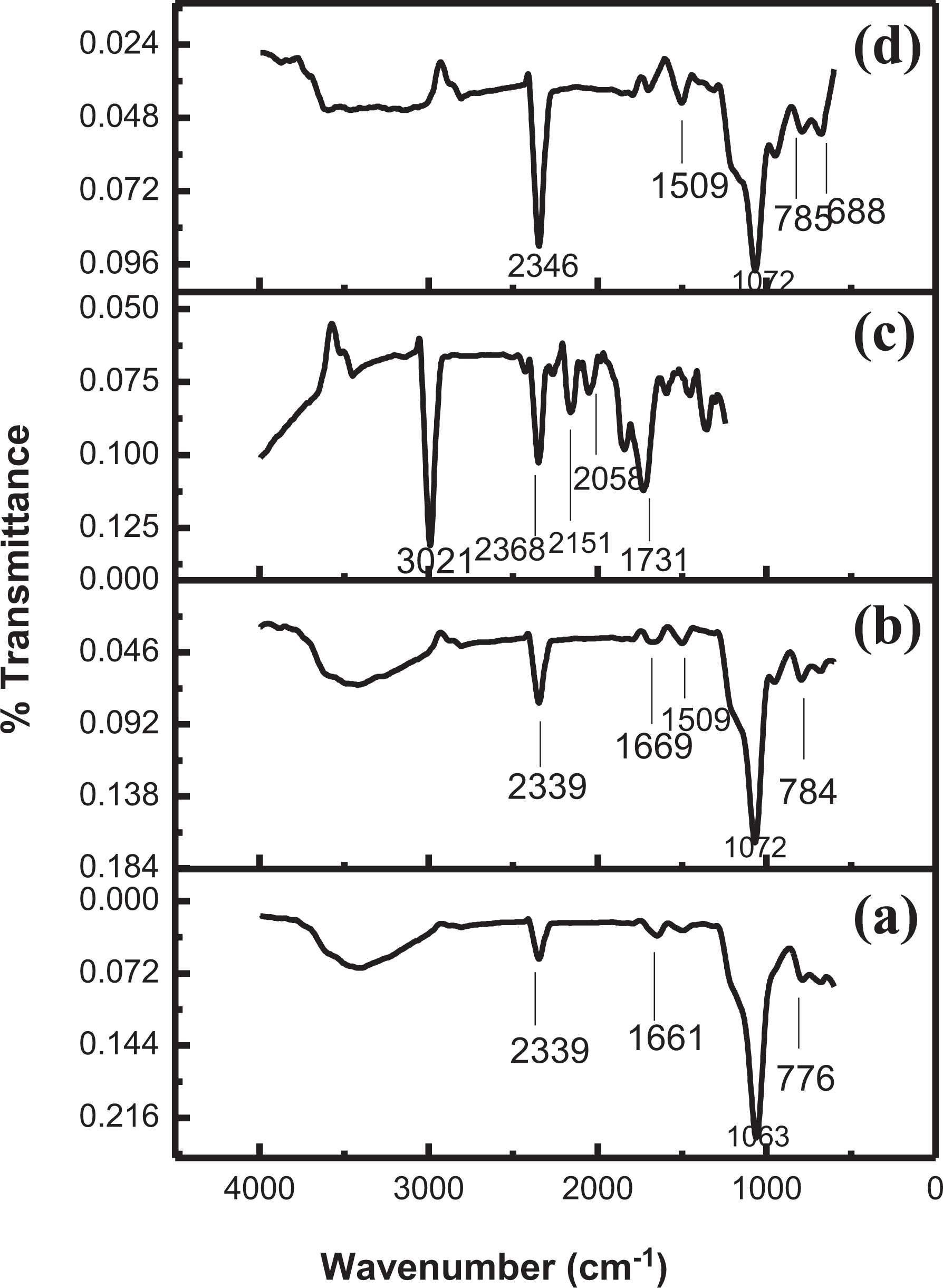
FTIR spectra of (a) SiO2-Z nanocomposite, (b) SiO2-MZ nanocomposite, (c) PI-SiO2-Z nanocomposite, and (d) PI-SiO2-MZ nanocomposite.
The FTIR spectra of PI-SiO2-Z NC (Figure 1(c)) shows a peak at 2368 cm−1, which is attributed to the hydrogen bonding. The Si–OH bond absorption gives signal intensity at 3021 cm−1. Absorption at 1731 cm−1 corresponds to the symmetric stretching vibration of the carbonyl group of imides. For PI-SiO2-MZ NC (Figure 1(d)), the small intensity peak at 688 cm−1 is related to C–S stretching vibration. The absorption band at 785 cm−1 confirmed the presence of Si–O–Si bond symmetric stretching vibration. The broadband at 1072 cm−1 is attributed to imide ring vibration. The medium intensity peak at 1509 cm−1 is due to N–H bending vibration, while the absorption at 2346 cm−1 is attributed to molecular interactions between PI, MZ, and silica nanoparticles. 30
FTIR spectroscopy of fabricated PSf membranes
Figure 2 illustrates the FTIR spectra of PSf membranes reinforced with different NC fillers. The FTIR spectra of PSf/SiO2-Z NCM (Figure 2(a)) exhibit the medium intensity peak at 1097 cm−1, which corresponds to sulfonate group, while the peak at 820 cm−1 is associated to Si–O–Si bond symmetric stretching vibrations. Al–O antisymmetric stretching mode is shown by the peak at 1008 cm−1. The stretching frequency at 1648 cm−1 is due to benzene ring stretching mode. 31 In the FTIR spectrum of PSf/SiO2-MZ NCM (Figure 2(b)), the peak at 689 cm−1 corresponds to C–S stretching vibration, while the absorption at 830 cm−1 confirms Si–O–Si stretching vibrations. The duplets at 1080 and 1145 cm−1 are associated with sulfonate groups. The peak at 1492 cm−1 appears due to C–C stretching vibration in the aromatic ring; while signal intensity at 1570 cm−1 is given by N–H bend.
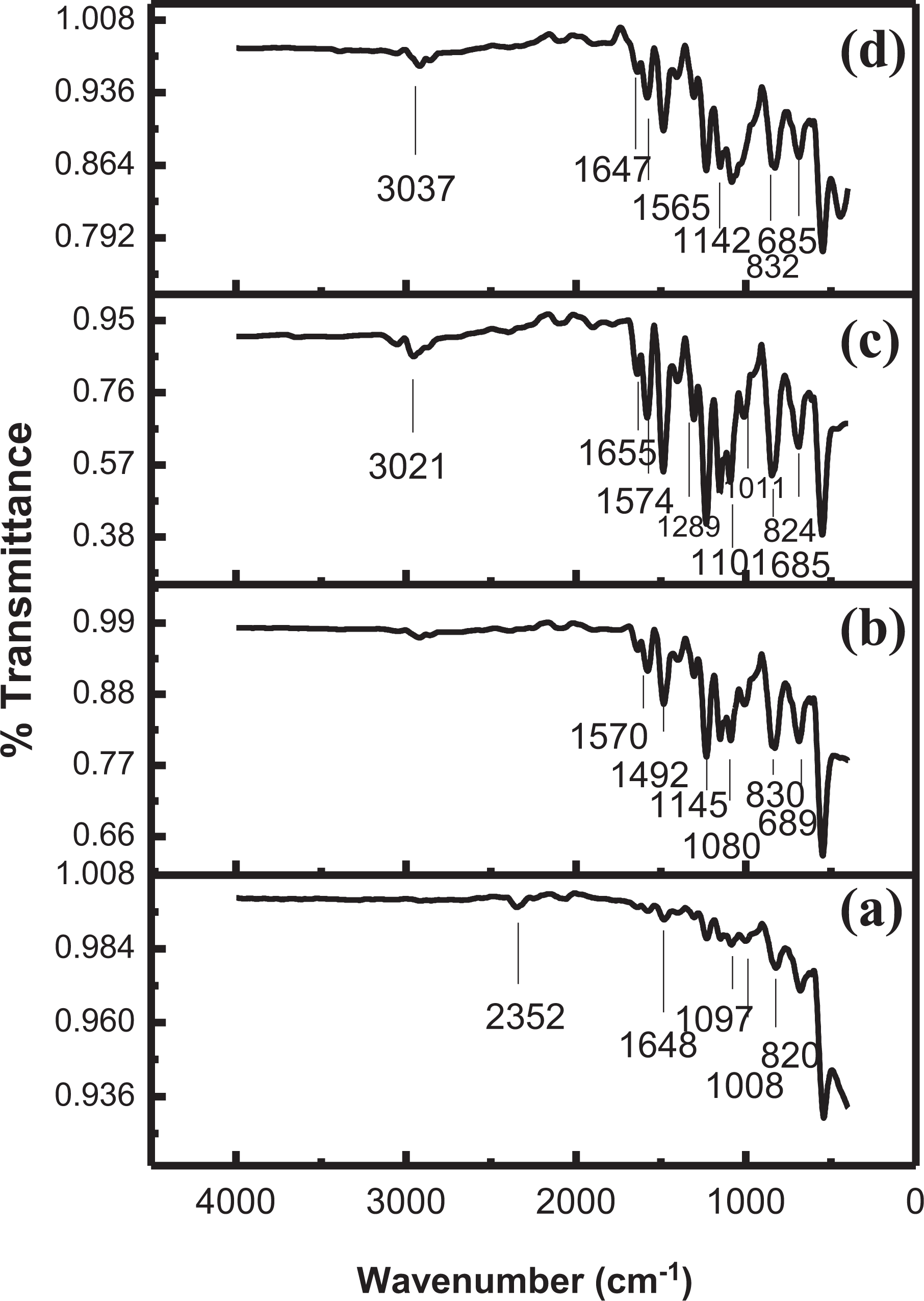
FTIR spectra of 10 wt% of (a) PSf/SiO2-Z nanocomposite membrane, (b) PSf/SiO2 MZ nanocomposite membrane, (c) PSf/PI-SiO2-Z nanocomposite membrane, and (d) PSf/PI-SiO2-MZ nanocomposite membrane.
The FTIR spectrum of PSf/PI-SiO2-Z NCM (Figure 2(c)) indicates the presence of sulfonate group at 1101 cm−1. The absorption at 1574 cm−1 corresponds to N–H bending vibrations while the peak at 3021 cm−1 is attributed to N–H stretching vibrations. C–N–C stretching vibration gives a signal at 1289 cm−1. The C–S stretching vibration is indicated by absorption at 685 cm−1. Absorption at 824 cm−1 corresponds to Si–O–Si symmetric stretching vibration. The small peak at 1101 cm−1 indicates Al–O bending vibration, while absorption at 1655 cm−1 corresponds to symmetrical carbonyl group vibration. The spectroscopic analysis of PSf/PI-SiO2-MZ NCM (Figure 2(d)) reveals a shift of intensities to higher wavenumber as compared to PSf/PI-SiO2-Z NCM. C–S stretching vibration is confirmed at 685 cm−1, while Si–O–Si symmetric stretching vibration is observed around 832 cm−1. Absorption at 1142 cm−1 is due to the presence of sulfonate groups. N–H bending vibration gives a signal at 1565 cm−1. The small peak at 1647 cm−1 is observed due to benzene ring stretching mode. The peak at 3037 cm−1 corresponds to N–H stretching vibrations.
Morphological studies
SEM analysis of NCs
The details about the surface and morphology of NC fillers are shown in Figure 3. The SEM image of SiO2-Z NC (Figure 3(a)) reveals tiny spherical particles. These particles should arise from the silica source. 32 The result indicates low crystallinity, which is consistent with the XRD pattern. The SEM image of SiO2-MZ NC (Figure 3(b)) shows well-defined crystals that appear due to silane modification of the zeolite. 33 The SiO2-Z and SiO2-MZ NC are formed in semi ball and flake like shape. Smooth surface is observed for SiO2-Z NC; however, aggregate and irregular form is observed after modification. The SEM micrographs of PI-SiO2-Z and PI-SiO2-MZ NC look quite similar, as evident from Figure 3(c) and (d). It might be due to a smaller number of grafted silanes and low resolution of instrument that the chemisorbed molecules are not credible to distinguish.
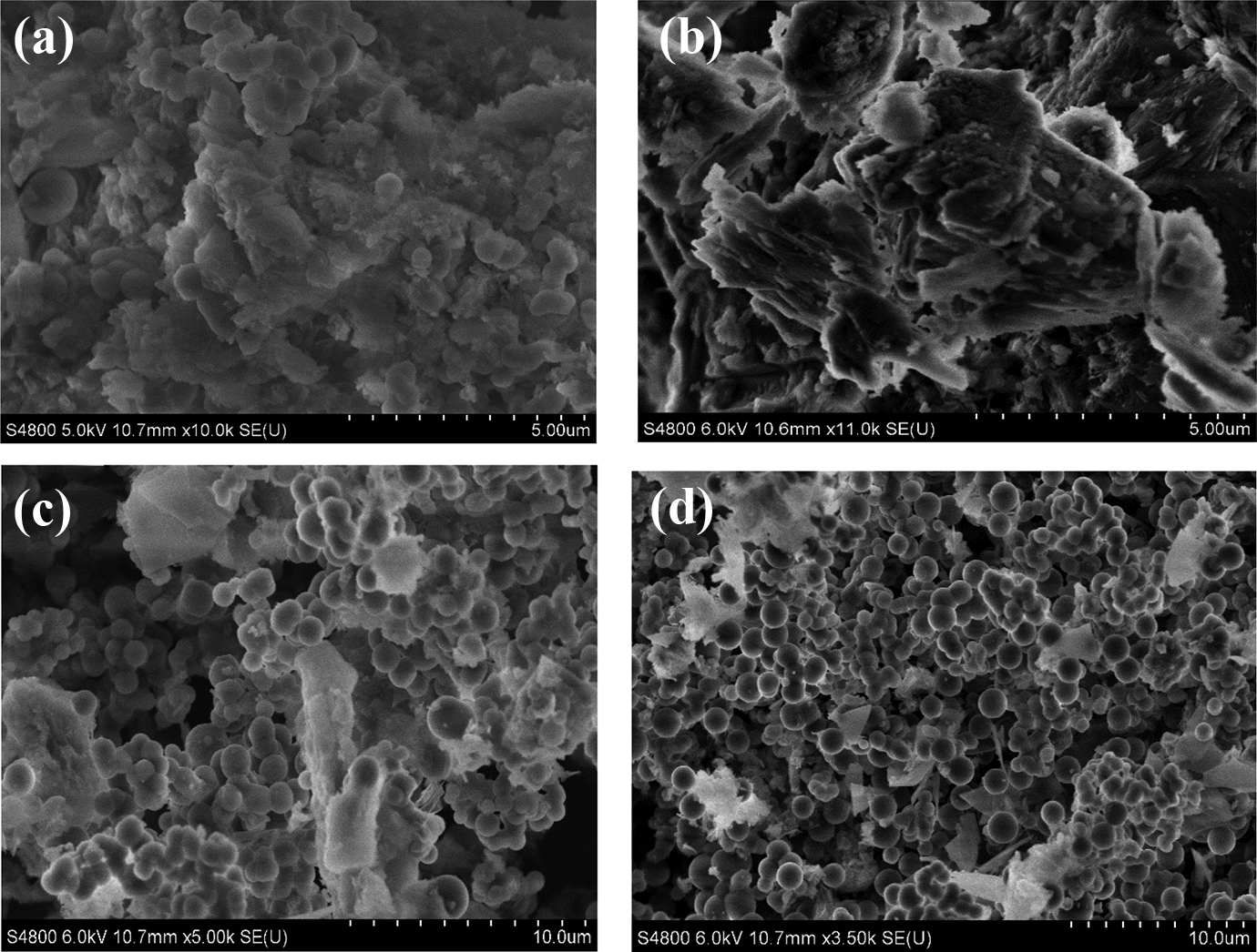
SEM micrographs of (a) SiO2-Z nanocomposite (5 µm), (b) SiO2-MZ nanocomposite (5 µm), (c) PI-SiO2-Z nanocomposite (10 µm), and (d) PI-SiO2-MZ nanocomposite (10 µm).
SEM analysis of fabricated PSf membranes
The surface morphologies of PSf-NCMs are imaged in Figure 4. The dispersion of NC in the polymer matrix is improved in the order of PSf/SiO2-Z < PSf/SiO2-MZ < PSf/PI-SiO2-Z < PSf/PI-SiO2-MZ, as depicted from Figure 4. Particles are not homogenously distributed in the membranes fabricated from PSf/SiO2-Z and PSf/SiO2-MZ. Smooth surface and homogenous morphology are attained by incorporation of PI. The PSf/PI-SiO2-Z and PSf/PI-SiO2-MZ membranes exhibit a uniform distribution of particles in the polymer matrix. Aggregate formation can be prevented in the polymer matrix by improving interfacial adhesion through surface treatment between filler and polymer matrix. 34,35 Pores formed on the surface of the polymer membrane can be classified into two categories: pores formed at filler and polymer interface and pores formed in the polymer matrix. 36 It is evident from the SEM micrographs that slit-like pores are formed in the PSf matrix after reinforcement of nanofillers.
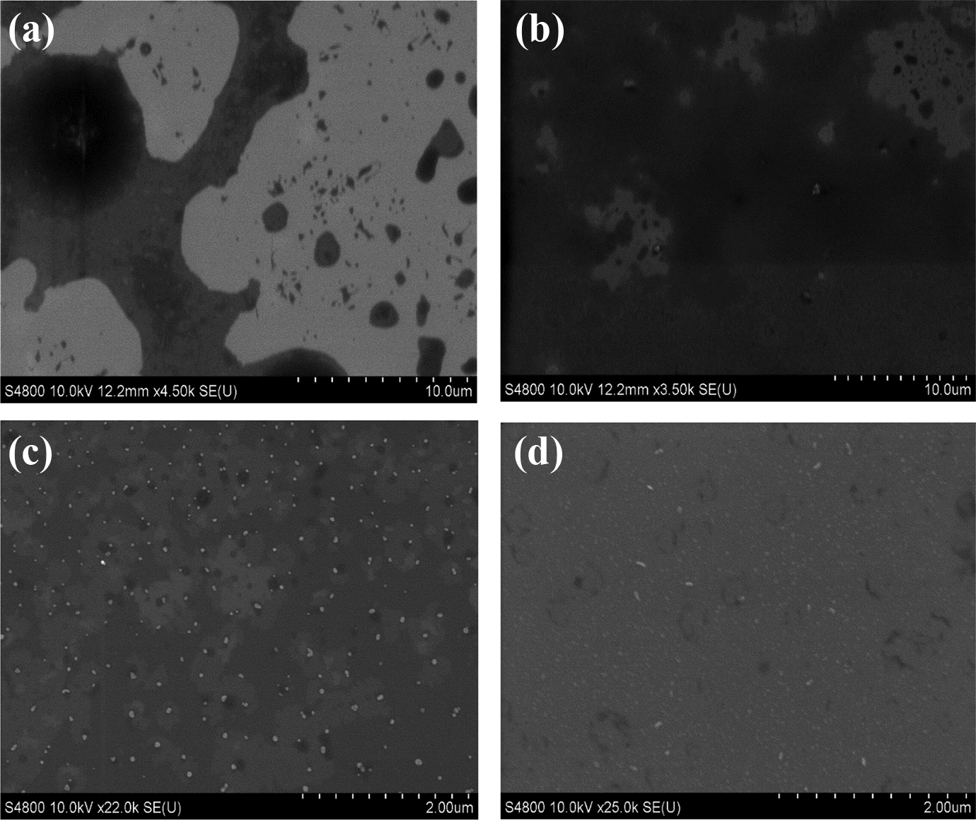
SEM micrographs of (a) PSf/SiO2-Z nanocomposite membrane (10 µm), (b) PSf/SiO2-MZ nanocomposite membrane (10 µm), (c) PSf/PI-SiO2-Z nanocomposite membrane (2 µm), and (d) PSf/PI-SiO2-MZ NCM (2 µm).
TEM analysis of NCs
TEM has proved to be a potential technique for examination of nano-SiO2silica in the zeolite matrix. TEM micrograph of SiO2-Z NC (Figure 5(a)) reveals no distinguished boundary between two phases. Significant difference is observed in the TEM image of SiO2-MZ NC (Figure 5(b)), which displays mesoporous channels packed with zeolite. The TEM image of PI-SiO2-Z NC (Figure 5(c)) exhibits in situ generation of silica nanoparticles in PI and zeolite matrix. Spherical particles possessing diameter around 350 nm is observed. The filler and matrix particles can be distinguished, which indicates perfect bonding between them. 37
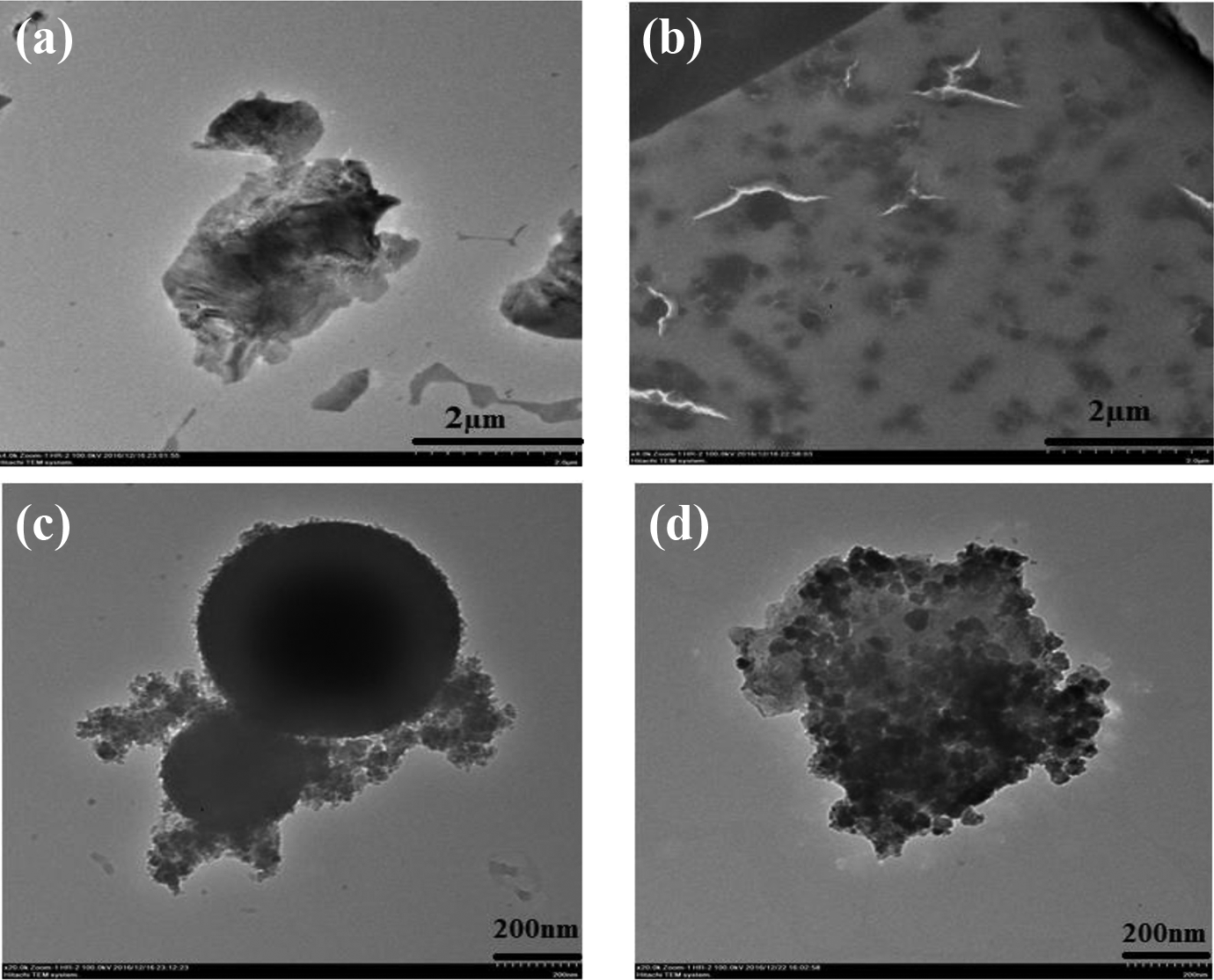
TEM micrographs of (a) SiO2-Z nanocomposite (2 µm), (b) SiO2-MZ nanocomposite (2 µm), (c) PI-SiO2 Z nanocomposite (200 nm), and (d) PI-SiO2-MZ nanocomposite (200 nm).
The TEM image of PI-SiO2-MZ NC (Figure 5(d)) exhibits the molecular sieve-like characteristic with core–shell structure fabricated through CTAB directed sol–gel route. The ordered mesoporous channels are well arranged. The silica shells grow in junction between core and shell predicting retained integrity of zeolite and opened hierarchical PI structure. 38
TEM analysis of fabricated PSf membranes
Figure 6 reveals the surface morphology of polymer NCMs. Broaden and ascendant ridge-valley surface structure is observed for PSf/SiO2-Z NCM (Figure 6(a)). Such structure indicates variation for surface roughness due to SiO2-Z NC loading. The TEM image of PSf/SiO2-MZ NCM suggests the high dispersion quality of nanofillers in the polymer matrix (Figure 6(b)). This behavior is due to silane group treatment. This treatment prevents agglomeration among particles and enhances the filler polymer interaction. 39 Figure 6(c) and (d) exhibits a smoother surface due to increased porosity and hydrophilic nature of the support layer.
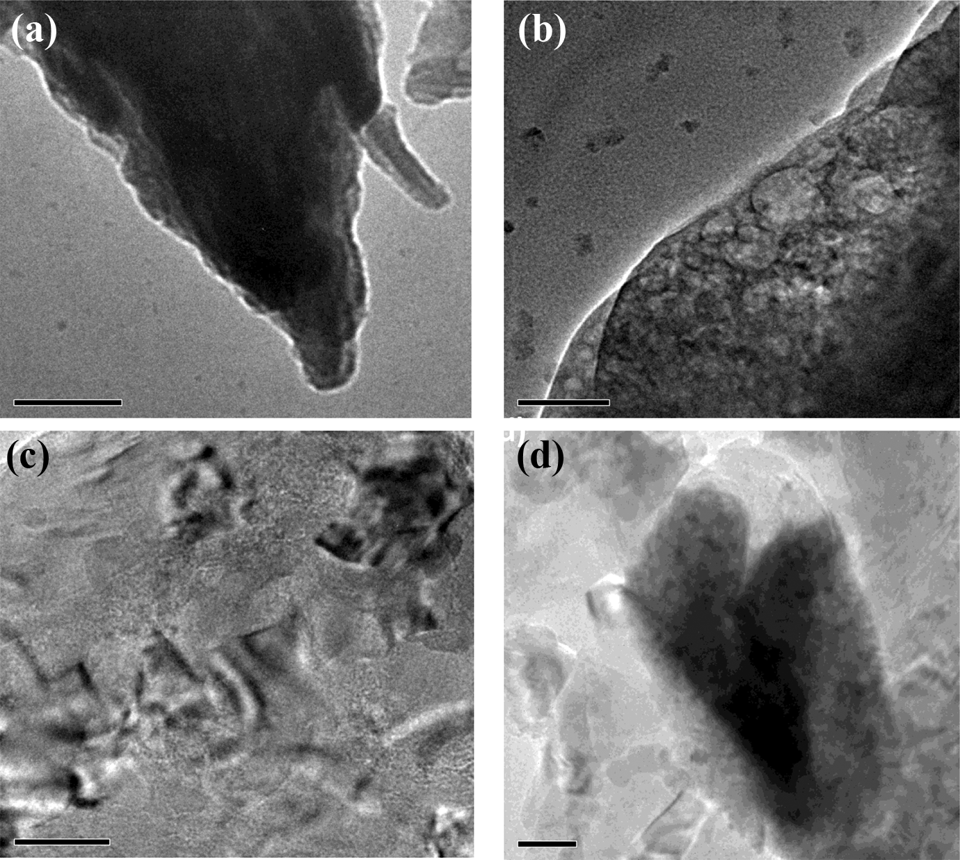
TEM micrograph of (a) PSf/SiO2-Z nanocomposite membrane (100 nm), (b) PSf/SiO2-MZ nanocomposite membrane (50 nm), (c) PSf/PI-SiO2-Z nanocomposite membrane (50 nm), and (d) PSf/PI-SiO2-MZ nanocomposite membrane (50 nm).
Mechanical analysis
The tensile overlay of PSf/SiO2-Z NCM at different concentrations (1, 5, and 10 wt%) is shown in Figure 7(a). For 1 wt% PSf/SiO2-Z NCM, Young’s modulus is evaluated to be 1170 MPa, which has been increased to 1225 MPa for 5 wt% PSf/SiO2-Z NCM. However, on further increasing filler content in the polymer matrix, Young’s modulus is observed to decrease slightly. Agglomeration may result in higher filler concentration and it can initiate breakage. 40 For 10 wt% PSf/SiO2-Z NCM, Young’s modulus is found to be 1109 MPa. The tensile overlay of PSf/SiO2-MZ NCM at varying concentrations (1, 5, and 10 wt%) is represented in Figure 7(b). Young’s modulus is evaluated to be 1284 MPa for 1 wt% PSf/SiO2-MZ NCM, which is increased to 1463 MPa for 5 wt% PSf/SiO2-MZ NCM. On the contrary, Young’ modulus is observed to decrease by 10 wt% PSf/SiO2-MZ NCM. The formation of globular structure at higher concentration can initiate cracks and hence, a decline is observed at higher concentration of filler. 41 For PSf/SiO2-Z NCM and PSf/SiO2-MZ NCM, 5 wt% is evaluated to be the optimum filler concentration.
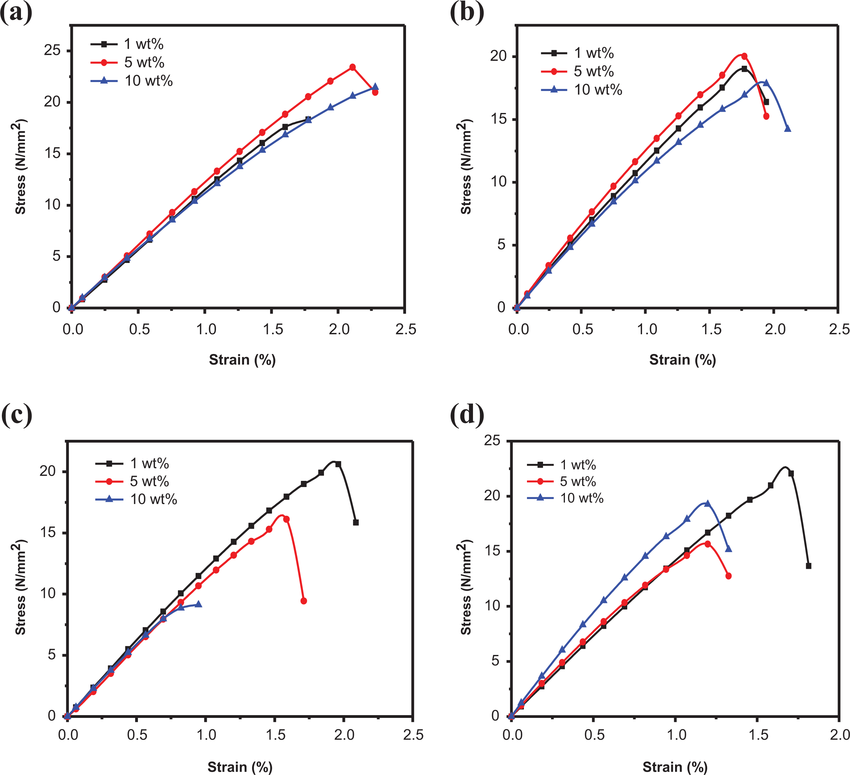
Tensile overlay of (a) PSf/SiO2-Z nanocomposite membrane (1, 5, and 10 wt%), (b) PSf/SiO2-MZ nanocomposite membrane (1, 5, and 10 wt%), (c) PSf/PI-SiO2-Z nanocomposite membrane (1, 5, and 10 wt%), and (d) PSf/PI-SiO2-MZ nanocomposite membrane (1, 5, and 10 wt%).
The tensile overlay of NCM with varying weight concentrations of PI-SiO2-Z NC is represented in Figure 7(c). Young’s modulus is observed to decrease with increasing filler concentration and 1 wt% is observed to be the optimum filler concentration. Weak interactions between polymer and filler are the reason for the decline in Young’s modulus value with increasing filler concentration. A similar trend is observed for toughness of NCMs.
The tensile overlay of PSf/PI-SiO2-MZ NCM, as shown in Figure 7(d), exhibits Young’s modulus value of 1845 MPa for 1 wt% PSf/PI-SiO2-MZ NCM, which is decreased to 1475 MPa for 5 wt% PSf/PI-SiO2-MZ NCM. For 10 wt% PSf/PI-SiO2-MZ NCM, Young’s modulus is further decreased to 1438 MPa. The decrease in Young’s modulus with increasing filler concentration may result due to weak polymer–filler interactions. For both PSf/PI/SiO2-Z NCM and PSf/PI/SiO2-MZ NCM, 1 wt% is evaluated to be the optimum filler concentration. The results of mechanical analysis are summarized in Table 2.
Mechanical properties of fabricated polysulfone nanocomposite membranes.
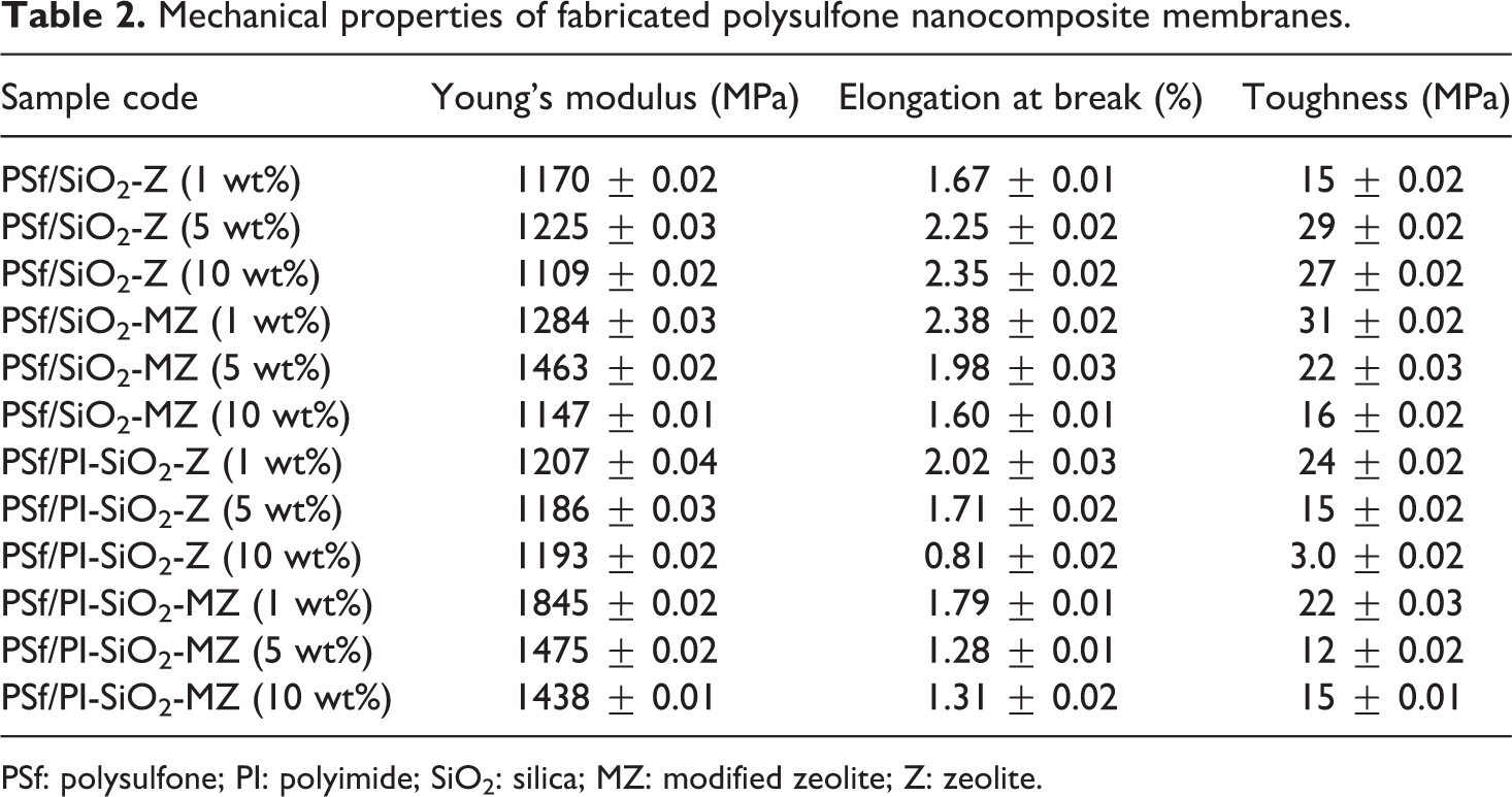
PSf: polysulfone; PI: polyimide; SiO2: silica; MZ: modified zeolite; Z: zeolite.
Sample codes for statistical analysis are as follows: Z1 = PSf/SiO2-Z (1 wt%), Z5 = PSf/SiO2-Z (5 wt%), ZP10 = PSf/PI-SiO2-Z (10 wt%), MZ1 = PSf/SiO2-MZ (1 wt%), MZ5 = PSf/SiO2-MZ (5 wt%), and MZP10 = PSf/PI-SiO2-MZ (10 wt%).
Box plots are presented in Figure 8 to observe the effect of different nanofillers on Young’s modulus (a) and elongation at break (%) (b) values of 12 different NCMs. The box plot for toughness is given in Figure S1 in supporting information. Analysis of variance has been used to statistically observe the effect of different nanofillers on mechanical properties of all NCMs.
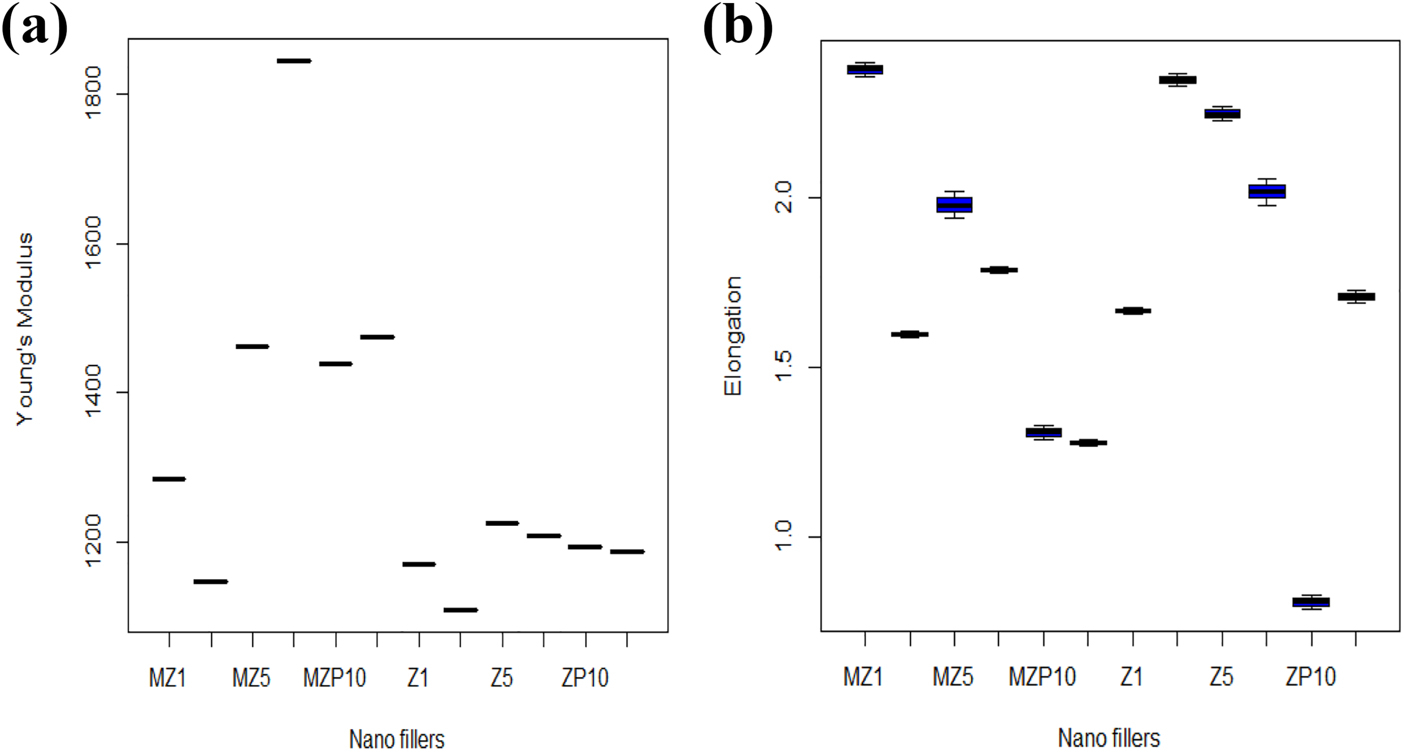
Box plot showing the effect of different nanofillers on (a) Young’s modulus, (b) elongation at break (%) for different nanocomposite membranes obtained from analysis of variance test.
Figure 8(a) shows that Young’s modulus values for all different NCMs are significantly different from each other. Furthermore, Tukey multiple comparisons test have been done to identify the nanofillers, which have significantly different results from others. The probability, P, value given in Table S1 (supplementary information) for Young’s modulus for all samples comes out to be zero, which is less than 0.05, indicating that the effect of different compositions of nanofillers is significantly different from each other. The results of Tukey multiple comparisons test conducted for elongation at break (%) and toughness of different NCM are given in Tables S2 and S3, respectively. It is observed that most of the nanofillers have a different effect from each other on the above-mentioned mechanical properties of different NCM except for few with P value greater than 0.05. Overall, all NCMs are statistically different from each other.
Thermal analysis
The differential scanning calorimetry (DSC) curves of PSf/SiO2-Z NCM are represented in Figure 9(a). For 1 wt % PSf/SiO2-Z NCM, glass transition temperature (Tg) is observed at 89°C; while for 5 wt%, PSf/SiO2-Z NCM, Tg appears at 90°C. For 10 wt% PSf/SiO2-Z NCM, Tg is noticed at 96°C. Therefore, Tg is observed to increase with increasing filler concentration as rigidification occurs due to hindrance of polymer chain movement at the polymer–filler interface. 42
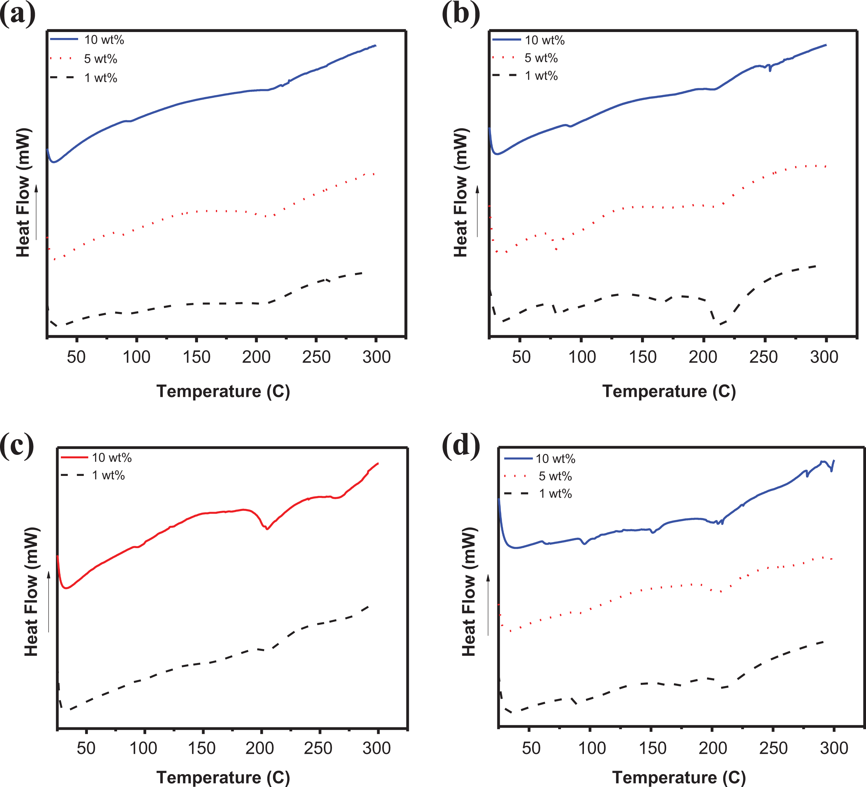
DSC curves of (a) PSf/SiO2-Z NCM (1, 5, and 10 wt%), (b) PSf/SiO2-MZ NCM (1, 5, and 10 wt%); (c) PSf/PI-SiO2-Z NCM (1 and 10 wt%), and (d) PSf/PI-SiO2-MZ NCM (1, 5, and 10 wt%).
Figure 9(b) illustrates the DCS curves of PSf/SiO2-MZ NCM. It shows two distinct regions. The first one corresponds to the glass transition temperature, while the second one is attributed to the melting temperature. The glass transition temperature for 1 wt% PSf/SiO2-MZ NCM appears at 79°C while melting temperature (Tm) is observed at 216°C. For 5 wt%, PSf/SiO2-MZ NCM Tg appears at 81°C, while for 10 wt% PSf/SiO2-MZ NCM, Tg is observed at 91°C. Therefore, an increasing trend in Tg is observed with increasing SiO2-MZ concentration in the PSf matrix. Moreover, polymer membranes reinforced with SiO2-Z filler depict improved thermal properties as compared to membranes reinforced with SiO2-MZ filler. Zeolite modification causes lowering of Tg of fabricated samples due to the presence of flexible aminosilane groups.
The DSC curves of PSf/PI-SiO2-Z NCM are shown in Figure 9(c). Tg is observed at 206°C for 1 wt% PSf/PI-SiO2-Z NCM while it is increased to 208°C for 10 wt% PSf/PI-SiO2-Z NCM. Considerable increase is observed in glass transition temperature values of PI incorporated NCMs. This increase is attributed to the better interaction and good compatibility of PSf and PI. 43 The DSC curves of PSf/PI-SiO2-MZ NCM are depicted in Figure 8(d). The Tg value for 1 wt% PSf/PI-SiO2-MZ NCM is observed at 91°C, which is slightly improved to 94°C for 10 wt% PSf/PI-SiO2-MZ NCM. In this case, the presence of aminosilane groups may initiate chain flexibility, which results in lowering of Tg values. Tm for 1 wt% of PSf/PI-SiO2-MZ is observed at 211°C.
X-Ray diffraction analysis
The small-angle XRD patterns of NC fillers are shown in Figure 10. For SiO2-Z NC, small diffraction peak is observed at 2θ value of 2.34° referring to d-spacing value of 37.71, which is ascribed to the ordered structure of zeolite. However, the broadband also appeared in the 2θ range of 22–26°. Bragg peak is given by SiO2-Z NC at a low angle. XRD peaks commonly disappear or broaden with a decrease of ordered domain area. 44 For SiO2-MZ NC, low crystalline diffractogram is recorded with a slight shift in peak position from 2.34° to 2.41° relating to d-spacing value of 36.52 due to MZ addition. The broadband in the range of 22–26° is also recorded.
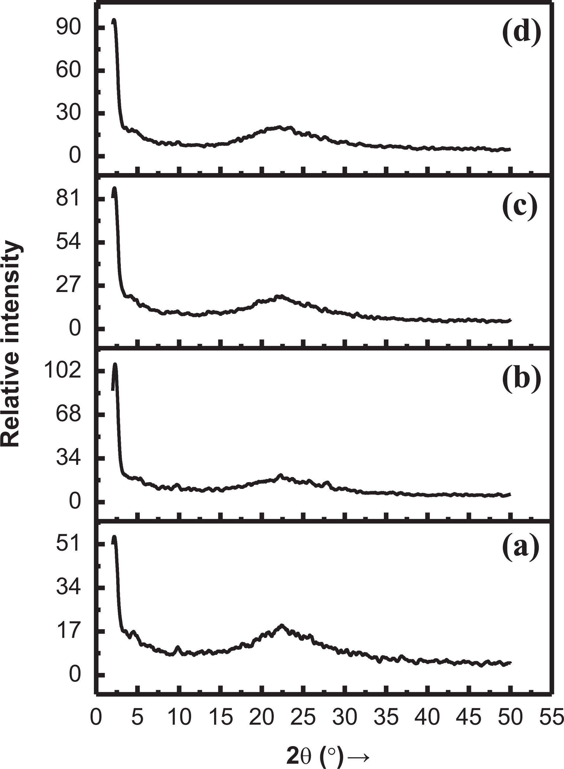
XRD spectrum of (a) SiO2-Z NC, (b) SiO2-MZ NC, (c) PI-SiO2-Z NC, and (d) PI-SiO2-MZ NC.
XRD result of PI-SiO2-Z NC is shown in Figure 10(c). In PI-Z intergrowth silica, usually, a single line appears at 2θ value of 2.45° referring to d-spacing value of 36.00; while a band in the 2θ range of 22–26° is also recorded. The generation of imide linkage in silica/MZ NC shifts peak position to 2θ value of 2.08° referring to d-spacing value of 42.24. The broadband in the range of 22–26° is also investigated. The fabricated nanocomposites thus exhibit the semicrystalline nature by revealing the broad peak as well as narrow diffraction peaks.
Membrane property measurements
The average value of the results of swelling tests repeated thrice is depicted in Table 3. The SD of NCMs is observed to increase with the addition of filler. However, the decreasing trend is observed for SD of membranes while moving from water to propanol as SD is dependent on hydrophilicity of solvent. The trend of NCM for SD in various solvents was recorded and given below. Optimal results were exhibited by membranes evaluated with water.
Swelling degree (%) of fabricated polysulfone nanocomposite membranes.
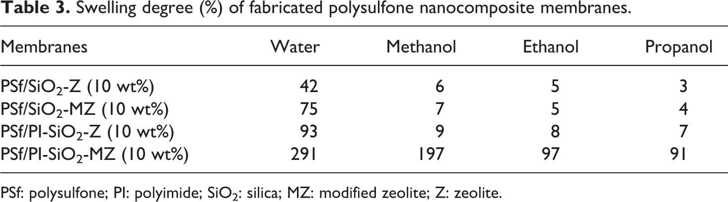
PSf: polysulfone; PI: polyimide; SiO2: silica; MZ: modified zeolite; Z: zeolite.
Water > Methanol > Ethanol > Propanol
Membrane porosity has close contact with the morphology. 45 –47 Table 4 depicts the average of porosity values of fabricated NCMs. Addition of the filler has considerably increased the porosity of polymer membrane because filler addition has enhanced the hydrophilic nature of the membrane. However, porosity is observed to decrease while moving from water to less hydrophilic solvent.
Porosity of fabricated polysulfone nanocomposite membranes.
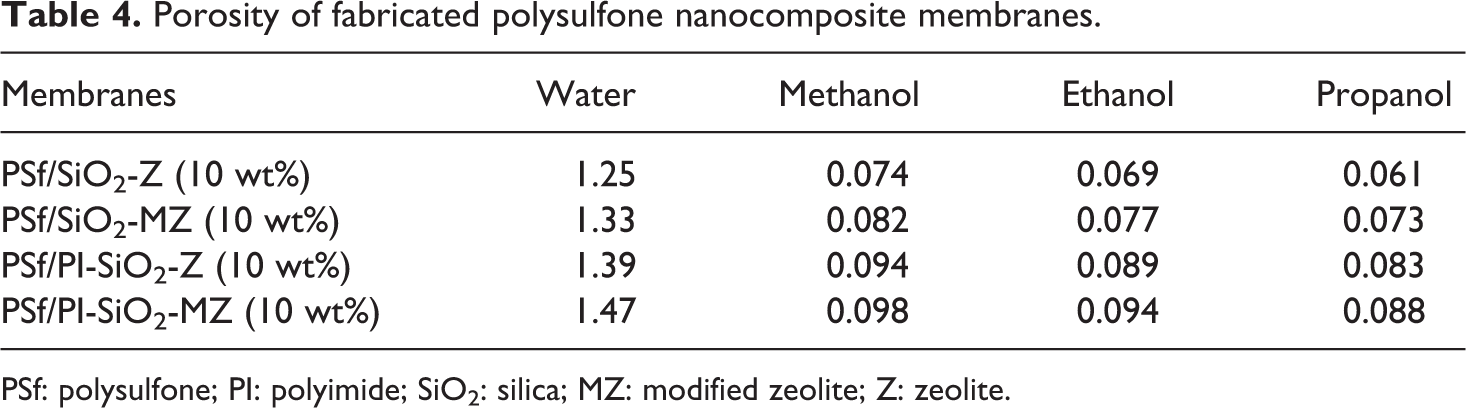
PSf: polysulfone; PI: polyimide; SiO2: silica; MZ: modified zeolite; Z: zeolite.
Antibacterial activity of nanoSiO2-MZ-incorporated polymer membranes
The photographic images of zone of inhibition against Salmonella typhi, Klebsella pneumonia, Bacillus subtilis, and Staphylococcus aureus are shown in Figure 11. Enough mean inhibition zone diameter was evaluated against S. Typhi and K. pneumonia for fabricated NCMs. PSf/SiO2-Z did not show any activity against gram-negative bacteria, however, PSf/SiO2-MZ and PSf/PI-SiO2-Z revealed good activity against gram-negative bacteria. Much better activity was shown by PSf/PI-SiO2-MZ NCMs. Potential increase was observed in death rate of microbes. All fabricated NCMs exhibited good activity against B. subtilis and S. aureus, but the maximum activity was revealed by PSf/PI-SiO2-MZ NCM. Superior structural integration of PSf, PI, SiO2, and MZ was responsible for better antibacterial activity. The results sustained and PSf/PI-SiO2-MZ NCM revealed the best antibacterial activity against gram-negative and gram-positive bacteria among all fabricated NCMs. Thus, the combination effect of PSf, PI, SiO2, and MZ in the present work exhibited considerable antibacterial activity. The differences observed in inhibition zones against bacteria for NCMs are reported in Table 5.
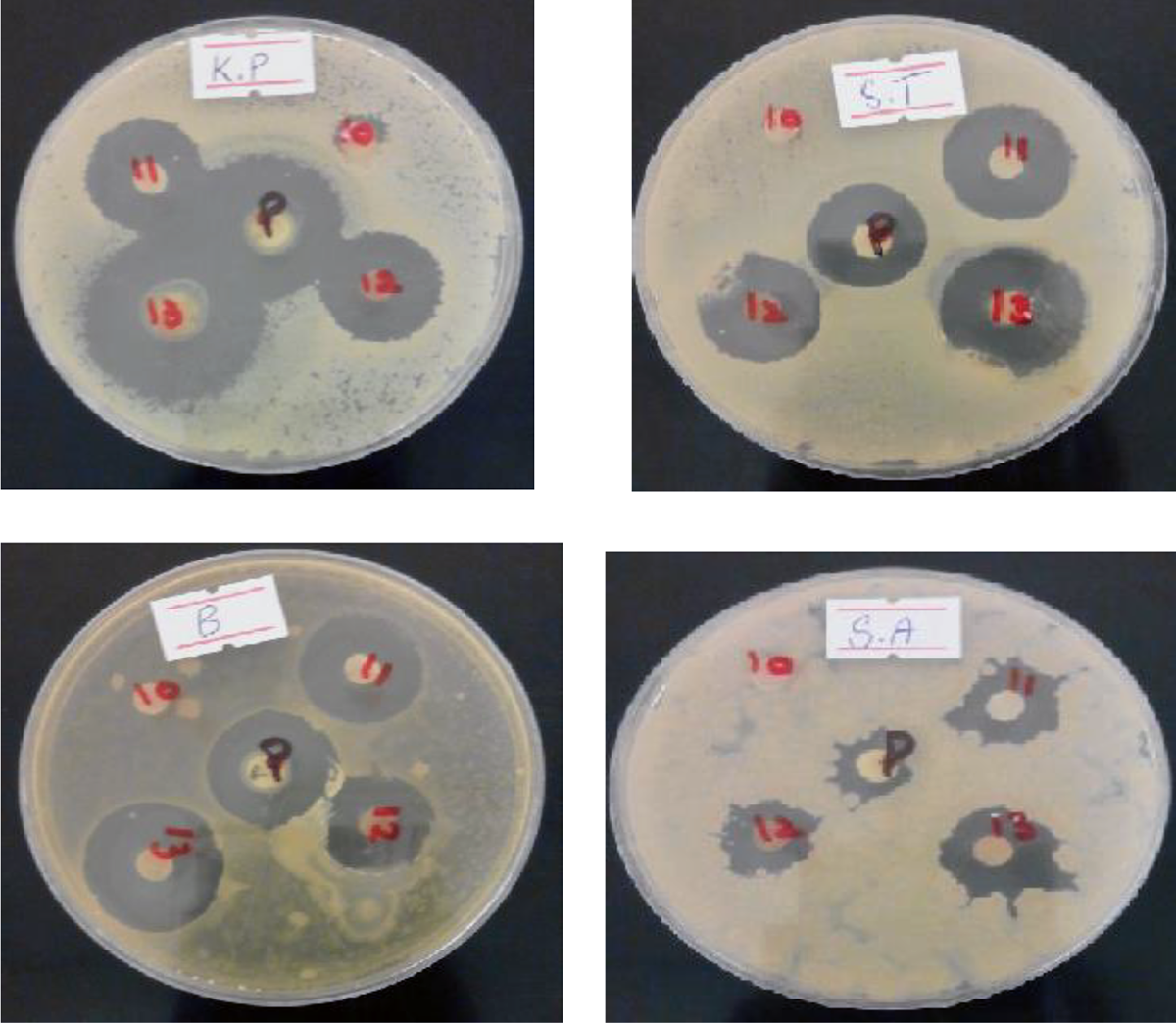
Antibacterial activity of fabricated polysulfone membranes; inhibition zones are labeled as 10 = PSf/SiO2-Z (10 wt%); 11 = PSf/SiO2-MZ (10 wt%); 12 = PSf/PI-SiO2-Z (10 wt%); 13 =PSf/PI-SiO2-MZ (10 wt%), against K.P (Klebsella pneumonia), S.T (Salmonella typhi), B (Bacillus subtilis), and S.A (Staphylococcus aureus).
Differences observed in inhibition zones (Salmonella typhi, Klebsella pneumonia, Bacillus subtilis, and Staphylococcus aureus) for fabricated polymer nanocomposites.
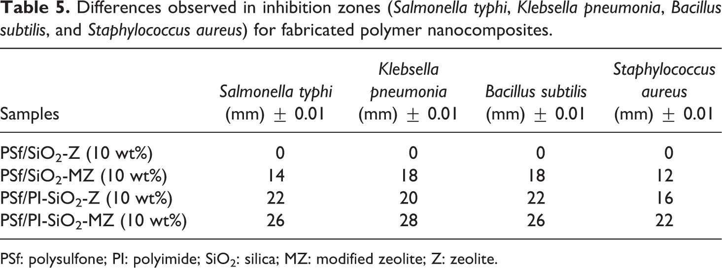
PSf: polysulfone; PI: polyimide; SiO2: silica; MZ: modified zeolite; Z: zeolite.
Generally, the PSf/PI-based NCMs have been used as ultrafiltration and gas separation applications. 48,49 These fabricated membranes with efficient antibacterial and good thermal and mechanical properties can be used in biomedical applications.
Conclusion
In the current study, the effect of the addition of SiO2-MZ-based nanofiller on thermal, mechanical, structural, and antibacterial properties of PSf-based NCM has been investigated. Solution casting technique was employed to fabricate the NCMs. Silane treatment of zeolite particles was performed, and SiO2 nanoparticles were in situ generated in the MZ suspension. The filler particles were loaded in the polymer matrix at different concentrations (i.e. 1, 5, and 10 wt%, respectively). PI was successfully fabricated through polyamic acid route and its synthesis was confirmed by FTIR spectrum. Both PSf and PI were figured out to be compatible. SEM analysis revealed that incorporation of PI in PSf matrix results in smooth surface and homogeneous morphology for PSf/PI-SiO2-MZ NCM as compared to PSf/SiO2-MZ NCM. The PSf/PI-SiO2-Z and PSf/PI-SiO2-MZ membrane exhibit uniform distribution of particles in the polymer matrix. This can be attributed to the good compatibility between PSf and PI.
The in situ generation of silica nanoparticles can be observed through the TEM analysis of PI-SiO2-Z NC. High strength and better mechanical properties are observed for NCMs. The highest value of Young’s modulus was evaluated for 1 wt% PSf/PI-SiO2-MZ NCM. The thermal analysis revealed an increase in Tg values with increasing filler concentration. The XRD analysis of fabricated nanocomposites exhibited the semicrystalline nature by illustrating the broad as well as narrow diffraction peaks. The membrane property measurements revealed that swelling capacity in different solvents was in the order of H2O > methanol > ethanol > propanol. Considerable increase was observed in the porosity of polymer membrane by addition of the nanofiller as filler addition enhanced the hydrophilic nature of the membrane. Moreover, membrane properties were observed to improve for PSf/PI-SiO2-MZ NCM as compared to PSf/SiO2-Z NCM. To sum up, PSf NCM fabricated with PI SiO2-MZ nanofiller was found to have improved mechanical, thermal, and potential antibacterial properties as compared to neat PSf membranes. New dimensions are provided for the development of novel functional materials at nanoscale with an inimitable combination of properties.
Supplemental material
Supplemental Material, SUPPLEMENTARY_MATERIAL - Fabrication of silica-modified zeolite-based polysulfone nanocomposite membranes: Enhanced thermal, mechanical, and antibacterial properties
Supplemental Material, SUPPLEMENTARY_MATERIAL for Fabrication of silica-modified zeolite-based polysulfone nanocomposite membranes: Enhanced thermal, mechanical, and antibacterial properties by Sedra Tul Muntha, Jaweria Ambreen, Muhammad Siddiq, Hina Naeem, Saz Muhammad and Anum Khan in Journal of Thermoplastic Composite Materials
Footnotes
Funding
The author(s) disclosed receipt of the following financial support for the research, authorship, and/or publication of this article: The authors received financial support for this research from Quaid-i-Azam University research fund 2017-2018 and do not compete for any financial interest.
Supplemental material
Supplemental material for this article is available online.
References
Supplementary Material
Please find the following supplemental material available below.
For Open Access articles published under a Creative Commons License, all supplemental material carries the same license as the article it is associated with.
For non-Open Access articles published, all supplemental material carries a non-exclusive license, and permission requests for re-use of supplemental material or any part of supplemental material shall be sent directly to the copyright owner as specified in the copyright notice associated with the article.