
Abstract
The increase in demand for natural fibers in development of the composites has grown rapidly due to the cost-effectiveness, low density, biodegradability, and renewability. The lack of appropriate interfacial bonding between the cellulose fibers and the thermoplastic matrix is one of the disadvantages faced during their application. Also, the properties of composite made of thermoplastic polystyrene (PS) and cellulose acetate fibers are not compatible due to the poor wettability and interfacial adhesion. In the study presented, PS reinforced with cellulose triacetate is being prepared by melt blending in a twin-screw extruder with the induction of fusabond (FB). The influence of the cellulose acetate and FB content on PS composite is being investigated using thermogravimetric analysis, tensile test, dynamic mechanical analysis, scanning electron microscopy, and X-ray photoelectron spectroscopy. The addition of FB enhances interfacial adhesion demonstrated by the improvement in storage modulus, reduction in damping peak value, and the increase in thermal stability of the composite. The inclusion of FB not only increases the % elongation but also improves the impact strength of the cellulose triacetate-reinforced PS composite under dynamic loading. Moreover, the interaction between PS with cellulose triacetate fiber is indicated by the results of X-ray photospectroscopy and fracture surface morphology. The results show that the addition of FB is suitable for use in cellulose fiber-reinforced PS composite for packaging, automotive, and biomedical applications.
Keywords
Introduction
The natural fibers are becoming a preferential material choice when it comes to the reinforcement materials for thermoplastic composites. The natural fibers can be cellulose, bamboo, palm, pine, jute, and sisal. The natural fibers are superior to synthetic fibers because they are biodegradable and the products made by the natural fiber are sustainable. Cellulose can be sourced naturally from wood or lint attached to cotton seeds. Cellulose is made of repeating glucose units that have the chemical formula C6H7O2 (OH)3. 1 Also, cellulose is found plentifully in nature as it occurs in all plant cell walls (i.e. flax, hemp, kenaf, and ramie) and can also be synthesized by some bacteria (i.e. gluconacetobacter, agrobacterium, pseudomonas, rhizobium, and sarcin). 2,3 The products made with cellulose fiber-reinforced thermoplastic composites can have improved specific strength as they have low density and stiffness. 4,5 Moreover, the toughness and strength of manufactured goods will be better than their predecessors. Also, the cellulose fibers are cost-effective, adaptable, and biodegradable. The cellulose fiber minimizes the wear of machinery in comparison to synthetic fiber 6 and the use of cellulose fiber in the products minimizes the health hazards. Moreover, the two types of nano reinforcements that can be obtained from plant cellulose are nanofibrillated cellulose (NFC) and nanocrystalline cellulose (NCC). Several studies center on bionanocomposites, which uses natural fiber due to their abundance and potential for substituting carbon fiber and glass fiber in the future. 7 NCCs serve as a suitable renewable alternative for bionanocomposites due to its nanoscale cellulose fiber composition, high strength and stiffness, low weight, biodegradability, and application in the development of nanocomposite material. 8,9
The cellulose has remarkable reinforcing properties due to its abundant hydroxyl group within the large surface area, but the absence of appropriate interfacial bonding between the cellulose fibers and the thermoplastic matrix is a major disadvantage. 10,11 The reason behind the weak interfacial bonding is the hydrophobic nature of thermoplastic matrix and hydrophilic characteristic of cellulose fiber. The incompatibility of cellulose fiber and thermoplastic matrix causes the adhesion to be weaker and the dispersion of the fiber to be inhomogeneous. The composite generated have inferior quality and properties because of inhomogeneous dispersion, which results in the agglomeration of fibers. 10
The use of coupling agent can improve the interfacial adhesion between the cellulose and the matrix. In addition, the presence of a coupling agent will also help the transfer of load in between the matrix and fiber uniformly. 11 Furthermore, the enhancement in properties with the help of coupling agent occurs because of immobilization of the matrix chain and improvement in bonding.
The thermal analysis is helpful in establishing a better understanding of the thermal stability and structure of the intended material. The thermal analysis will also be useful in studying the moisture content, weight loss, and volatility as these factors effect on the degradation and processing condition of the composite. The decomposition of natural fiber occurs in two or three stages under the process of weight loss, which is performed in the controlled temperature between 25°C and 800°C. 12 -15
The dynamic mechanical analysis (DMA) can be also be used to examine the outcome of temperature on the mechanical properties of the composite. The study of viscoelasticity of the intended composite will help to predict the behavior of composite under dynamic stress. Dong and Gauvin 16 used DMA study and have reported extensively on the viscoelastic characteristics of interfacial region of the carbon fiber-reinforced epoxy composite. Guo and Ashida 17 have described the dynamic moduli (G′ and G″) and loss tangent (tan δ) of polyethylene terepthalate fiber-reinforced thermoplastic elastomer by utilizing DMA. Hwang et al. 18 inspected the orientation, aspect ratio, and interlaminar stress of the fiber on the damping behavior of the composite.
Hwang et al. 18 accounted for dynamic viscoelastic characteristics of low-density polyethylene composites reinforced with short sisal fibers and pineapple fibers. George and Mohanty et al. 19,20 examined the variability in the damping modulus (G′, G″) and tan δ by combining coupling agent with jute fiber and high-density polyethylene (HDPE) polymer. Huang and Zhang 21 investigated the interaction of HDPE and wood particles by considering the dynamic and mechanical properties. The result of Huang and Zhang showed that when the agglomeration of wood particles is decreased, the storage modulus is enhanced.
The aim of the intended study is to explore the performance of cellulose triacetate fiber (CF)-reinforced polystyrene (PS) composite. The study was conducted by investigating thermal, mechanical, and dynamic mechanical properties. The Fusabond MB100 D (FB) is being used as a coupling agent in the CF-reinforced PS composite.
Experiment
Preparation
PS (Petrochemical (M) Sdn. Bhd., Pasir Gudang, Johor, Malaysia) was extruded with CFs (Arabian Japanese Company, LLC, KSA) and FB E MB 100 D (Dupont, Michigan, USA) in variable concentrations. The FB E MB 100 D is maleic anhydride-grafted HDPE, which contains high graft level and can also be used as an interfacial modifier to enhance the adhesion. The pellets of PS were initially dried in a vacuum oven at a temperature of 60°C for 12 h to remove moisture before processing through the twin-screw extruder. The CF had average fiber length, which was within 0.3 ≤ LW ≤ 0.4 mm and diameter of 10 µm. The fiber length and diameter were determined by measuring the length of 250 fibers. The PS was reinforced with four concentrations of 10, 20, 30, and 40% wt of cellulose triacetate with the induction of FB MB-100D (3–5 wt.%) as a coupling agent. The extruder was operated at 180°C with a screw speed of 90 rev min−1. The PS/CF/FB composites were blended for 30 min. Finally, the PS composites were injection molded at 150°C and pressed into the test specimen die for 10 min.
Characterization
The thermal stability of cellulose triacetate-reinforced PS composite was characterized using TGA Q50 (TA Instruments, Newcastle, USA) having an accuracy of ±1°C. The alumina pan was used to contain 10 mg samples of composite, and the samples were heated from 20°C to 600°C at a heating rate of 10°C min−1 under nitrogen atmosphere.
The DMA 242 (Netszch, Germany) was used to determine the loss modulus G′, storage modulus G″, and loss factor (tan δ) of the specimens as a function of temperature using dual cantilever having specimen dimensions of 40 × 12 × 5 mm3. The measurements were performed at a frequency of 1 Hz, a strain rate of 0.1% with the heating rate of 2°C min−1, and the temperature range from 20°C to 100°C.
The tensile tests were carried out with the use of Instron Tensile Testing machine (Instron, Norwood, USA) of 50 kN with load accuracy of 0.05%. The prepared samples were loaded at a constant 5 mm min−1 crosshead speed and 0.50-N preload. The three samples having the geometry of ASTM D638 type IV for each composition were tested at 25°C.
The Charpy test was performed with JB W300 J impact testing machine (Test lab, Poland). The potential impact energy, raise angle, and impact speed of the testing machine were 150 ± 1 J, 150° and 5.2 m s−1, respectively. According to ASTM D256, the dimensions of samples were 10 × 10 × 55 mm3 having a notch size of 2 mm.
The morphology of the fracture surface of the PS/CF/FB composites was observed with a JEOL JSM-7600F field-emission scanning electron microscope (Peabody, Massachusetts, USA) at an accelerating voltage of 10 kV.
The XPS measurements were made on an XR 50 spectrometer (SPECS GmbH, Germany) operating at a base pressure of 1 × 10⁻⁸ mbar. A dual-anode non-monochromatic magnesium Kα X-ray source was used to irradiate the sample surface with 13.5 kV and 150 W. The sample was positioned at a take-off angle of 90° between the sample surface and the direction of photoelectrons. The XPS data were acquired utilizing a PHOIBOS 150 MCD-9 hemispherical energy analyzer operating in fixed analyzer transmission mode with an accuracy of ±1% mass concentration. During all characterization technique, each sample was tested three times to verify the results of PS/CF/FB composite.
Results and discussion
The thermal decomposition of neat PS and PS/CF composite at the temperature range of 30–600°C are presented in Figure 1(a). The decomposition and degradation of neat PS initiated at 343°C also shows the complete thermal depolymerisation at 462°C. The first weight loss appears between 330°C and 370°C with the addition of 10% CF, which is related to heat vaporization of water. Meanwhile, the thermal depolymerization of PS and degradation of CF causes the second drop of weight, which starts at 377°C and finishes at 468°C. 20 The introduction of 20%, 30%, and 40% CF in PS provides analogous behavior with a slight deviation in temperature, as shown in Figure 1(a) and Table 1. The outcome of experimental data demonstrates that the gradual addition of CF in PS has insignificant consequences on the thermal decomposition temperature. The thermal decomposition of PS/20%CF with the addition of 3% and 5% FB is shown in Figure 1(b) as an example. The figure shows that the first weight drop happens at 331°C. Meanwhile, the main degradation starts at 379°C and comes to an end at 474°C. The exploration demonstrates that the thermal stability of PS/CF composite is not influenced by the addition of FB.
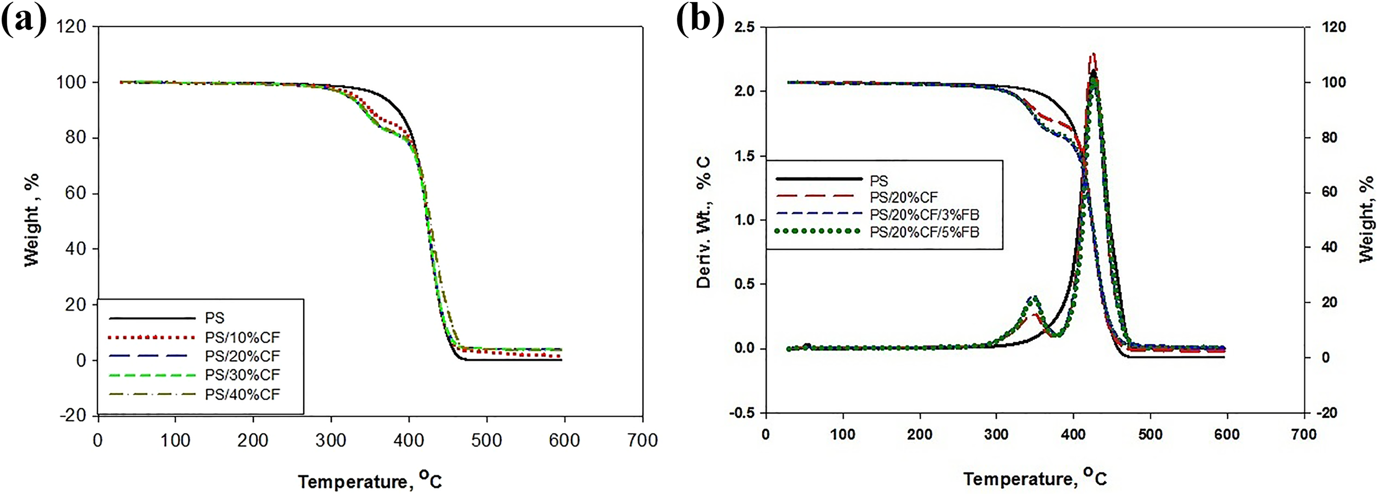
(a) TG curves of PS/CF (b) TG/DTG curves of PS, PS/CF, and PS/CF/FB.
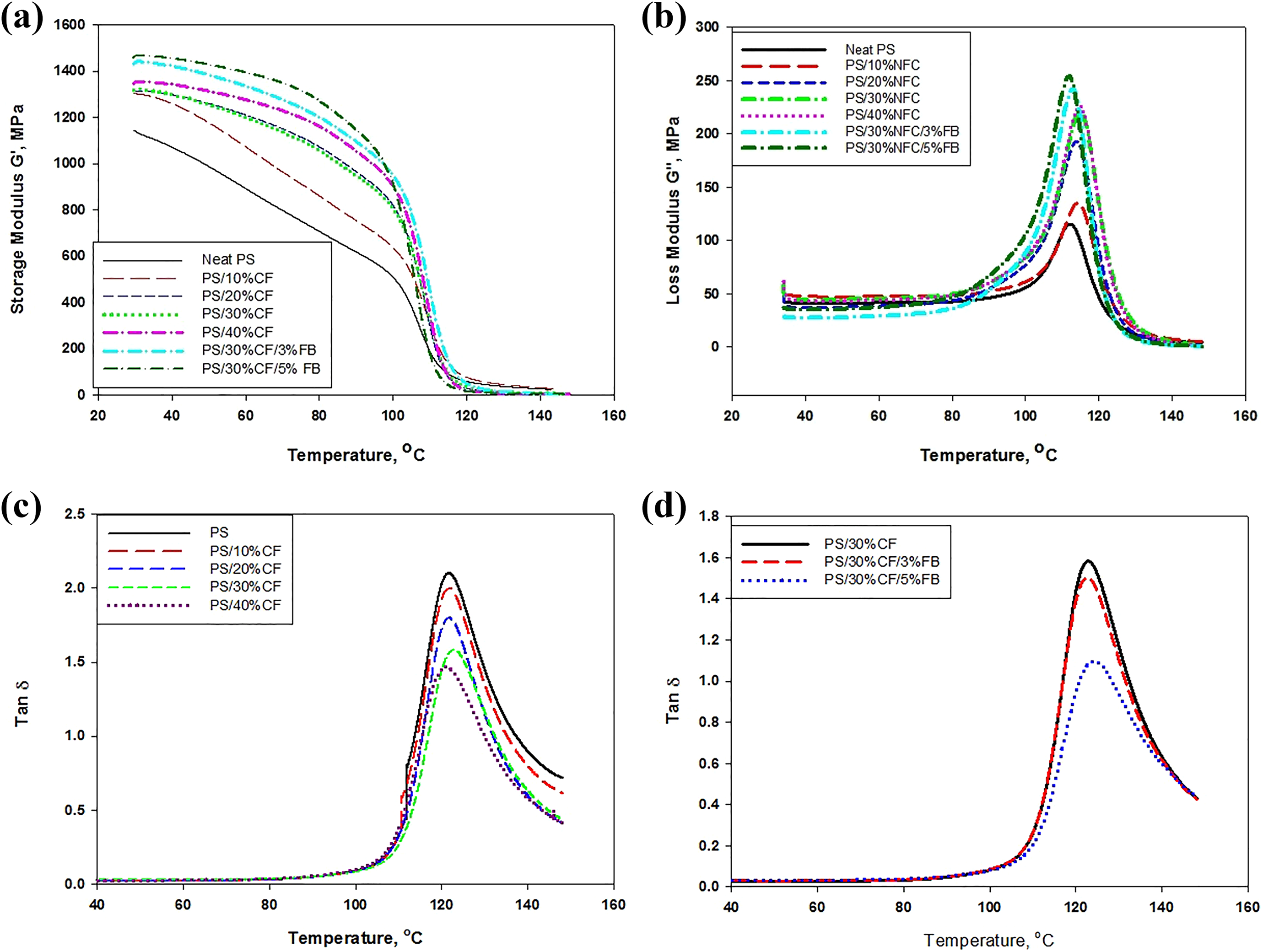
Results of the TG analysis.
TG: thermogravimetric; PS: polystyrene; CF: cellulose acetate fiber; FB: Fusabond.
The derivative thermogravimetry (DTG) curves of neat polyester and 20% CF with 3% and 5% FB is also shown in Figure 1(b) as an example. The DTG data show minor temperature dissimilarities of neat PS, PS/CF, and PS/CF/FB composite when compared to TG data. The shoulder peak appears at 330 and 370°C when CF is being added. The appearance of shoulder peaks demonstrates the dehydration of CF. The prominent DTG peak of PS/CF and PS/CF/FB appears when the maximum thermal degradation occurs at 374°C and finishes at 474°C The appearance of prominent peaks with slight variation indicates that CF and FB have minor influence on the stability of polyester. At the same time, it is being noted that the decomposition of CF and depolymerization of PS molecular chains coincides with the appearance of the prominent peaks.
The investigation of PS thermogravimetric scans in the range from 30°C to 300°C shows a weight loss of 0%. Moreover, the degradation of PS appears in the temperature range between 343°C and 462°C demonstrating a weight loss of 99.76%. This weight loss of 99.76%, as shown in Table 1, can be coincided with the thermal cracking of the hydrocarbon chains of PS. The addition of 10%CF to 40%CF presents a weight loss of 18–22%, respectively, and can be correlated with the first transition of temperature in PS/CF composites. The significant weight loss of 72–78% occurs between 377°C and 474°C with the addition of 10%, 20%, 30%, and 40% CF, as shown in Table 1. The weight loss can be linked to the second temperature transition peak, which leaves behind a residue of 2.5–3.78% of ash content. Furthermore, the main reason for the stability of CF is the presence of hydrogen bond, which makes it possible for thermal energy to be distributed equally. 21 Also, it can be witnessed that the addition of CF in the PS prevents the complete degradation of the PS matrix at a temperature of 550°C. The prevention of complete decomposition can be attributed to ash content when the fiber content is increased. In addition, it is observed that the residue content increases from 3.78% to 5.94% when FB is introduced in the PS/CF composite, as shown in Table 1. The FB has an insignificant effect on the thermal behavior of the PS/CF composite even when the ash content is in considerable quantity. The thermal decomposition temperatures and weight losses of PS, PS/NFC and PS/CF/FB composites are presented in Table 1.
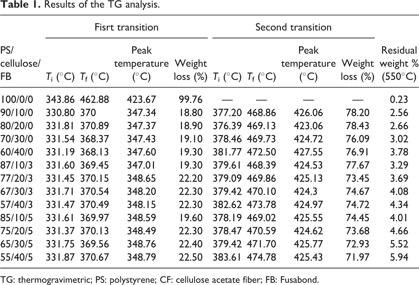
Figure 2(a) shows the value of the storage modulus (G′) of the PS/CF/FB composites as a function of temperature. The storage modulus of the PS matrix is enhanced with the inclusion of CF. The rise in modulus is due to the increase in the stiffness of the matrix because of the reinforcement facilitated by the fibers. 22,23 The sharp decline in the modulus of PS/CF composite occurs with the rise in temperature of the glass transition section. The decrease in the modulus can coincide with the molecular mobility of polymer chains above the glass transition temperature (Tg). 23 In the meantime, the outcomes show that CFs have reinforced the neat PS. This reinforcement can be noticed by studying the difference between the glassy and the rubbery state of the storage modulus G′ when compared with neat PS and PS/CF composites. The consequences of the use of the coupling agent on the storage modulus of PS/30%CF composite with 3 and 5% FB is also shown in Figure 2(a). The storage modulus is higher and increases with the increase of FB in PS/CF composite. The FB introduces the interfacial adhesion between the CF and the PS matrix, attributing to the improvement of the storage modulus of the CF/PS composite. Also, the molecular mobility in the interfacial region is reduced when FB improves the fiber matrix adhesion. The lower molecular weight of FB100D allows effective diffusion in the polymer matrix, which causes the most needed entanglement within the PS matrix. 24 The maleic anhydride in the FB introduces significant interfacial attraction because the FB forms the bonds between the hydroxyl in the CF and the maleic anhydride in FB. The improved adhesion results in the increase of storage modulus as the CF and PS matrix becomes more compatible. Moreover, the analogous behavior has been noticed with all concentrations of PS/CF composite when the FB is added. The maximum value of storage modulus is shown in Table 2.
(a) Storage modulus of PS/CF/FB, (b) loss modulus of PS/CF/FB, (c) tan δ of PS/CF, and (d) tan δ of PS/CF and PS/CF/FB.
Storage modulus, E′, tan δ, Tg, and A of PS/CF/FB.
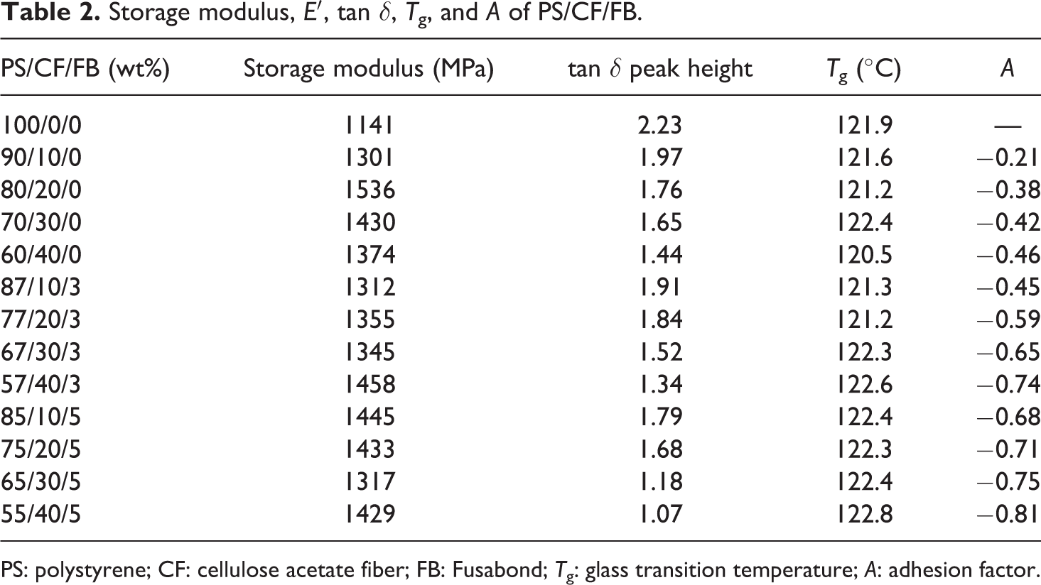
PS: polystyrene; CF: cellulose acetate fiber; FB: Fusabond; Tg: glass transition temperature; A: adhesion factor.
The loss modulus, G″, as a function of the temperature for the PS/CF composite is shown in Figure 2(b). The inclusion of CF resulted in the expansion of the G″ peak when compared to the PS matrix peak. The loss modulus curve as a result of the free movement of the polymer chains reaches a maximum value and decreases for the higher temperatures. The increase in loss modulus peak height with varying CF content is likely to have occurred due to the inhibition of the relaxation process within the PS/CF composite. The relaxation occurs due to the enhancement in the number of chain segments and the presence of free volume upon fiber addition. 25,26 Also, the decrease in the G″ decreases the internal friction which results in the increase in dissipation energy. 19 Additionally, the presence of CF adds to free mobility of polymeric molecules which helps to enhance the flexibility of composite. 23 The PS/30%CF composite with the addition of 3% and 5%FB results in the higher value of G″ is shown in Figure 2(b) as an example. The higher value of G″ is related to maleic anhydride presence in FB, which develops the bond between the PS matrix and the CF. The existence of bonds increases the height of loss modulus peak and increases the viscous response with the relaxation mechanism of the PS/CF composite.
The mechanical damping, tan δ, values of the PS/CF are lower than the neat PS, as shown in Figure 2(c). The values show that the tan δ value decreases as the concentration of CF fibers increases in the composite. The reduction in the tan δ occurs due to the restriction in movement of the PS molecules caused by the presence of stiff fiber. 27 Moreover, the improvement in the interfacial adhesion occurs due to the addition of FB, which shrinks the tan δ peak height to 1.07 of PS/CF/FB, as shown in Figure 2(d) and Table 2. The reduction in the tan δ peak increases the molecular relaxation and facilitates the PS/CF composite to absorb a higher amount of energy. The improvement in absorption behavior is being introduced because of the strong interfacial adhesion causing less dissipation of energy in the composite. The Tg values obtained from tan δ peak for the PS, PS/CF, and PS/CF/FB are presented in Table 2. The Tg values of the PS matrix show a slight variation when the CF and FB is incorporated. The variation may be attributed to the restriction imposed by the fibers on the molecular motion in the PS matrix.
The relative damping of the composite and polymer matrix can be used to estimate the adhesion factor A by considering the volume fraction of fiber as shown in equation (1): 28
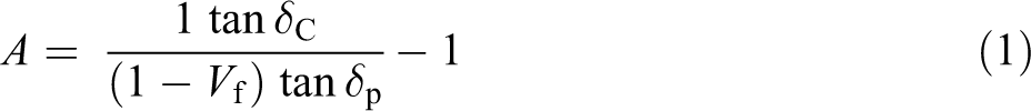
where tan δc and tan δp are the relative damping of composite and polymer and Vf is the volume fraction of the fiber. The value of A decreases with the addition of FB, as shown in Table 2. The lower level of adhesion factor A is related to the strong adhesion. The lower value of A occurs due to the reduction in tan δc. However, the decrease in tan δc happens due to the reduction in the molecular mobility in the vicinity of fiber, which enhances the interaction between the PS matrix and the CF.
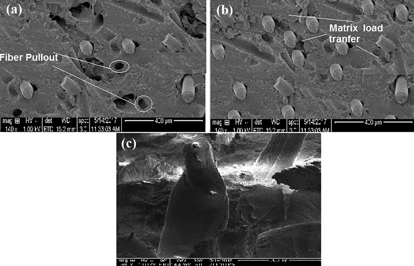
The stress (σ) and strain (ε) behavior of PS with the addition of cellulose fiber and FB are presented in Figure 3(a) and (b) with the summary of results in Table 3. The tensile strength and elastic modulus of neat PS are 17.63 MPA and 0.9 GPa. The increase of CF content increases the elastic modulus up to 20% and tensile strength up to 21% but decreases the %elongation of PS. The elastic modulus and strength gradually increase with the addition of CF content probably because of the steady enhancement of rigidity in the PS matrix, as shown in Figure 3(a) and (b). The decrease in the %elongation upto 20% with the increasing CF loading can be attributed to the rigid behavior of the PS matrix, as shown in Table 3. In addition, the FB coupling agent strongly impacts on the mechanical characteristics, as shown in Figure 3(b) and Table 3. The decline in the strength with FB in PS/CF composite is 18–25%. This characteristic might be credited to the reaction that occurs between the OH group of CF and the anhydride group of the FB. Also, the %elongation increases up to 20% with the addition of the coupling agent. The use of FB increases the dispersion of CF in the PS matrix reducing the fiber–fiber interactions. The reduced fiber–fiber interaction allows the matrix to transfer the applied stresses to the fiber. Similarly, the improvement in the interfacial adhesion enhances the stress transfer from the PS matrix to the stiffer CF increasing, in turn, the elastic modulus.
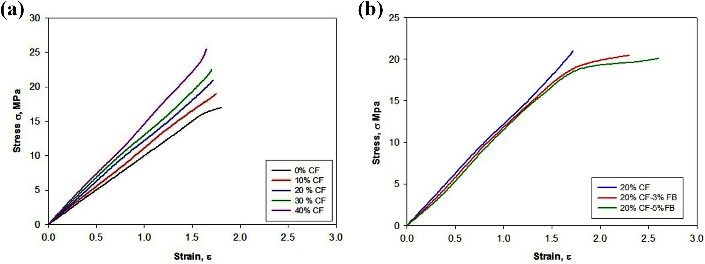
(a) Tensile behavior of PS/CF composite and (b) tensile behavior of 77% PS/20%CF/3%FB and 75%PS/20%CF/5%FB.
Mechanical properties of PS/CF/FB.
PS: polystyrene; CF: cellulose acetate fiber; FB: Fusabond.
Table 3 shows the impact strength of PS with the increasing content of CF and FB. The impact strength of neat PS is 5.69 kJ m−2. The impact strength of PS/CF composite is lower than the neat PS indicating the decline in toughness. Furthermore, Table 3 shows that the impact strength of PS/CF composite reduces up to 48%. The reduction in impact strength might be due to the stiffness of the CF that restricts the mobility of the polymer chains and also due to the poor interfacial interaction between the CF and the PS polymer. On the other hand, the rise in the impact strength has been observed up to 20–34% with the addition of FB in comparison to PS/CF composite. The improvement in the impact strength of PS/CF/FB composites occurs due to the better adhesion between polymer blends and CF bonding. The enhanced adhesion implies that the composite with the addition of FB is tougher than PS/CF under dynamic loading. The improved impact energy with the addition of FB corresponds to the reduction of tan δ peak and low value of adhesion factor A, as shown in Figure 2 and Table 2.
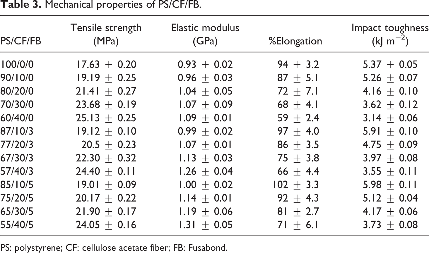
The tensile fracture surface of PS/CF (80/20) composite is shown in Figure 4. Figure 4(a) shows the CF pulled out and the voids on the surface indicating the poor interfacial adhesion between the PS matrix and the CF. Meanwhile, the fracture of PS/CF/FB (75/20/5) presents the rough and uneven surface due to load transfer from the PS matrix to the CF. Also, the decrease in the number of voids suggests the improvement in the interfacial affinity and adhesion between the CF and the PS matrix, as shown in Figure 4(b). Furthermore, Figure 4(c) shows the twist in the single fiber presenting the fracture of PS/CF/FB composite due to load transfer in the fiber. The load transfer in the fibers occurs due to the improvement in the interfacial affinity and adhesion by the addition of FB MB E 100 D as a coupling agent. The addition of FB introduces a considerable amount of compatibility between the PS and the cellulose fiber, which is being presented by the increased storage modulus and enhanced mechanical properties of the PS/CF/FB composites.
SEM micrograph of (a) fracture surface of PS/20%CF, (b) fracture surface of PS/20%CF/5%FB, and (c) fracture of single fiber in PS/20%CF/5%FB.
The XPS high-resolution scan was conducted on the C1 s and O1 s regions of the specimen to determine the types of carbon–oxygen bonds. The XPS peaks of PS, PS/CF, and PS/CF/FB with the variable intensities of the functional groups corresponding to C1 s and O1 s region are shown Figure 5. The binding energy and corresponding bond type with their atomic concentrations are shown in Table 3. The PS is formed by covalent bonding of carbon, hydrogen, and oxygen. Except for hydrogen, the C–H, C–C, C-–O–H, and C–O–C bonds are presented in the PS with their peak positions and mass% concentration, as shown in Figure 5(a) and Table 4. The addition of CF to the PS increases the concentration of carbon–oxygen bond in the PS/CF composite, as it is shown in Figure 5(b). The increase is expected since the major component of CF has a large percentage of carbon–oxygen in their chemical structure than the PS, 29 which is shown by the slight rise of atomic concentration in C–O–C=O and C–C from 0.324 at.% to 0.653 at.%. Meanwhile, the rise in C–O–C=O is observed from 0.427 mass% to 0.859 mass%. Nicole et al. 29 presented the peak of C–C to C–H at 285.0 eV, which corresponds to the bonding of the polymer matrix with the CF. The FB E MB100D (maleic anhydrides high-density polyethylene) contains C–O–H and C–O–C bonds. The C–O–H and C–O–C structure increases the graft reactivity of the carbon–oxygen bond in the polymer matrix. 30,31 The availability of the hydroxyl bond leads to a generation of an interaction between the PS matrix and the CF, which enhances the properties of composites. However, the rise in graft reactivity creates the cross-linking or strong adhesion at the interface due to the rise of shoulder peaks in C1 s region, as it is illustrated in Figure 5(c). The trend exhibits the variation in the concentration of C–O–H/C–O–C bonds from 4.326 mass% to 5.365 mass % leading to an increase in the O/C ratio, which is attributed to the addition of FB, as shown in the Table 4. Moreover, the decrease in concentrations of C–H and C–C bonds occurred from 91.598 mass % to 90.984 mass % due to the addition of FB in PS/CF composite. Nevertheless, it is assumed that the molecular chain of FB E MB 100D is shorter than PS and cellulose fibers. These shorter length molecular chains have distinct feature, which make the use of FB limited in improving the interfacial adhesion. 26 The limited improvement of PS/CF/FB composite is being confirmed by the enhancement in the impact energy and decrease in damping tan δ peak.
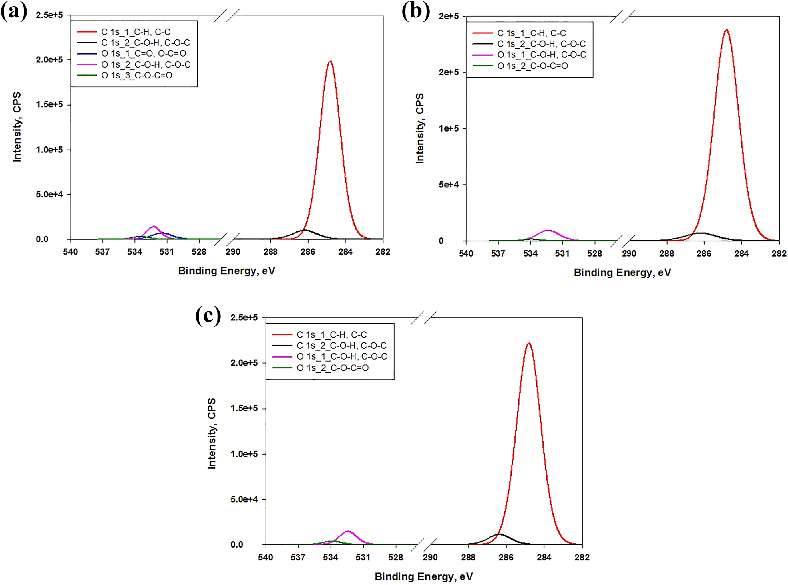
XPS peaks in C1 s and O1 s region (a) PS, (b) PS/CF composites, and (c) PS/CF/FB composite.
XPS peaks with binding energy and bond type of O1 s, C1 s, and N1 s regions with mass% concentration.
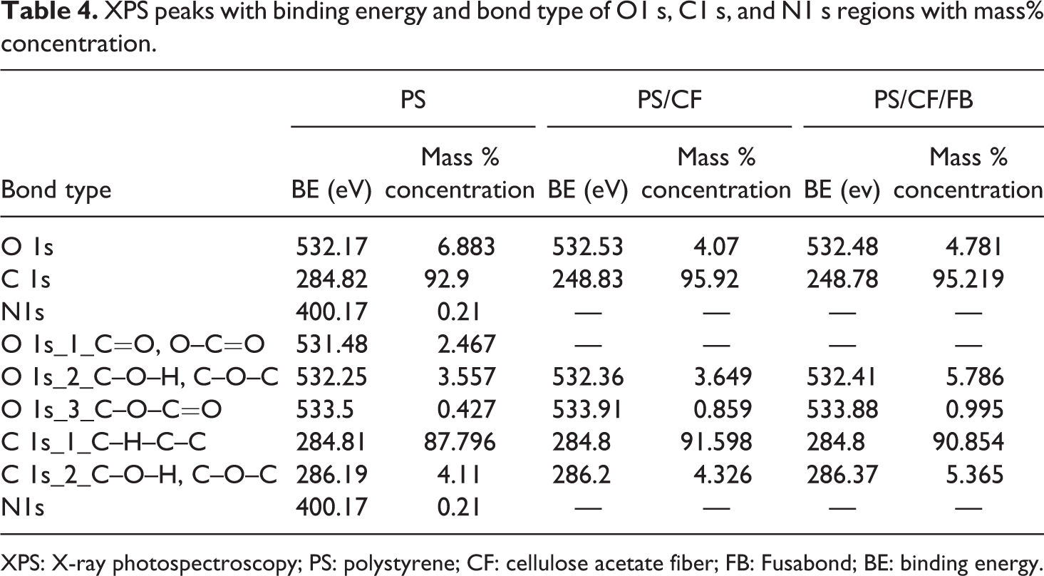
XPS: X-ray photospectroscopy; PS: polystyrene; CF: cellulose acetate fiber; FB: Fusabond; BE: binding energy.
Conclusion
The effect of FB is being successfully studied on the PS/CF composite, which was produced by the twin extruder. The TG thermograms of the PS/CF composite present the negligible effect of FB. Also, the increase in the modulus and the decrease in tan δ with the addition of FB improves the molecular relaxation of the examined PS/CF composite. The reduction in the tan δ peak increases the molecular relaxation and facilitates the PS/CF composite to absorb a higher amount of energy. Furthermore, the impact energy decreases with the incorporation of CF due to the rigidity of the fiber, which leads to insignificant interfacial strength. Meanwhile, the addition of FB in PS/CF increases the impact strength and % elongation revealing the interfacial strengthening between the PS matrix and the CF. The analysis of impact energy shows that the addition of 3% and 5% FB integrates higher impact energy, which increases the toughness of the PS/CF composite. Moreover, it was observed that the C–O–H and C–O–C bonds, which are present in FB assist in forming a conjugated structure. Finally, the interfacial adhesion between the PS and CF is confirmed by the presence of cross-linking and interfacial bonding. The PS/CF/FB composite fabricated in this study is intended to be used in the packaging, automotive, and biomedical applications.