
Abstract
The research presented in the article concerns the resistance to damage of thermosetting and thermoplastic fabric carbon composites. A comparison of these materials resistance was made on the basis of the results of residual strength tests which include impact tests and static compression of samples after impact. The impact tests consisted of two impact criteria: specimens impacted with energy adjusted to the specimen thickness, determined on the basis of ASTM D7136 (energy criterion) and specimens impacted in such a way so as to obtain a specific depth of indentation (indentation depth criterion). The specimens struck according to the indentation depth criterion were additionally divided into two subgroups: with the indentation depth of 1.3 mm and the indentation depth of 2.6 mm. In addition, after impact tests, each specimen was subjected to ultrasonic phased array testing in order to obtain information about the extent of the damage. Experimental results showed that with less impact energy, the thermoplastic laminate has a higher residual strength than the thermosetting composite. This difference decreases as the impact energy increases.
Introduction
Fibre-reinforced composite materials have seen a rapid growth in the last two decades in many branches of industry, in particular in the aviation industry. 1,2 Typical laminate composite is made of several layers of reinforcement impregnated with resin. Due to the typical variation in the reinforcement orientation and stratified structure, laminates display relatively low resistance against interlaminar fracture, and formation of delaminations, especially exposed to impact events. During these events different types of damage can occur, such as matrix cracking, fibre fracture and fibre–matrix debonding. 3,4 Low velocity impact damage can be introduced as a result of events, such as dropping tools during maintenance or due to impact of bird strike, hailstones, runway debris and so on during service. 5 An impact on a composite laminate panel may result in invisible external damage, but it may generate a dramatic reduction of compressive strength. Therefore, considerable research has been devoted to analysing the impact properties and post-impact compression behaviour with a view to improving impact energy tolerance. 6 –10 As stated in the literature, 5 1.3 mm is typical value of dent depth threshold used to quantify damage visibility during initial visually inspections of aircraft. This is the threshold named to barely detectable impact damage, which ensures that the structure will still meet ultimate strength requirements.
In the aerospace industry, one of the most widespread composites are thermosetting composites. 11 –14 However, composites with a thermoplastic matrix seem to be a promising alternative to the above. The attractiveness of thermoplastic composites in relation to thermosetting is their high resistance to dynamic loads, high chemical resistance, higher hydrophobicity, as well as the ability to work in a higher range of temperatures. Low coefficient of moisture absorption provides higher resistance to changing weather conditions. 15 In addition, despite the high price of the thermoplastics themselves, such as polyetherketone (PEK), polyetheretherketone (PEEK) and polyphenylenesulphide (PPS), the total cost of manufacturing parts is much lower as a result of a significant reduction in production time and no need for other expensive technologies. Due to these aspects, in the present investigation, these two types of composites were chosen to reflect the damage resistance. Panels for the test made of thermoset composites were manufactured in the out-of-autoclave technology. Thermoplastic composite was manually laid up and consolidated in hot pressing technology. The damage resistance properties are particularly highly dependent upon several factors, such as specimen geometry, layup, impactor geometry, impactor mass, impact force, impact energy and boundary conditions. 2,5 Therefore, the compared specimens were made of the most similar thickness and similar quasi-isotropic layer layout.
In this article, damage resistance was assessed through drop-weight impact and compression after impact (CAI) tests. 16 –23 CAI tests consisted of two stages: producing a localized damage by drop-weight event and testing residual compressive strength of the laminate. Compression tests were performed 7 days after the impact, allowing for impact-induced stress relaxation. After the impact tests, ultrasonic testing (non-destructive testing – NDT) was performed to compare post-stroke damage inside CAI specimens. As part of the residual strength tests, two groups of specimens were tested, in which impact damages were introduced in the first group according to the energy criterion (energy adjusted to the specimen thickness according to ASTM D7136 standard) and in the second group according to the dent depth criterion.
In the presented research, one of the variants of damage levels depth is the indentation with a depth of 1.3 mm. The scope of examinations was additionally increased by examination of two times deeper indentation. To determine the parameters of the impact with specific depth, a series of strokes on the calibration plate was made. The calibration panel and impacting specimens were tested at room temperature ambient conditions without prior conditioning.
Research object
Carbon-epoxy fabric laminate panels were analysed for dent calibration and rectangular plate with a dimension of 150 × 100 mm2 and the thickness resulting from the number of layers of around 5 mm. Two types of material were compared – thermoplastic and thermoset carbon fibre-reinforced composites. The number of layers was selected in such a way so as to obtain approximately identical thickness for both kinds of the tested materials. Because prepregs from thermoplastic and thermoset have different thickness, thermosetting composite consisted of 24 layers and thermoplastic of 16 layers. The following reinforcement layer configurations were considered: thermosetting composite layup [45/0/–45/90]3s and thermoplastic composite layup [45/0/–45/90]2s. CAI coupons were cut out on Computerized Numerical Control (CNC) plotter and next ground 24 to achieve roughness parameters and dimensional tolerances according to ASTM recommendations.
Energy calibration
The main purpose of the calibration was to determine the impact parameters that cause the desired dents depth. Impact energies and drop heights were sought that would generate damage of 1.3 mm and 2.6 mm in depths. The impact tests calibration was performed with the use of a drop-weight tower INSTRON CEAST 9350 equipped with an impactor weighing 5.5 kg with a spherical tip diameter of 16 mm and fixture with a clamping ring diameter of 76 mm. The picture below (Figure 1) shows the drop tower impact machine.
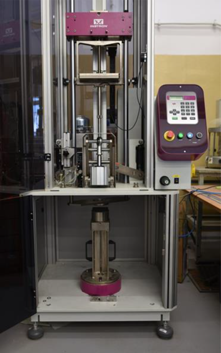
Test stand for performed drop-weight impact test.
Using this fixture in relation to the typical CAI support fixture allows to achieve more conservative results. On the calibration panels, the neighbouring impact points were 8 cm apart to avoid the effect of impact from neighbouring impact fields, but also to fit as many strike fields as possible on one panel.
The following charts (Figure 2) depict the calibration results of thermoplastic and thermoset composites with marked two desired level of dent depth (1.3 and 2.6 mm).
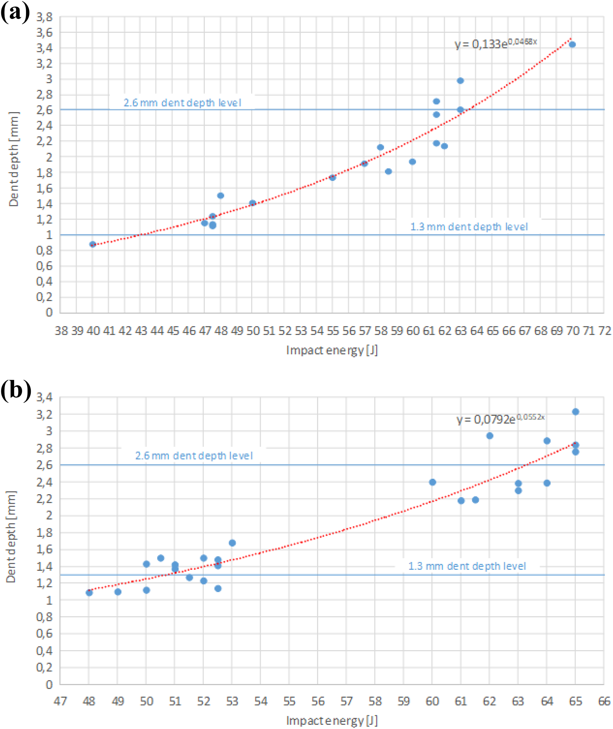
Compression impact energy versus dent depth calibration of (a) thermoplastic and (b) thermoset carbon fibre fabric-reinforced composites.
The obtained impact parameters during dent depths calibration are presented in the Table 1.
Impact parameters determined for specimens impacted according to the dent depth criterion.
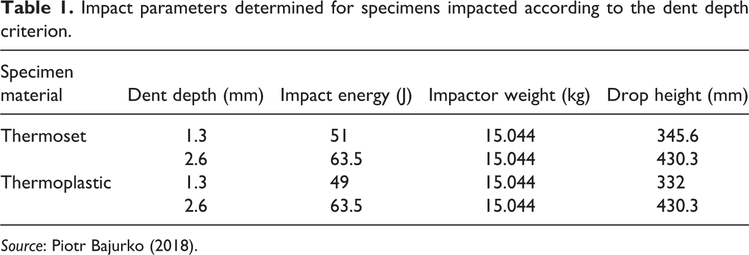
Source: Piotr Bajurko (2018).
Impact test of coupons
A flat, rectangular composite plate was subjected to out-of-plane, concentrated impact using the same drop-weight device with the hemispherical impactor as during the calibration test. The impactor was automatically arrested after rebounding to avoid the second strike. First, a group of specimens were impacted with energy adjusted to the thickness (three specimens from each material in accordance with ASTM D7136). Impact energy was calculated according to the equation

where E – impact energy, J; CE – specified ratio of impact energy to coupon thickness, 6.7 J/mm; h – nominal coupon thickness in mm.
Next, drop height was calculated according to the equation

where H – drop height of impactor, m; md – impactor weight, kg; g – gravity acceleration, 9.81 m/s2.
Table 2 represents the impact parameter calculated for thermoplastic and thermoset carbon fibre fabric-reinforced composites.
Impact parameters determined for specimens impacted according to the energy criterion.
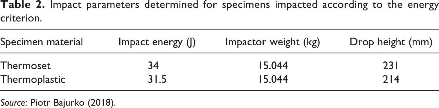
Source: Piotr Bajurko (2018).
The second group of specimens were impacted with parameters determined during calibration (Table 1) to archive intended dent depth. For each of the materials, six samples were impacted (three specimens with an indentation of 1.3 mm in depth and three specimens with an indentation of 2.6 mm in depth).
Deformation versus force relationships of thermoset and thermoplastic composite for three impact energy levels are shown in Figure 3.
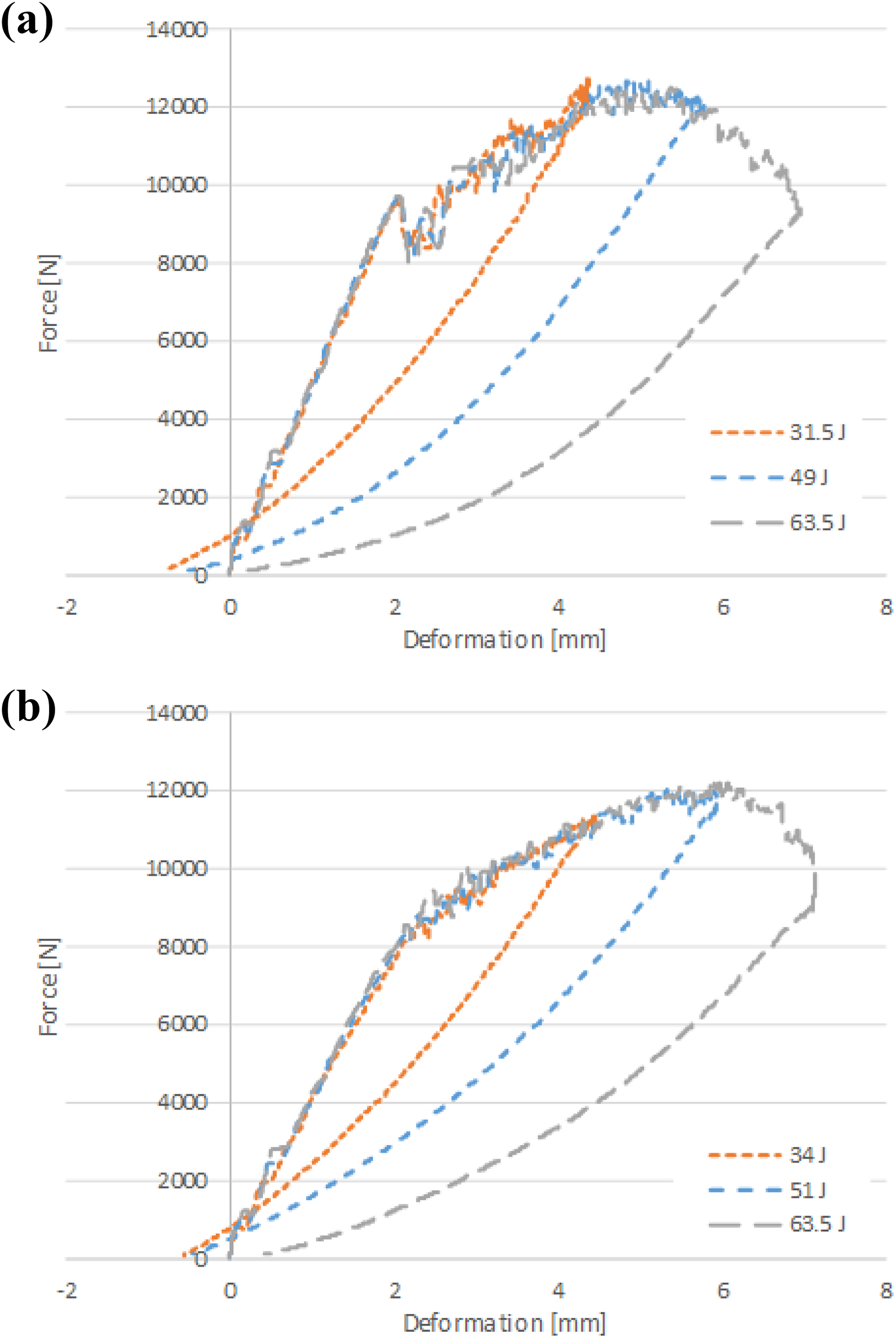
Deformation versus force (a) of thermoset composite for three impact energy level (31.5 J, 49 J and 63.5 J) and (b) of thermoplastics composite test for three impact energy level (34 J, 51 J and 63.5 J).
The initial fragments of the graph are identical regardless of the impact energy for both the thermoset (Figure 3(a)) and the thermoplastic (Figure 3(b)). The main difference between force–deformation curves of thermoplastic and thermosetting can be seen in the first part, regardless of which energy level of impact we choose. To compare this in one graph (Figure 4), curves corresponding to the middle energy value of the considered impact energy levels was chosen. Namely, these are data from strokes with energy of 49 J (thermoset) and 51 J (thermoplastics). The results of only two samples from different materials were compared so as not to obscure the result in the graph.
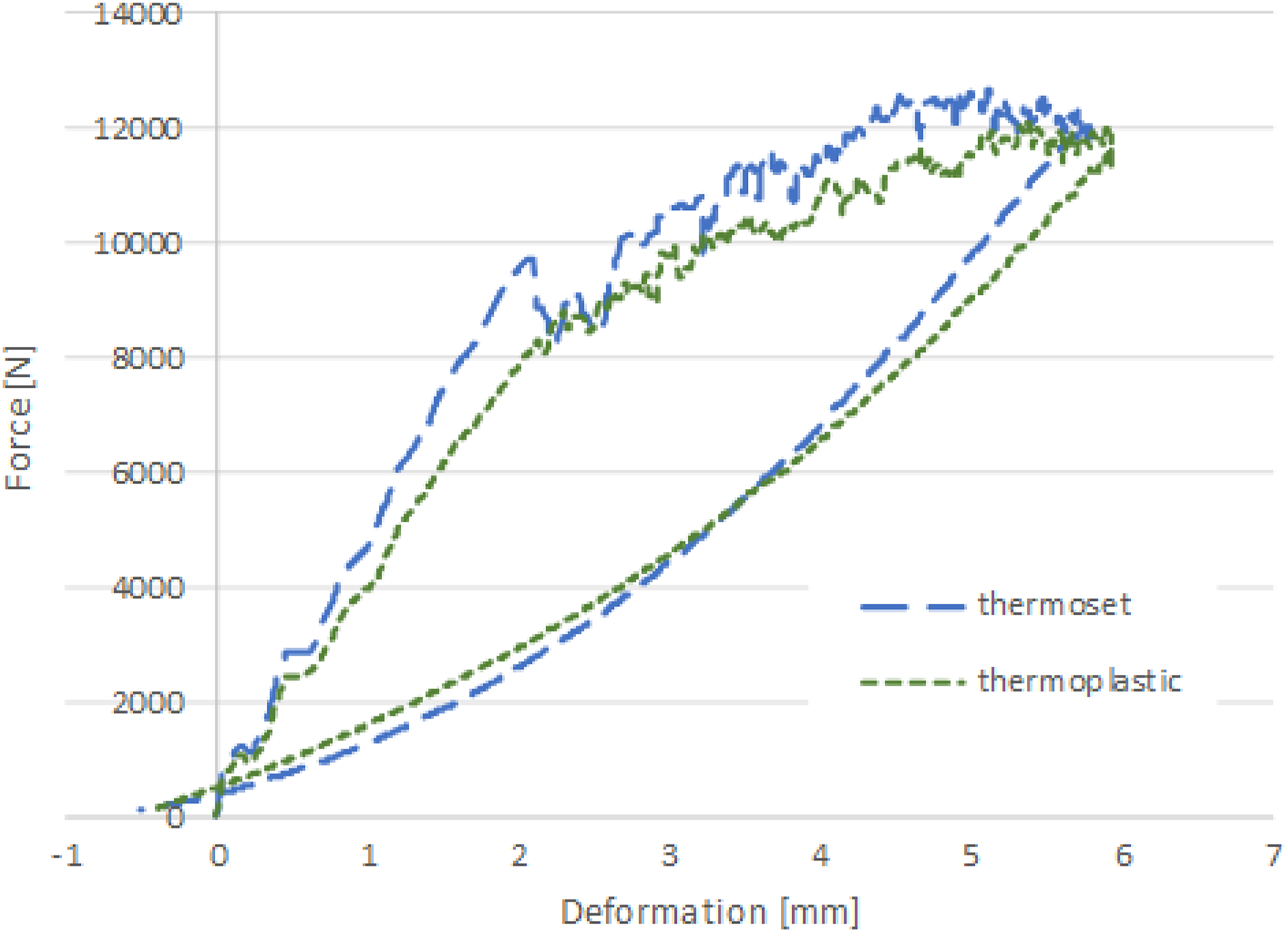
Comparison of force–deformation curve of thermoset and thermoplastic composite.
This picture shows that thermoset composite is stiffer than thermoplastic before the first damage occurred.
Post-impact C-scan
The non-destructive inspection (NDI) testing was done in order to determine the size of the damage zone. NDI tests were performed by the phased array method for each dented coupons. Ultrasonic tests were conducted using Olympus OmniScan MX defectoscope with 5 MHz phased array probe. Each scan was performed with sound velocity (2700.0 m/s) and voltage (45 V). Exemplary C-scans and B-scans of thermoplastic and thermoset from specimens impacted with energy adjusted to the thickness shown in Figure 5.
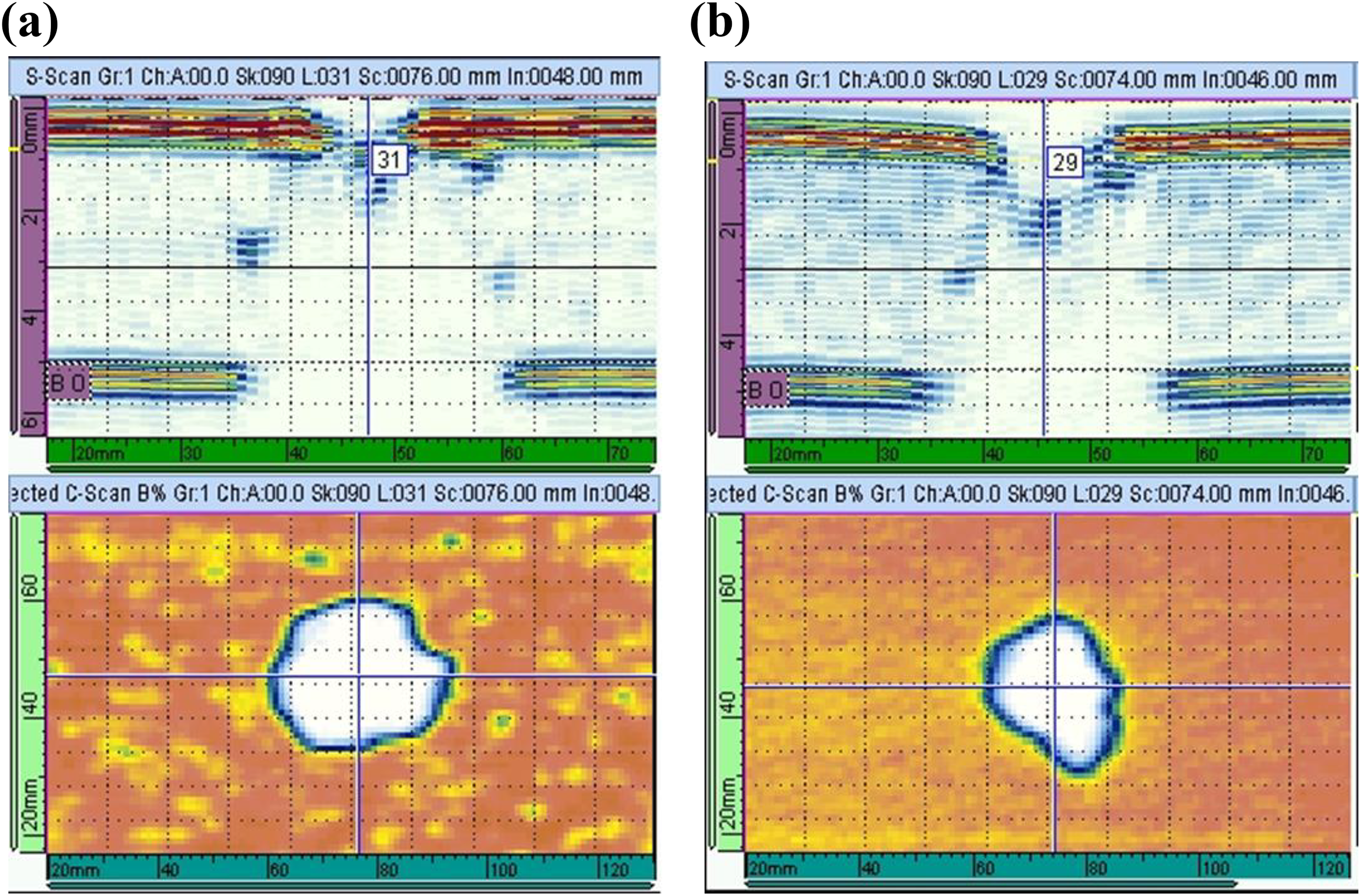
B-scan and C-scan of (a) thermoset and (b) thermoplastic.
Observing the B-scans, it can be inferred that both materials have almost identical character of external damage. It means that both damages are characterized by a similar conical shape, typical for composite plate after low energy impact loading. Additionally, no visible delamination was found in both tested composites. Clearly, delaminations can be inside the mentioned cone, but they are not detectable by this ultrasonic technique. Fabrics are less susceptible to the formation of interdigital delamination than, for instance, composites with unidirectional reinforcement. 25 Therefore, it is more difficult to observe differences in damage between fabric materials.
The damage resistance is quantified in terms of the resulting size and type of damage in the specimen. According to ASTM D7136 standard, one of the methods to determine geometric dimensions for the detected damage is measuring the maximum damage diameter. Alternatively, the parameter proposed by the standard for determining the size of damage is two-dimensional damage area from digital NDT data. The relationships between impact damage area versus impact energy and impact damage maximum diameter versus impact energy are shown in Figure 6.
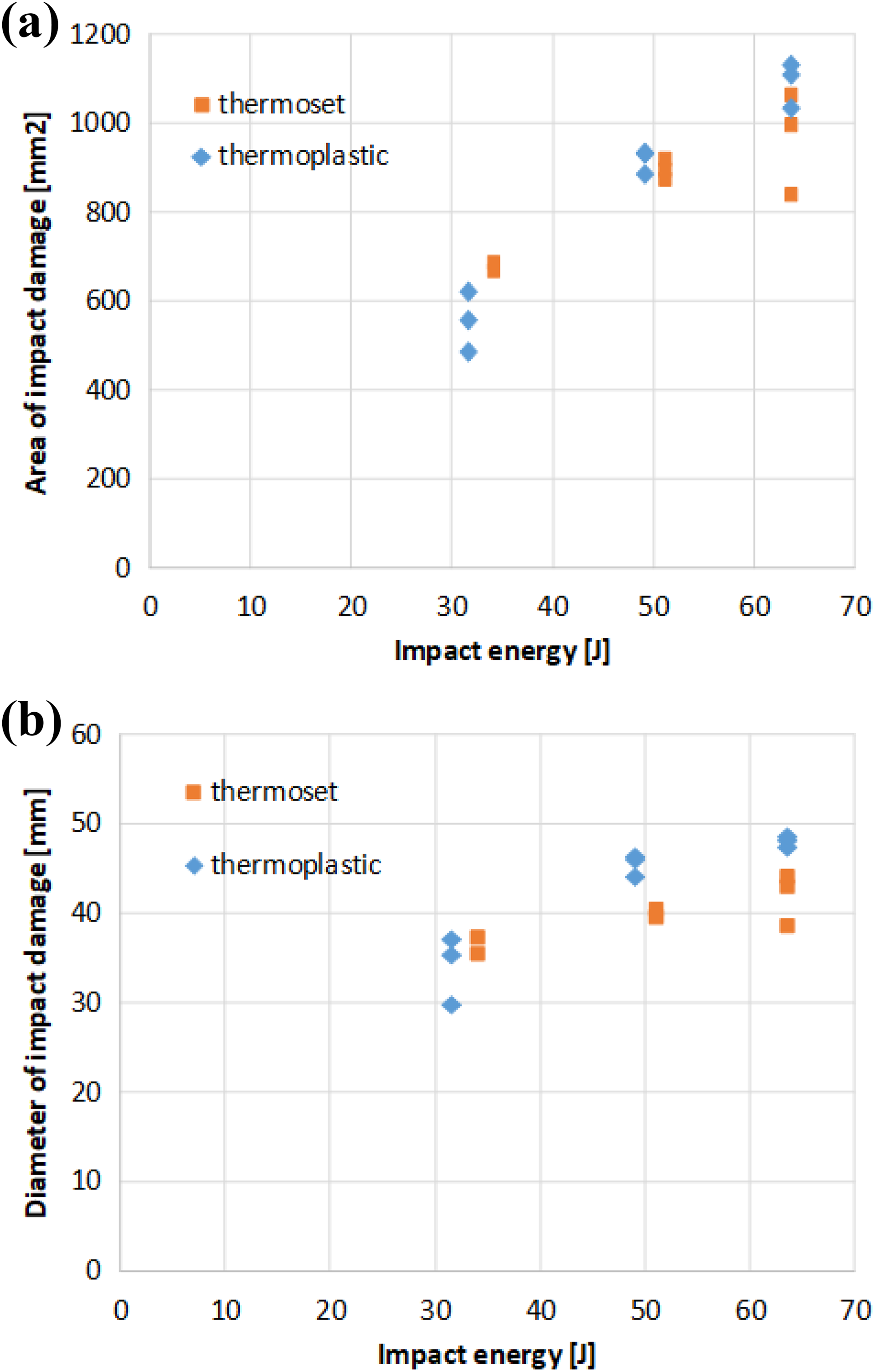
Relationships between (a) impact damage area versus impact energy and (b) impact damage maximum diameter versus impact energy.
Measuring the diameter and area of impact damage with C-scan method revealed that for both of them slight differences between thermoset and thermoplastic composites occurred. The differences increase for higher impact energy and greater damage occurs in thermoplastic material.
CAI test
The picture below (Figure 7) shows the fixture for testing the residual strength of the specimens after impact.
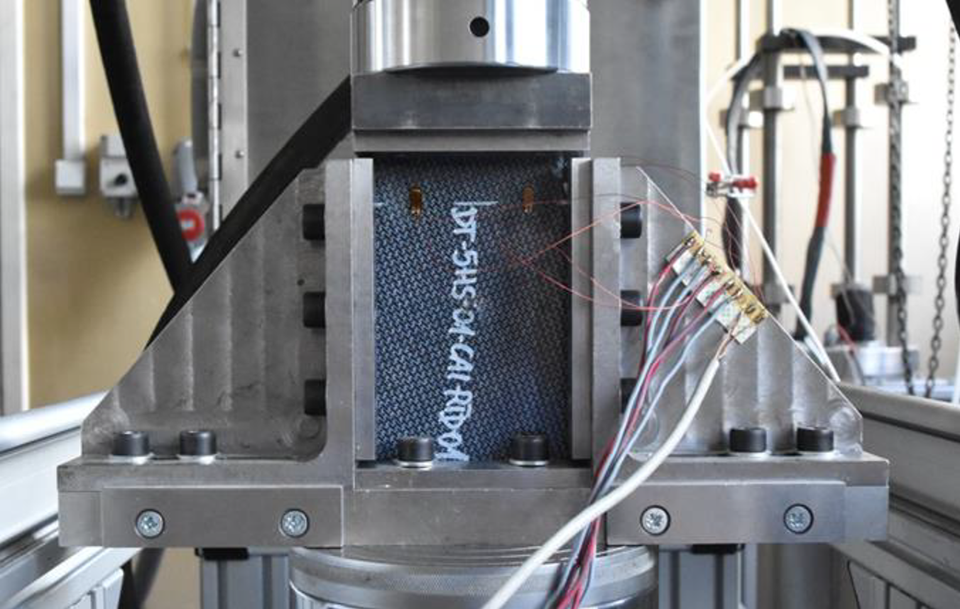
Test stand for testing residual strength after impact.
CAI test method determines the damage resistance of fabric composite laminated plates subjected to a drop-weight impact event. Samples were instrumented with back-to-back gage locations for determine percent bending during compression loading. After that, the damaged plate was installed in a multi-piece support fixture that was aligned to minimize loading eccentricities and induced specimen bending (Figure 7). Finally, the specimen/fixture assembly was placed between flat platens and end-loaded under compressive force until failure. The compressive test was run under displacement control at 1.3 mm/min crosshead speed with the use of MTS322 testing machine and Controller Flextest 40 equipped with load cell calibrated for 250 kN.
The applied force, crosshead displacement and strain data were recorded while loading with 10 Hz sampling frequency. All CAI specimens were damaged with the same failure mode Lateral through Damage in the Middle of specimen. (LDM). Diagrams in Figure 8 represent relationships between CAI strength and impact energy.
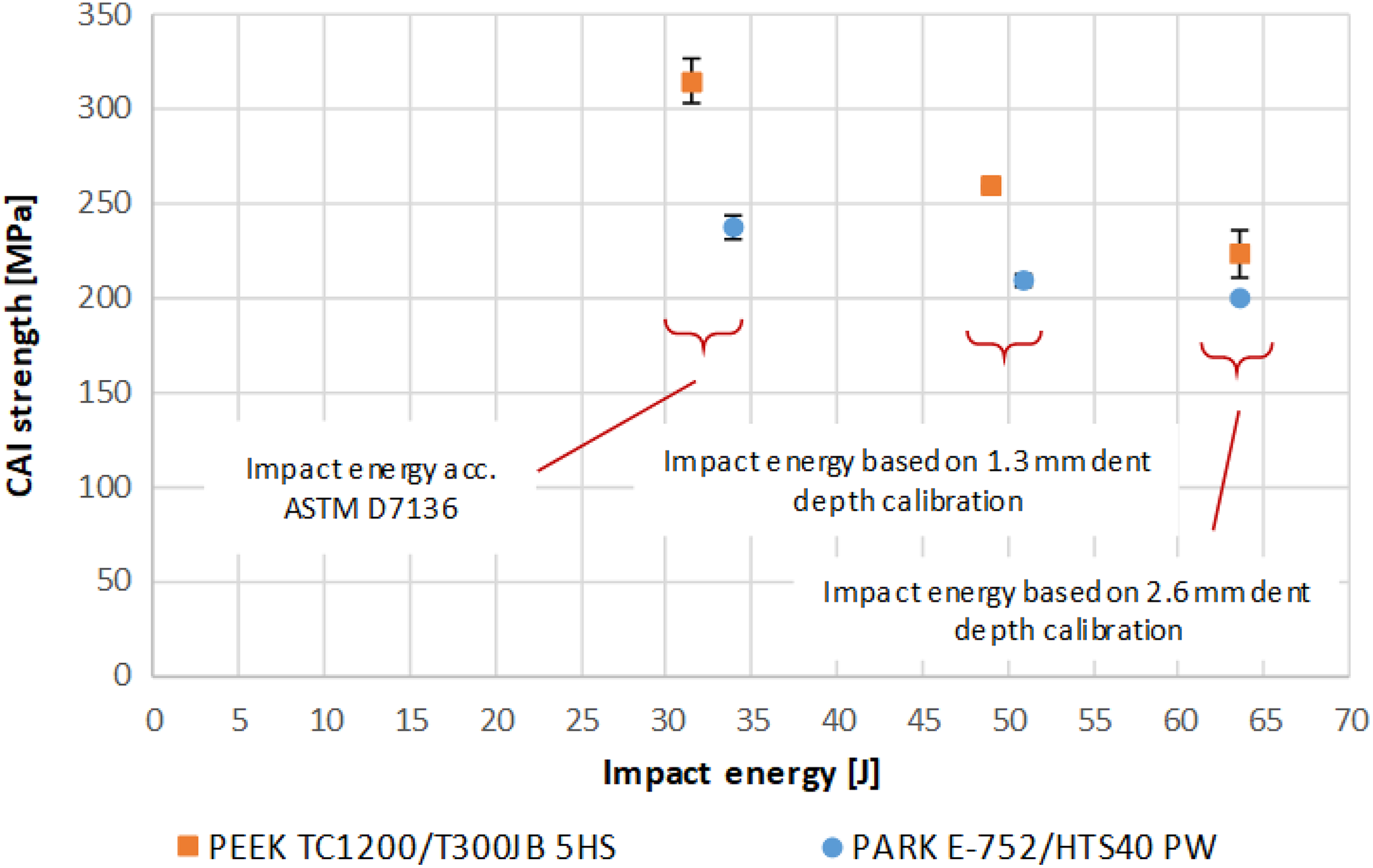
CAI strength versus impact energy for thermoplastic and thermoset composite.
In Figure 9, the CAI strength is drawn as a function of dent depth.
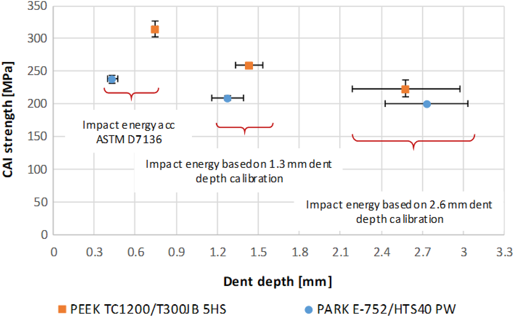
CAI strength versus dent depth for thermoplastic and thermoset composite.
Conclusions
The results of the tests allow for the following conclusions to be drawn: From the force–deformation dependence graphs (Figures 3 and 4), it appears that thermoset composite is stiffer than thermoplastics before the first damage occurs. The diagram of thermoset clearly shows the first stage of damage while the nature of the thermoplastic curve is smoother and less pointed. Based on the B-scan of coupons after impact (Figure 5), it can be concluded that both materials had almost identical nature of damage and no delamination was detected in both tested composites. Measuring the diameter and area of impact damage with C-scan method revealed that for both of them slight differences between thermoset and thermoplastic composites occurred. The differences increased for higher impact energy and greater damage occurred in thermoplastic material. Experimental results show that for smaller impact energy, the thermoplastic laminate has greater compressive strength than the thermosets composite. With the increase of energy, the difference diminishes. It can be observed from the graphs (Figures 8 and 9) that CAI Strength of thermoplastic is 27%, 8.8%, 6.8% higher than thermoset for approximately30, approximately50, approximately63 J, respectively. Horizontal error bars of CAI strength versus dent depth chart (Figure 9) show that the bigger dent depth the bigger dispersion of results was obtained. The same conclusion can be drawn from calibration test results (Figure 2). All CAI specimens were damaged with the same failure mode lateral through damage in the middle of specimen. Based on the conducted CAI tests, it is difficult to clearly state the reasons for better results of the thermoplastic composites because even the literature states that many factors can affect residual strength.
2,5,26
However, it can be presumed that this is due to the larger modulus of elasticity of the fibres used in the thermoplastic prepreg.