
Abstract
In this article, the effect of carbon nanotube’s (CNT) surface modification on mechanical, thermal, and morphological properties of nanocomposite with different content of CNTs was studied. CNT/high-density polyethylene (HDPE) nanocomposites were prepared by a mini twin-screw extruder. To modify the dispersion of MWCNTs in HDPE, the surface of CNTs was functionalized by HNO3 and stearic acid (SA). The tensile tests results show that addition of 5% of acid-treated CNT in HDPE cause to increase in Young’s modulus and yield strength up to 4% and 6%, respectively; as compared to unmodified CNT/HDPE nanocomposite. The presence of the SA on CNTs can lead to slight decrease of the CNT-SA/HDPE strength properties; when compared to pure CNT/PE nanocomposite. However, there is a fracture toughness enhancement in CNT-SA/HDPE up to 10% compare to unmodified CNT/PE nanocomposite. Furthermore, the calculation of the stress whitening zone of all samples verifies the fracture toughness data of CNT/HDPE nanocomposites. Scanning electron microscopic images showed that the best dispersion of CNTs in the HDPE matrix was seen in CNT-SA/HDPE nanocomposite.
Keywords
Introduction
Polyethylene (PE) is one of the most widely used semicrystalline polymers in the industry, due to its advantages such as low cost, high chemical resistance, high impact energy, and also good process ability. However, the application of PE in the industry has been limited regarding its low strength, poor electrical properties, and lack of rigidity. The quality of this engineering material could be improved via incorporation of a secondary phase, which could have a significant economic impact on the extending application range of PE. 1 –3
Carbon nanotube (CNT), carbon fiber, graphene oxide, bentonite, and calcium carbonate can be applied as the secondary phases in PE matrix resulting in improvement in its thermal stability, wettability, tribological, thermal degradation, mechanical, and conductive properties. 4 –7
Unique properties of CNTs such as their good thermal and electrical conductivity, excellent mechanical properties, and low density have made them an ideal choice for secondary phase in polymer matrix composites. 8 –10 However, high surface energy and aspect ratio, strong van der Waals force, and π–π interaction between CNTs result in their agglomeration, which could lead to inhomogeneous distribution of CNTs in polymer composite. Therefore, improvement of CNT’s distribution in polymers can increase the mechanical properties and electrical conductivity of composites. 11,12
Researchers studied different methods to improve the dispersion of CNTs in polymer such as ball mixing, calendaring, extrusion, solution mixing, surface modification of CNTs, and in situ polymerization methods. 13 Among them it has been shown that one of the effective methods for good distribution of CNTs in polymer is surface modification. 14 –18
Not only the dispersity of CNT in polymer can affect the properties of CNT/PE nanocomposite, but also the strong interfacial interaction between CNT and polymer can play an important role. 19,20 As surface smoothness and insignificant reactivity of CNTs with matrix, weak interfacial adhesion between polymer-CNT may usually occur. 21 In some cases, the addition of purified CNT to polymer could result in adverse effects on the mechanical properties of matrix. For instance, the presence of 1.5% CNT in PE will lead to a 40% drop in the fracture toughness of PE. 22 McNally et al. showed that the addition of pristine MWNTs to PE matrix caused a significant decrease in fracture toughness. The reason of this effect is related to the weak interfacial interaction between PE and CNT. 23 The effects of different CNTs surface treatments on the mechanical properties of polymer composites were examined. 24 –27 For example, Amr et al. showed that the incorporation of 0.5 wt% of CNT-COOH to polystyrene via thermal bulk polymerization resulted in a 22% increment in Young’s modulus. 28 The addition of diamine-MWCNTs increased the strength and modulus of diamine-MWCNT/PET composite. 29 Kanbur and Tayfun showed that the addition of CNT in polyurethane with the loading from 0.5 wt% to 2 wt% causes to enhance in tensile strength, percentage of elongation at break, and tensile modulus values of polyurethane. 30
Some studies showed that the use of polymer-grafted CNTs instead of pure CNT could result in better CNT dispersion and improve its interaction with polymer. For this purpose, Yang et al. investigated the effect of PE-g-CNTs on the mechanical properties of PE-g-CNTs/PE composite. They observed that the incorporation of 1.5 w% of CNT in composite improved its Young’s modulus, tensile strength, and fracture toughness by 53%, 50%, and 130%, respectively. 31 The effect of dendrimer coated MWCNTs (DMWCNT) on the mechanical properties of unsaturated polyester (UPR) nanocomposites was investigated by Alam et al. 32 They showed that the surface treatment of MWCNTs cause to improve the brittleness of UPR as compared to pure MWCNT/UPR nanocomposite. Besides, the stiffness and flexural strength of DMWCNT/UPR nanocomposite improved.
Good miscibility between PEO and phenoxy, decrease in the spherulite size of PEO in phenoxy-g-MWNTs/PEO composite were concluded to be the result of good MWNTs dispersion and improvement in the mechanical properties of treated MWCNTs composite in comparison to application of pure MWCNTs in composite. 33 Wei et al. showed that that short connection of n-alkyl groups to MWCNTs is easier than a long-chain polymer and leads to enhancement of PE composite’s mechanical properties. 31 The presence of stearic acid (SA)-treated MWCNTs also leads to improvement of fracture toughness and strength parameters. 34
Comprehensive studies have addressed the effect of SA or other fatty acid treatments of particles in polymer matrix composites on mechanical, thermal properties of particulate polymer composite. The results showed that SA or other fatty acids treatments could be a good method to find out the uniform dispersion of particles and suitable adhesion between secondary phase and matrix. But there is no other article that is focused on the role of SA treatment of CNTs on dispersion and mechanical properties of CNT/polymer nanocomposite. Therefore, the main aim of this study was to evaluate the effect of MWNT-SA treatment on the mechanical properties of HDPE. Besides, acid treatment is the usual method for surface treatment of CNTs which was selected to compare with SA treatment. For this purpose, three-point bending and tensile tests were carried out for pure HDPE and all nanocomposites. Moreover, the stress whitening zone (SWZ) of all samples was calculated to verify the results of three-point bending test.
Experiment
Materials
In this article, MWNTs with the external diameter of 20–60 nm, length of 5–15 μm, and purity greater than 95%, obtained from Nanolin, China as a secondary phase were used. The high-density polyethylene (HDPE) with trademark ELTEX® B4020 from INEOS England was selected as a matrix of nanocomposite. Concentrated HNO3 (68%), SA, acetone, hexane, and chloroform were supplied by Merck.
Sample preparation
Acid treatment and SA treatment
Surface modification of CNTs was carried out by acid treatment and functionalization by SA which is similar to that reported by Sahebian et al. 35,36
MWNTs (0.1 g) were dispersed in 50 ml concentrated HNO3 (68 wt%), the mixture was sonicated in a water bath for 2 h at ambient temperature, then was stirred at the same temperature for 2 h. After wards, the mixture was filtered and washed by deionized water for several times until no acid on the sample was detected or until Ph. adjusted at 6. Opened MWNTs were dried at 90°C overnight.
The oxidized CNTs were mixed in acetone for 60 min using ultrasonic bath. Some SA powder was added to acetone and stirred at 80°C. The solution including SA was added to MWCNTs media and was stirred at 80°C for 4 h. The reaction mixture was cooled to room temperature and extracted with chloroform. In order to remove residual SA, the resulting MWCNTs were further rinsed with hexane or cyclohexane. After filtering and washing with acetone, the samples were dried at 80°C in a vacuum oven overnight.
Preparation of MWCNT/HDPE nanocomposites
The PE nanocomposites were prepared by melt extrusion using the MiniLab II HAAKE Rheomex CTW5 conical twin extruder (Thermo Scientific HAAKE GmbH, Karlsruhe, Germany), after extrusion the molten materials were transferred to the HAAKE MiniJet II mini injection molder (Thermo Scientific HAAKE GmbH, Karlsruhe, Germany) to obtain ASTM D638 V dog-bone tensile bar. Pure and composites of HDPE powders were dried at 90°C in a vacuum oven for 4 h before the extrusion process. HDPE was blended with 1, 2, 5 wt% MWCNTs using a HAAKE mini twin-screw extruder at a barrel temperature of 190°C and a screw speed of 90 r/min with the cycle time of 1 min. Injection molding was done at injection process of 700 bar, cycle time of 30 s, and temperature of mold and barrel 30°C and 190°C, respectively. Table 1 shows the characteristics of PE and its nanocomposites.
Characteristics of HDPE/MWCNT nanocomposites.
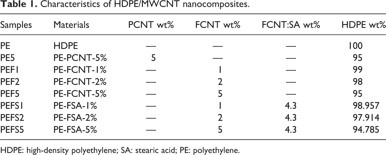
HDPE: high-density polyethylene; SA: stearic acid; PE: polyethylene.
Characterizations
Tensile testing of HDPE nanocomposites
Tensile test was done at a strain rate of 10 mm/min and ambient temperature following ASTM638. 37
Three-point bending test
Three-point bending test was done following ASTM D5045 38 at a speed of 0.5 mm/min at ambient temperature.
Scanning electron microscopy
A cold surgical blade was used to create a sharp sample notch. Besides, the deformed surface of samples was investigated and photographed by stereomicroscope Olympus LG-PS2. Scanning electron microscopy (SEM; JEOL JSM-5600 LV Ltd, Japan) was employed to evaluate the fracture surface of samples, which were covered by a thin layer of gold.
Differential scanning calorimetry (DSC)
Differential scanning calorimetry (DSC60-Shimadzu) analysis was done to determine the crystallinity of HDPE and its nanocomposites that were heated up to 200°C with speed 10°C/min and then cooled down to ambient temperature and then reheated with speed 10°C/min.
Results and discussion
Figure 1 shows that the SEM images of cryo-fractured surface of HDPE and its nanocomposites. As seen in Figure 1(a), a considerable deformation and fibrillation of HDPE on fracture surface have been prevented due to freezing HDPE by liquid nitrogen. The fracture surface of PE5 sample (Figure 1(a)) confirms the heterogeneous distribution of CNTs, some big agglomerated zone, crazing and pullout of CNTs. These attribute to the strong attraction force between nanotubes, lack of suitable interaction, and difference in elastic parameters between CNTs and HDPE.
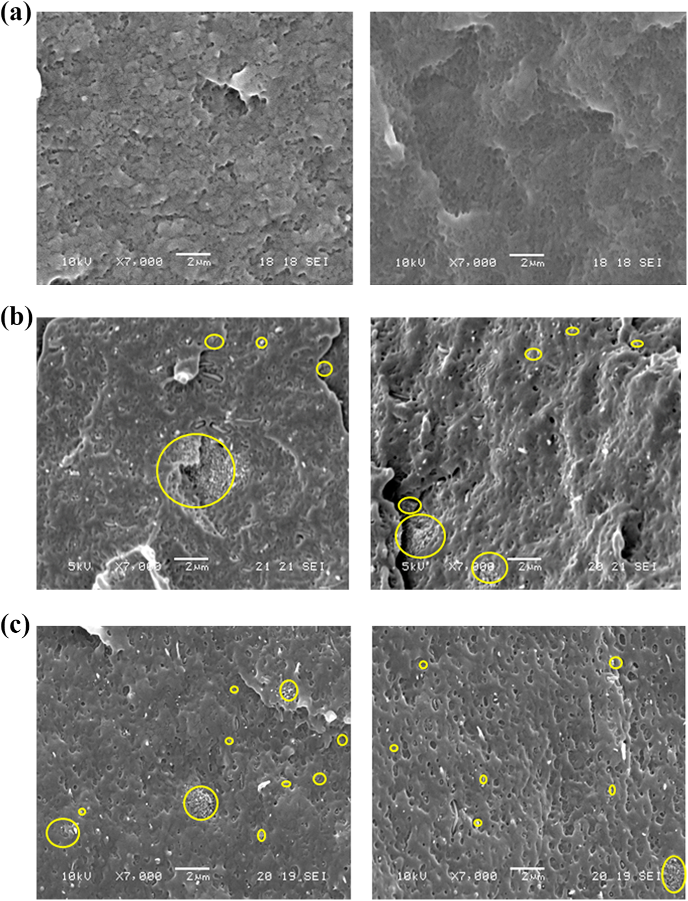
Scanning electron microscopy taken from cryo-fractured surface of (a) HDPE, (b) PE5, (c) PEF5, (d) PEFS5, and (e) PEFS5 at different magnification.
Surface modification of CNTs via acid treatment can improve their dispersity and reduce the agglomeration size of CNTs as compared to PE5.
Uniform dispersion and decrease in bundle size of CNTs can be observed in PEFS5 nanocomposite. This phenomenon can be attributed to the reduction of polarity difference and enhancement of compatibility between PE and CNTs as shown in Figure 1(e), depicting the coverage of CNT with PE in fracture surface of PEFS5.
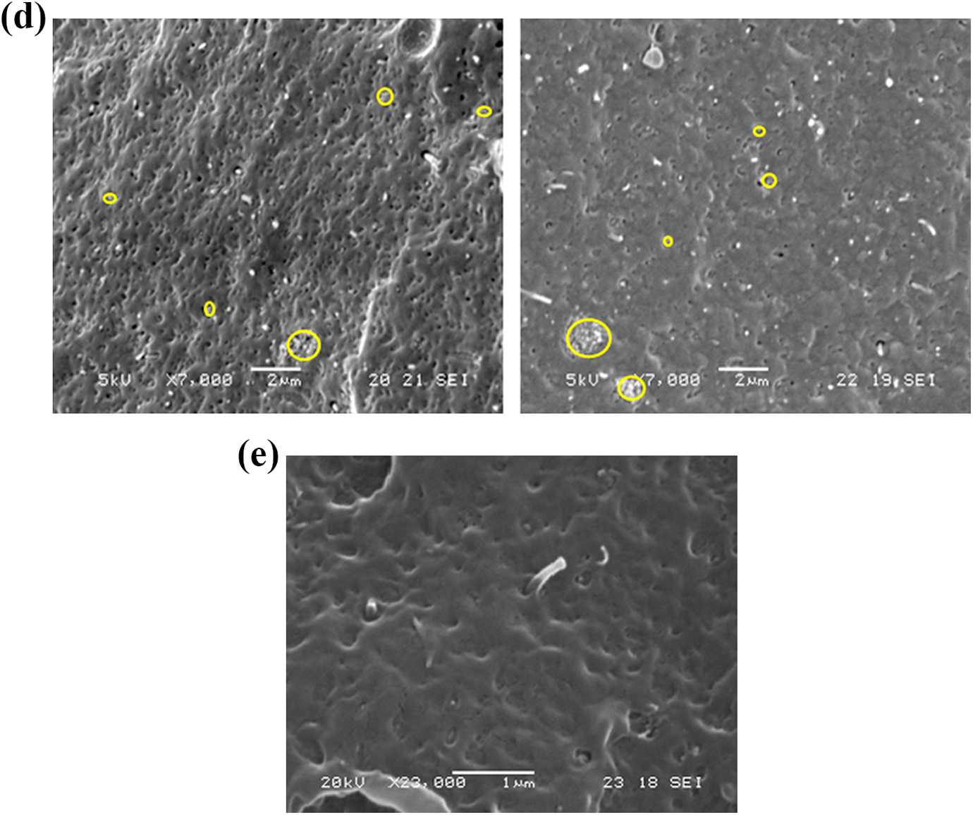
For precise comparison of CNT’s dispersity and estimating its average agglomeration size in PE5, PEF5, and PEFS5 nanocomposites, eight micrographs were randomly taken from the fracture surface of each nanocomposite. Then, the surface of agglomerated zones was calculated and divided by total fracture surface of each sample. Finally, the results are presented in Figure 2 which confirms Figure 1, functionalized CNTs cause to reduce CNT’s agglomeration and increase in interface between HDPE and CNTs.
Agglomerate area percentage in PE5, PEF5, and PEFS5.
Thermal analysis
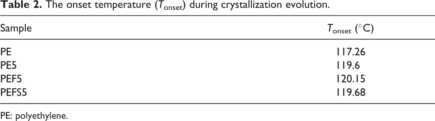
Thermal properties of PE and its nanocomposites were evaluated by DSC analysis. Cooling cycle of PE, PE5, PEF5, and PEFS5 is depicted in Figure 3. Besides, the T onset data for all samples are given in Table 2. As it can be seen, the onset temperature of crystallization increases the presence of CNTs reflecting the effect of CNTs as a suitable site for HDPE nucleation. 39,40 In comparison to PE5, the nucleation effect of CNTs is more evident in PEF5 sample owing to better distribution of MWCNTs in matrix, which will result in increase of polymer chains rigidity. SA decoration on the surface of CNTs improved the flexibility of polymer chains and also caused uniform distribution of CNTs in matrix, which could be due to the reduction of T onset for PEFS5 as compared to PEF5 nanocomposite.
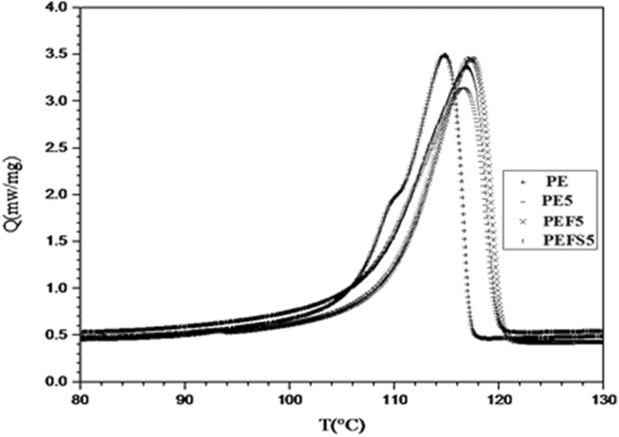
Power versus temperature of PE and its composites during crystallization evolution.
The onset temperature (T onset) during crystallization evolution.
PE: polyethylene.
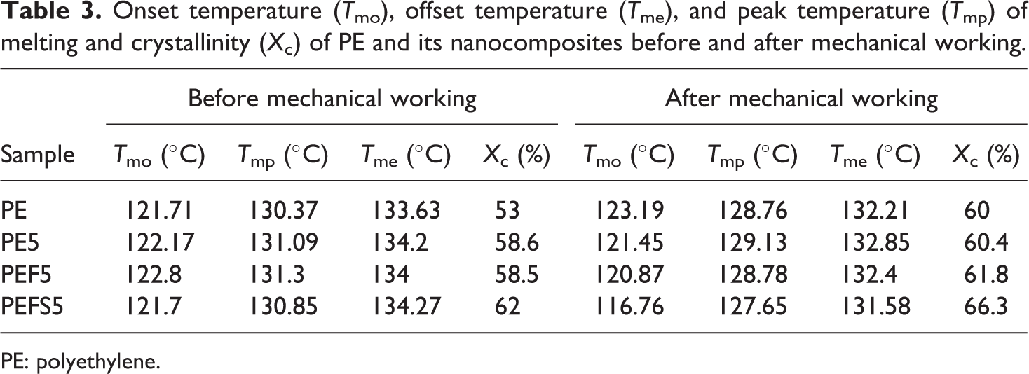
Figure 4 shows the heating cycle of PE, PE5, PEF5, and PEFS5 samples before and after three-point bending test. The crystallinity (X c), onset temperature (T mo), peak temperature (T mp), and offset temperature (T me) of each sample are also given in Table 3.
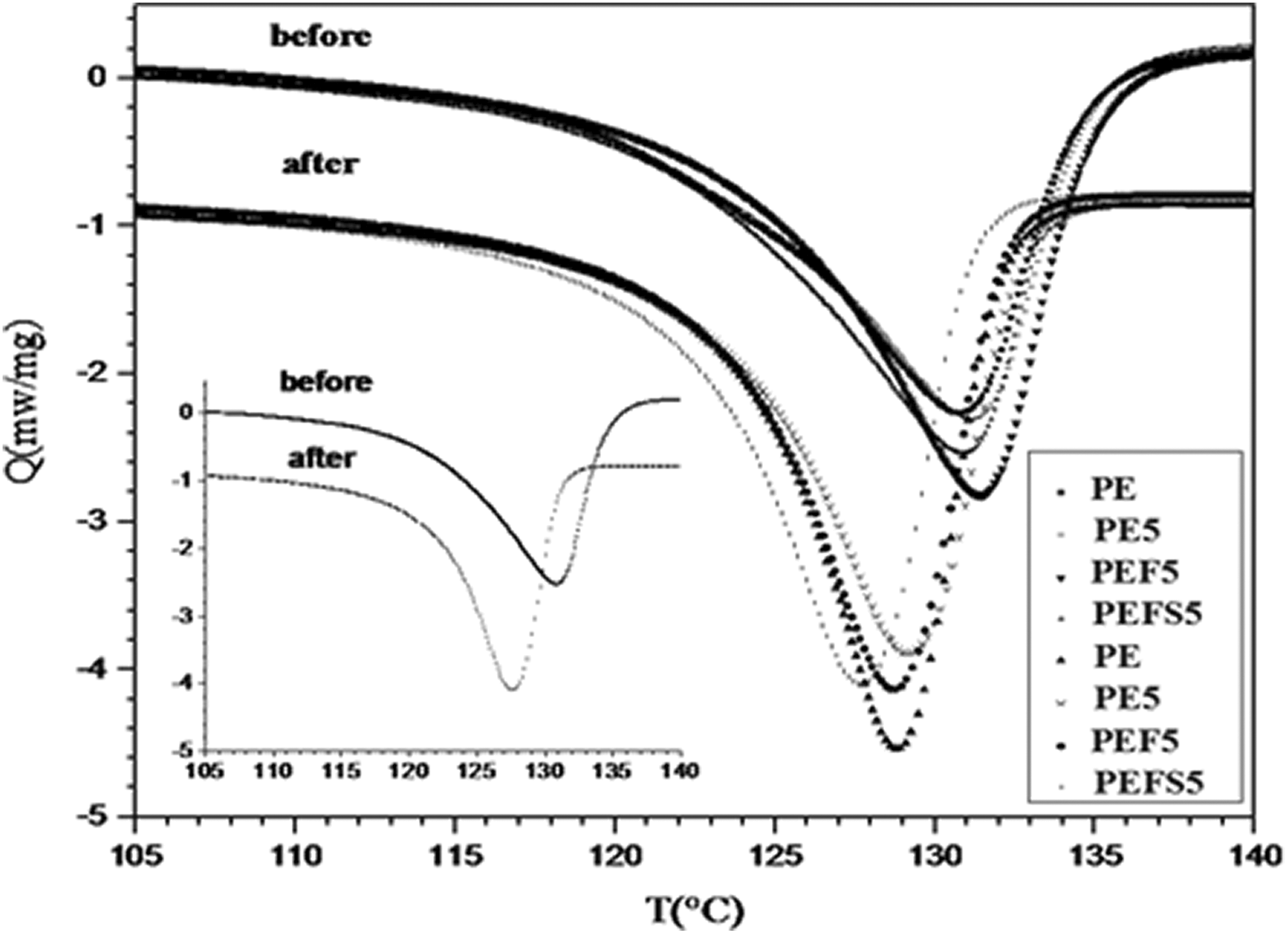
Changes in power at different temperatures during the melting process of polyethylene nanocomposites before and after mechanical working.
Onset temperature (T mo), offset temperature (T me), and peak temperature (T mp) of melting and crystallinity (X c) of PE and its nanocomposites before and after mechanical working.
PE: polyethylene.
The crystallinity degree of pure PE and its nanocomposites can be calculated using equation (1)

where ΔH and ΔH 0 are fusion enthalpy of HDPE and enthalpy of 100% crystalline PE, respectively, which are taken to be 70 cal/g. 41 According to Table 3, before mechanical working, the crystallinity of all composites was more than pure HDPE, which can be attributed the nucleation effect of MWCNTs in HDPE matrix, 42 although some researchers didn’t observe the increase in crystallization value in MWCNT/PE nanocomposites. 23,31
The uniform distribution of CNTs in matrix, enhancement of the nucleating effect of CNTs in HDPE as the result of an increase in the number of CNTs neighbor to HDPE chains, and more convenient conformation of polymer chains are the main reasons for the maximum crystallinity value of PEFS5 as compared to the other composites.
As seen in Figure 4, before mechanical working, the presence of CNTs didn’t have significant effect on the fusion temperature of HDPE. However, after mechanical working, T onset, T peak, and T offset in most of the samples decreased, and incremental trend of crystallinity was also observed. It can be because of the residual stress due to different elastic parameter, and rotation of polymer chains in load direction which have especial potential in crystallization. Mechanical working–induced residual stresses in nanocomposite act as a motive force to conveniently change the conformation of HDPE chains. Hence, a decrease in fusion temperature and an increase in degree of crystallinity for all samples are reasonable.
As seen in Table 3, the mechanical working improved resulted in a 7% increase in crystallinity of HDPE sample. It can be related to the easier conformational change and rotation of the flexible amorphous HDPE chains in applied load direction.
As a matter of fact, the mobility of HDPE chains in the interface area could be restricted by presence of CNTs. In this region, physical interlocking and entanglement occur between CNTs and HDPE chains. So, the rigidity of polymer is proportional to the increase of interface region between CNTs and HDPE chains, which happens by increase of the weight percentage and decrease of CNTs bundles. It is leading to difficult rotation and change in conformation of HDPE chains. Fusion enthalpy clearly increased. As seen in Table 3, there is a little increment in fusion enthalpy or crystallinity in PE5 and PEF5 nanocomposites. It could be related to agglomeration of CNTs, which decreased the interface region between CNTs and HDPE chains and influenced the restriction of HDPE chains conformation.
The crystallinity of PEFS5 composite significantly increased before and after mechanical working (4.3% crystallinity percentage) in comparison with other nanocomposites. The reason could be the presence of SA which increased the mobility of PE chains and decreased the agglomeration size of CNTs and homogeneous distribution of CNTs in HDPE matrix.
Mechanical properties
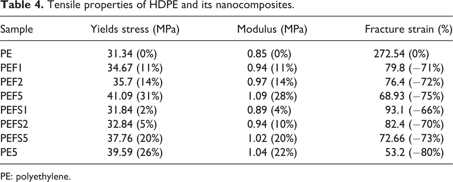
Figure 5 shows the stress–strain curve of HDPE and its nanocomposites, also tensile properties of HDPE and its nanocomposites are listed in Table 4. As it can be seen, the addition of 5 wt% of pristine CNT to polymer increased the yield strength and Young’s modulus by 26% and 22%, respectively (compared to HDPE). A sharp drop in flexibility and strength enhancement depend on different parameters such as high aspect ratio of CNTs, strong van der Waals forces, and π–π interaction between CNTs, which leads to the creation of CNT’s bundles in matrix. Relative fragility of CNT’s bundles acts as a stress concentration point and gives rise to embrittlement and reduction of composite flexibility, which is similar to others’ results. 43,44 Furthermore, smooth surface of CNT and its surface energy difference in comparison to HDPE creates a weak interaction between them. This is an obvious reason for fabrication of weak interface and lack of good load transfer between matrix and CNT in PE5 composite compared to PEF5 and PEFS5 samples. It is similar to the results of Jin et al., 29 they attributed the drop in ductility to entanglement between CNTs and polymer chains. 29
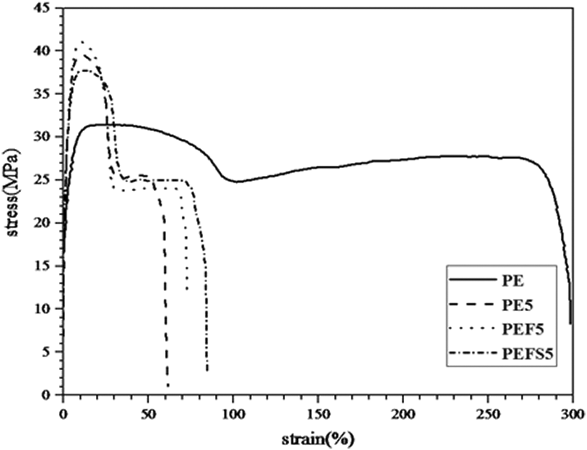
Stress–strain curve of HDPE and its nanocomposites.
Tensile properties of HDPE and its nanocomposites.
PE: polyethylene.
As seen in Figure 5, not only strength properties but also flexibility of PEF5 improved compared to PE5. Functional groups on the surface of CNTs (as the result of acid treatment) lead to improvement of CNTs’ reactivity and decrease their agglomeration in matrix. This will result in enhancement of interface, entanglement, and interlocking between CNTs and polymer. Therefore, an improvement can be seen in interface strength between secondary phase and matrix.
The enhancement of flexibility and reduction of yield strength and Young’s modulus of PEFS5 compared to other nanocomposites are shown in Figure 5 and Table 4. It can be attributed to the softening nature of stearate groups on the surface of CNTs, which decreased the polarity difference between CNTs and HDPE. Therefore, it increased the surface roughness of CNTs and interaction between CNTs and PE. As Figure 2 suggests, the number and size of CNT’s bundles in PEFS5 decreased which led to decrease of stress concentration zone and homogenous distribution of CNTs in matrix. The mobility of polymer chain increased the presence of SA on the surface of CNTs, which resulted in reduction of energy required for rotation of polymer chains to the load direction. However, according to Table 4, increasing the crystallinity of PE in PEFS5 sample prevented the dramatic drop of composite strength.
For more precise examination, the mechanical properties of all samples are calculated and presented in Table 4. For all samples, the increment trends in the yield stress and Young’s modulus were observed by increase of functionalized CNTs weight percentage; however, fracture strain showed a descending trend. Analogous results indicate the enhancement in strength properties and drop in flexibility with the addition of CNTs in polymer matrix by other researchers. 45,46
Evaluation of fracture toughness
In order to find out HDPE and its nanocomposites resistance to fracture, K Q was calculated by D5045 standard. 38 This is similar to the reports of Sahebian et al., 47 the thickness for the determination of PE plane fracture toughness is more than 255 mm at room temperature. The thickness of the project’s samples was too low to comply with the plane fracture toughness condition. Therefore, it couldn’t satisfy the requirement of LEFM as similar results were determined by others. 47,48
Figure 6 presents the force–displacement of PEF1 nanocomposite. The P Q value was obtained by graphical drawing of force–displacement curve. For this purpose, a line was drawn with 5% smaller slope than that of OA line in the first part of the curve. As Figure 6 shows, P Q point could be determined as a force in intersection of OP5 line and the load curve. Thus, the force value at lower strain is lower than that of point P 5. Fracture toughness (K Q) of composite can be obtained by following equations. For all samples, K Q has been calculated and represented in Figure 7
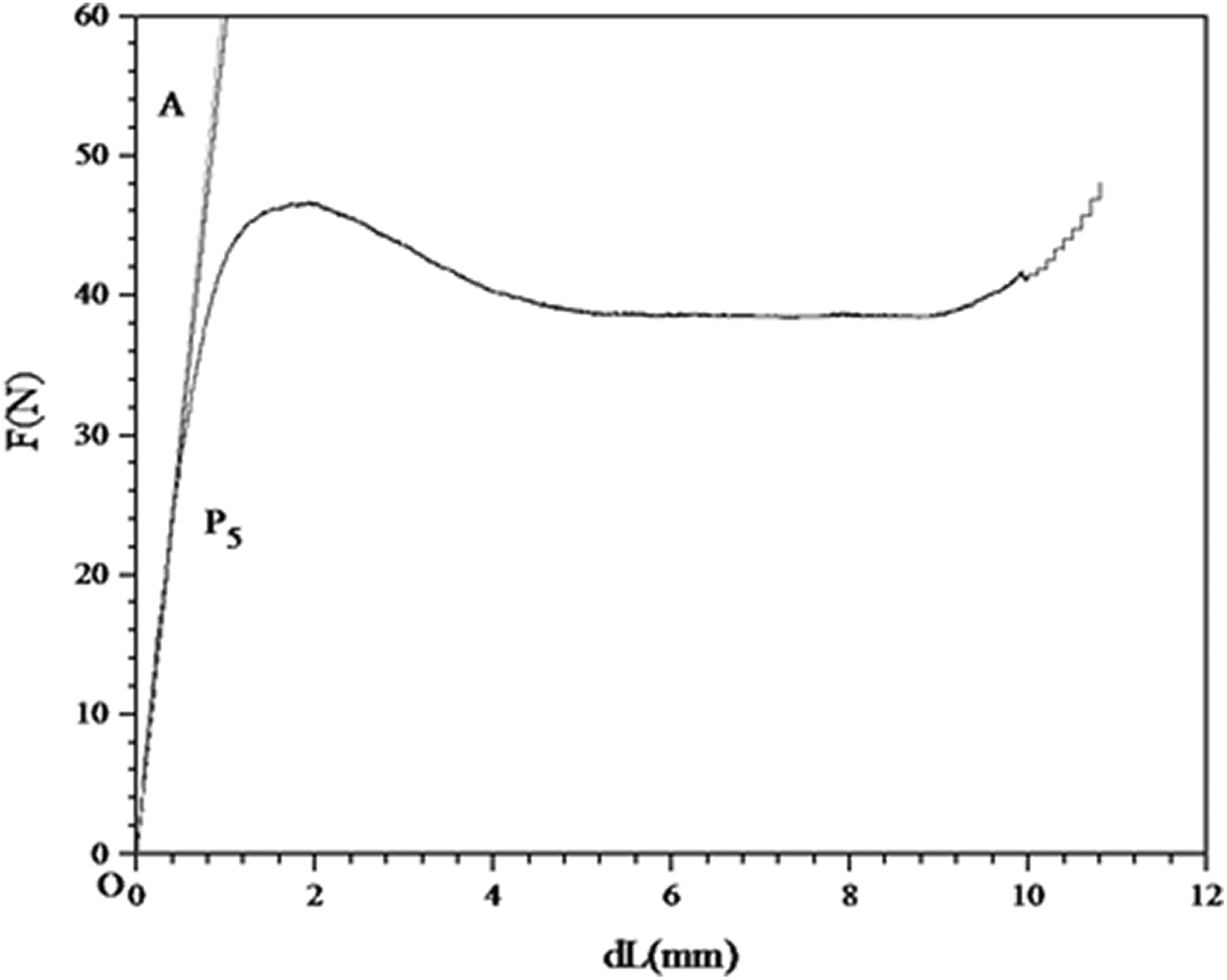
Force–displacement curve of PEF1 nanocomposite.
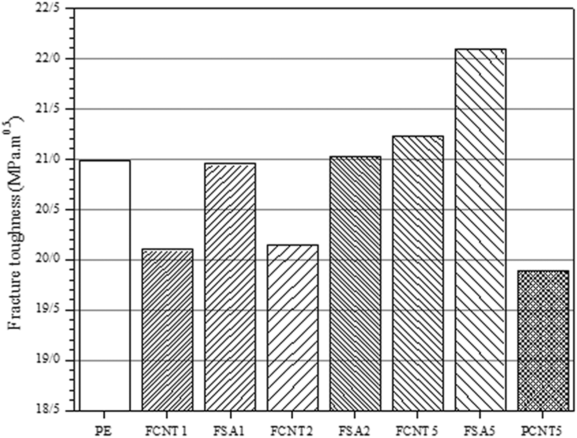
Dependency of fracture toughness on the weight percentage and surface modification of CNTs in HDPE matrix.


where P Q is calculated load; B, W, and a are the specimen thickness, depth (width), and crack length of standard sample for three-point bending test, respectively.
Figure 7 points out the resistance to fracture for pure HDPE and its nanocomposites. As it can be seen, the incremental trend of fracture toughness by increase of the CNTs content is clear. This is opposite to what was reported by Yang et al. The key point in sample preparation is proper distribution of CNTs in matrix. The lack of uniform distribution in matrix by increase of CNTs content resulted in the reduction of fracture toughness. 31 Besides, in comparison with PE5, the fracture toughness of PEFS5 and PEF5 improved 10% and 6%, respectively. It can be said that the surface modification of pristine CNT leads to fracture toughness enhancement of nanocomposite as the result of improvement in CNT dispersion, decrease in stress concentration zone, increase in interface between CNT and polymer, and finally increment of PE crystallinity at the presence of CNTs.
The main contribution of fracture energy is related to the plastic deformation or SWZ in front of pre-crack. 47,48 The effect of both surface modification and CNT content on SWZ is presented in Figure 8 and calculated in Figure 9. As it can be seen, in agreement with Figure 7, it sounds that the surface modification and increment of weight percentage of CNTs will lead to increase of SWZ or enhancement of the materials’ resistance to fracture. In comparison to PE5, the SWZ of PEF5 and PEFS5 nanocomposites increased about 16% and 7%, respectively.
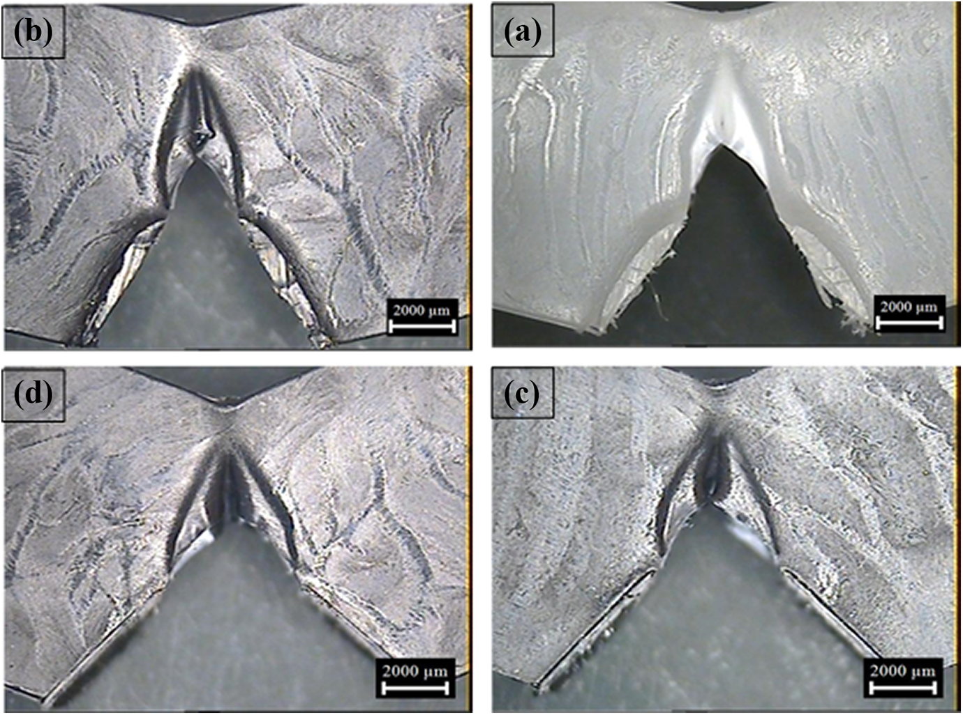
Optical micrograph under cross-polarized light of polished surface of (a) PE, (b) PE5, (c) PEF5, and (d) PEFS5.
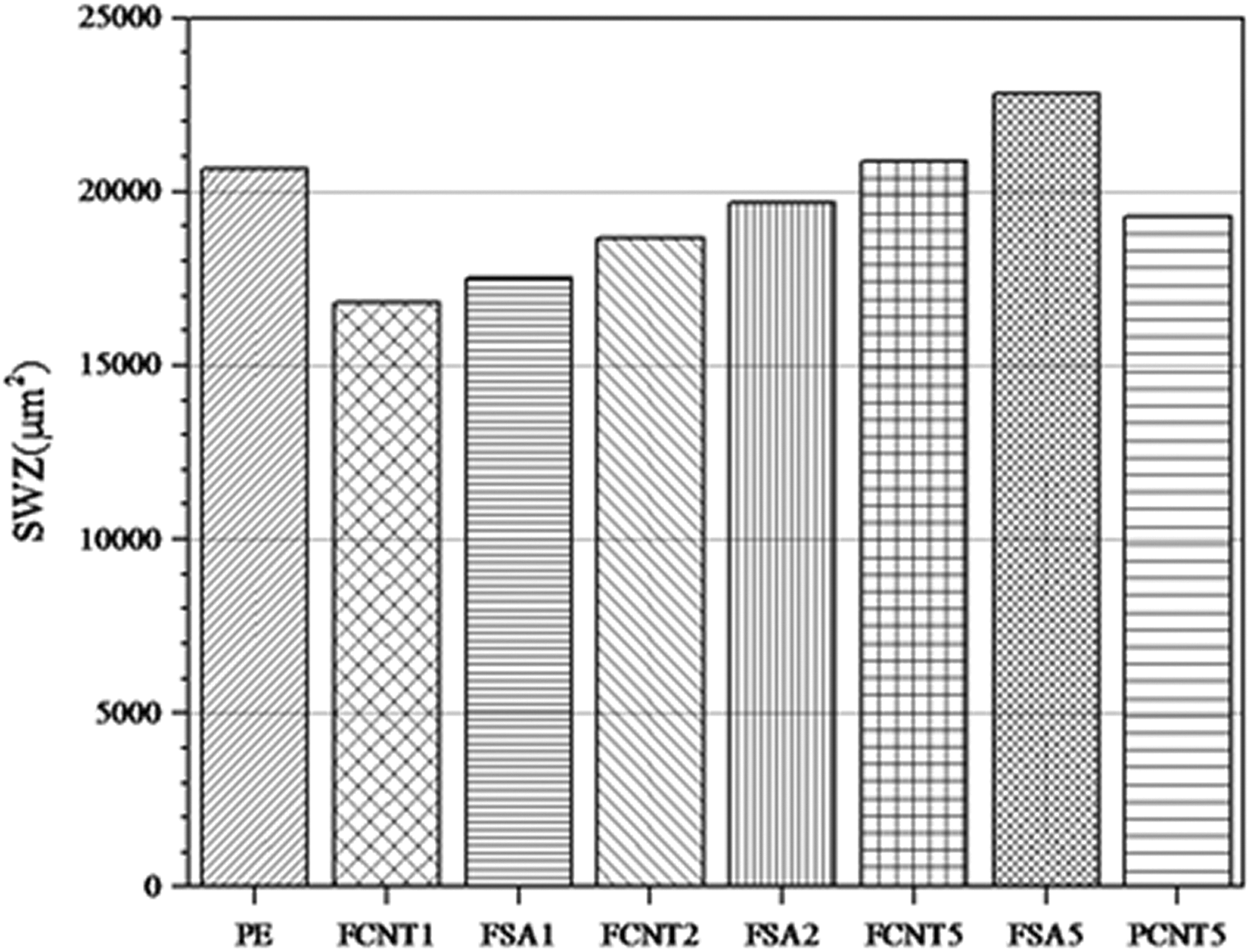
SWZ calculated for PE and its nanocomposites.
Conclusion
The main goal of this research was to evaluate the thermal and mechanical properties of modified HDPE/CNT nanocomposite through differential scanning calorimetry (DSC), tensile and three-point bending tests. Results are summarized as follows: Surface modification of CNT by SA leads to the most significant effect on dispersion of CNTs, and the maximum of crystallinity in HDPE was achieved as compared to the other nanocomposites. Yield stress and fracture toughness have incremental trend by increase of the weight percentage of CNTs in HDPE matrix. Thermal analysis showed that the surface modification of CNTs changes the crystallinity of HDPE as nucleation site and reduction in mobility of polymer neighbors with CNTs. Calculated SWZ and fracture toughness in PEFS5 increased significantly in comparison with other nanocomposites.