
Abstract
Fully impregnated fiber-reinforced thermoplastic sheets, or the so-called organic sheets, allow the thermoforming of parts within very short cycle times. This article describes the development of the next generation of organic sheet materials based on recycled carbon fibers and polyamide 6 staple fiber yarns. Regardless of the recycled nature of the fibers and an average fiber length of 25 mm, the organic sheets still reach a comparable level of the tensile strength and modulus of continuous fiber-reinforced organic sheets made of virgin CF with the same reinforcement structure. Due to the staple fiber yarn architecture, the organic sheets feature a deep-drawing ability of a total plastic deformation up to 50% in the fiber direction. The effect is enabled via an interfiber sliding when the organic sheet is processed in the molten condition. The creation of a finite element model for the thermoforming process simulation of the material is also presented. Predictions of the plastic strain distribution and its magnitude are shown to agree well with forming experiments where a curved geometry is formed to different depths.
Introduction
The continuing increase in demand for fiber-reinforced polymer composites (FRPCs) 1 leads to a correlating rise in carbon fiber waste. This valuable waste occurs in the form of in-house production waste (post-industry) and end-of-life wastes (post-consumer). On a macroscale, the reestablishing of carbon fiber waste into recycled carbon fiber (rCF) FRPC components can be split in two steps: the recycling of the carbon fibers (CFs) and the processing of rCF to manufacture new components. The recycling of CF can be realized by the employment of different techniques as, for example, mechanical recycling (milling and hammering), solvolysis, or pyrolysis. The latter has been established on an industrial scale. 2 Oliveux et al. listed commercial companies and pilot plants for FRPC pyrolysis in her renowned review of FRPC recycling in 2015. 3 Thus, commercially recovered CFs and in-house fiber wastes (cutoffs, prepreg waste, and rejected parts) are available.
In this article, the so-called staple fiber organic sheets—an rCF semifinished product—are introduced. A short overview of the processing route is given and the mechanical properties (tensile, bending, and impact) are presented. The main subject of this article is the investigation of a deep-drawing ability during the thermoforming process, which exceeds the state-of-the-art thermoforming by featuring the plastic deformability of staple fiber organic sheets in the molten state. The results of deep-drawing experiments will be compared to a newly developed material model to simulate such part manufacturing processes. The presented results show that this processing route for rCF is a promising approach to reach the goal of a true recycling, where the properties of material are maintained at the best level possible.
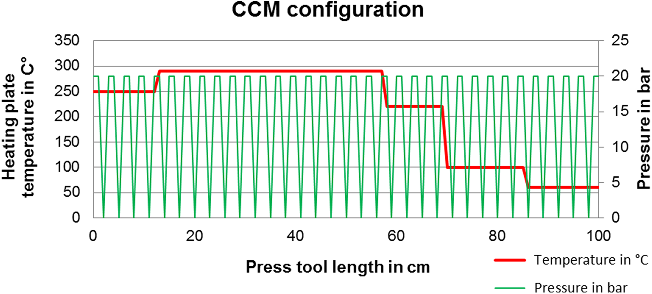
Research has undertaken significant effort to develop processes for the manufacturing of rCF-components and the referring semifinished products. To provide an overview on the state-of-the art in rCF processing, a summary from Pimenta and Pinho 4 is adapted and extended with latest rCF developments as shown in Table 1. The classification of tensile modulus and strength as low, medium, and high is a qualitative indication of achievable performance levels and will only be used as a rough orientation as they depend on the degree of alignment, reinforcement directions, and fiber volume contents.
Overview of state-of-the art rCF processing.
NCF: non-crimp fabrics; rCF: recycled carbon fiber.
In general, it can be stated that research in the field of CF recycling and the manufacturing of recycled carbon fiber reinforced polymer composites (rCFRPC) have made significant progress over the past decade. Thermoplastic rCF compounds for injection molding (Connor 6 and Kreibe 22 ) and compression molding of semifinished products, such as rCF BMC and sheet molding compound (SMC) (e.g. Allen, 8 Turner et al., 9,14 Pickering et al., 12 Szpieg et al. 23 ), were thoroughly researched. The first SMC parts made of rCF are already in application, for example, in the BMW 7 series. 24
A mechanically superior processing route was followed by various authors (Schlichter, 25 Wong et al., 26 Geiger, 13 Hofmann et al., 27 Wolf 28 ) by developing nonwoven products such as veils and mats. First industrial processed products in the area of nonwovens are already available. 29 –31
Meredith et al. 32 investigated the recyclability of used prepregs with a 2 × 2 twill fabric carbon fiber reinforcement. The intention was to pyrolyze the prepreg in its proprietary structure to preserve the twill fabric and facilitate further progressing into second life components. Even if this is a very special case, it shows the high motivation in research to provide new rCFRPC manufacturing processes. Current research is concentrating on recycling routes with aligned rCF, such as manufacturing of aligned mats, wovens, and noncrimp fabrics (NCF) for organic sheets. 12,21,32 –38 Recycling of CFs for high-performance materials is strongly in focus. The aim of this article is to introduce CFs as long and as aligned as possible into new structures.
Textile production processes allow the processing of rCF in the fiber length range of more than 20 mm. The process chain for rCF staple fiber yarns is a current topic in the field of research and development. Known carbon staple fiber yarns as, for example, produced by Schappe 39 are manufactured in a stretch breaking process. Therefore, new carbon fiber rovings are processed into staple fiber yarns. Because of the particular challenges involved in the processing of rCF (e.g. inhomogeneous fiber length distribution, differing sizing on the fibers, and foreign fibers), the research results cannot be transferred to the production of rCF yarns or tape structures. This fact is taken into consideration in current research projects. 18,20,21,40 –43 In addition to developments on rCF yarns, efforts are also being made to process the fibers into oriented slivers and tapes. 44 –46
Examined materials and processing
Fiber
Fibers of the type Toray T700GC-24 k were used as input material. 47 These fibers were provided on waste spools and later cut into staple fibers with a defined length of 80 mm as preprocessing step. For the experiments and process development in this article, these fibers were used to assure a stable and reproducible material input. According to Abdkader et al., they can be referred to be rCF type 1, “dry fibers from production leftovers and cut-offs.” 20 Nonetheless, the process developed in this work could also be applied on recycled fibers of other types, for example, pyrolyzed rCF.
Matrix
For the matrix material, polyamide 6 (PA6) fibers in raw white color from EMS, type Grilon P300, were used. 48 They provided a staple fiber with a circular cross section, length of 60 mm, a density of 1.14 g/cm3, and a melting temperature of 222°C. When homogeneously mixed with the rCF staple fibers, the PA6 staple fibers then support the carding process during yarn production due to its crimp of 6.5 B/cm. RCF and PA6 fibers in combination are the input material for commingled hybrid yarn manufacturing.
Yarn manufacturing
The yarns were manufactured in a multiple step process. The cut rCF staple fibers and PA6 fibers were mixed and opened by a pin roll. The fiber blend was then aligned in a carding process and converted into a sliver. Due to a lack of compaction and solely maintaining their shape because of fiber friction forces, the slivers must be converted into more processable yarns to be suitable for textile fabric production. 49 Spiral covering yarn spinning was chosen as the suitable manufacturing technique using a PA6 multifilament with 156 dtex count and 36 filaments in cross section as covering yarn. 50 Abdkader et al. investigated different yarn spinning techniques and support this decision. 51 Different yarn structures can be adjusted by varying a set of parameters, for example, modifying the winding frequency and winding force of the PA6 multifilament. In the present case, the yarns were structurally optimized for use in NCF production. In total, 800 tex and 400 tex yarn counts were produced to serve as warp and weft. The yarn manufacturing was done by the German Institutes of Textile and Fiber Research Denkendorf (DITF). 40,52
NCF manufacturing
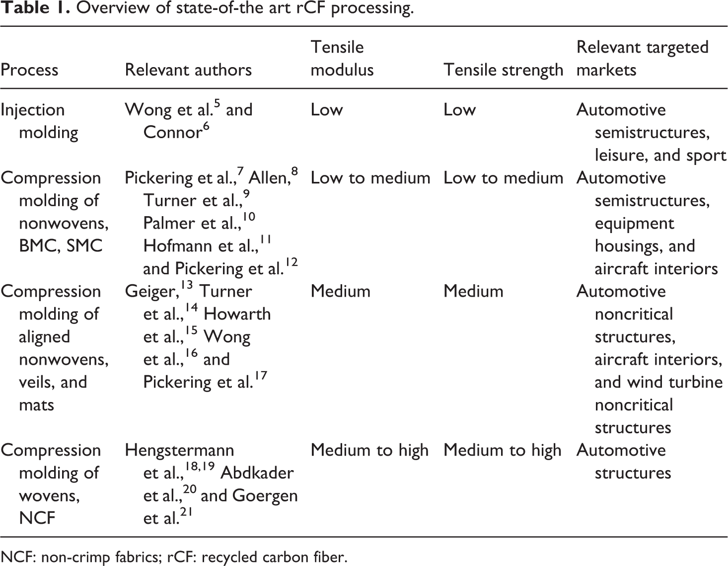
The staple fiber yarns were processed in NCF using a crochet machine. Crocheting the yarns provides better overall drapeability of the NCF, since warp and weft are able to slide within the crocheted tunnels. Figure 1 shows the NCF structure used in this work in detail. Two 800 tex warp and four 400 tex weft yarns per centimeter NCF were used, hence the fabric is balanced in both axes. A PA66 monofilament was used as the crochet yarn. Due to the fact that the NCF already contains 55 vol% PA6 matrix, it can be directly used as a hybrid input material for organic sheet production. Therefore, additional matrix is not necessary for organic sheet manufacturing and the hybrid NCF preform is an alternative to film stacks, powder prepregs, and so on. The manufacturing of the NCF material was done by Gustav Gerster GmbH & Co. KG, Biberach, Baden-Württemberg, Germany. 53
Detailed plan view of rCF/PA6 non-crimp fabric. From top to bottom in the background: 800 tex warp yarns (1). From left to right in the front: 400 tex weft yarns (2). White spiral covering yarns: PA6 multifilament yarn (3). Transparent filaments: crocheted mesh made with polyamide 66 monofilaments (4).
Manufacturing of staple fiber organic sheets
Organic sheets provide various advantages such as fast cycle times by thermoforming, good storability, and easy handling. 54 –56 However, in contrast to these benefits, there are also significant disadvantages. A restricted part complexity and in case of CFs the high price are the most important ones. The development of staple fiber organic sheets made of rCF and PA6 aims to eliminate these drawbacks by providing the use of economically competitive rCF and enabling a deep-drawing ability because of the staple fiber architecture.
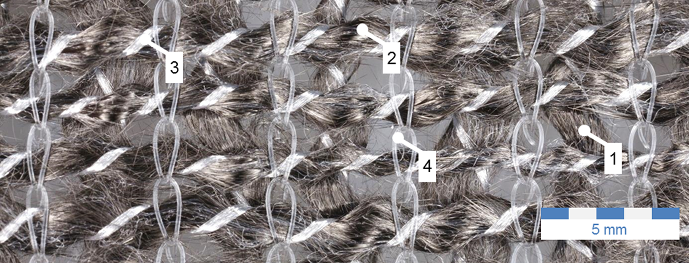
To manufacture the organic sheets in this work, four staple fiber NCF layers were stacked into a 280 mm wide laminate with a consolidated thickness of 0.90 ± 0.05 mm. In each case, the warp yarn sides of the layers were placed facing one another to foster nesting effects and reduce the pore volume to be filled with matrix (cf. Figure 2).
Lay-up structure of NCF for manufacturing of organic sheets.
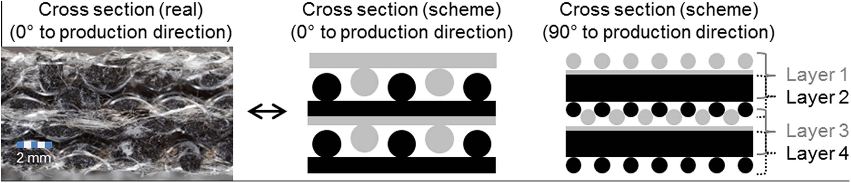
Organic sheets were produced in the warp direction using a continuous compression molding machine (CCM). A temperature profile with 290°C peak temperature in combination with 20 bar pressure on the laminate for an exposure time of 233 s was chosen (cf. Figure 3). The laminate was manufactured at a production rate of 10.8 m per hour.
CCM configuration for the production of rCF/PA6 staple fiber organic sheets. The diagram data show only the machine configuration, the real temperature profile was not measured, but it is expected to smoothly follow the assigned platen temperatures.
Characterization of staple fiber organic sheets
The produced staple fiber organic sheet was tested with regards to fiber volume content, impregnation quality, tensile strength and modulus, bending strength and modulus, and Charpy impact strength. The impregnation quality was investigated by looking at cross sections of the material in the production direction (0°) and perpendicular to it (90°) using scanning electron microscopy (SEM). Figure 4 shows the related photomicrographs.
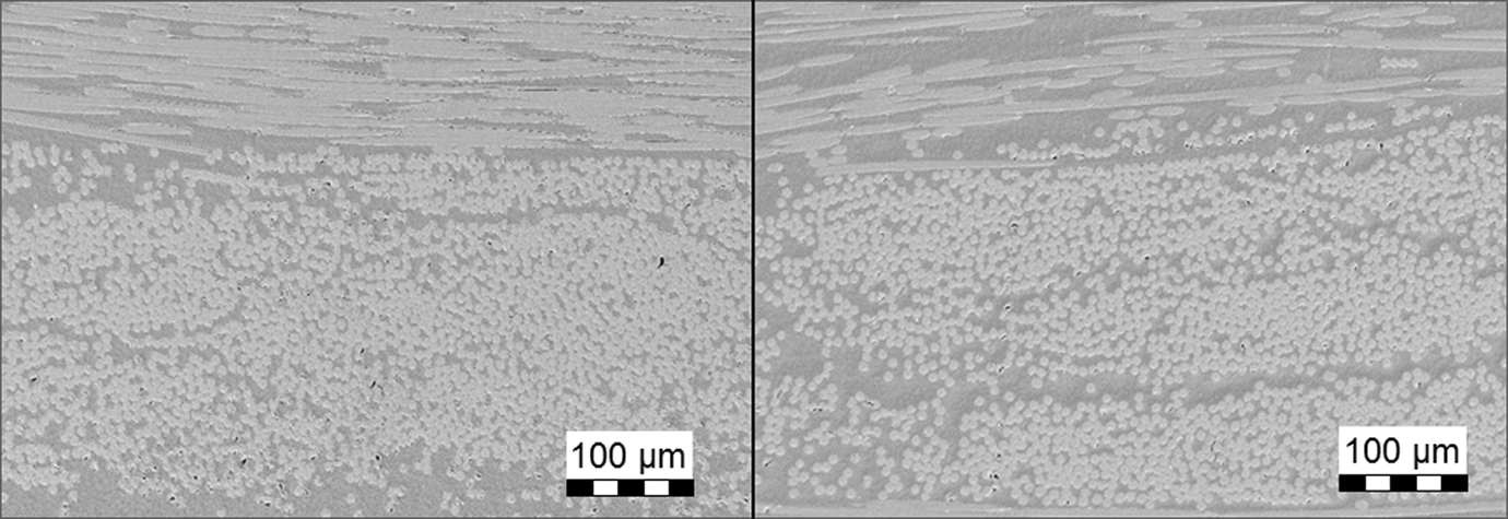
Micrographs. Left: 90° to production direction. Right: 0° (production direction).
It can be stated that the impregnation quality is satisfied and almost no pores could be detected. The small sized black areas mainly represent preparation defects. Also, both in production direction and perpendicular to it, the impregnation quality is equal. Especially in the CCM process, the impregnation perpendicular to the production direction is challenging as the air needs to be displaced at right angle to the impregnation front and can be easily trapped within the laminate. The fiber volume content was determined to be 45%. The tensile modulus and strength were investigated in warp as well as weft direction. Ten specimens per direction were prepared and conditioned in a convection oven for 7 days at 80°C. End tabs were applied on specimens with Loctite “UHU PLUS Endfest 300” glue to avoid failure at the restraint due to tension peaks. Weft specimens were cut into specimens 250 mm in length and 15 mm in width, whereas in the warp direction, the specimens were cut 250 mm long and 25 mm wide to reduce the risk of variations in experiments due to incomplete cross sections of 800 tex yarns. Warp and weft specimens were tested on an universal testing machine from manufacturer ZwickRoell, type 1485, based on the specification of the DIN EN ISO 527-4 standard with the above mentioned modification in width. The results are presented in Figure 5.
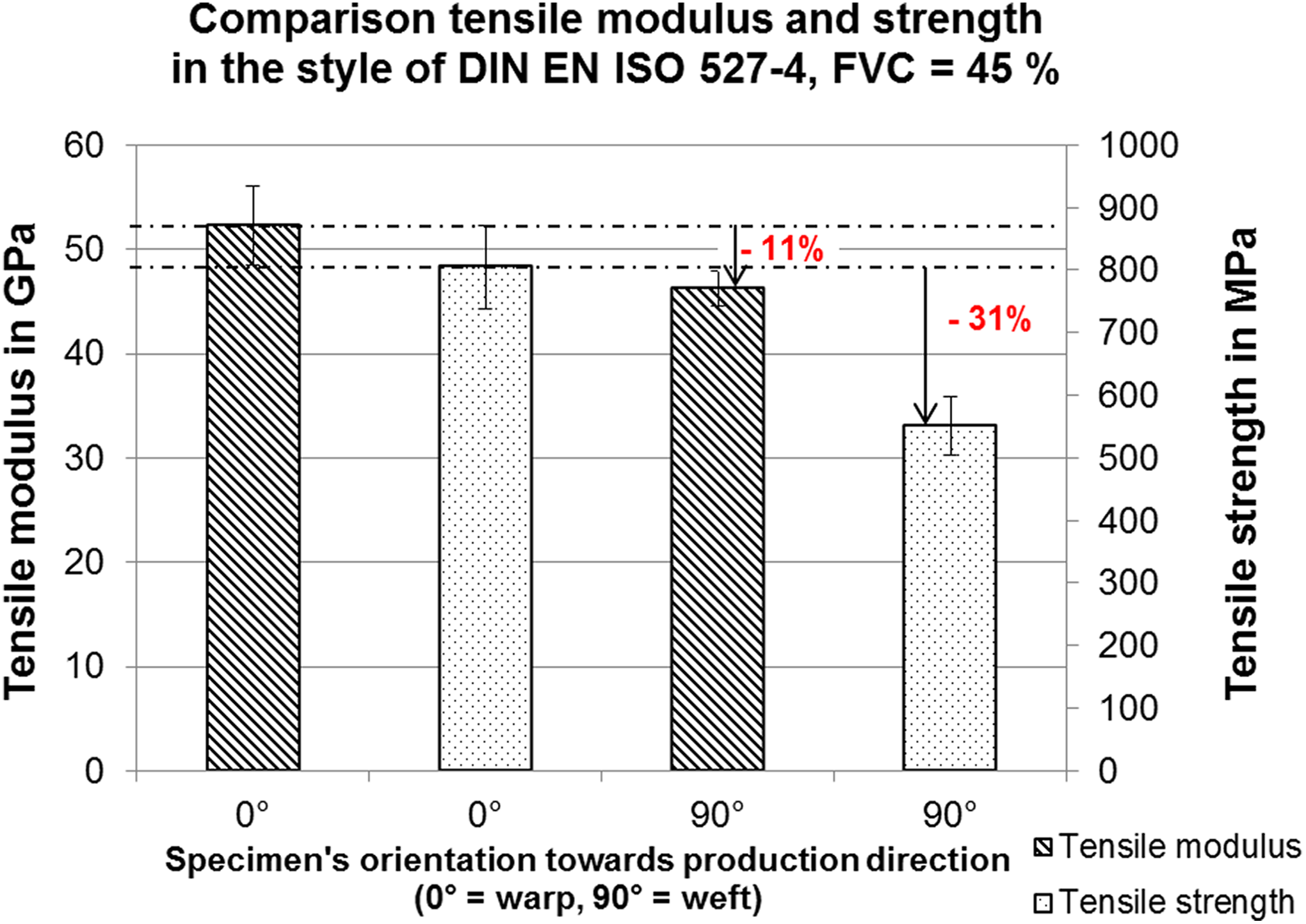
Comparison of tensile modulus and strength between tensile tests stressing warp and weft yarns.
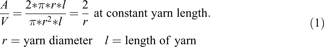
It is notable that the weft specimens showed significantly lower results for tensile strength (−31%) and modulus (−11%). Apart from specimens’ dimensions in width, there were no differences in test set-up. Thus, it is probable that the difference in performance is material related. One explanation could be found in the yarns. Due to the lower titer of weft yarns, the relation (surface area)/(volume) (A/V) of the yarn is higher compared to warp yarns.
During yarn production, very short CFs and carbon fiber dust are removed from the yarn due to mechanical stress and lack of friction between fibers in the yarn. Conversely, the PA6 fibers are not affected by this effect due to their crimp. A higher A/V-ratio favors this effect. In consequence, warp yarns provide a higher fiber volume content (FVC) compared to weft yarns, even if the initial FVC in the slivers are equal. Studies conducted by the German Institutes of Textile and Fiber Research Denkendorf (DITF) with rCF/PA6 staple fiber yarns showed that this difference in FVC can reach 10%. But, it cannot be ruled out that there are additional factors responsible for the poor tensile values in weft direction and further detailed investigations are necessary. One approach could be the analysis of fiber lengths in the warp and weft yarns. Possible reasons of fiber length shortening in the case of weft yarns are yarn structure (higher winding frequency fostering breakage) and mechanical stress in NCF production. According to Thomason et al., 57 fiber stiffness is less sensitive to shorter fiber length than strength, but this does not fit the tendency of the mechanical values for the weft yarns presented in Figure 5. Another hypothesis is that the off-axis angles in the warp yarns are lower than in the weft yarns. More precisely, the warp yarns contain a core area where fibers are highly oriented within the yarn and where the weft yarns miss this fiber core due to their smaller diameter. Tensile strength is more affected by off-axis angles than tensile modulus, which would explain the given results. 58
Standard deviations of tensile tests were showing values of <10%, which is considered to be acceptable, facing the fact that staple fiber organic sheets provide no continuous reinforcement by rovings.
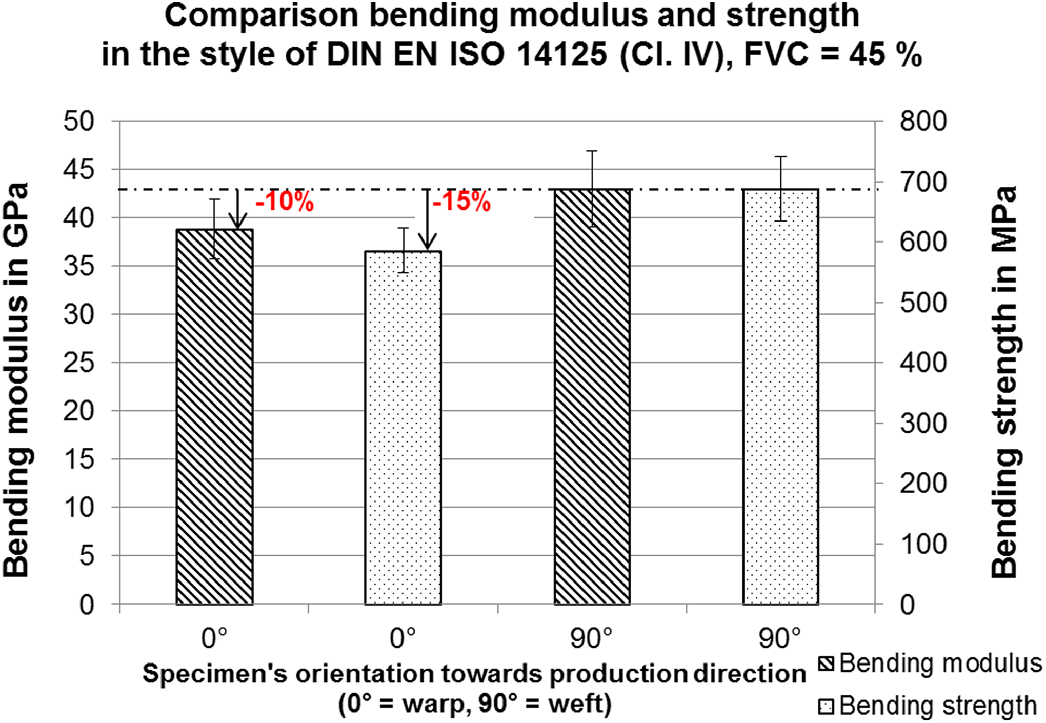
Bending properties were tested in the style of DIN EN ISO 14125 (class IV). The results are shown in Figure 6. For the warp and weft direction, nine specimens for each were tested. Specimens tested in the warp yarn direction (long side of the specimen in warp direction) showed a lower overall performance in modulus (−10%) and strength (−15%). This can be explained by the laminate structure as shown in Figure 1. Weft yarns are located at the outer and inner layers, whereas warp yarns are only located inside the single layers. This leads to a higher distance of weft yarns to the laminate axis compared with warp yarns. Because the distance has a quadratic impact on the bending properties according to Steiner’s theorem, higher values can be explained even if not all weft yarn layers are located at the outer layers of the laminate but also in the middle of the laminate.
Comparison of bending modulus and strength between tensile tests stressing warp and weft yarns.
Charpy impact resistance was again tested by stressing the specimens in warp and weft direction in the style of DIN EN ISO 179-1. Figure 7 shows the related results. Again, nine specimens per direction were tested. The tests were conducted with a CEAST impact tester type 6545 using a free-swinging hammer without loss of energy. Both test series showed comparable results. Specimens in the warp direction showed an average impact resistance of 66 kJ/m2, and in the weft direction 60 kJ/m2. Both test series showed relatively high standard deviations of 11 and 13 kJ/m2, respectively.
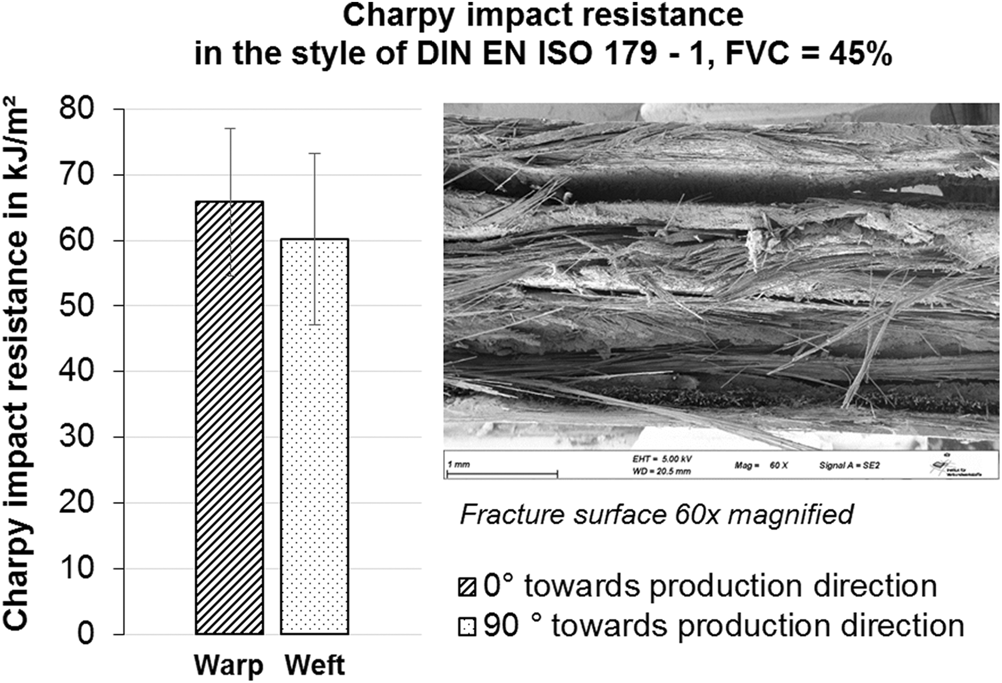
Charpy impact resistance results and micrograph of fracture surface.
The mechanical properties of the staple fiber organic sheets are condensed in Table 2.
Summary of mechanical properties of rCF/PA6 staple fiber organic sheets with average FVC of 45 vol%.
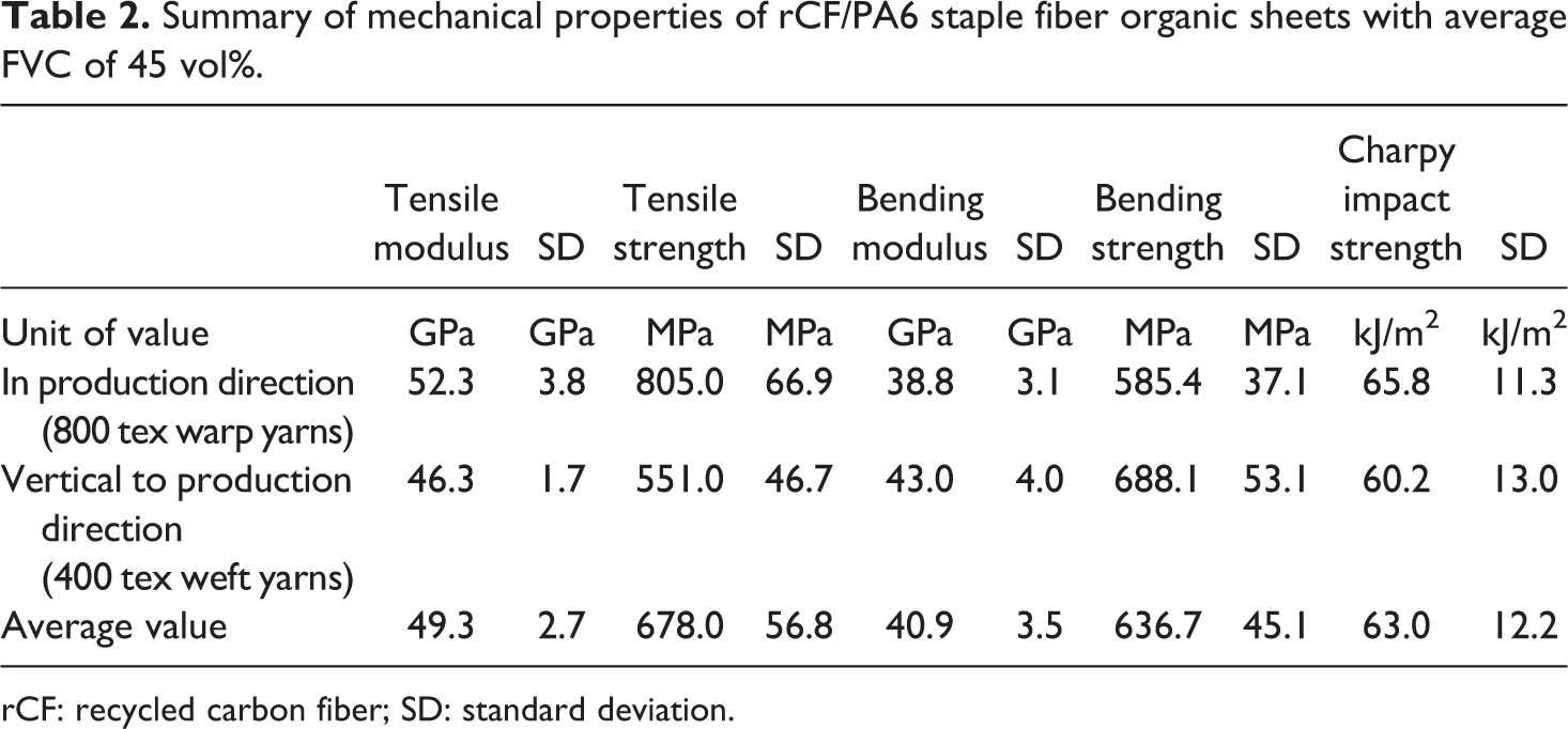
rCF: recycled carbon fiber; SD: standard deviation.
Theory on deep-drawing staple fiber composites
In contrast to continuously fiber reinforced organic sheets, staple fiber organic sheets can be plastically deformed in the fiber direction as long as the thermoplastic matrix is in molten condition.
Theoretically, two effects can be observed when deep drawing staple fiber organic sheets. First, due to the spiral covering yarn manufacturing, the winding filament causes a waviness in yarns. The wavy yarns and CFs, respectively, straighten under tension as long as the surrounding matrix is molten during the thermoforming/deep-drawing process. Next, single fibers slide along one another in the molten matrix, causing a material elongation in the fiber direction. As volume constancy applies, the organic sheets thin out in thickness direction. Figure 8 shows the aforementioned hypothetical effects schematically. A major question regarding the staple fiber deformation behavior is the controllability and homogeneity of the resulting organic sheet’s deep-drawing behavior. Therefore, in this research work, organic sheets were deep drawn to different degrees of plastic deformation to investigate the reproducibility of deforming such organic sheets. The intention of this article is to prove the concept of deep-drawing staple fiber organic sheets. A detailed evaluation of the mechanisms leading to a deep-drawing ability will be pursued in future research and based on the findings of this research work.
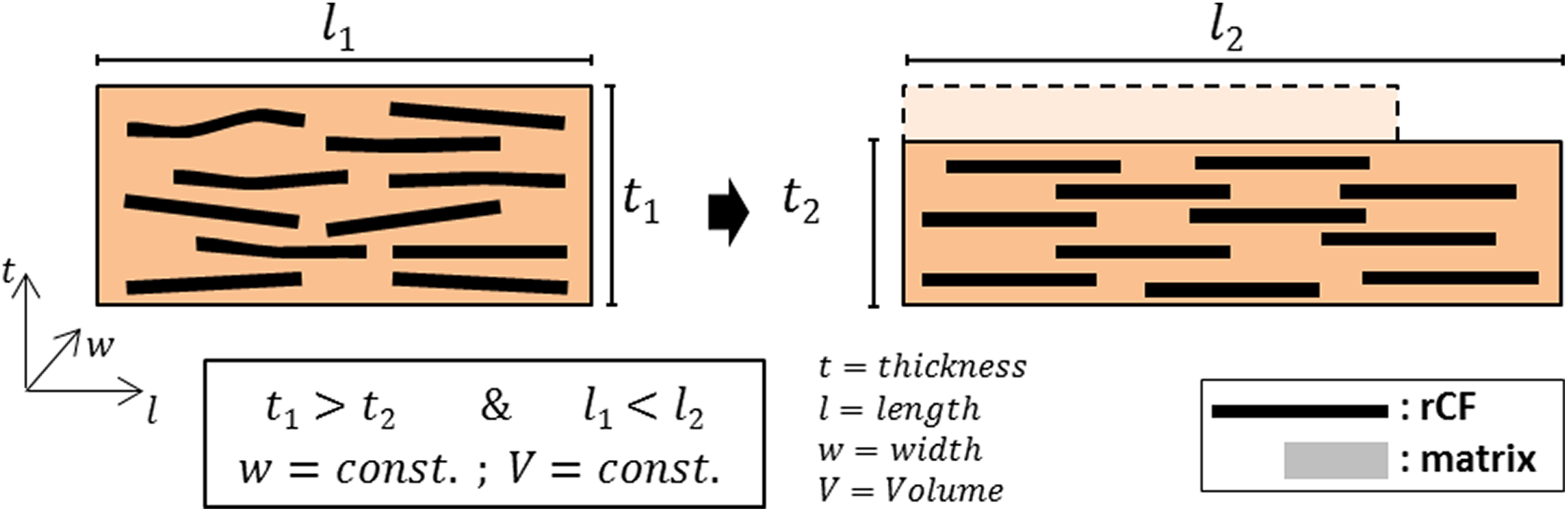
Schematic of plastic deformation mechanism in staple fiber organic sheets.
Design of experiments—Deep drawing of staple fiber organic sheets
To investigate the deep-drawing ability of staple fiber organic sheets at an industrial scale, a specific deep-drawing mold was designed (cf. Figures 10 and 19). Organic sheets are completely fixed in a frame by clamping and are additionally screwed together with the frame (cf. Figure 9). The screw ensures an elimination of any material pull-in during thermoforming and serves as a predetermined breaking point in case of a material pull-in. The mounted specimen length (free lengths for thermoforming) is 200 mm. Two different mold modules are used to realize a two-dimensionally deep drawing to resulting lengths of 250 and 300 mm, respectively. Figure 10 shows the mounted mold in an 80 t thermoforming press with the referring infrared (IR) heating panels in the background.
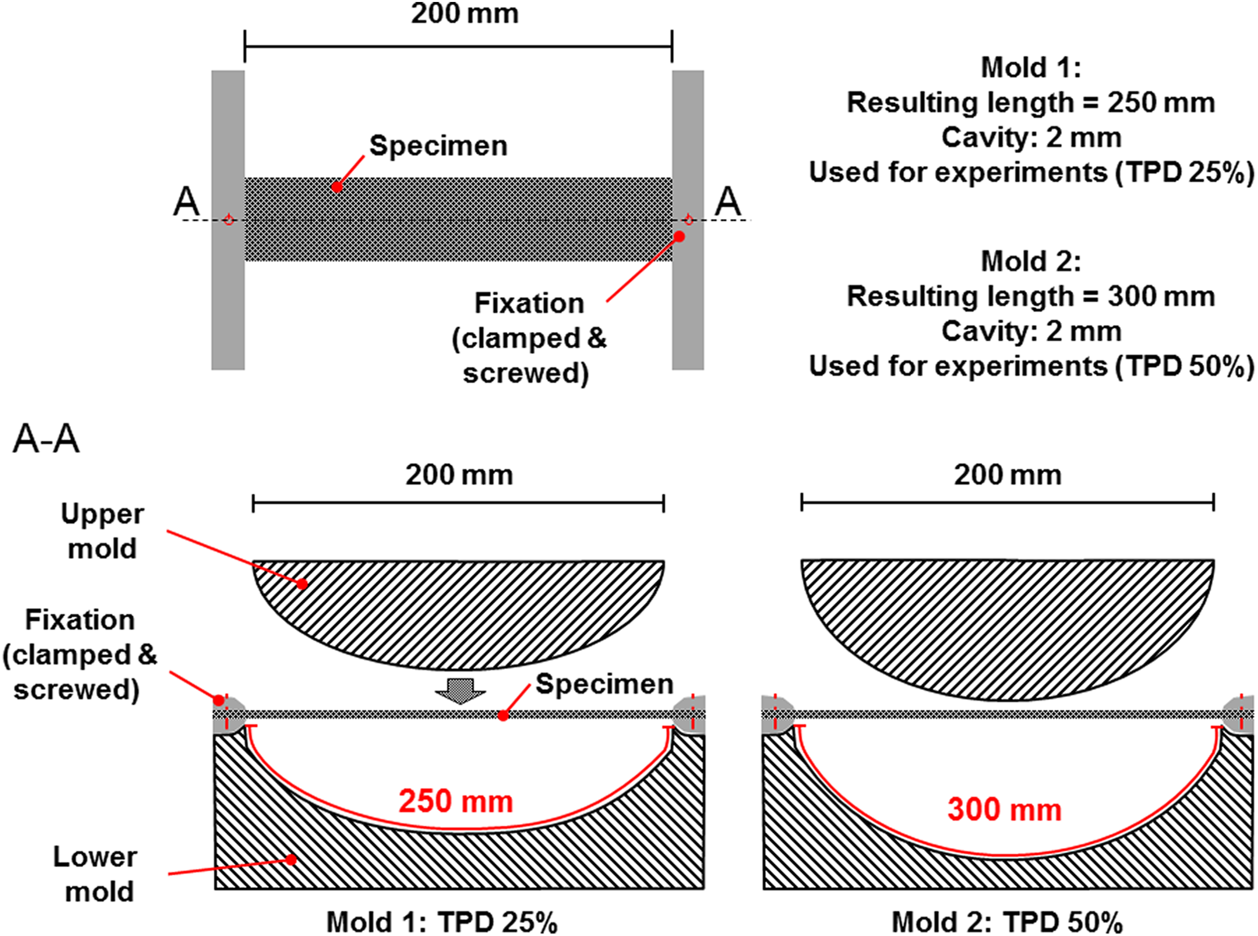
Specimen mounting and tooling set-up.
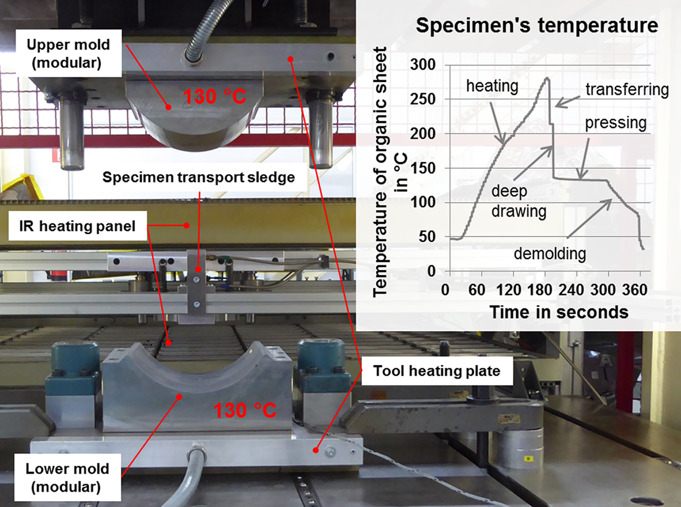
Mounted mold in thermoforming press. At the back: infrared heating panels with transport sledge. Right corner: example temperature profile of a blank specimen during the process.
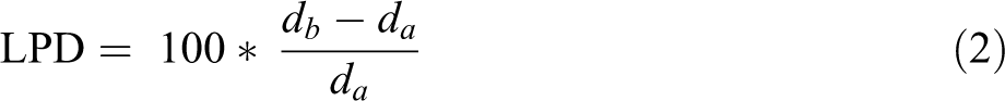
The specimen’s outer dimensions were 300 mm in length and 80 mm in width. One hole on each side was drilled for the screwed fixation in the tool frame (cf. Figure 9). Two different laminate thicknesses were tested, 0.90 ± 0.05 mm (type 1) and 1.80 ± 0.1 mm (type 2). The specimens of type 1 were cut out of laminates manufactured with the CCM process. For specimens of type 2, two of these CCM laminates were joined by autoclave consolidation. As the CCM laminates already provided a good quality and very low void content, further consolidation due to the autoclave process was not expected. Twenty-two segments of da = 10 mm (mounted length plus 10 mm per frame edge), perpendicular to specimen length, were marked on specimens with alternating silver and gold paint sticks (cf. Figure 11). After deep drawing the specimens, a transparent foil was clipped on the curved specimen (step 1, Figure 11). This foil provides five marking lines at 0, 25, 50 75, and 100% of specimen width. Postprocess segment lengths were measured by marking the new pattern with removable paint, five points per segment. The transparent foil was then removed from specimen and placed on a flat surface (step 2, Figure 11). The postprocess segment lengths were documented in MS Excel by recording five points per segment mark. The distances db between the points in length direction, representing the distance between segment marks, were calculated. The five calculated distance values per segment were averaged. The new segment lengths were related to the original 10 mm length. The resulting value in percent represents the local plastic deformation (LPD) of specimens. The total LPDs per specimen represent the total plastic deformation (TPD).
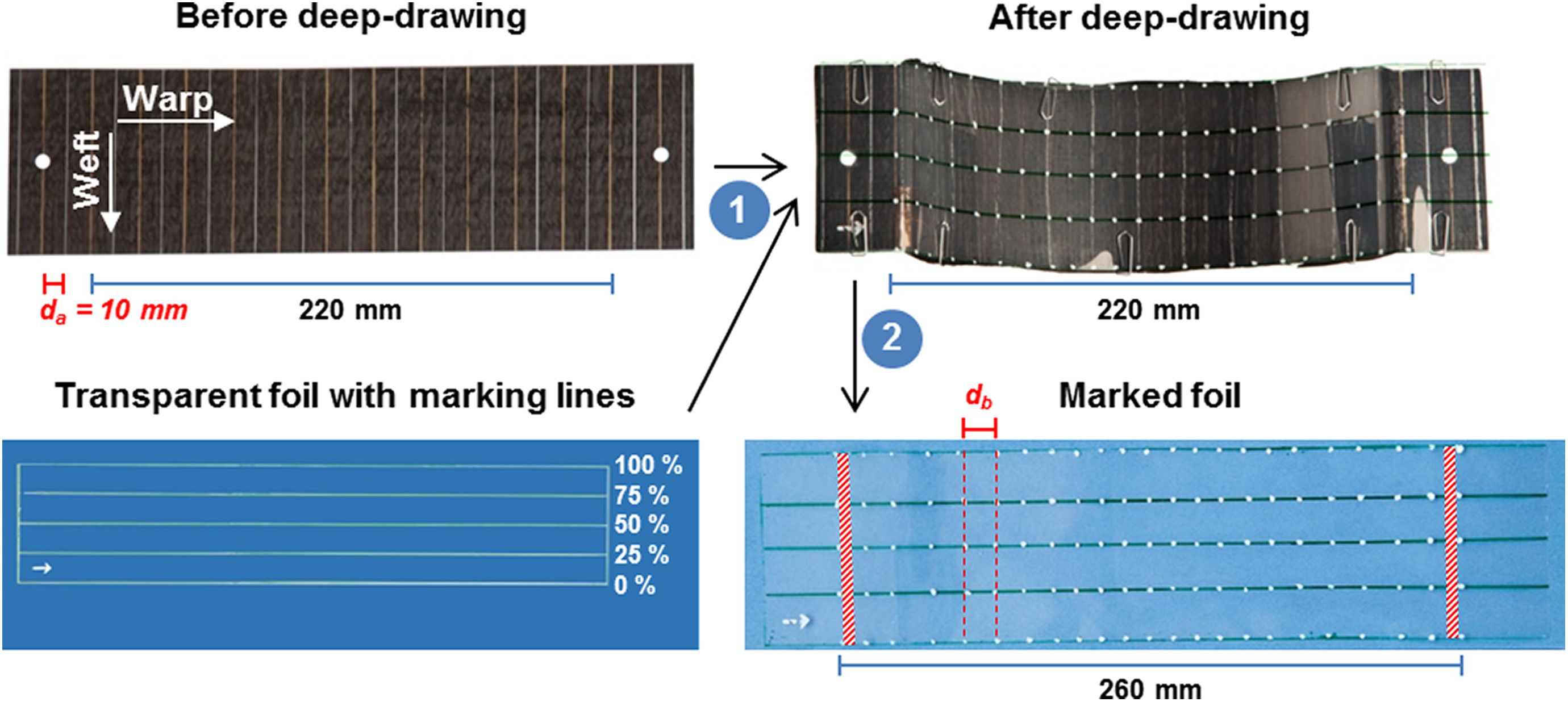
Set-up for evaluation of deep-drawn specimens.
Four test series with five specimens of each series were evaluated. The two parameters “laminate thickness” (LT) and TPD were alternated (cf. Figure 12). For change of LT, specimens of each type 1 and 2 were used for two series. The TPD was 25% and 50%, respectively. The test series were named following a LT-TPD nomenclature (bold names in Figure 12).
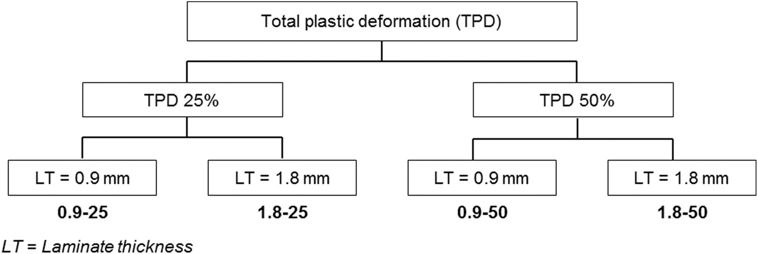
Structure of conducted experiments. Bold: name of test series.
For all experiments, the specimen temperatures were recorded. After mounting the specimen in the frame, it was semi-automatically transferred to the IR heating panels by a transport sledge system. The specimen was heated up to 280°C before it was transferred back into the press area. The mold closed and deep drew the specimen with a pressing force of 80 kN for a pressing time of 120 s. The mold was tempered to 130°C. The temperature diagram in Figure 10 shows the specimens’ temperature development during the process.
Results and discussion
Several findings can be summarized from the experiment results, which are presented in Figure 13.
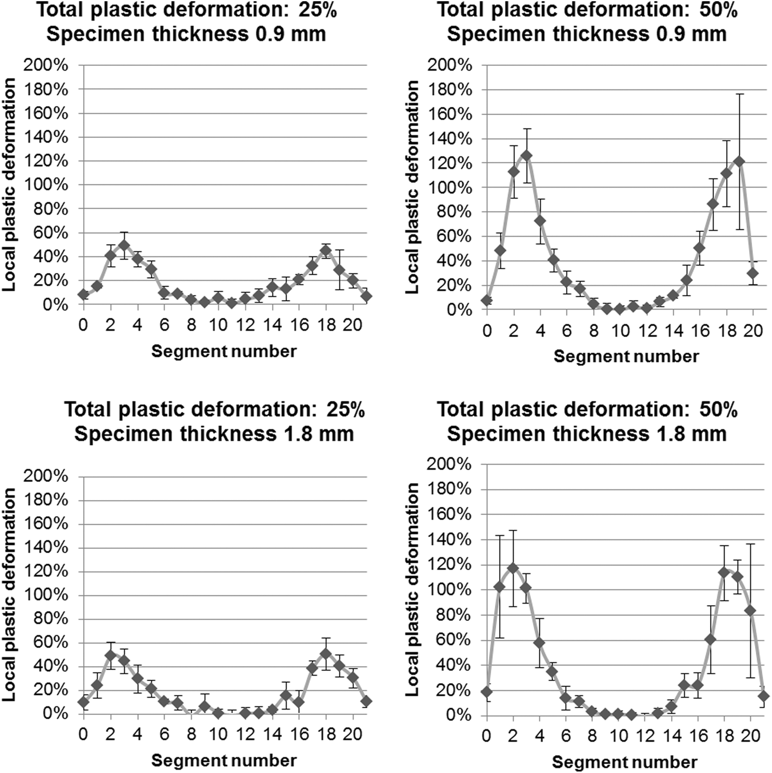
Local plastic deformation per segment.
Firstly, it can be observed that the middle part of the specimens was not plastically deformed in the test series. This is the area of first contact between material and upper mold. As the mold is tempered to 130°C, it can be considered that the matrix immediately cools below melting temperature upon contact and “freezes” the organic sheet. In addition, the temperature of the specimen in the clamping area is also below melting temperature due to the IR shielding of the frame. Due to these two conditions, the plastic deformation takes place symmetrically between the frame edges and the middle of the specimen (cf. Figure 14). While the upper mold closes, the contact between the middle of the specimen and the mold expands toward the sides and the matrix in the contacted areas freezes. The development of the local plastic deformation of the specimens therefore can be considered as visualized in Figure 14 for four qualitative time steps t1–t4.
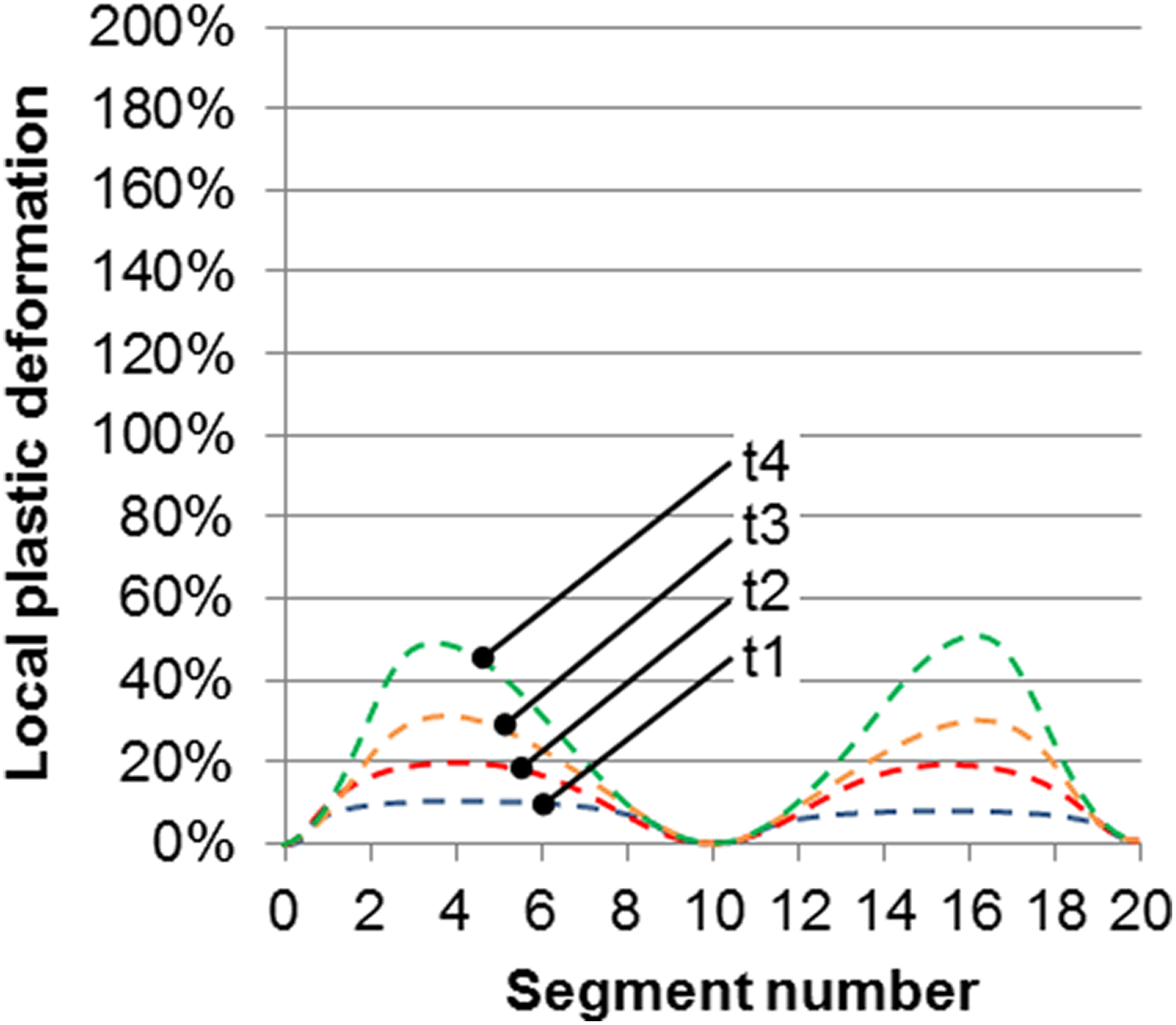
Process of deep drawing and development of plastic deformation in relation of time.
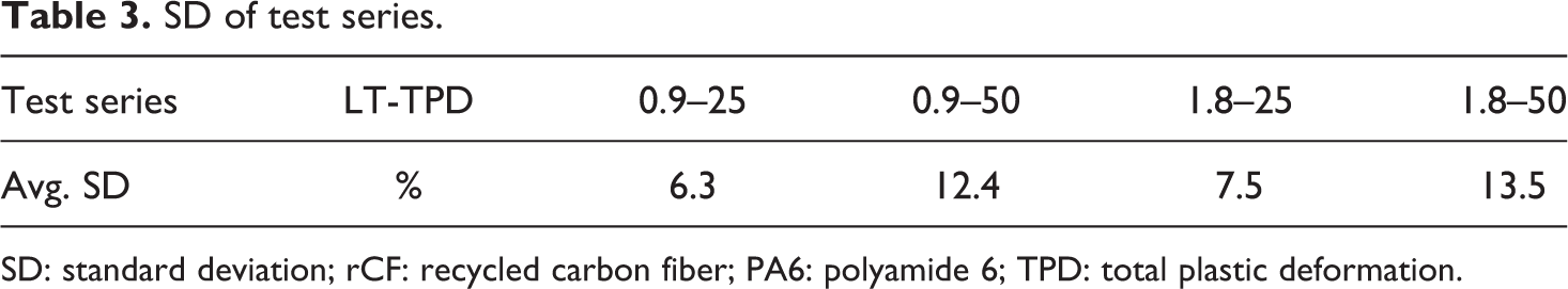
At a TPD of 25%, the standard deviation (SD) for local plastic deformation is equal to an average of 6.3% (type 1) and 7.5% (type 2). At a TPD of 50%, the SD is equal to an average of 12.4% (type 1) and 13.5% (type 2). It can be concluded that the stability of the process is dependent on the TPD (cf. Table 3).
SD of test series.
SD: standard deviation; rCF: recycled carbon fiber; PA6: polyamide 6; TPD: total plastic deformation.
It can be observed that the SD of experiments with specimens of 1.80 mm is higher than for those with 0.9 mm. Due to the higher amount of staple fibers and material in thickness direction, a lower statistical distribution of sliding staple fibers was expected, but could not be proven by experiments as the SD can be considered to be on the same level, independent on specimen thickness (cf. Table 3: SD of test series).
The deep-drawing process of staple fiber organic sheets at a TPD of 25% showed an average SD of 6.9% for both specimen types and can be stated as reproducible. Doubling the TPD to 50% also results in an almost doubling of the SD with an average of 13.0% for both specimen types. However, it can also be observed that areas of LPD <20% show an equal SD in all four test series, and the rise in the total SD for the test series with TPD = 50% is caused by areas with high LPD.
Modeling of staple fiber organic sheet
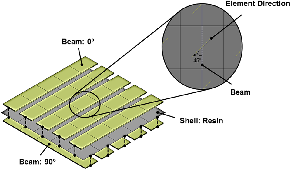
For future prediction of the deep-drawing abilities of the staple fiber organic sheet, a finite element (FEM)-based simulation of the forming process has been performed using LS-DYNA®. Although LS-DYNA® offers the possibility to model the directional and temperature dependency of a woven or non-crimped fabric reinforced organic sheet with its *MAT_249_reinforced_thermoplastic, this material model does not suit the example of a staple fiber organic sheet. The deep-drawing abilities of this material add a plastic range into the tensile behavior of the yarns that is not taken into account by *MAT_249. For this purpose, a hybrid modeling method based on a combination of shell and beam elements has been used as implemented in the works of Duhovic et al. (cf. Figure 15). 59,60
Hybrid modeling approach for modeling organic sheets.
The beam elements are created in the direction of the real yarns inside the organic sheet and define the tensile and bending stiffness. The shell elements represent the in-plane shear stiffness. These two components interact via certain contact definitions, which then define the behavior of the material. This modeling approach allows the flexibility to create even more complex reinforcement structures. In the case of multilayered organic sheets, it is recommended to generate a geometric model of each layer individually and then connect them via contact definitions. This makes it possible to predict delamination and sliding effects between the different layers.
For modeling the correct material behavior, the material models for the shell and beam elements can be chosen individually. In the present case, both element types show a temperature dependent, elastic–plastic behavior. This condition leads to the use of material model *MAT_188_thermo_elasto_viscoplastic_creep for the shell elements and *MAT_004_elastic_plastic_thermal for the beam elements. Thermoforming is a short cycle process, so the creep parameters in the material model used for the shells can be ignored. In the plastic region, the tensile behavior of the shell elements can be defined by a table that shows temperature dependent effective plastic strain versus effective stress curves. As *MAT_188 is not compatible with beam elements *MAT_004 is used to allow the tensile and bending behavior of the composite to be defined via the beam elements. *MAT_004 is a simple linear elastic–plastic model where the mechanical properties can be defined for a maximum of eight different temperature values.
Calibration of the material models
For a first characterization of the tensile behavior of the composite, a tensile test on the staple fiber organic sheet for different elevated temperatures (190°C, 200°C, and 210°C) was also performed. In the test, a UD laminate created by a winding process and consolidation in the autoclave is used. The tested specimen had a dimension of 1.5 mm × 15 mm × 25 mm and an FVC of 50%. The test was performed up to a TPD of 7.5%. LPD on the staple fibers can be much higher but was not recorded.
The difference to a standard organic sheet is the ability of the yarns to stretch before failure. In comparison to the results shown in Figure 5 that were taken at room temperature, a decrease in the tensile strength with increase in temperature can be observed in Figure 16. The decrease in the tensile strength can be explained by the effect of the temperature on the viscosity of the thermoplastic matrix. A higher temperature leads to a decrease in viscosity and to a lubricating effect for the movement of the yarns. After reaching the ultimate tensile strength at 1.0%–1.5% strain, the fibers inside the yarn begin to slide and the yarn is plastically stretched (stretching area). This effect leads to a sudden decrease in force until it reaches a certain temperature dependent force level. It is expected that the force level then remains constant after reaching 7.5% strain until the specimen breaks. In the stretching area of the diagram, it can be observed that the necessary force rises with higher temperatures. For the lower temperatures in this test, the thermoplastic matrix is not completely molten. This leads to defects in matrix and yarn regions resulting in locally concentrated stresses. Once the ultimate strength is overcome, stresses are released, causing a steep stress relief slope. In a complete molten state, the whole material can be stretched evenly and stresses are well distributed in the material. By adjusting the tensile modulus and the hardening modulus in *MAT_004, it is possible to match the behavior observed in the experiment almost exactly.
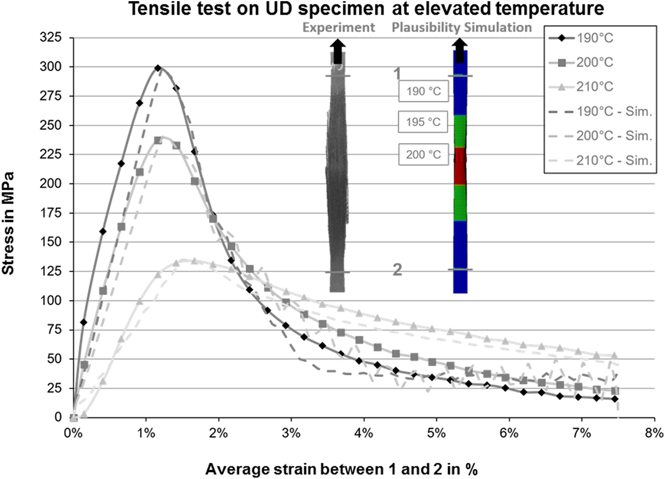
Comparison of tensile properties between simulation and experiment.
The shown stress versus strain curves in Figure 16 are generated with an even temperature assignment on the specimen in the simulation. In the calibration process of the material model, the evaluation of the tensile test is performed in the same way as in the experiment. As the temperature distribution that can influence the positioning of local strain is not measured in the experiment, the exact position in the simulation for the first calibration is ignored. Instead, a plausibility test was performed in which the assumption is made that the heating of the specimen in a hot air chamber is nonuniform, which is the case in reality due to the clamping conditions. The simulated specimen in Figure 16 is part of this plausibility test and shows an example of a specimen for a center temperature of 200°C. The simulation shows a localization of the deformation in the center. This result corresponds to the experimental one where the temperature gradient is unknown, but where the highest stretching also appears at the center of the specimen.
The shear behavior of the composite is controlled by the shell elements. When the element direction of the shells is defined at a 45° angle relative to the element direction of the beam elements as shown in Figure 15, then the tensile behavior of the elements corresponds to the shear behavior of the composite. This helps to enhance the stability of the model for very high levels of strain due to more acceptable levels of element distortions. Therefore, the material model calculates the shear behavior of the element based on the tensile parameters in the material model. The shear behavior of the shell elements is assigned the tensile behavior of the thermoplastic resin. As this property of the shell elements is a few orders of magnitude lower than the tensile properties of the beam elements, the shell element has no significant influence on the tensile behavior of the composite material.
The shear behavior of the organic sheet was characterized by a picture frame test (cf. Figure 17). In this test, the necessary shear stiffness response of a cross-shaped specimen against the deformation was measured. The direct output of this test is a force versus displacement curve (F-s). This F-s curve was converted into the stress–strain curve (τ-ε) that is given in the material model.
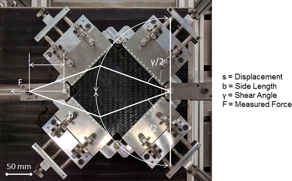
Characterization of in-plane shear behavior via the picture frame test.
First, the resulting shear angle has to be calculated by the crosshead displacement s and the frame side length b
The tension ε inside an element can then be simplified as in the following equation:

The shear stress τ results from the shear force FS and the sheared area A. This results as follows:
where l is the side length and t is the thickness of the specimen.
To calibrate a material model for the shear behavior, the picture frame test itself is remodeled in LS-DYNA®. In this example, the test is done for two different forming temperatures in the process temperature range. It is important to characterize the overall shear behavior of the composite and so the real lay-up (cf. Figure 2) is remodeled. To match the different tensile behavior in warp and weft direction, the calibration shown in Figure 16 is used. To compensate for the nonexistence of some real physical effects in the material model, a short fitting process is necessary. The outcome of this calibration process is shown in Figure 18.
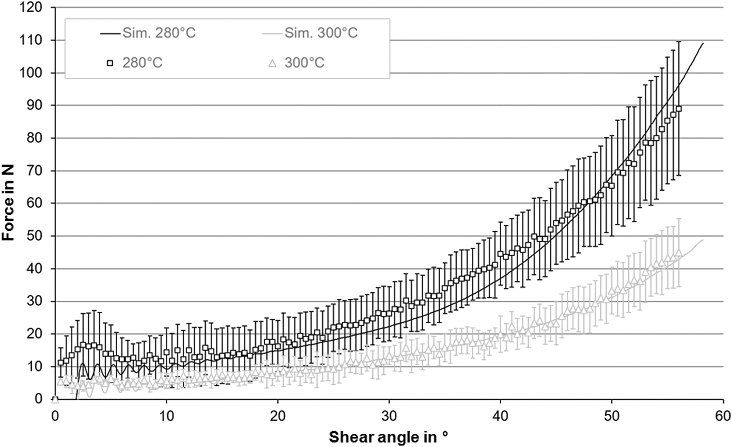
Comparison of the shear properties between simulation and experiment.
Verification of the FEM model
For the verification of the simulation approach, the deep-drawing experiment that was described in detail before and shown in Figure 10 is remodeled. The basis for the comparison is the experimental results carried out for two different forming depths and material thicknesses showing the local plastic deformation as already presented in Figure 13.
The deep-drawing experiment is remodeled exactly as it looks in the real experiment. In Figure 19, the complete set-up of the simulation is shown. The specimen itself is modeled as a type 1 and type 2 organic sheet, which is constrained with the tooling using the *constrained_extra_node_set keyword card. The only moving tool in the model is the punch with a temperature of 130°C that forms the specimen, heated-up to a temperature of 280°C, into a Ω-profile. The fringe-plot in the picture shows the effective axial strain in the beam element direction. This axial strain is compared with the experimental result. In the experimental analysis, the specimen is divided into 22 small areas where the local plastic strain is measured. In the simulated result, the same thing is done and the average strain in each area is then compared with the experiment (cf. Figure 20).
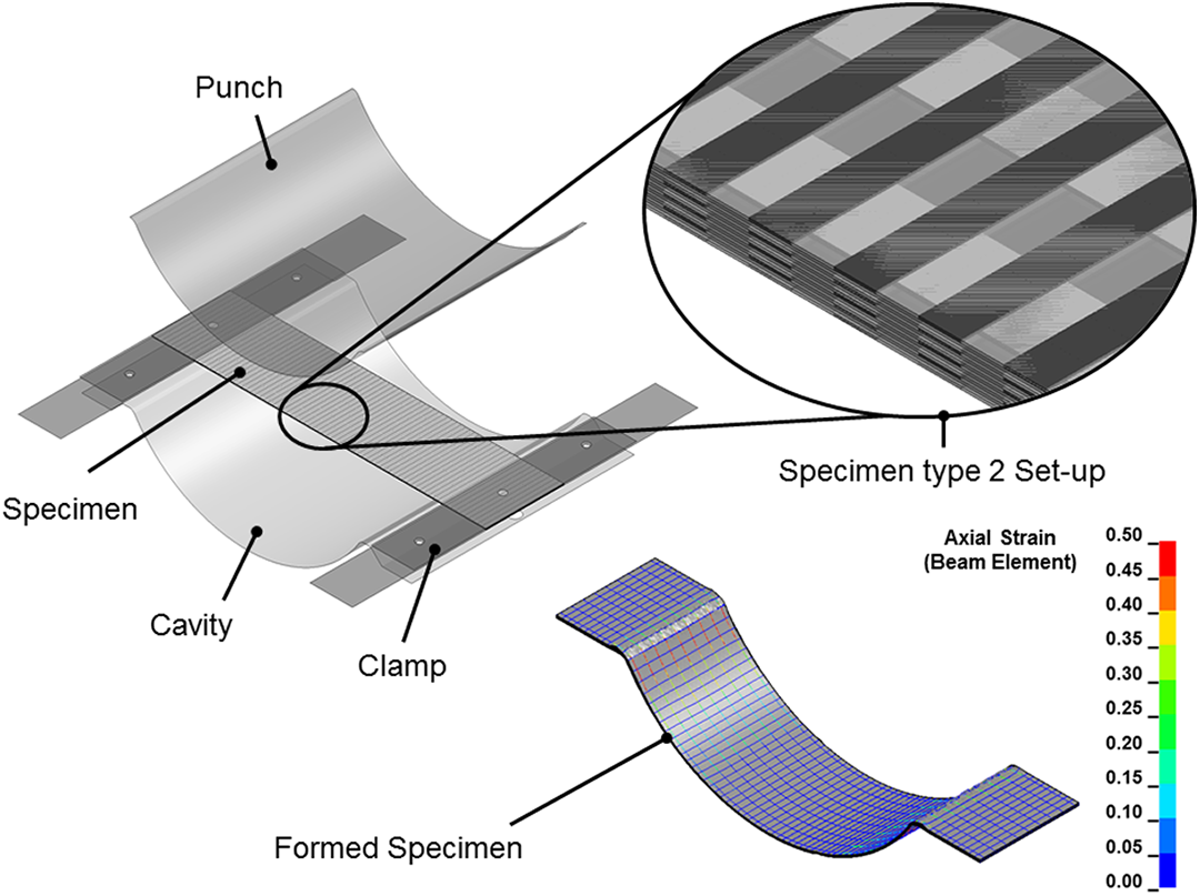
Simulation of the deep-drawing test.
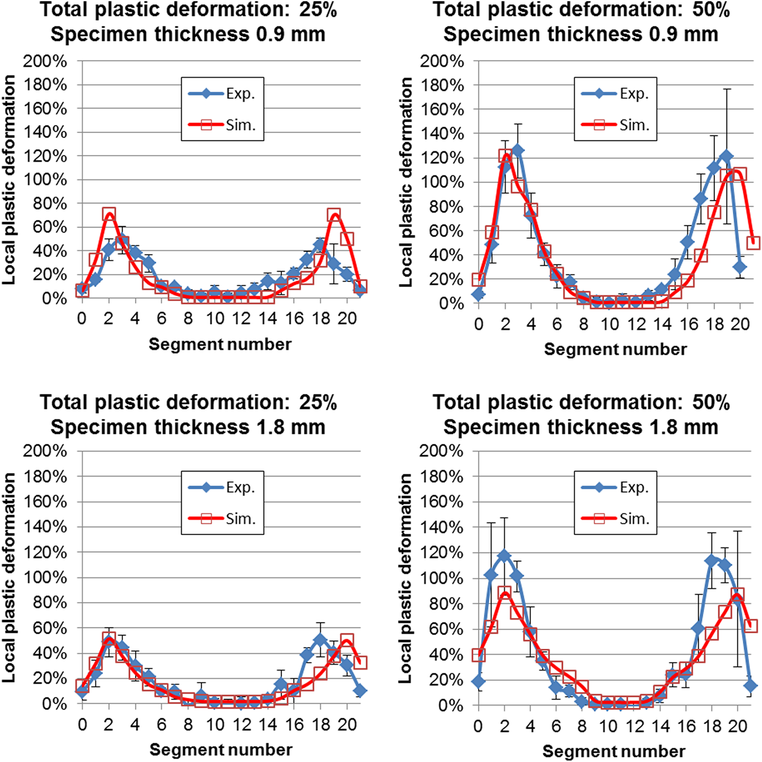
Comparison of the local plastic strain between experiment and simulation.
It should be noted that the axial strain shown in the simulation (see Figure 19) is the logarithmic strain as given by the software. In the experiment, the strain is calculated using the change in specimen length. So here the technical or engineering strain is used. For a correct comparison, the logarithmic strain of the simulation is recalculated into the technical strain using the formula shown as follows:

A comparison between experiment and simulation is presented in Figure 20 and shows excellent agreement in the local plastic deformation prediction for both levels of deformation and both specimen thicknesses. In all four cases, the simulation stays inside the standard deviation of the experiment. The slight shifting of the strain that can be seen in higher numbered areas is a result of the mesh and measurement resolution in the simulation in these highly deformed areas.
Summary
In this work, the development of rCF/PA6 staple fiber organic sheets has been described. In addition to the manufacturing, the mechanical characterization has been in focus to ensure the competitiveness of these novel semifinished products made of rCFs. Even though the tensile and bending properties are at a promising level (cf. Table 2), it was notable that the tensile values of specimens tested in warp direction were different to the ones tested in weft direction. This was the case although the laminate was symmetrically designed by providing a ratio of 2:1 (2 times 400 tex yarns in weft direction and one 800 tex yarn in warp direction).
The deep-drawing ability of staple fiber organic sheets has been investigated by pressing omega profiles in a thermoforming process using infrared heating. Results showed that an average plastic deformation of up to 50% of the material is possible based on the change in specimen’s length. Locally, more than 100% plastic deformation occurs and the SD of local plastic deformation increases correspondingly to the total plastic deformation. A fixed criterion as to when the plastic deformation is considered to be critical is yet to be defined. One approach could be to set minimum criteria for the mechanical properties on an absolute scale, for example, tensile strength and stiffness for the thinned-out areas of the part.
To provide a predictability of the deep-drawing behavior of staple fiber organic sheets, a finite element model has been developed in the software LS DYNA®, version 9.10. The model has been successfully used to validate the experimental results. Thanks to this material model, the local plastic deformations caused by the deep drawing can be predicted and final geometries of the parts can be anticipated. This is especially important for staple fiber organic sheets since the local thickness of the sheets will change during the deep-drawing process, which must be taken into account when the cavities of forming tools are designed. The focus of this work has been the development of a working simulation model. Based on these first results, there is the possibility of a more detailed sensibility and parameter study.
The results presented in this article can be used as a basis for the further development of staple fiber organic sheets. It is recommended by the authors to investigate the dependencies of textile manufacturing of yarns and NCF and their influence on staple fiber organic sheets. It is likely that optimization in precursors and semifinished products will lead to superior mechanical properties. The deep-drawing ability of staple fiber organic sheets shows great potential especially for hybrid TPFRPC processes and should be further developed in this direction.
Footnotes
Acknowledgements
The authors would like to thank Jörg Hehl and Stephan Baz from the Institute of Textile Technology and Process Engineering Denkendorf (ITV) and all other project partners for the great collaboration during the project “InTeKS.”
Funding
The author(s) disclosed receipt of the following financial support for the research, authorship, and/or publication of this article: The project “InTeKS” (Innovative Textile Structures Made Of Carbon Staple Fibers; Development of an innovative, plastically deformable organic sheet) received funding through the Bundesministerium für Wirtschaft und Energie. (Förderkennzeichen VP2088343TA4).