
Abstract
The aim of this research is to improve the impact strength of thermoplastic composites manufactured from recycled carbon fiber (rCF). For this purpose, the development of a novel multi-material, micro-scale hybridized and low-cost hybrid yarn by blending aramid fibers with rCF and polyamide 6 (PA 6) fibers through the processing route of carding, drawing and flyer spinning is reported in this paper. In addition, two other hybrid yarns were produced from rCF/PA 6 and aramid/PA 6 for comparison with the multi-material rCF/aramid/PA 6 hybrid yarn. Finally, the tensile, flexural and impact properties of composites based on the developed rCF/aramid/PA 6 multi-material hybrid yarn were compared with those of composites reinforced only with rCF and aramid fiber. The results of the Charpy impact test showed that the inclusion of 24 volume percentage aramid fiber increased the impact strength by 70% compared to the composite reinforced with rCF alone. The multi-material hybrid yarn consisting of rCF/aramid/PA 6 fibers shows good potential for designing a hybrid composite with tailored tensile, flexural and impact resistant properties.
Keywords
Carbon fiber-reinforced composites (CFRPs) are widely used in high-tech industries such as aerospace, automotive and wind energy due to their outstanding mechanical, corrosion resistance and lightweight properties.1–4 With the increased use of CFRPs, recycled carbon fiber (rCF) is generated in the form of discontinuous fiber lengths at various stages of fabric manufacturing in the form of production offcuts, selvedges and bobbin ends. In addition, rCF is recovered from end-of-life composite components through an additional process step (e.g. the commonly used pyrolysis technique). For environmental reasons, CF waste or rCF cannot be disposed of by conventional waste management techniques (landfill or incineration). Furthermore, in Europe, it is a requirement that a minimum of 85% of disposed vehicles can be recycled (EU 2000/53/EC). Since the production of CFRP is also extremely energy and cost intensive, the re-use of low-cost rCF of discontinuous lengths in a second life cycle is not only ecologically but also economically viable. This will make CFRP components more competitive for wider use, particularly in automotive applications. On the one hand, fossil fuels can be saved when using conventional combustion engines. On the other hand, the range of electric vehicles based on lightweight construction can be significantly increased, leading to a broader implementation of electromobility. 5 Therefore, the re-use of rCF in CFRPs for automotive parts is attracting interest from academia and industry. 6
Injection-molded parts and randomly oriented nonwovens used in the remanufacture of CFRPs are among the industrially established solutions for the production of semi-finished products from rCF. However, the strength of composites based on moldings and nonwovens made from rCF waste is low due to several factors: low fiber length efficiency due to low fiber orientation, damage during processing and low fiber content in composites.7,8 As alternatives to injection molding and nonwoven technologies, other technologies for the manufacturing of semi-finished products from rCF with high orientation include the High Performance Discontinuous Fibre (HiPerDiF) method to produce aligned mats9–11; tape, 12 organic sheet 13 and hybrid yarn6,14–20 manufacturing techniques based on drawn slivers. By enhancing fiber orientation, the tensile strength of CFRPs consisting of rCF can be improved significantly.20,21 However, CFRPs are characterized by low impact resistance due to the brittle and stiff behavior and low elongation 22 of carbon fiber, which leads to sudden failure in the composite structure. 23 Therefore, in order to improve the impact properties or increase the ductility of composites composed of rCF, the concept of fiber hybridization is inevitable, 5 where carbon fiber is combined with relatively low modulus and high elongation fibers, such as glass and aramid fiber. The presence of the higher elongation glass/aramid fiber would reduce the probability of failure of the lower elongation carbon fiber, resulting in higher elongation and impact resistance of hybrid composites.
In the fiber hybridization approach, the manufacturing of fiber hybrid composite structures (i.e. a composite in which at least two types of fibers are used to reinforce a common matrix) can be achieved by a layer-by-layer approach (macroscale),24–27 within a layer by alternating reinforcing yarns through a yarn-by-yarn approach (meso-scale)22,28 or by intermingled hybrids by randomly and intensively mixing two fiber types (micro-scale) in the same ply. 29 However, regardless of the mixing category, the level of mixing/dispersion is one of most important parameters influencing the mechanical properties of hybrid composites. 30
The literature review shows that the majority of reported investigations address fiber hybrid composites achieved by a layer-by-layer approach (macroscale) or by a yarn-by-yarn approach (meso-scale) consisting of continuous filament yarns. The laminating sequence in the case of the layer-by-layer approach governs the mechanical properties of (especially tensile, flexural and impact) of hybrid composites. 5 Placing glass/aramid fiber fabric layers in the exterior and carbon fiber fabric layers in the interior results in higher tensile strength and ultimate tensile strain in comparison to carbon fiber fabric layers being positioned in the exterior and glass/aramid fiber fabric layers in the interior. 26 In Czél and Wisnom, 31 it is reported that the thinner the central carbon fiber layer or the lower the carbon fiber to glass fiber ratio, the lower the extent of delamination between the layers reinforced with different fibers. Flexural properties of hybrid composites can be influenced to a great extent by changing the lay-up, as the longitudinal stress at the neutral line is zero, but increases when moving away from that line. 5 In Song, 26 it was shown that composite specimens in which carbon and glass fiber layers are laminated alternately and four-ply have the highest flexural strength of 696 MPa, while that of specimens in which glass fiber fabric layers in the exterior and carbon fiber fabric layers in the interior type have the lowest value of 498 MPa. In the opposite condition with the carbon layer on the top, the bending strengths were low. Like tensile strength, the laminating composites of alternating four layers of carbon and glass fiber also showed the best property in a bending test. In terms of impact resistance, the layer positioning of interlayer fiber hybrid composites is a crucial aspect. The penetration impact resistance can be improved by placing carbon fiber in the middle of symmetric layers and glass fibers on the outside.32,33 The higher failure strain of glass fiber can be attributed to a delay in the onset of the damage due to impact. It was shown by Pincheira et al. 22 that aramid and CFRPs hybridized by a yarn-by-yarn approach (meso-scale) resulted in an improvement in impact strength but a decrease in compressive and tensile strength and reduced stiffness.
In contrast, experimental studies on discontinuous micro-scale fiber hybrid composites are sparse. In Longana et al., 34 different investigations on the development of highly oriented discontinuous hybrid fibrous structure from reclaimed CF produced by using the HiPerDiF method have been reported. In Hasan et al., 8 novel multi-material hybrid yarns with a core–sheath structure were developed from a mix of waste CF and polyamide 6 (PA 6) fiber combined with continuous glass filaments in the core and PA 6 fiber in the sheath. An increase of 18.4% in impact strength can be achieved in hybrid composites if the total fiber volume content is identical to that of non-hybrid composites.
Within our previous studies, the development of hybrid yarns based on flyer17,20,35 and DREF14,19 spinning and the mechanical properties of composites produced from these hybrid yarns made from rCF and PA 6 are described. In Hasan et al., 14 it is shown that composites made from such hybrid yarns consisting of waste CF/rCF and PA 6 possess approximately 85% of the tensile strength of composites consisting of virgin filament tow. These rCF-based composites offer an enormous potential for use in load-bearing structures compared to the achievable composite strengths of injection-molded components and nonwovens. However, the impact properties of composites manufactured from rCF of defined lengths are still relatively low to be used for impact resistant components. 8 As a result, there is a strong need of to improve the impact resistance of composites based on rCF.
Therefore, in order to improve the impact strength of composites made from rCF, a novel approach to the production of fiber hybrid composites based on multi-material, micro-scale hybridized and low-cost hybrid yarns is reported in this paper. One of the main objectives of this work is to reveal the textile technological aspects required for the development of multi-material hybrid yarns by blending aramid fibers with rCF and PA 6 fibers through the processing route of carding, drawing and flyer spinning. Furthermore, the properties of hybrid yarn were characterized in terms of tensile strength, fiber orientation and level of mixing. Finally, the tensile, flexural and impact properties of composites based on the developed multi-material hybrid yarn consisting of rCF, aramid and PA 6 were compared with those of composites reinforced with rCF and aramid fiber only.
Experimental methodology
Materials
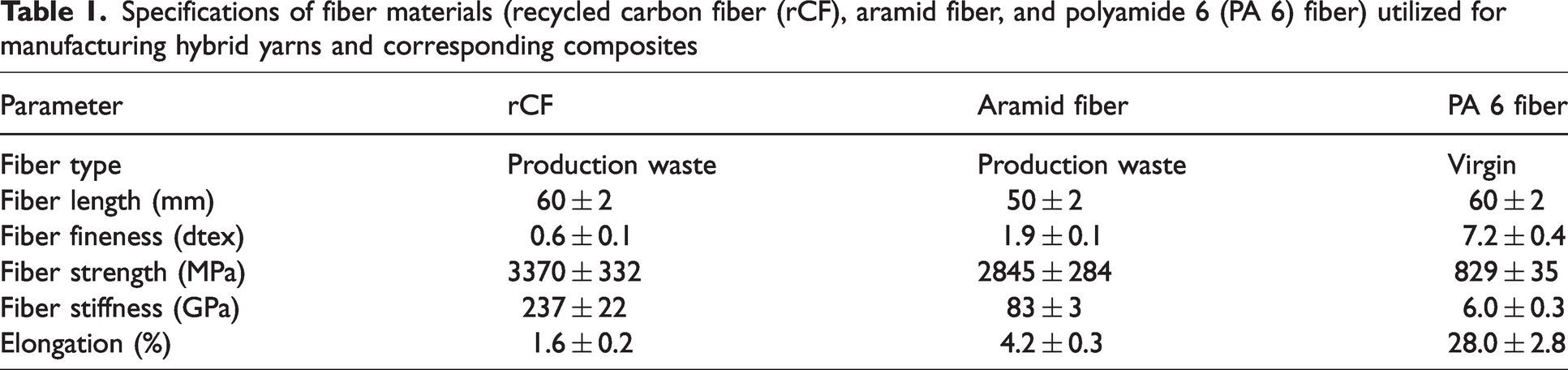
In this study, rCF, aramid and crimped PA 6 fibers were used as raw materials for the development of hybrid yarns. The rCF and aramid fibers were obtained from production waste. After consolidation, the PA 6 fibers inherently mixed with rCF and/or aramid fibers act as the matrix in the composites. Table 1 shows the main characteristics of different fibers used for the development of hybrid yarns. The individual fiber fineness was determined by the vibration method using a Vibromat ME (Textechno Herbert Stein GmbH & Co. KG, Germany) following DIN EN ISO 1973. The tensile behavior of the fibers, including maximum tensile strength, modulus and elongation at break, was determined using a FAVIMAT tensile tester (Textechno Herbert Stein GmbH & Co. KG, Germany) following DIN EN ISO 5079.
Specifications of fiber materials (recycled carbon fiber (rCF), aramid fiber, and polyamide 6 (PA 6) fiber) utilized for manufacturing hybrid yarns and corresponding composites
Development of hybrid yarns
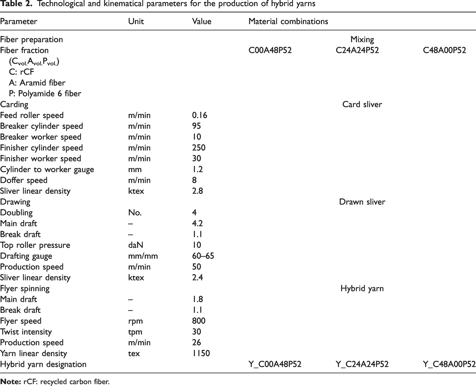
The process chain used for the development of hybrid yarns in this work consisted of fiber preparation, carding, drawing and flyer spinning, as shown in the Figure 1. In the fiber preparation process, a homogeneous blending of fibers for a further carding process was carried out. For this purpose, the following three types of blended fibers with the desired fiber content were prepared through a fiber opener for the final production of three hybrid yarns (Table 2):
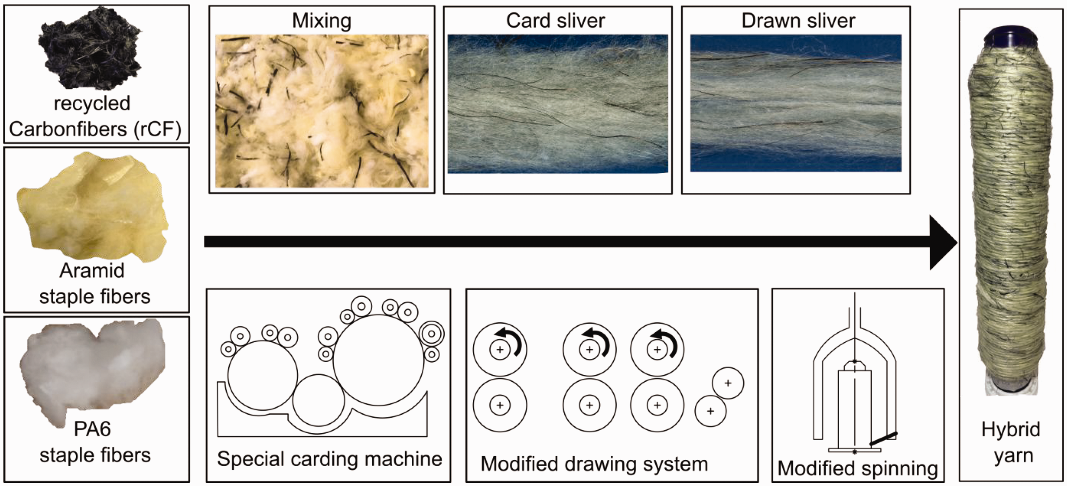
The process chain for hybrid yarn development. PA 6: polyamide 6.
Technological and kinematical parameters for the production of hybrid yarns
rCF/PA 6 fibers: 48/52 (volume %);
aramid/PA 6 fibers: 48/52 (volume %);
rCF/Aramid/PA 6 fibers: 24/24/52 (volume %).
The rCF/PA 6 and aramid/PA 6 hybrid yarns were produced for comparison with the multi-material rCF/aramid/PA 6 hybrid yarn.
The pre-opened and hybridized fiber blend was then processed on a special carding machine to produce a partially oriented card sliver with minimal fiber damage. The carding machine was modified and optimized specially for the gentle processing of brittle rCF reported by Khurshid et al. 36 In addition, the effect of the roller spacing between the cylinder and worker, which is the main carding zone, on fiber shortening is analyzed in this work. For this purpose, investigations were carried out by varying the roller spacing between the cylinder and worker at 0.5, 1 and 1.2 mm. The results showed that 0.5 mm roller spacing between the cylinder and worker led to a fine opening of rCF. However, this narrow distance in the carding zone reduced the length of the rCF by up to 50%. When the roller spacing between the cylinder and worker is smaller, the shear force acting on the rCF is higher. As a result, the shortening of the rCF length during carding is greater at smaller cylinder to worker spacing due to the brittleness of the rCF. The mean fiber length of the brittle rCF during processing was measured by using the image analysis method.37,38
In contrast, a wider adjustment of the carding zone (2 mm) produced a hybrid sliver without fiber opening. The investigations revealed that the optimum configuration in the carding zone (1.2 mm) produced rCF with better fiber opening and limited fiber damage (up to 10%). Furthermore, the results showed that the length of the rCF remains around 54 ± 2 mm after the carding process, while the length of the aramid fiber remained undamaged due to the higher flexibility of aramid fiber compared to that of the rCF.
In the next step, hybrid card slivers were processed on the modified draw frame to improve hybridization (micro-scale) and fiber orientation. The details of the draw frame modification are described by Khurshid et al. 39 For this purpose, four ends of the card slivers were fed to the drawing machine and a drawn sliver of 2.4 ktex (i.e. 2.4 g/m) was produced at a delivery rate of 50 m/min. It was found that the drawing process had no significant effect on the fiber length reduction of the rCF and aramid fibers. Finally, the hybrid yarn with a linear density of 1150 tex and a twist intensity of 30 twists per meter (tpm) was spun on the special flyer machine. The technical parameters of the carding, drawing and spinning process, including a longitudinal view of the slivers and hybrid yarns, are given in Table 2.
Production of unidirectional thermoplastic composites
To produce a unidirectional (UD) thermoplastic composite from the hybrid yarn, the hybrid yarn was wound on a metal frame with a uniform winding density. Consolidation was then carried out by using a laboratory-scale press machine (P 300 PV from COLLIN Lab & Pilot Solutions GmbH, Germany). The optimized consolidation parameters of temperature (280°C) and pressure (1.5 MPa) were used to develop UD thermoplastic composites. Figure 2 shows the process steps to develop a composite based on a hybrid yarn structure. The composites made from the hybrid yarns Y_C00A48P52, Y_C24A24P52 and Y_C48A00P52 are designated as Com_C00A48P52, Com_C24A24P52 and Com_C48A00P52, respectively. Com_C00A48P52 and Com_C48A00P52 are reinforced only by aramid and rCF fiber, respectively, whereas Com_C24A24P52 is a hybrid composite as it is reinforced by rCF and aramid fiber.
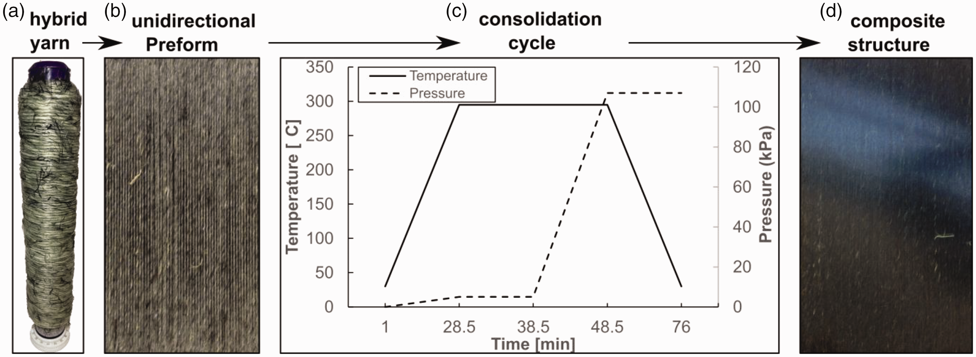
Fabrication of unidirectional (UD) thermoplastic composites: (a) hybrid yarn; (b) UD preform; (c) consolidation cycle; (d) composite structure.
Characterizations
Hybrid yarns
The structure of the hybrid yarn and the angle of the inclined fibers in the yarn structure were determined from the yarn profile. For this purpose, the scanned image of the hybrid yarn from optical and laser triangulation methods was used to investigate the structure. Later, the scanned image of the hybrid yarn was imported into OrientationJ software 40 to determine the angle of the inclined fibers in the yarn structure.
Composites
The tensile properties of the UD thermoplastic composites made from hybrid yarns were measured according to the standard test method DIN EN ISO 527-5. For this purpose, composite specimens with a length of 250 mm, a width of 15 mm and a thickness of 1 mm were placed in a Zwick-type Z100 tensile tester (Zwick GmbH and Co., Germany). To determine the flexural properties of the composites, specimens with dimensions of 80 × 15 × 2 mm3 (length × width × thickness) were subjected to a four-point bending test according to DIN EN ISO 14125: 98. The test speed was 2 mm/min for both tensile and flexural tests. The Charpy impact test was performed on a CEAST 9050 pendulum impact tester (Instron GmbH, Germany) to measure the impact properties of the composites using composite specimens with dimensions of 40 ×15 × 2 mm3. To determine the porosity content of the fabricated composite specimens, the specimens were evaluated using the infiltration technique according to the guidelines of ASTM D2734-09. The weight of the specimen was determined both before and after ignition. The process temperature has been set to 350°C. For this purpose, an oven of the model Controller B170, manufactured by Fa. Nabertherm (Germany), was used. In addition, a balance, model LSZ200C, manufactured by Fa. PCE Group (Germany), was used to determine the sample weights. Furthermore, in order to obtain information on the breaking pattern, microscopic images of the fracture zone are analyzed after tensile, flexural and impact testing.
Results and discussion
Hybrid yarn properties
Scanned images of the multi-material hybrid yarn Y_C24A24P52 taken by the optical method and the laser triangulation method are shown in Figures 3(a) and (b), respectively. The yarn profile shows that few fibers or fiber bundles protrude from the yarn surface. The degree of protruding fibers (hairiness) is an indirect indicator of damaged fibers present in the yarn structure. The yarn profile also shows that the developed hybrid yarn is uniform and does not contain significant thick and thin places.
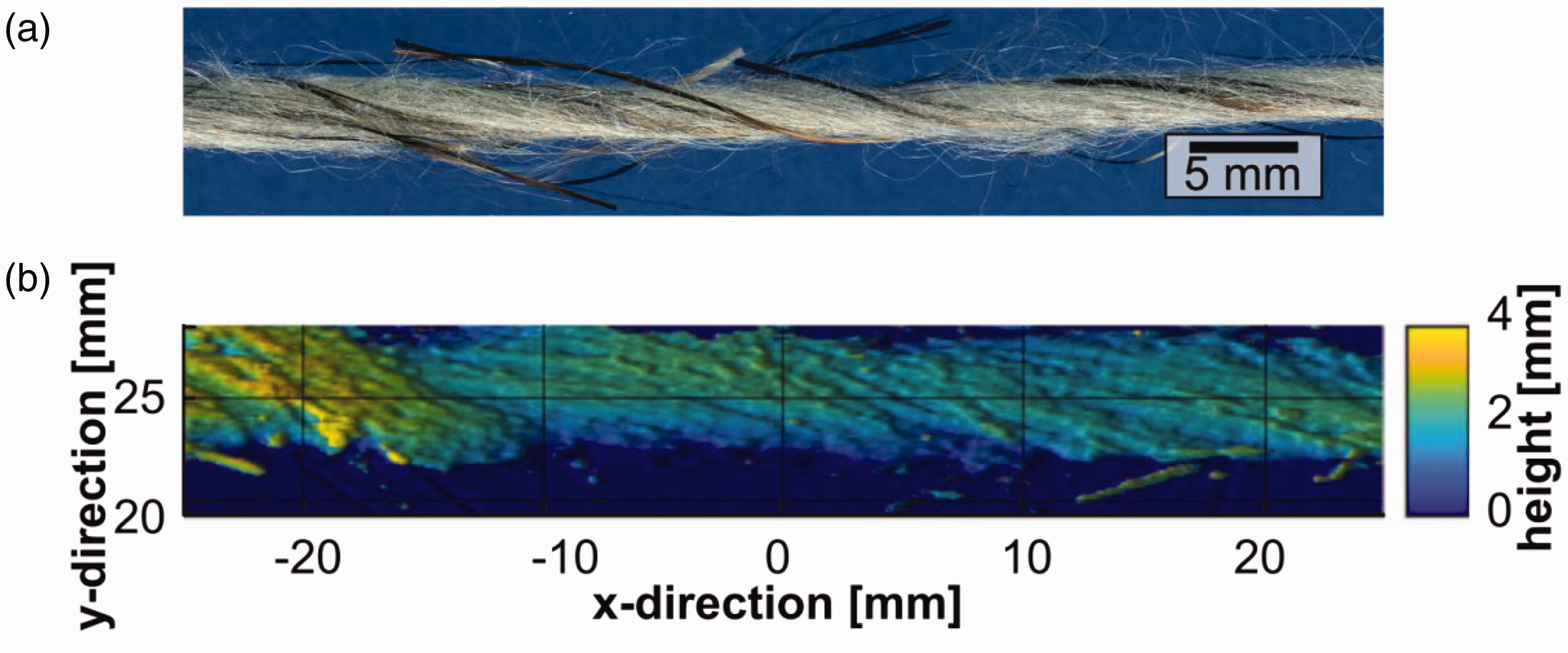
Hybrid yarn profile taken by the (a) optical and (b) laser triangulation methods.
In addition, the angle of the inclined fibers assessed from the yarn profile is found to be around 7.5°, which is in a similar range to the theoretical value reported by Valença et al. 28 This value indicates that the fibers bound in the yarn structure are close to UD. The angle of the inclined fibers in the staple yarn structure depends on the twist intensity and increases with increasing twist. In this study, the twist intensity of the hybrid yarns was 30 tpm. Therefore, by reducing the twist intensity, the fiber orientation in the yarn structure can be further improved.
The microscopic view of the Y_C24A24P52 hybrid yarn cross-section shown in Figure 4 clearly indicates that the rCF, aramid and PA 6 fibers are homogeneously distributed in the cross-section of the yarn. This homogeneous distribution confirms the micro-scale hybridization in the yarn structure and ensures uniform consolidation during the composite manufacturing process.
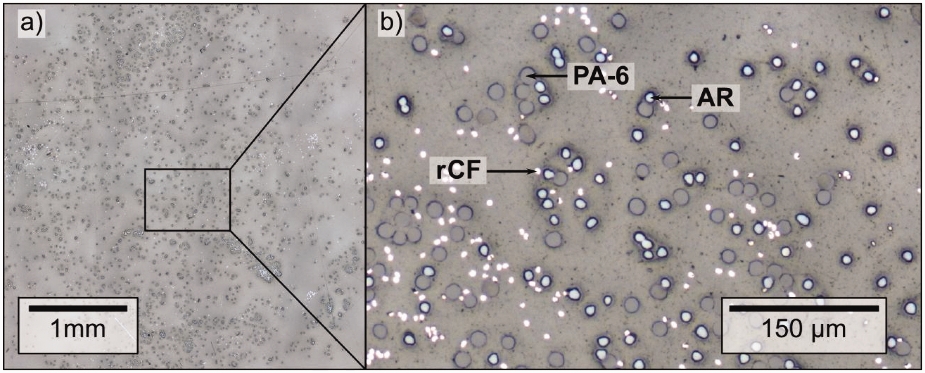
Microscopic view of the developed multi-material hybrid yarn (Y_C24A24P52) structure from recycled carbon fiber (rCF), aramid (AR) and polyamide 6 (PA 6) fibers.
Composite properties
Figure 5 shows microscopic cross-sectional images of the composite samples. The spatial arrangement of the reinforcing fibers shows a good uniformity across all sample groups. In particular, Figure 5(b) shows the high dispersion degree achieved within the Com_C24A24P52 configuration. Throughout the specimens, certain regions (Figures 5(a) and (c)) exhibit a relatively higher proportion of matrix material. Further research is needed to fully understand why matrix-rich areas form, particularly with regard to the consolidation parameters applied during the pressing process.
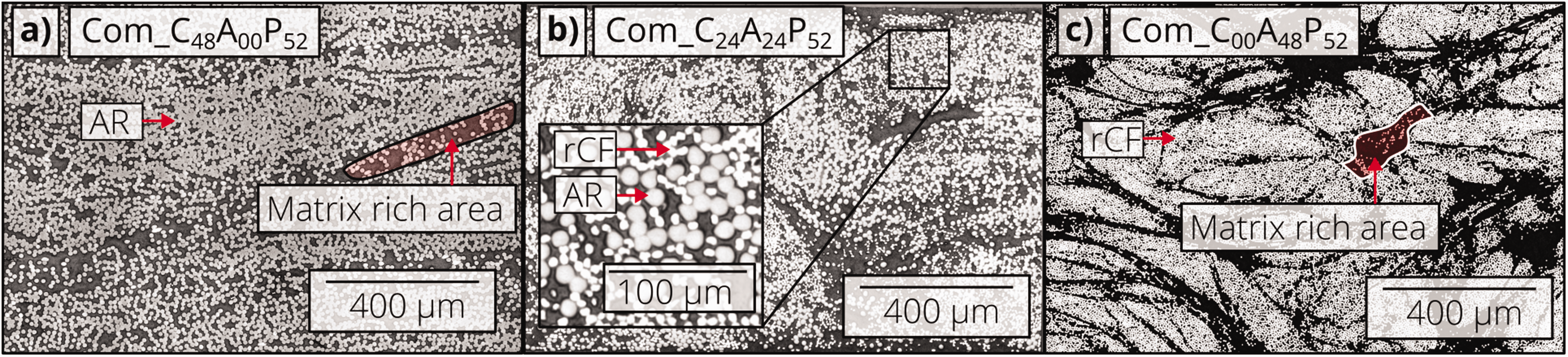
Microscopic images of composite cross-sections: (a) Com_C48A00P52; (b) Com_C24A24P52; (c) Com_C00A48P52. rCF: recycled carbon fiber.
The stress elongation curves of the tensile and four-point bending tests are illustrated in Figure 6. The results show that increasing aramid fiber content in the composite specimens leads to a significant decrease in mechanical properties under tensile and bending loading. For both tensile and bending strength and Young's and bending moduli, the composite reinforced only with carbon fiber has the highest measured values. This results from the higher strengths and stiffnesses of the carbon fiber compared to the aramid fibers. On the other hand, the elongation at break of the composite reinforced only with rCF has the lowest elongation at break. The elongation at break of the hybrid composite (Com_C24A24P52) is 62.5% higher than that of the rCF-reinforced composite (Com_C48A00P52).
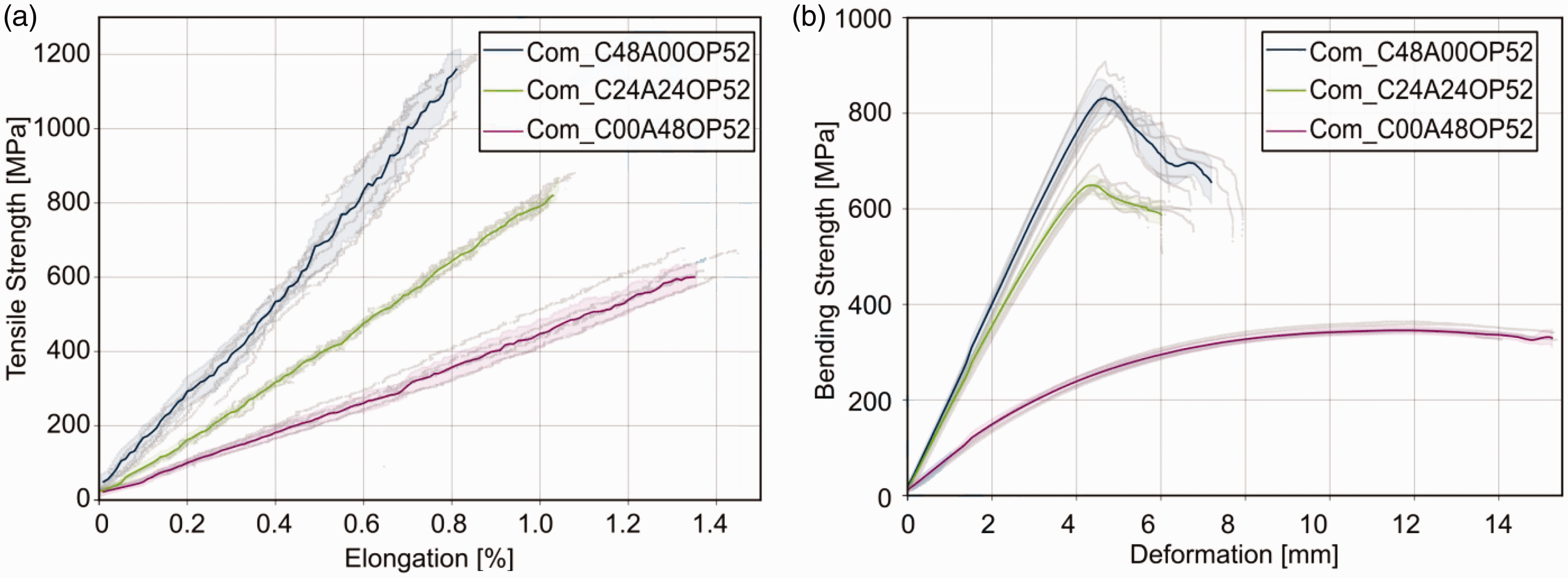
Stress elongation curves of the tensile (a) and four-point bending test (b) of composites produced from different hybrid yarns.
The average tensile strength and Young’s modulus of UD composites based on developed hybrid yarns are shown in Figure 7(a). The composite reinforced solely with rCF (Com_C48A00P52) has the highest tensile strength of 1180 ± 50 MPa and Young’s modulus of 85 ± 14 GPa. In contrast, the composite reinforced solely with aramid fiber has the lowest tensile strength of 630 ± 40 MPa and Young’s modulus of 27 ± 2 GPa. In the case of hybrid composite Com_C24A24P52 reinforced with rCF and aramid fiber, the tensile strength of 870 ± 30 MPa and Young’s modulus of 53 ± 2 GPa were achieved. The bending strength and modulus of the composite specimens are presented in Figure 7(b). The results show the same tendency as that found in the case of tensile tests. The highest bending strength (860 ± 34 MPa) and modulus (98 ± 6 GPa) were obtained from the Com_C48A00P52 composite. The flexural strength and flexural modulus of Com_C24A24P52 hybrid composite are 670 ± 20 MPa and 60 ± 1 GPa, respectively. These can be attributed the properties and fraction of rCF. Therefore, the tensile and bending properties of composites can be significantly influenced by changing the rCF content of the composite.
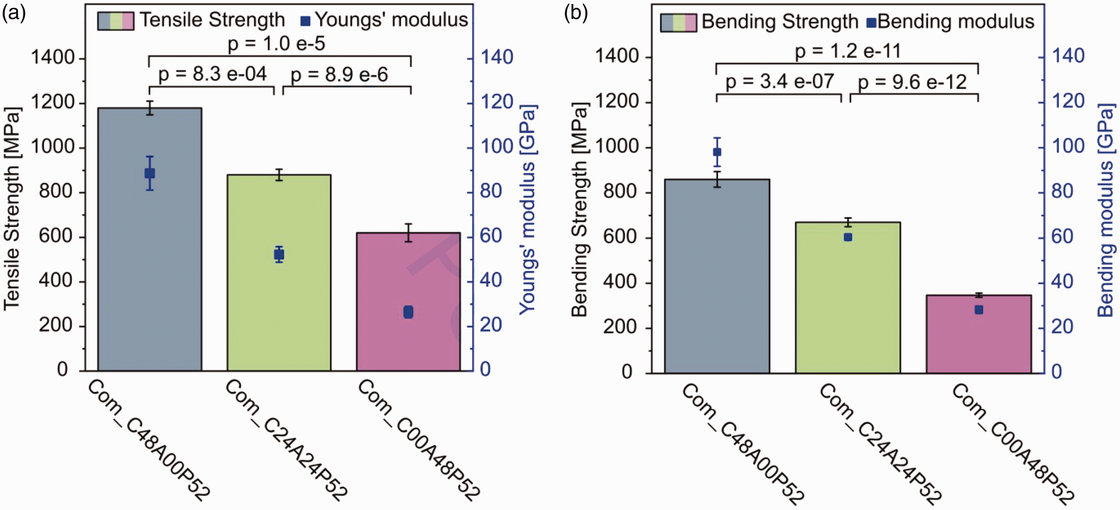
Tensile (a) and bending properties (b) of composites produced from different hybrid yarns.
Figure 8 shows the impact toughness of composites made from the three different hybrid yarns developed in this study. The results show that the toughness of the composites based on hybrid yarns increases with increasing aramid fiber content. The impact toughness of the Com_C24A24P52 hybrid composite is 101 ± 18 kJ/m2, which is about 70% higher than that of the Com_C48A00P52 composite. This is due to the aramid fibers, which are made from aromatic polyamide and have higher elongation with excellent energy absorption properties.
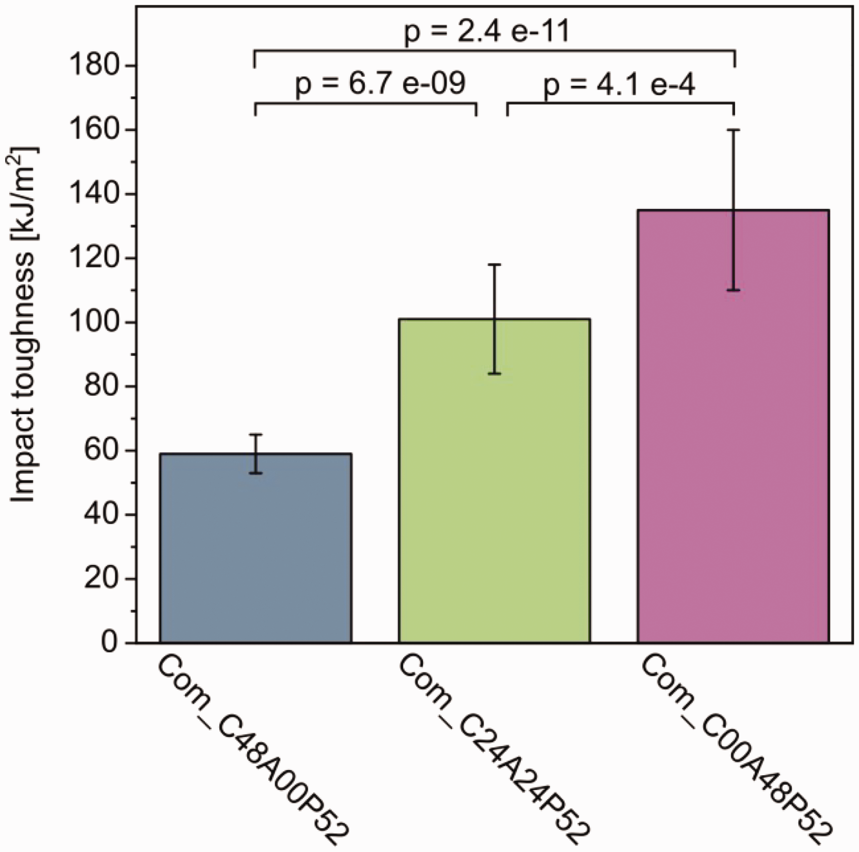
Impact properties of composites based on hybrid yarns.
From images of the specimens, after tensile, bending and Charpy impact testing (Figure 9), it can be observed that all Com_C48A00P52 specimens break generally in a brittle pattern. In the case of tensile testing Com_C48A00P52 specimens, it clearly shows the large number of broken composite surfaces leading to a more unstable and brittle failure of the composite. Particularly in the case of bending and Charpy tests, the specimens break into two halves, while numerous hybrid composite specimens (Com_C24A24P52) are still adhering to one another because of the elongated aramid fiber in the breaking point. The assessment of porosity content within the composite materials resulted in the following outcomes for individual specimens: for the composite Com_C48A00P52, the determined porosity was measured at 2.9 ± 1.1%. Similarly, the Com_C24A24P52 specimen exhibited a porosity level of 2 ± 0.7%. In addition, the porosity content of the Com_C00A48P52 specimen was found to be 1.9 ± 0.4%. These measured porosity values are notably low, leading to the conclusion that any potential influence on the mechanical properties of the materials can be considered as non-significant.
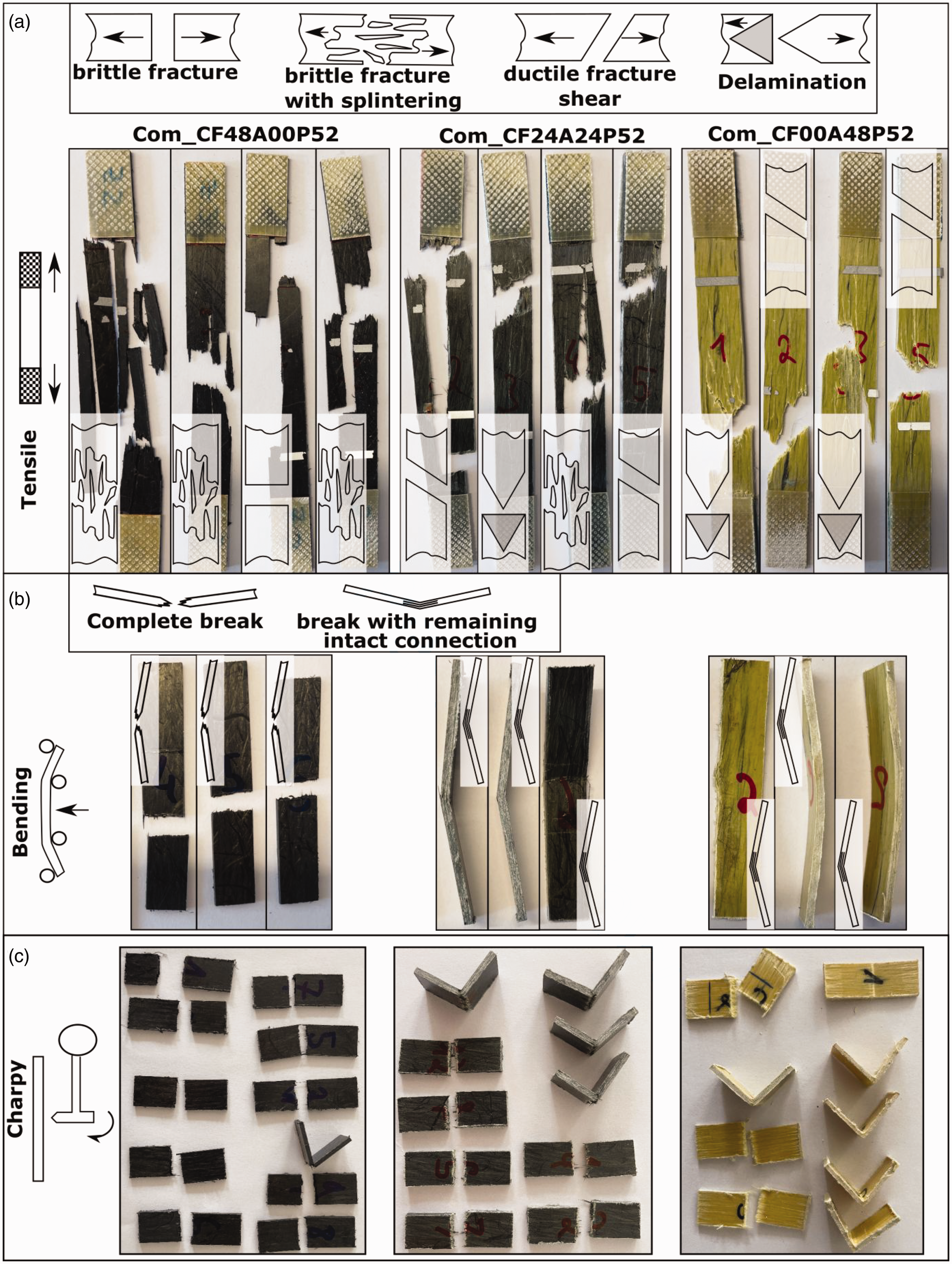
Breaking pattern of different composites after tensile, bending and Charpy impact tests.
Figure 10 shows scanning electron images of the Charpy test specimens. In Figures 10(a), (b) and (d), it can be seen that the fracture edges of the rCF have a straight fracture edge, indicating a brittle sudden fracture. In contrast, Figures 10(b), (c) and (e) show a deformation of the aramid fiber ends. This indicates a ductile fracture behavior of the aramid fibers. The high impact strength of the specimens containing aramid fibers could be due to the ductile fracture behavior of these fibers.
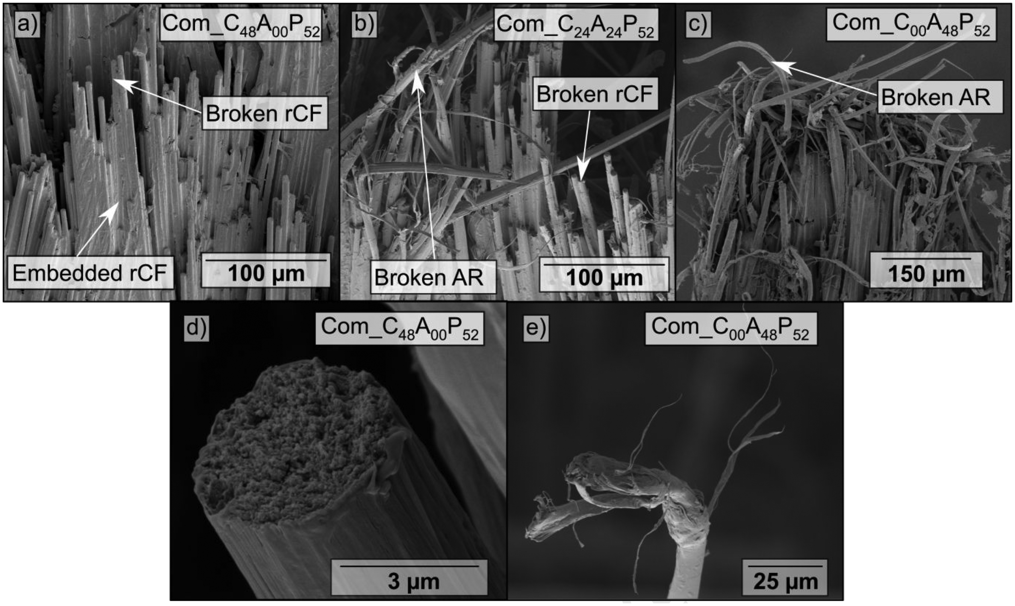
Scanning electron microscope images of the Charpy impact tested composites: (a) Com_C48A00P52; (b) Com_C24A24P52; (c) Com_C00A48P52; (d) straight breaking edge of the recycled carbon fiber (rCF); (e) aramid (AR) fibers deformed at the fiber end.
An overview of the effect of mixing aramid fiber with rCF on the mechanical properties of composites can be seen in Figure 11. It shows that the tensile, flexural and impact resistant properties of the hybrid composite reinforced by rCF and aramid fiber can be customized compared to the composite reinforced only with rCF.
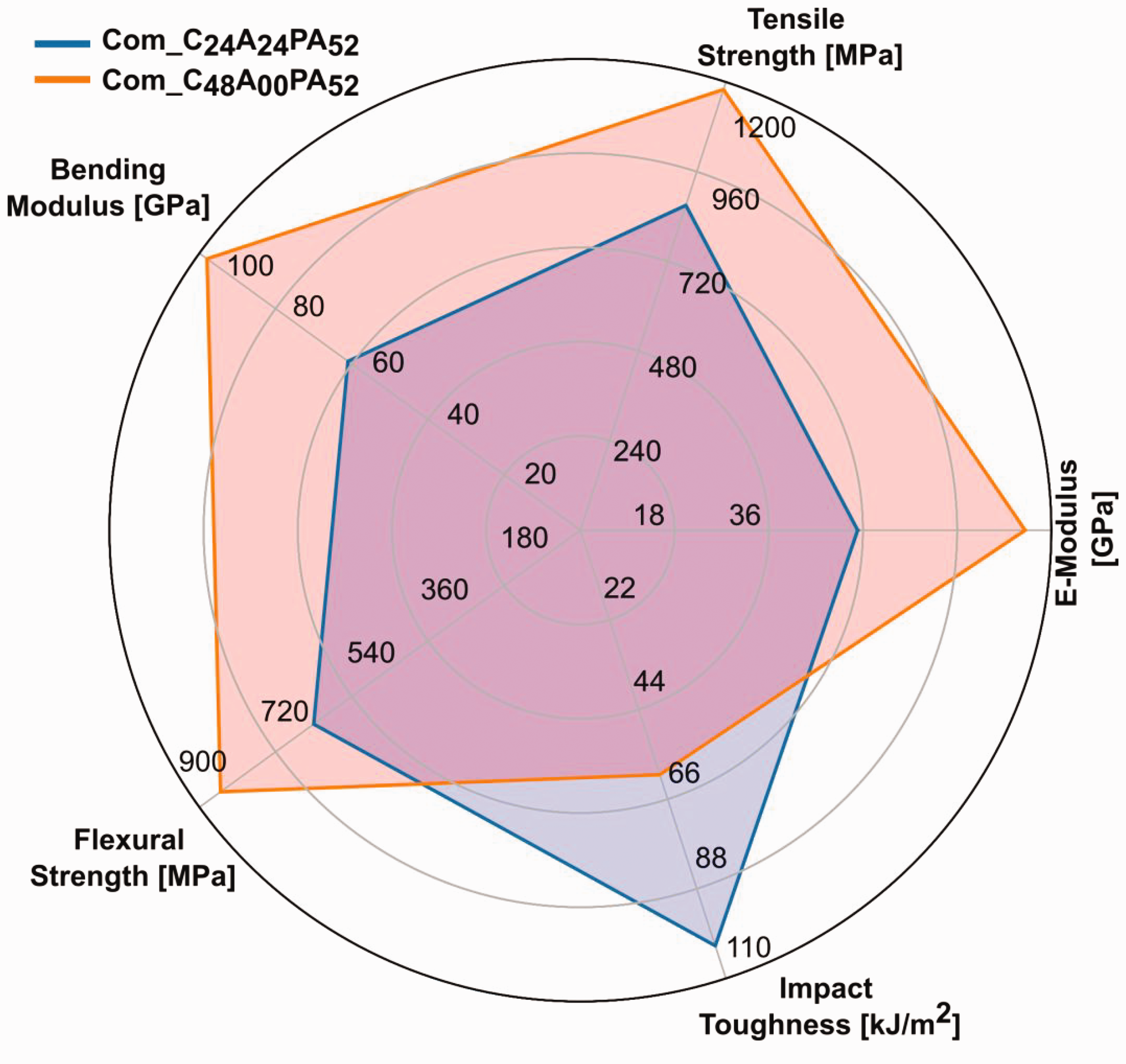
Radar chart with the properties of composites based on hybrid yarns.
Conclusion
In this paper, the development of a cost-efficient, micro-scale hybridized and well-oriented multi-material hybrid yarn structure from rCF/staple aramid/PA 6 fibers for impact resistant thermoplastic composites has been reported. The tensile, flexural and Charpy impact properties of the hybrid composite developed from the multi-material hybrid yarn structure consisting of rCF/aramid/PA 6 fibers are compared with those of composites made from hybrid yarn consisting of rCF/PA 6 and aramid/PA 6 fibers, respectively. The results of Charpy impact testing suggest that the impact strength increases by 70% due to the inclusion of 24 volume percentage aramid fiber compared to the composite reinforced solely with rCF. However, a compromise in terms of the tensile strength and Young’s modulus of the composite has to be made. In this case, the tensile strength and Young’s modulus of the hybrid composite are around 25 and 41%, respectively, which are lower compared to those of the composite reinforced solely with rCF. However, the elongation at break of the hybrid composite after tensile testing is found to be significantly higher (62.5%) than that of the CF-PA 6 composite.
It can be concluded that hybrid yarn technology is fully capable of developing cost-efficient composite structures with improved impact resistant properties by altering the composition of carbon and aramid fibers such that they meet the requirements of impact-loaded structural applications, in particular for automotive applications and wind turbine blades. In addition, hybrid composites based on the multi-material hybrid yarn do not require optimization of the lay-up configuration, which is usually required for hybrid composites, especially those based on a layer-by-layer (macroscale) approach. Other advantages include the ease of manufacture of these hybrid structures and their suitability for mass production of thermoplastic composites based on rCF. However, the comparison of the impact behavior due to the different degree of dispersion remains to be understood.
Footnotes
Declaration of conflicting interests
The authors declared no potential conflicts of interest with respect to the research, authorship, and/or publication of this article.
Funding
The authors disclosed receipt of the following financial support for the research, authorship and/or publication of this article: This work presents parts of the results from the research program of the Industrial Collaborative Research (IGF-21004 BR/1) and the German Research Foundation, DFG – 407164652 (Project-CH 174/46-1) at the TUD Dresden University of Technology, Germany. The article processing charge (APC) were funded by the joint publication funds of TU Dresden, including the Carl Gustav Carus Faculty of Medicine and SLUB Dresden, as well as the Open Access Publication Funding of the DFG.