
Abstract
In this article, detailed procedure for the development of polylactic acid (PLA), hydroxyapatite (HAp) and chitosan (CS)-based biocompatible functional prototype has been outlined by using three-dimensional (3D) printing as a case study. The biocompatible composite-based feedstock filament (comprising of PLA-HAp-CS) has been prepared through twin-screw extruder (TSE) for open-source fused deposition modelling (FDM)-based 3D printer. This case study provides two-stage multifactor optimization: (a) for preparation of feedstock filament on TSE and (b) 3D printing on FDM based upon tensile and flexural samples. The results of study suggest that the best settings of input parameters for TSE are barrel temperature of 190°C, screw speed of 140 r/min and dead weight of 12 kg. Further, the optimized settings for FDM are layer thickness of 0.2 mm, deposition angle of 30/45° and infill density of 100%. The results have been supported by scanning electron microscopic analysis.
Introduction
The use of foreign materials to be used as implants within or outside the human body is not new. There are reports of more than 2000 years old that indicate the replacement of bone material in order to repair seriously damaged tissues. 1 Hydroxyapatite (HAp), being chemically and structurally similar to the inorganic component of bone, enamel and dentin, has received considerable attention from the biologists and biomaterial scientists. It has been successfully used as bone fillers, aesthetic restorative, coating of orthopaedic implants, filler of inorganic/polymer composites, cell culture carriers and so on. It is, however, worth mentioning that the application of pure HAp is being limited due to its brittleness. In recent years, the development of bioactive ceramic–polymer composites commonly known as bio-analogue has gained a phenomenal impetus in the orthopaedic field for their bone analogue design as well as good biological and mechanical performances to meet specific clinical requirements. 2 –4 The idea is to use a ceramic–polymer composite material that can develop a considerable anisotropic character by means of adequate orientation techniques reinforced with a ceramic that simultaneously assures the mechanical reinforcement and the bioactive character of the implant. 4 –7
Natural biopolymers have received much attention in the fields of orthopaedic and other biomedical applications, due to their excellent biocompatibility and biodegradability. 5,8 CS (chitosan; poly-1,4-D-glucosamine), a partially deacetylate form of chitin, is structurally similar to glycosaminoglycan and has many desirable properties for tissue engineering (TE) applications. 9
Advances in polymer chemistry and the development of new alloys in modern metallurgy during the second half of the 20th century gave rise to a variety of materials for reconstruction and replacement of some tissues inside and outside the human body. In the case of ceramic materials, the development of modern technologies has led to new materials with chemical, physical and mechanical properties that make them an excellent choice for applications in dental and orthopaedic implants. 10 –12 The ‘biocompatibility’ of a biomaterial is defined as their ability to successfully fulfil a specific application, with an appropriate response of the host. In other words, biocompatibility means more than the fact that a material is not harmful in the body. A material is ‘not biocompatible’ if it is toxic and/or if it causes the death of surrounding tissues. 11,13 A biocompatible material may be considered for medical applications if there is no reaction with tissue and the material is stable for indefinite periods of time. 14 –16
Additive manufacturing (AM) has been used by many researchers in recent past for TE application. 17 –19 HAp is artificially like the mineral segment of bones and hard tissues in well-evolved creatures. HAp is similar to structural and chemical resemblance to teeth and bone due to its key inorganic phosphate. 20 –23 It is a most prominent biomaterial, which has use as teeth, or bone substitution, regeneration and hard tissue repair. HAp is generally prepared/obtained from eggshells. Generally, HAp made scaffolds/inserts are biocompatible and bioactive as well as open porous structure that is best suitable for bone regeneration. HAp decomposition temperature is very high, about 800–1200°C (depends upon its stoichiometry) that is why it is best suitable for developing biomedical scaffolds.
The literature review reveals that some studies have reported the use of HAp and CS as reinforcement in biocompatible polymers. 24 But hitherto very less has been reported on multifactor optimization for mechanical properties while reinforcement of biocompatible polymer (polylactic acid (PLA)) with HAp and CS for fabrication of scaffolds/implants in TE applications. So, in this case study, functional prototypes have been prepared by reinforcement of biocompatible polymer PLA with HAp and CS in different proportions. For systematic analysis of the functional prototype prepared, standard tests (namely, melt flow index (MFI) as per ASTM D 1238, continuous flow ability (visual inspection), thermal analysis based upon differential scanning calorimeter (DSC), tensile properties on universal tensile tester (UTT) as per ASTM 638, dimensional accuracy (based upon ISO3611-1978) and scanning electron microscopic (SEM) analysis for best composition/proportion of reinforcement) were performed for fabrication of feedstock filaments on twin-screw extruder (TSE) in first stage. Second, for preparation of biocompatible and biodegradable scaffolds, fused deposition modelling (FDM) parameters have been optimized using multifactor optimization. Figure 1 shows stepwise procedure for fabrication/development of biodegradable, biocompatible and bioactive scaffolds using HAp, PLA and CS.
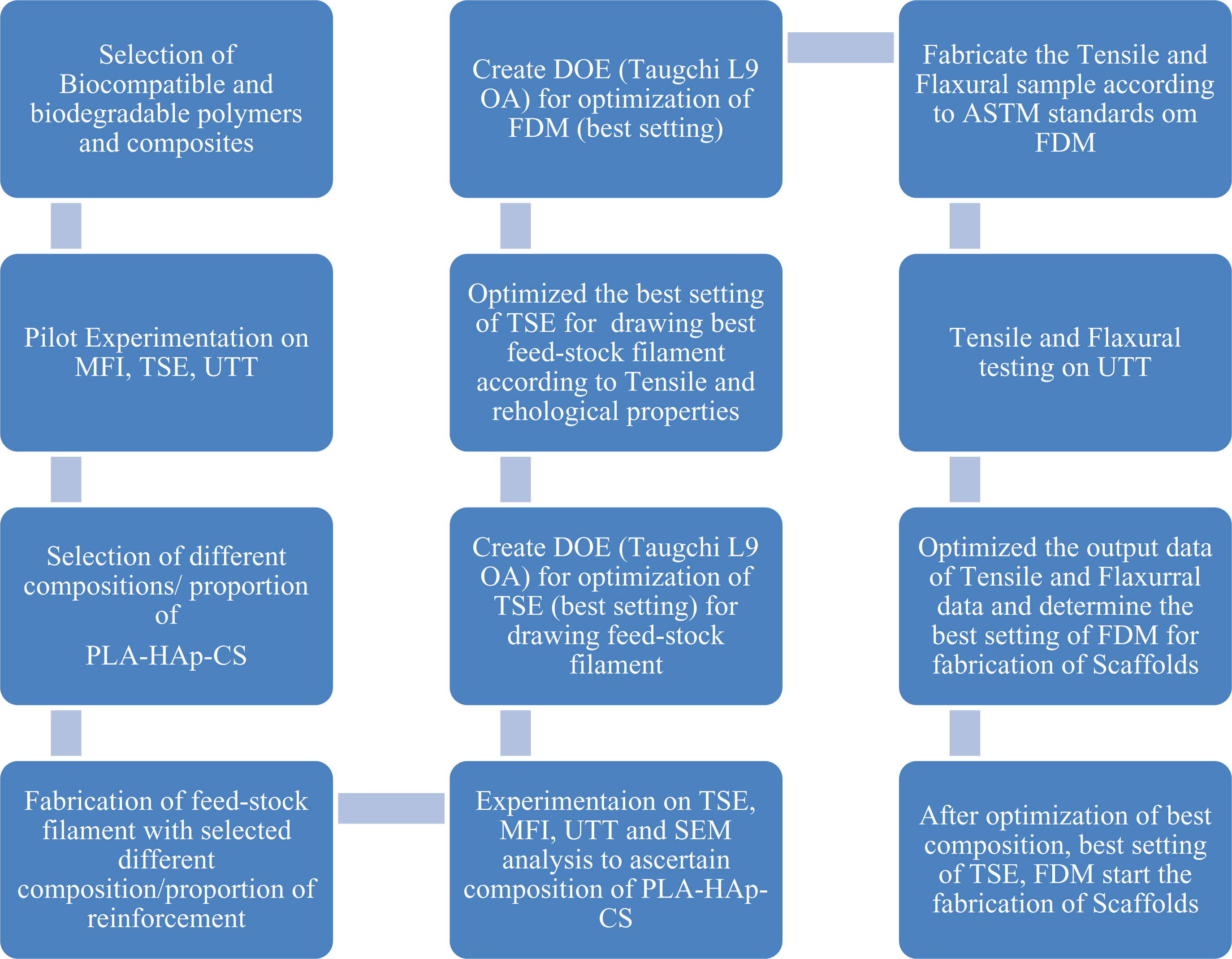
Stepwise procedure for fabrication of biodegradable scaffolds using HAp, CS, and PLA.
Experimentation
In the pilot experimentation, an effort has been made to determine the best suitable material composition (which is biodegradable, bioactive, biocompatible and non-toxic) for fabrication/development of biocompatible and degradable biomedical scaffold/implants/inserts in bone engineering/TE applications. Initially, different compositions/proportions of PLA reinforced with biocompatible and bioactive composites (HAp and CS) were selected (see Table 1).
Selected different material composition of PLA-HAp-CS.
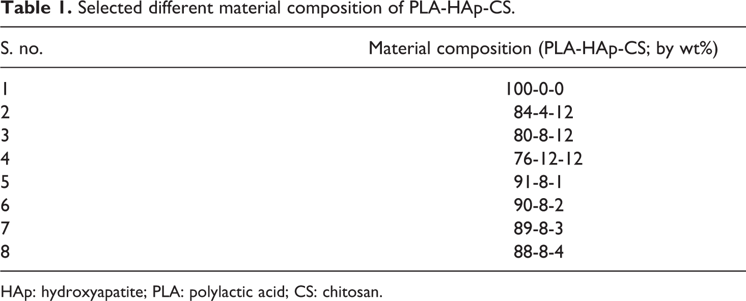
HAp: hydroxyapatite; PLA: polylactic acid; CS: chitosan.
Based upon Table 1, experimental study was conducted to understand MFI and flow continuity for wire drawing (see Table 2).
Rheological and flow ability of different compositions of PLA-HAp-CS.
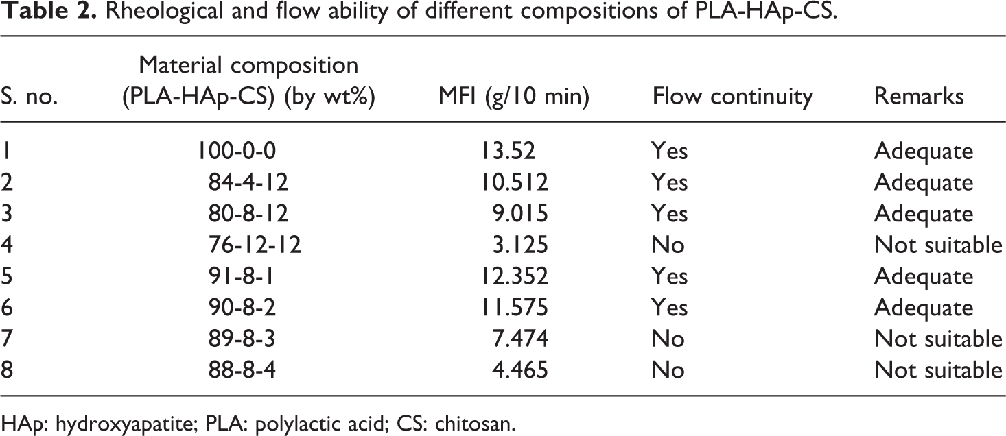
HAp: hydroxyapatite; PLA: polylactic acid; CS: chitosan.
Based upon observations in Table 2, it has been concluded that five of eight compositions are suitable according to continuous flow ability test. Here, one composition (at s. no. 1) is without reinforcement of HAp and CS in PLA that is used for comparison purpose only and needs to be neglected because pure PLA is not used for the development of scaffolds. Hence, finally four samples were selected for further testing (i.e. s. no. 2, 3, 5 and 6). Further based upon observations in Table 2, 04 material compositions/proportions were selected to analyse dimensional and tensile properties (see Table 3).
Dimensional and tensile properties with different compositions of PLA-HAp-CS.
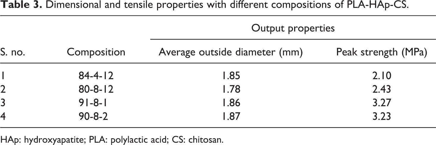
HAp: hydroxyapatite; PLA: polylactic acid; CS: chitosan.
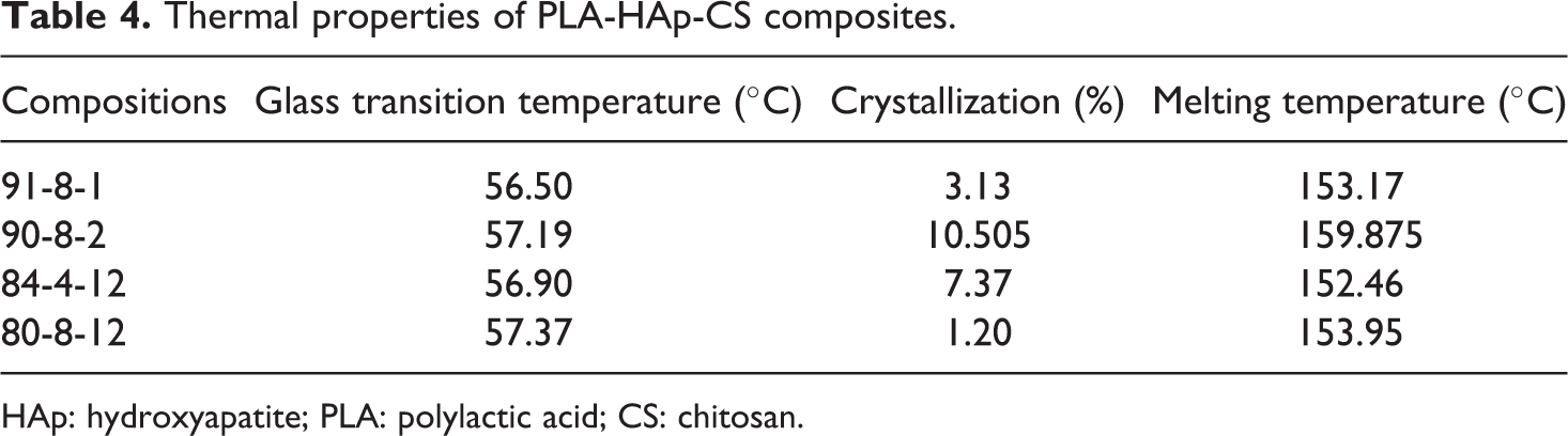
After preparation of feedstock filament, dimensional accuracy was checked by Mitutoyo’s absolute digimatic micrometer (as per ISO3611-1978) having accuracy up to 0.001 mm and peak strength was checked in tensile testing on UTT (as per ASTM 638). As observed from Table 3, all four feedstock filaments (with different composition/proportion) outside diameters are in acceptable range; however, two compositions, that is, 91-8-1 and 90-8-2 were further shortlisted from better peak strength view point. In order to counter verify the suitability of selected compositions for feedstock filament, thermal analysis for four compositions was carried out on DSC (Model DSC3; by Mettler Toledo (Greifensee, Switzerland); with STARe SW 14.00) software in nitrogen gas environment. In this experimentation, glass transition temperature (°C), crystallization (%) and melting temperature (°C) were determined. Figure 2 and Table 4 show the results of thermal analysis for selected four compositions of PLA-HAp-CS.
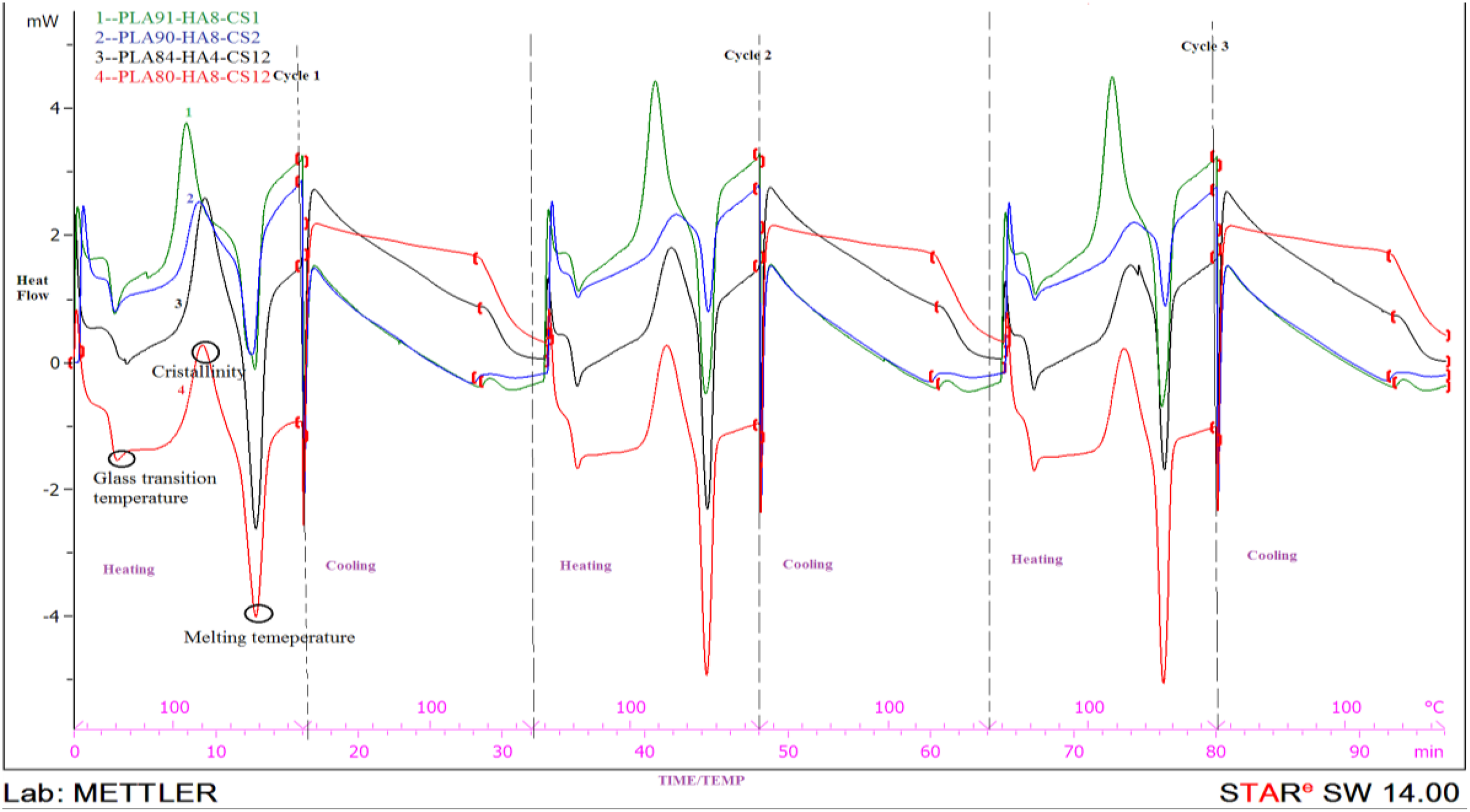
Thermal analysis graph of four compositions of materials on DSC.
Thermal properties of PLA-HAp-CS composites.
HAp: hydroxyapatite; PLA: polylactic acid; CS: chitosan.
It has been observed that glass transition temperature and melting temperature data have no significant difference (see Table 4), so all the feedstock filament wires are suitable. But in the case of crystallinity (%), the compositions 91-8-1 and 80-8-12 (PLA-HAp-CS) are better solutions. Finally, based upon Tables 3 and 4, PLA-HAp-CS composition as 91-8-1 (by weight percentage) has been judicially selected (by giving more weight age to peak strength) for fabrication of feedstock filaments by using TSE.
For this study, commercial make HAAKE Mini CTW (Dieselstr, Karlsruhe, Germany) has been used. The feedstock filament wires were prepared according to Taguchi L9 (33) OA. For TSE process, the input parameters selected are temperature of TSE barrel, revolution of screw and applied dead weight. After parametric optimizations of TSE and open-source FDM, functional prototypes have been printed. For open-source FDM, the input parameters selected are layer thickness of single layer of sample (for tensile and flexural samples), deposition angle of polymer material and fill density of sample. Figure 3 shows three-dimensional (3D) view of open-source FDM.
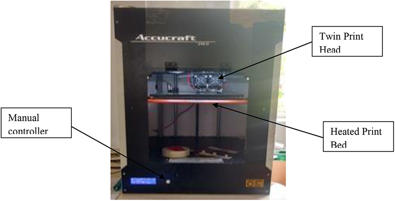
3D view of open-source FDM (volumetric space of 250 mm3).
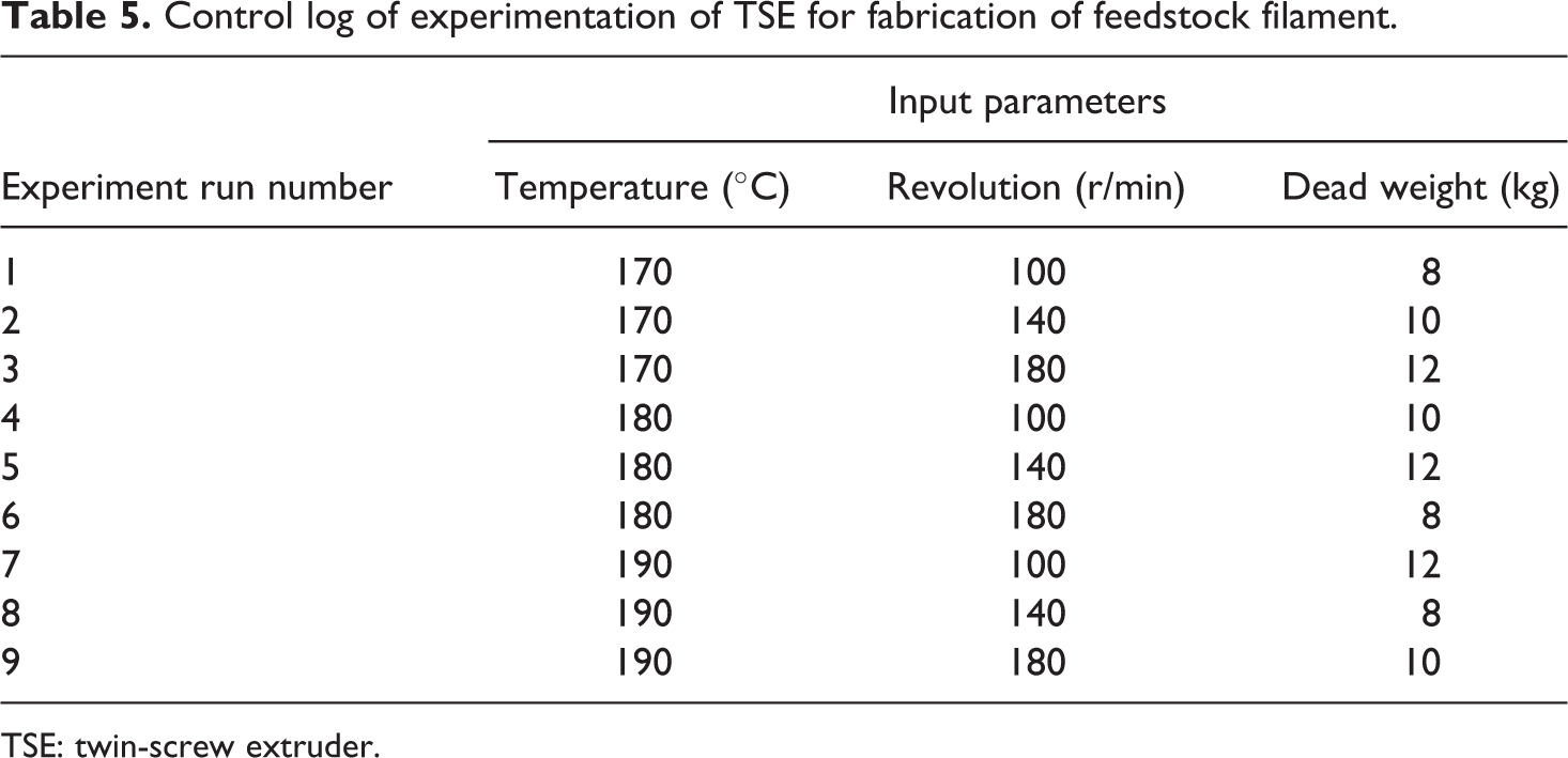
Tables 5 and 6 show the control log of experimentation based on TaguchiL9 (33) OA which was nine runs of experimentation for fabrication of feedstock of filaments on TSE and for fabrication of samples (tensile and flexural samples) on open-source FDM, respectively.
Control log of experimentation of TSE for fabrication of feedstock filament.
TSE: twin-screw extruder.
Control log of experimentation of FDM for fabrication of tensile and flexural samples.
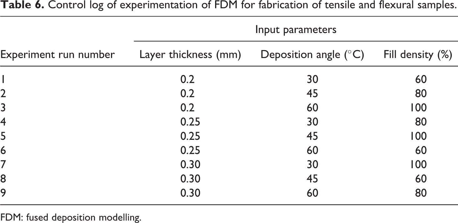
FDM: fused deposition modelling.
Results and discussion
Optimization of TSE setting for fabrication of feedstock filament (multifactor optimization of TSE)
After determining the best composition of PLA-HAp-CS materials, next step was to determine the best setting of TSE for preparation/drawing best feedstock filament according to tensile strength. The feedstock filament has been prepared according to Taguchi L9 (33) OA. Based upon Table 5, 09 sets of feedstock filament have been prepared and total 27 (9 × 3) experiments were conducted to reduce the effect of human variations and environmental effect and so on. Table 7 shows the output parameters of feedstock filaments with signal to noise ratio (SNRA) of all feedstock filaments (based upon Table 5).
Output data of feedstock filament of PLA-HAp-CS (91-8-1) on TSE.
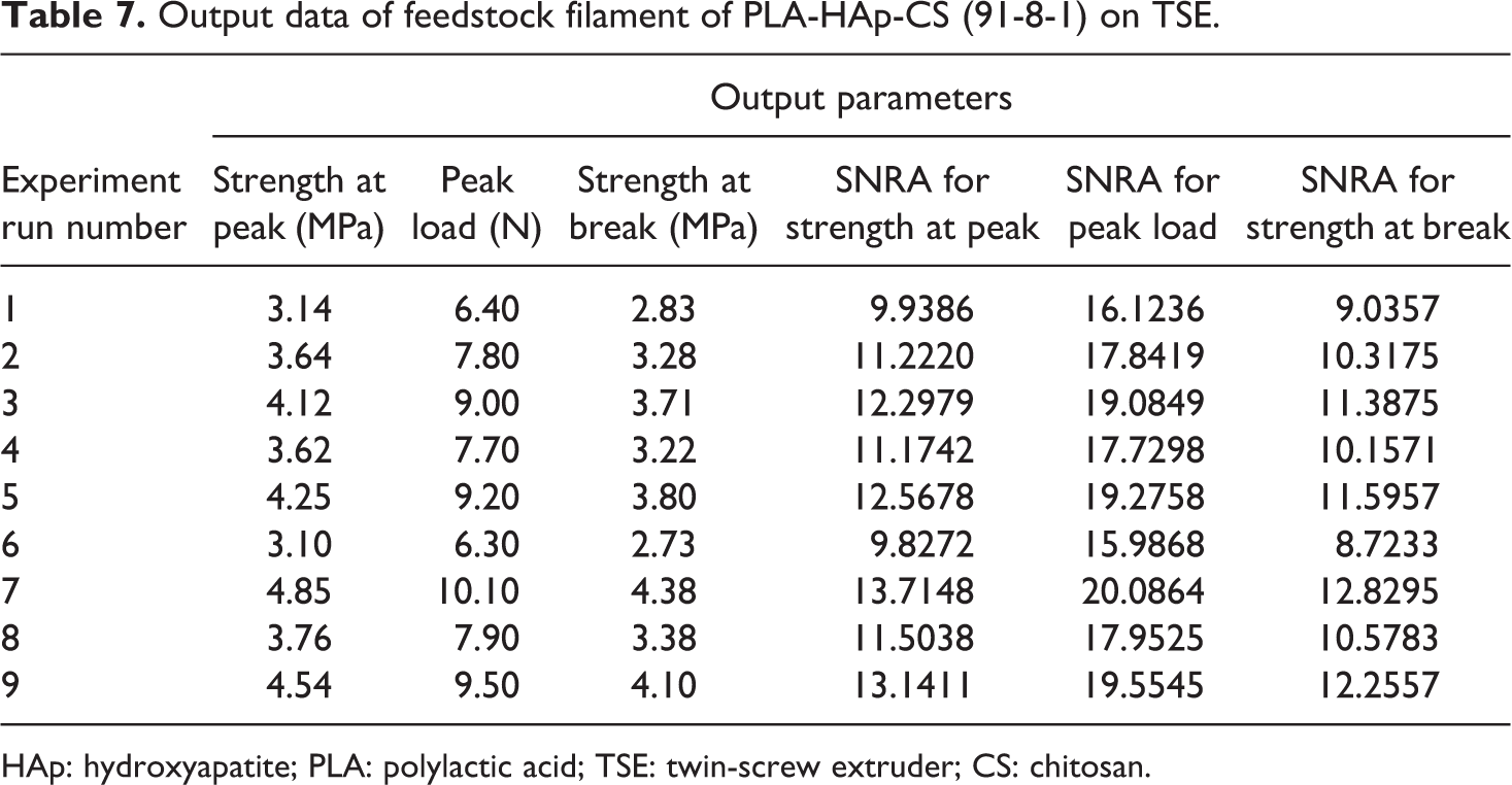
HAp: hydroxyapatite; PLA: polylactic acid; TSE: twin-screw extruder; CS: chitosan.
Based upon Table 7, multifactor optimization has been done on Minitab 17.00 (software) with output parameters as strength at peak, peak load and strength at break. Table 8 shows the lower and higher value of SNRA of each output parameter and given equally weighted.
Response optimizer for multifactor optimization for TSE.
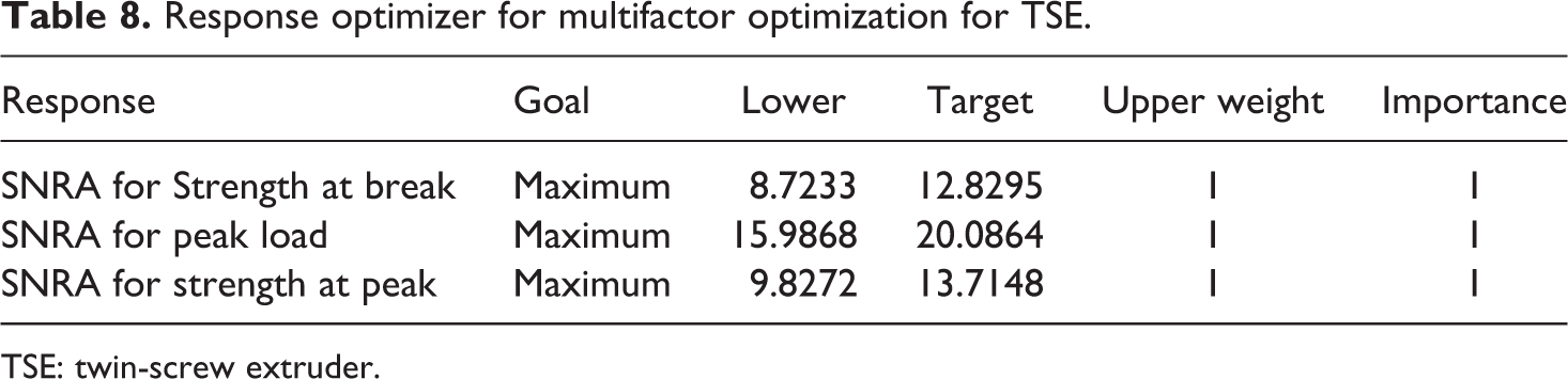
TSE: twin-screw extruder.
Based upon Table 8, Table 9 shows the output of multifactor optimization with best settings obtained by using SNRA.
Output of multifactor optimization with best setting obtained with best SNRA.
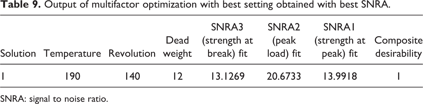
SNRA: signal to noise ratio.
Figure 4 and Table 9 outline that the best setting for fabrication of feedstock filaments of composition 91-8-1 (PLA-HAp-CS) is at 190°C barrel temperature with 140 r/min of screw speed and 12 kg of dead weight. Figure 5 shows the SEM image of feedstock filament prepared at proposed settings according to Table 9. It has been observed from SEM-based photomicrographs that feedstock filament has open porous structure, which is useful for cell growth and TE applications.
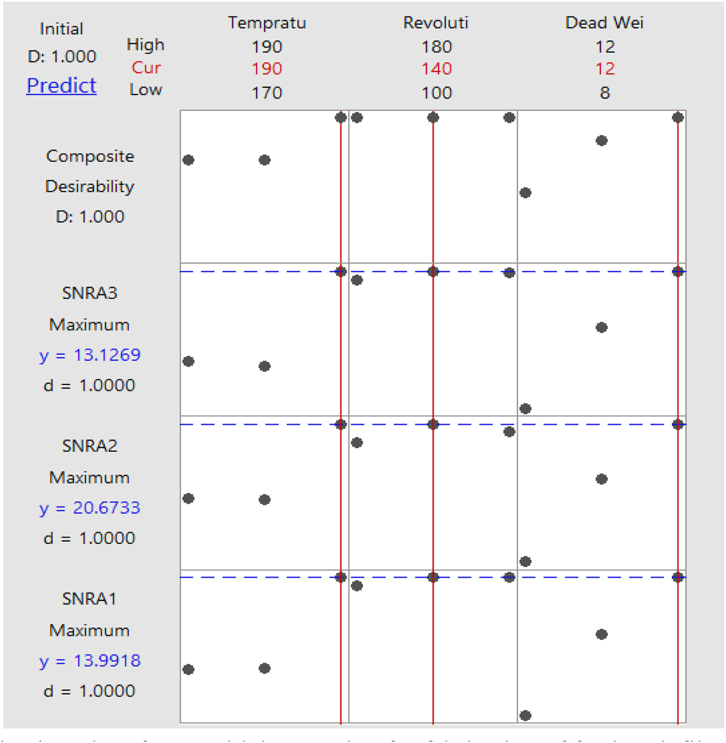
Optimization plot of TSE with best setting for fabrication of feedstock filament.
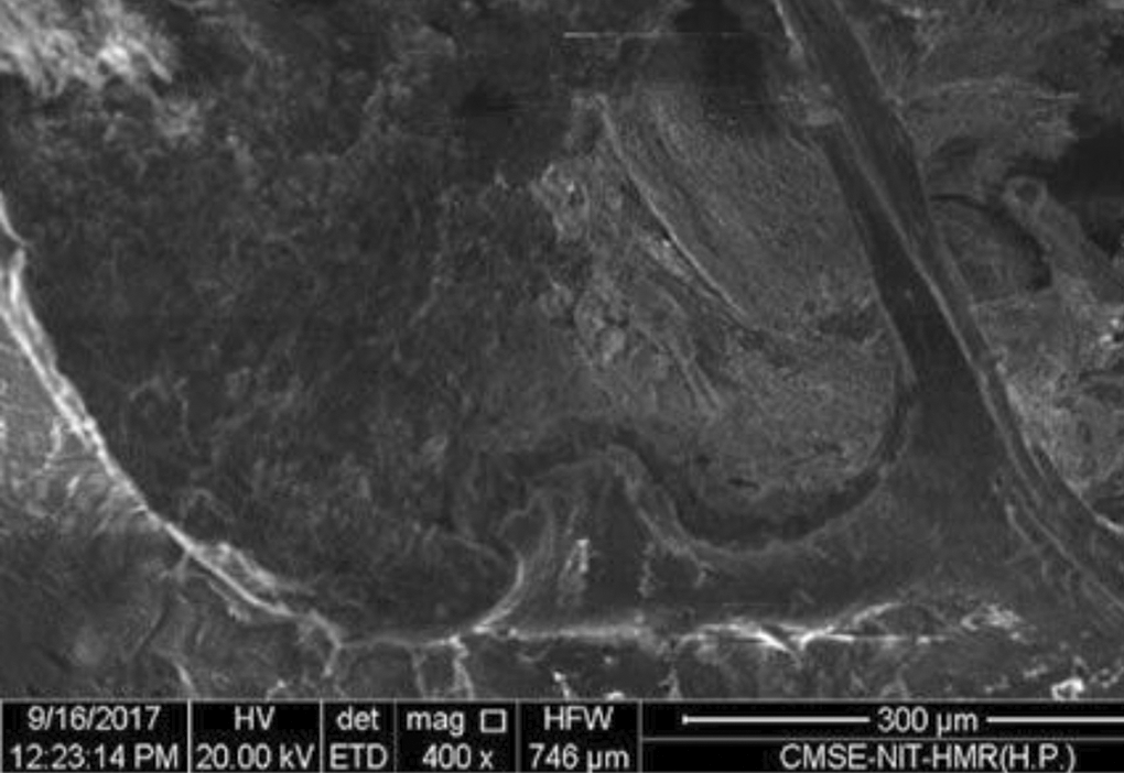
SEM image of feedstock filament prepared (according to settings proposed in Table 9).
Optimization of FDM setting for fabrication of biomedical scaffolds (fabrication of tensile and flexural sample on FDM)
After optimization of TSE for fabrication/preparation of feedstock filaments of material composition of PLA-HAp-CS (91-8-1), feedstock filaments have been prepared/fabricated on barrel temperature 190°C with 140 r/min of screw speed and 12 kg of weight. Fabricated feedstock filaments are ready to print functional prototypes with open-source FDM printer. Figure 6 shows printing of functional prototypes on FDM printer. Figures 7 and 8 show printed tensile and flexural samples according to Table 6.
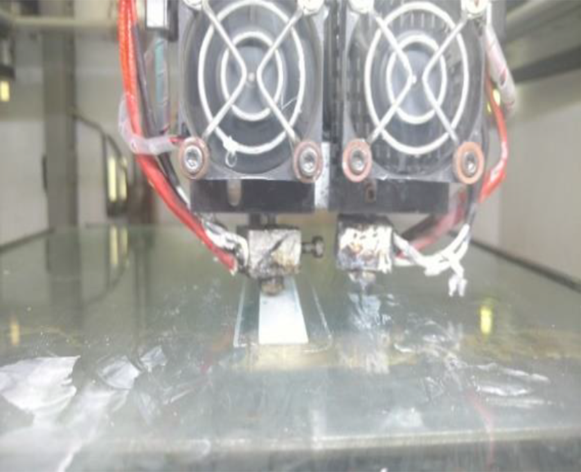
Operational view of open-source FDM during fabrication of flexural sample.
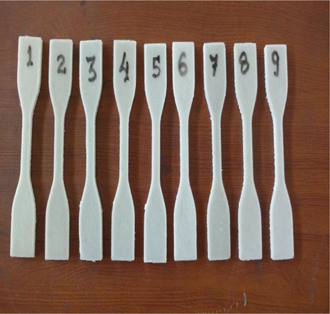
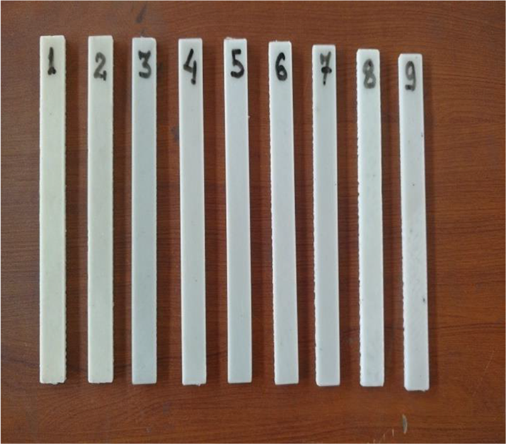
Fabricated part of tensile sample on FDM.
Fabricated part of flexural sample on FDM.
Tensile and flexural samples are prepared according to ASTM standards (tensile sample (ASTM D638 TYPE IV): 125 mm (full length of sample (FL)) × 20 mm (full width of sample (FW)) × 6.5 mm (parallel section width) × 3.2 mm (thickness (H)) and flexural sample (ASTM D790-17): 125 mm (FL) × 12.7 mm (FW) × 3.2 mm (H)).
Multifactor optimization of FDM for tensile sample
Based upon Table 6, Table 10 shows the output parameters of tensile test with SNRA of all tensile samples. Figure 9 shows the 3D view of UTT and explode view of tensile and flexural (three-point bending) testing.
Output data of tensile specimen (ASTM D638 TYPE IV).
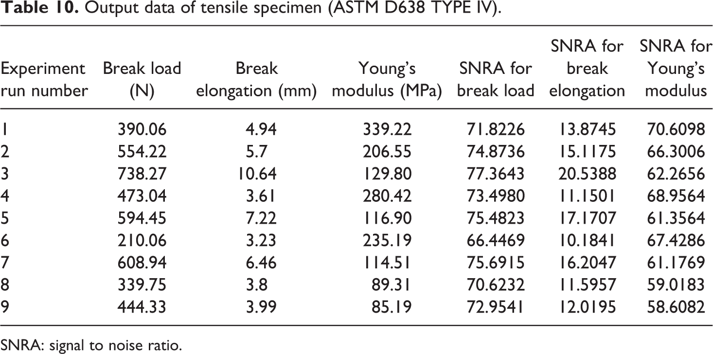
SNRA: signal to noise ratio.
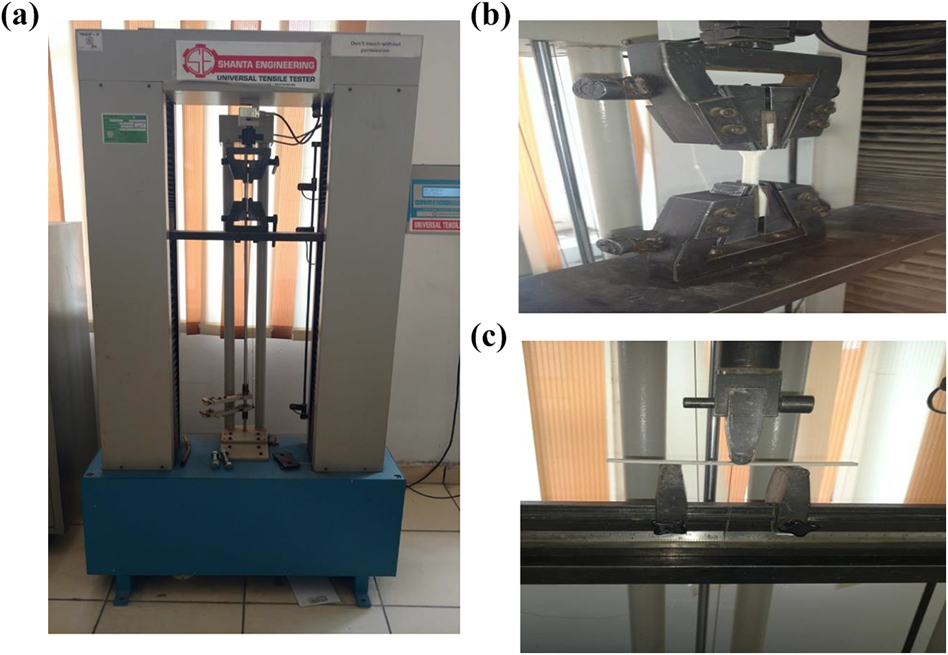
3D view and operational view of tensile and flexural (three-point bending) test on UTT.
Based upon Table 10, multifactor optimization has been done on Minitab 17.00 (software) with output parameters as break load, break elongation and Young’s modulus, and input parameters are layer thickness of tensile sample, deposition angle and infill density.
Table 11 shows the lower and higher value of SNRA of each output parameter and given equally weighted. Further, Table 12 shows the output of multifactor optimization with best settings obtained for tensile samples.
Response optimizer for multifactor optimization for tensile samples.
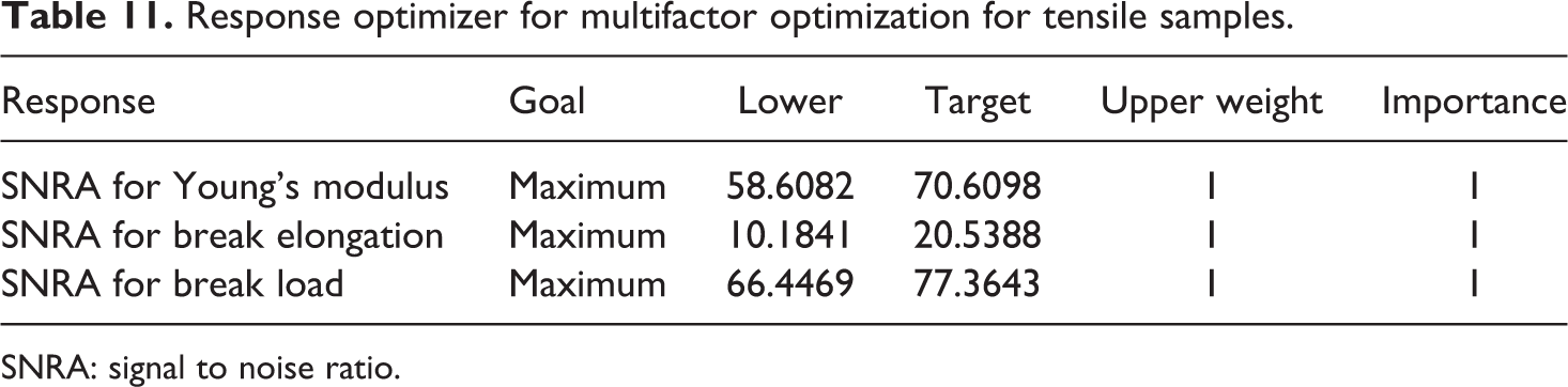
SNRA: signal to noise ratio.
Output of multifactor optimization with best setting obtained with best SNRA for tensile samples.
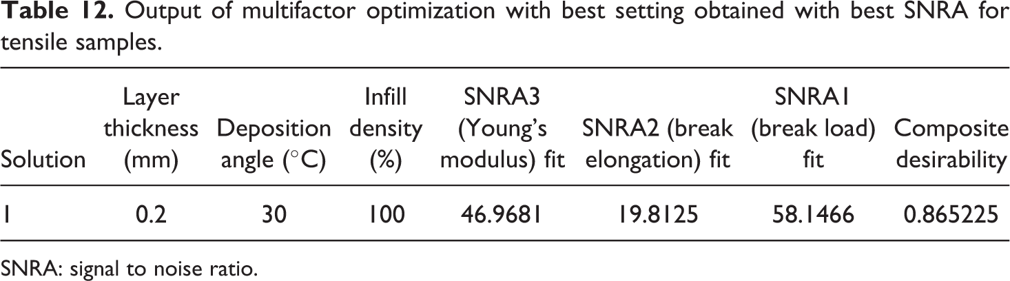
SNRA: signal to noise ratio.
Figure 10 and Table 12 highlight that the best setting for fabrication of tensile sample of composition 91-8-1 (PLA-HAp-CS) is layer thickness of 0.2 mm with deposition angle at 30°C and infill density of100%.
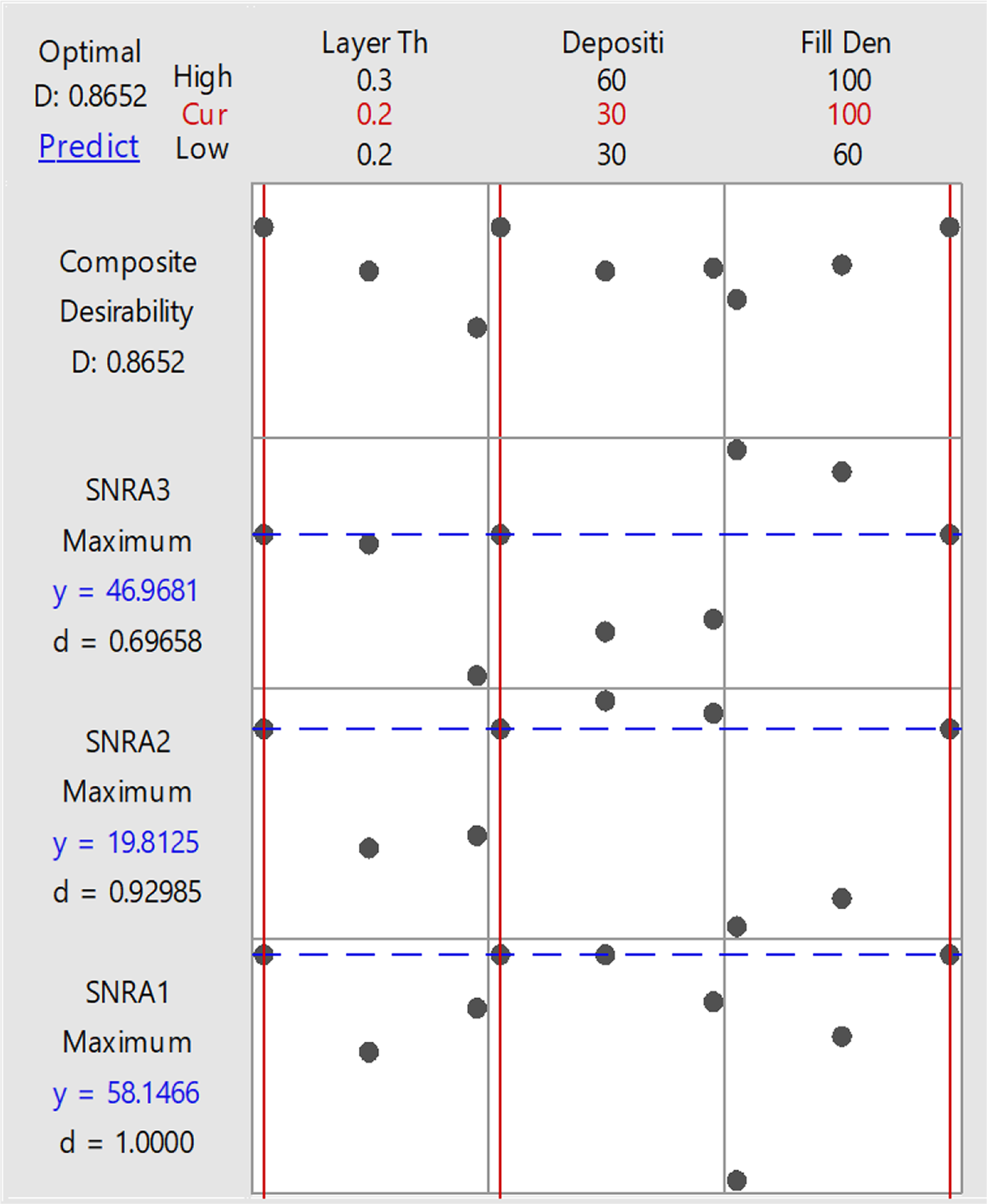
Optimization plot of open-source FDM with best setting for fabrication of tensile sample.
Multifactor optimization of FDM for flexural sample
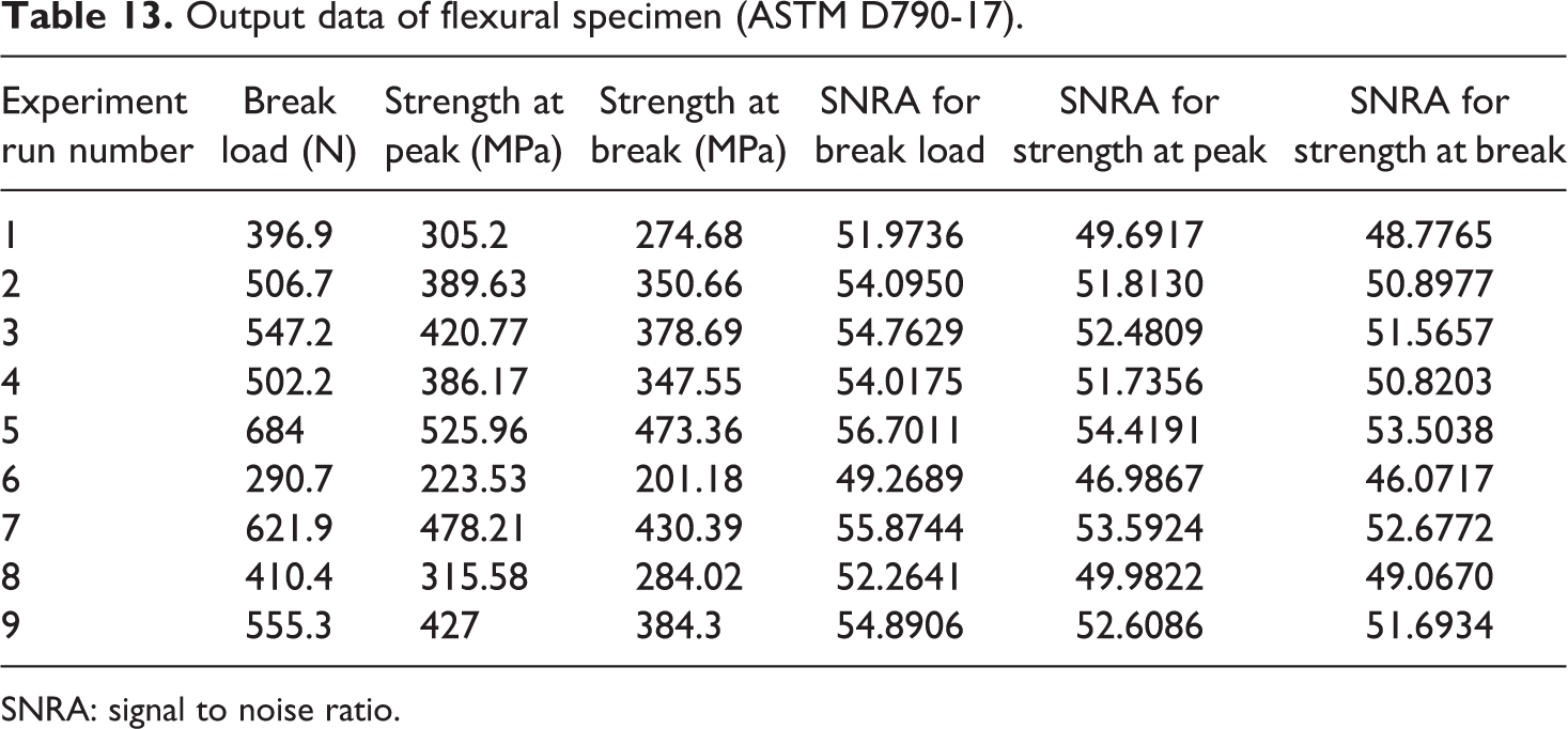
Based upon Table 6, Table 13 shows the output parameters of flexural (three-point bending) test with SNRA of all tensile sample.
Output data of flexural specimen (ASTM D790-17).
SNRA: signal to noise ratio.
Based upon Table 13, multifactor optimization process has done on Minitab 17.00 (software) with output parameters as break load, strength at peak and strength at break, and input parameters are layer thickness of flexural sample, deposition angle and infill density.
Table 14 shows the lower and higher value of SNRA of each output parameter and given equally weighted. Based upon Table 14, Table 15 shows the output of multifactor optimization with obtained best settings for flexural samples.
Response optimizer for multifactor optimization.
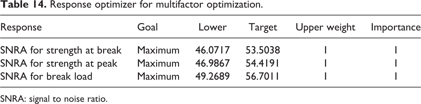
SNRA: signal to noise ratio.
Output of multifactor optimization with best setting obtained with best SNRA for flexural samples.
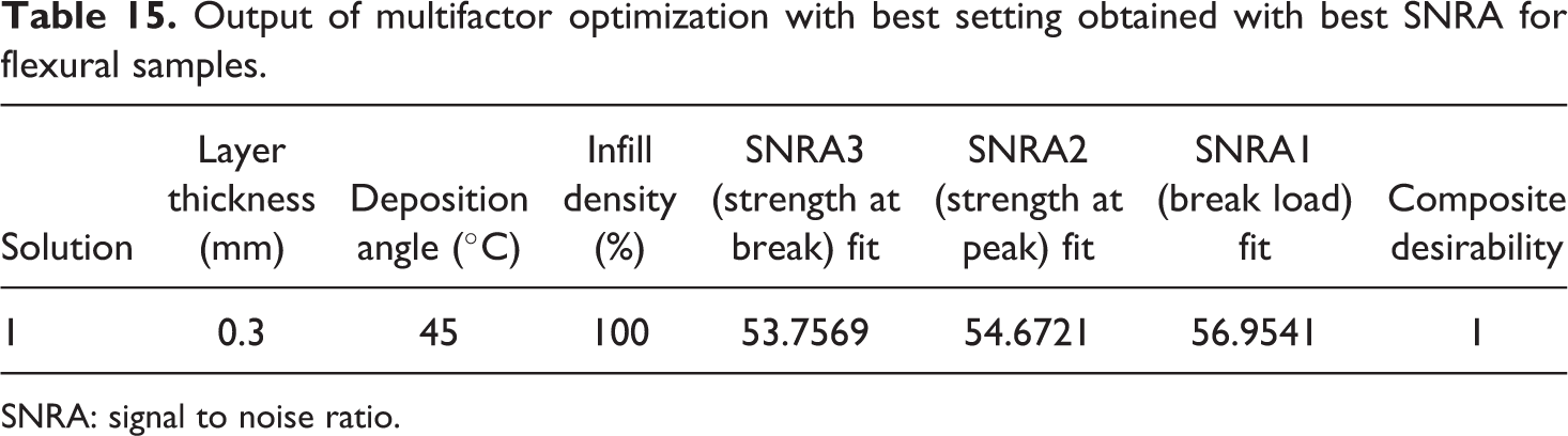
SNRA: signal to noise ratio.
Figure 11 and Table 15 outline that best setting for fabrication of flexural sample of composition 91-8-1 (PLA-HAp-CS) is layer thickness of 0.3 mm with deposition angle at 45°C and infill density of 100%.
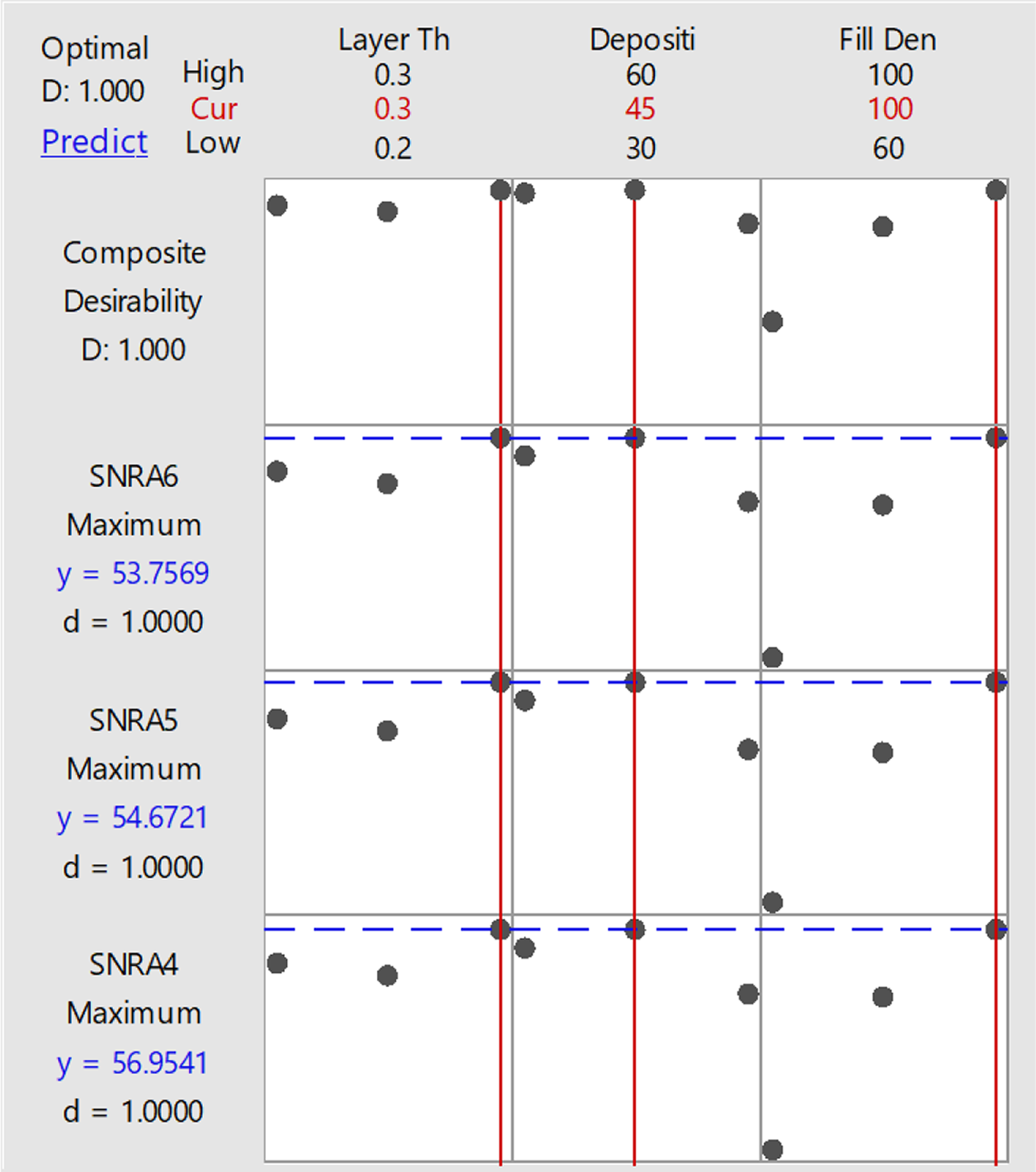
Optimization plot of open-source FDM with best setting for fabrication of flexural sample.
SEM analysis of fractured part of tensile and flexural sample
Tensile and flexural sample are tested on UTT and fractured parts are shown in Figure 12. It has been observed that all samples of tensile and flexural breaks in the midpoint.
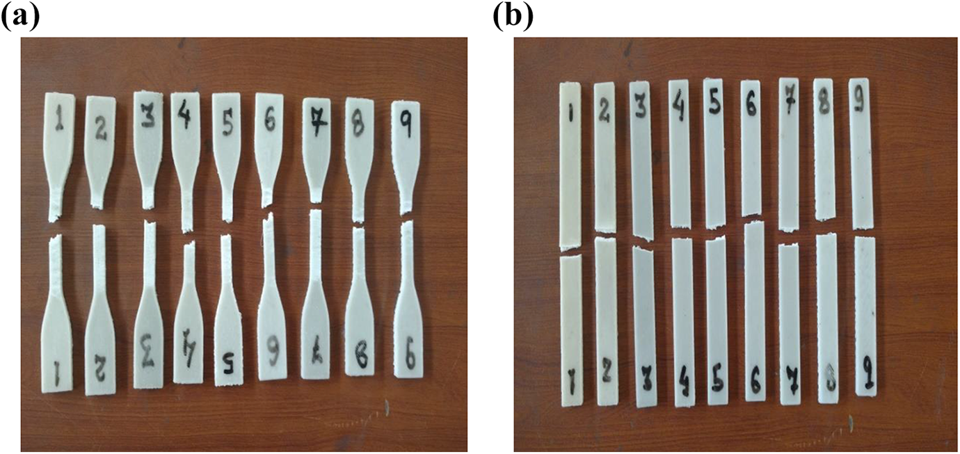
Fractured tensile and flexural samples after testing.
For detailed analysis of fractured part of tensile and flexural sample, SEM analysis has performed. Figures 13 and 14 show the fractured area of tensile and flexural samples at 100× magnification.
SEM view of fractured tensile sample at ×100 magnification power.
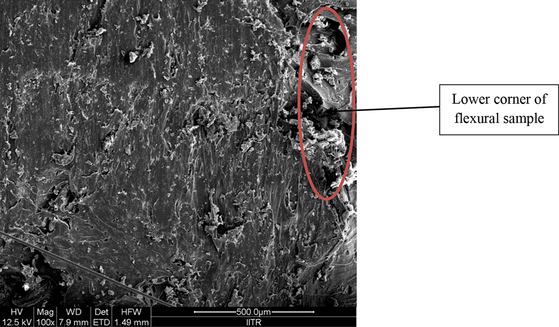
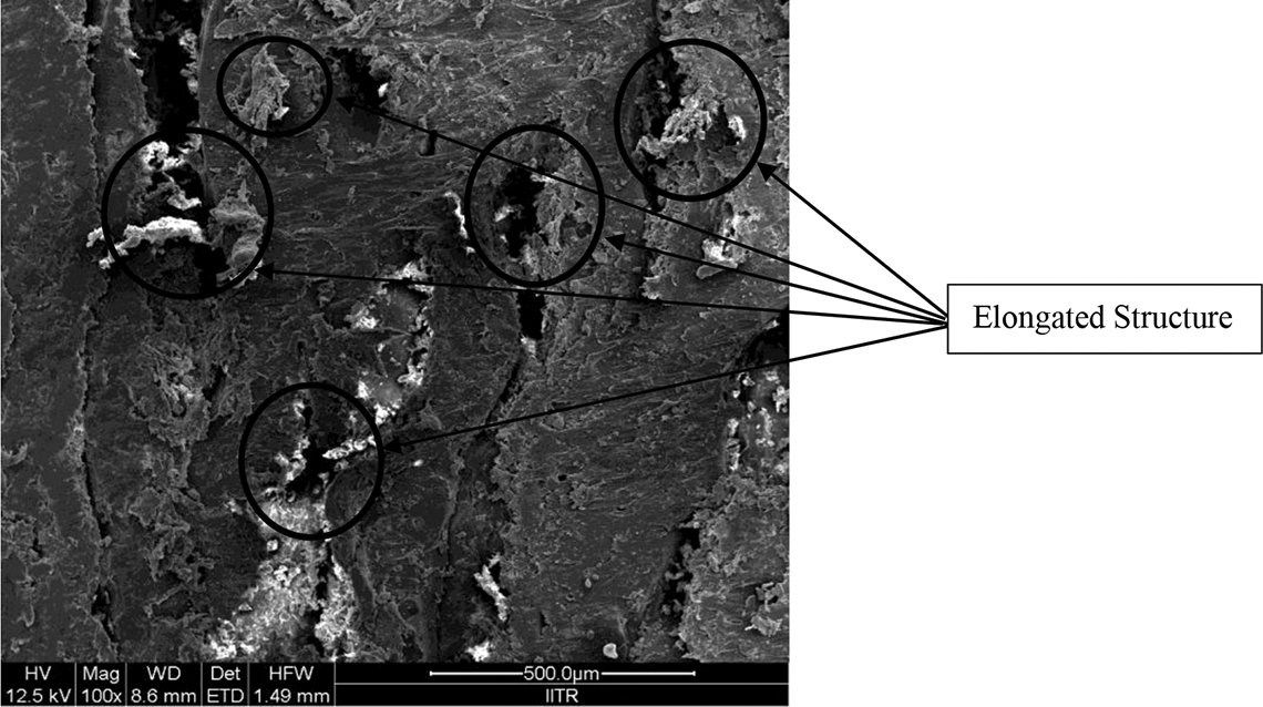
SEM view of fractured flexural sample at ×100 magnification power.
Figure 13 shows open extension fracture. This may be due to the elongated material and grooves, which are ought to be present in tensile (elongation) test. At the time of tensile, test axis perpendicular to the central axis was elongated, hence some elongated part and some groove are present in one face.
Figure 14 shows parallel slip fracture. Here, very less elongation and grooves are present because in flexural test (three-point bending test) only lower part of sample is in tension and sample has cracked with parallel plans.
Figures 13 and 14 also highlight that the PLA-HAp-CS has uniform distribution of reinforcements in whole area of sample and structure similar to open porous structure is obtained (which is good for bone/tissue regrowth/regeneration).
Conclusions
PLA, HAp and CS are suitable materials (polymer and composite) for fabrication/preparation of biocompatible/bioactive/biodegradable scaffolds/implants/ inserts for TE/biomedical engineering applications. HAp is most suited composite material because its characteristic is 99% similar to bone and teeth. CS is bioactive polymers which ignite the tissue in-growth rate and PLA is biocompatible and biodegradable polymer. Following are the conclusions from present study:
For preparation of feedstock, filament of different compositions/proportions of PLA-HAp-CS experimentation was conducted and based upon tensile testing, thermal analysis, MFI, continuous flow ability and dimensional analysis, PLA-HAp-CS as 91%-8%-1% (by weight) proportion has been selected.
Based upon TSE multifactor optimization, the best setting of factors is barrel temperature of 190°C, rotational screw speed of 140 r/min and applied load of 12 kg for fabrication of feedstock filament.
Based upon open-source FDM multifactor optimization according to tensile and flexural sample, the best setting of factors is layer thickness of 0.2 mm, deposition angle of material of 30° (for tensile) or 45° (for flexural) and infill density of sample of 100%.
In SEM analysis of fractured sample of tensile and flexural tests, it has been ascertained that the specimens/functional prototype prepared are structurally suitable for repair/regeneration of bone/fractured bone because the internal structure of the sample is fibrous, open and porous. The porous structure of an implant provides channels for bone in growth. In addition, porosity enhances the biological interlock between implant and bone.
Footnotes
Acknowledgement
The authors are highly thankful to AISTDF Seretariat (file no. IMRC/AISTDF/R&D/P-10/2017, dated 01-02-2018).
Funding
The author(s) disclosed receipt of the following financial support for the research, authorship, and/or publication of this article: This work was supported by AISTDF Seretariat (file no. IMRC/AISTDF/R&D/P-10/2017, dated 01-02-2018).