
Abstract
Hollow silica nanospheres (HSNs) were synthesized via sol–gel method followed by calcination, using positively charged polystyrene (PS) as a hard template, and the tetraethoxysilane as precursor. The inner diameter and shell thickness of the HSNs can be expediently controlled by adjusting the particle size of PS and the amount of ammonia, respectively. The average inner diameters of HSNs increased from 153 nm to 255 nm along with the increasing PS particle size from 150 nm to 300 nm. The shell thickness of HSNs decreased from 20 nm to 12 nm with the increasing amount of ammonia from 1.5 mL to 3.0 mL. The structure of HSNs was verified by Fourier-transform infrared, thermogravimetric, scanning electron microscopy, and transmission electron microscopy characterization. The prepared thermal insulation coating comprised of HSNs shows good temperature retention and thermo-insulating properties, which indicate that the as-prepared HSNs are potentially used as an inorganic filler for thermal insulation coating.
Introduction
In recent years, the building energy consumption is in a period of rapid growth. 1 With stimulating demand for energy efficiency in the building envelope, the thermal insulation coatings have attracted much attention on solving solar radiation heating problems. 2,3 To cut down the undesired heat loss, it can be easily achieved by stuffing the wall thickness using conventional thermal insulation materials such as mineral wool, phenolic resin composite, polyurethane material, 4 expanded polystyrene (PS), 5 or extruded PS; however, increased wall thickness is unfavorable as actual floor space is lost, and these materials are at risk of flammability, or install super-insulated materials such as aerogel blankets or vacuum insulation panels. 6 What’s more, the major defects with those state-of-the-art thermal insulation materials today are their high cost, fragility, risk of puncturing, and aging issues 7 that hinder their practical use in many areas.
Nowadays, the new nanotechnology materials have been widely applied in building envelopes. 3,8 It has been revealed that compared with other thermal insulation materials, hollow nanostructured insulation materials have lower density 9 and larger surface area 9 that can be used as light filler 2 to reduce energy loss in buildings without increasing wall thickness and also bring some new properties, 9,10 such as sound insulation, flame retardant, and heat insulation. 11 Hollow silica nanospheres (HSNs) contain inert air inside the outer thin-walled shell (tens of nanometer), 2,12 which aims to utilize physical principles such as the Knudsen effect 13,14 to reduce thermal conductivity of materials to a minimum. 15 The unique structure and properties of HSNs 15,16 make them a multifunctional material in various applications such as efficient catalysts, optical devices, solar batteries, 17 drug delivery carriers, and thermal insulators. 15,18
There are many chemical and physicochemical ways 19 to synthesize hollow nanospheres, such as heterophase polymerization combined with sol–gel method, 20 layer-by-layer (LBL) 21 self-assembly process, and surface living polymerization processes. 22 Meng Wang et al. 23 used cetyltrimethylammonium bromide as the soft template for the preparation of tailored silica microspheres. However, the hollow microspheres prepared by the soft template method is not homogeneous and requires the preparation of reverse micelles or reverse microemulsions by using organic solvent in large amount, which puts a potential threat to the environment. Besides the low yield of hollow microspheres, the soft template method is not appropriate for large-scale production. Frank Caruso et al. 24 fabricated the hollow inorganic silica and inorganic hybrid spheres through the colloid template electrostatic LBL self-assembly of silica nanoparticle (SiO2)-poly(diallyldimethylammonium chloride) multilayers, followed by the removal of PS core. But the LBL method is not suitable for the preparation of hollow structure with diameters less than 200 nm. Compared with other methods, the mechanical strength of the hollow structure inorganic material prepared by LBL method is not enough. The structure of the polymerized cavity is stable only in solution, and easy to collapse after drying. Lusi Ernawati et al. 2 successfully prepared the hollow silica particles by a sol–gel method using PS as hard template starting from tetramethyl orthosilicate (TMOS) instead of the traditionally used ethyl ester. The shell thickness was controlled from 6.2 nm to 17.4 nm by increasing TMOS concentration and the diameter change from 95 nm to 430 nm through the use of different sizes of PS particles. However, the shell thickness of the hollow silica particles controlled by TMOS concentration was not economical enough compared with adjusting the amount of ammonia.
The hard template method is most widely used in the preparation of hollow nanospheres because of its convenience and facile access to start materials. 19 It is worth pointing out that PS nanospheres have many advantages as templates for the synthesis of hollow nanostructures, such as the ease of synthesis of monodisperse PS nanospheres with controlled diameters. 25 Moreover, PS nanospheres as a sacrificed template can be easily removed by heating or dissolution. 22
In this article, we use HSNs as inorganic filler to improve the thermal insulation performance of the coating. We first use positively charged PS nanospheres prepared by dispersion polymerization as a hard template, which ensures the negatively charged SiO2 can be easily coated on the surface of PS by electrostatic adsorption. 26,27 Then the silica forms a shell on the core particle via the ammonia-catalyzed hydrolysis and condensation of tetraethyl orthosilicate (TEOS) at 30°C. The formation of HSNs was followed by calcination at 550°C. The inner diameter and shell thickness of the HSNs can be expediently controlled by adjusting the particle size of PS and the amount of ammonia, respectively. Despite the broad range of discussions of their structural complexity and fabrication, only a little is well known to date on the thermal insulation performance of HSNs in application. Here, we wish to introduce this material as a filler to study the influences of thermal transport in coatings. Consequently, the thermal insulation coating using the prepared HSNs as inorganic filler shows good temperature retention and thermo-insulating properties. The morphology and structure of the prepared HSNs were examined by Fourier-transform infrared (FTIR), thermogravimetry (TG), scanning electron microscopy (SEM), and transmission electron microscopy (TEM). The thermal insulation performance was tested by a self-made temperature test installation (JG/T 235-2008).
Experimental
Materials
All reagents used were of analytical grade. Styrene (St; Damao Chemical Reagent Co., Ltd., Tianjin, China) was purified via treating with 5% sodium hydroxide (NaOH) aqueous solution. 2,2′-Azobis(2-methylpropionamideine) dihydrochloride (AIBA; Tianjin Kermel Chemical Reagent Co., Ltd., Tianjin, China) was recrystallized from ethanol before use. Polyvinylpyrrolidone (PVP; K29-32, Aladdin Reagent Co., Ltd., Shanghai, China) with an average molecular weight of 58,000 was used as a stabilizer. Ammonium hydroxide solution (28–30 wt%, Guangdong Guanghua Science and Technology Ltd., Guangzhou, China) was used as catalyst. Anhydrous ethanol (>99.7%, Guangdong Guanghua Science and Technology Ltd., Guangzhou, China) was used as solvent. The re-dispersible acrylic powder was self-made according to our previous references. 28 –31 Deionized water was employed in all experiments.
Synthesis of positively charged PS spheres with varying size
The cationic PS particles were synthesized via dispersion polymerization. First, PVP was dissolved in 180 mL distilled water under ultrasonic dispersion, followed by the addition of St, and different PVP/St ratios including 2 g PVP/20 g St, 3.67 g PVP/18.35 g St, 5.07 g PVP/16.9 g St were designed in this procedure. After that, the dispersion was transferred to a 500 mL four-necked round-bottom flask equipped with a Teflon mechanical stirring blade. The obtained dispersion was heated to 70°C by stirring at 250 r/min for 15 min. Then, 20.4 g of AIBA solution (0.4 g of AIBA and 20 g of deionized water) was added into the above dispersion. The polymerization reaction was maintained at 70°C for 8 h. After the reaction, the obtained PS nanosphere suspension was cooled down to the room temperature.
Coating the PS templates with silica
One hundred and ninety grams of ethanol and 12 g of prepared PS templates were magnetically stirred for 15 min before 1.5, 3.0, and 6.0 mL of ammonia were added, respectively. Then, 20 mL of TEOS solution (10 mL of TEOS in 10 mL of ethanol) was added, used for coating procedure. The reaction was vigorously stirred for 24 h, and the temperature maintained at 35°C.
Synthesis of HSNs
The SiO2-coated PS was obtained by reduced pressure distillation at 70°C to evaporate the solvent. Finally, organics were removed by calcination at 550°C for 8 h and HSNs were obtained.
Preparation of thermal insulation coating
The self-made re-dispersible acrylic powder was used as the binder material. The re-dispersible acrylic powder is prepared as follows: (1) The synthesis of polyacrylate latex was conducted using a semi-batch seeded emulsion polymerization. 28 The latex particles were designed with a special soft core and hard shell configuration, which had a unique T g of −20°C and 48°C, respectively. The detailed formulation and process could be found in the literature. 29,30 (2) A spray drying apparatus was used to dry the obtained latex for preparing redispersible polymer powder (RPP) . The polyacrylate latex was firstly tuned to pH 9.0 with 2.5 wt% NaOH solution, and then silica sol, which was used as drying agent to prevent the polyacrylate particles from agglomerating and improve the re-dispersibility of RPP, was added to the latex. The mixture was fed into the centrifugal spray drying tower, with the inlet temperature being 140 ± 5°C, the rotation speed of atomizing disc being 24,000 r/min, the feed rate being 80 g/min, and the outlet temperature being 75 ± 3°C. The product was separated by a cyclone separator and collected in the storage tank. This process had been discussed in details in our previous work. 31
According to the formula in Table 1, the raw materials were mixed evenly to obtain the thermal insulation coating. The thermal insulation coating was conducted on a glass plate (80 mm × 150 mm) with a brush and then dried at room temperature for 7 days for testing. The dried film thickness of coating is of 0.5 mm according to JG/T 235-2008.
The formula for the thermal insulation coating.
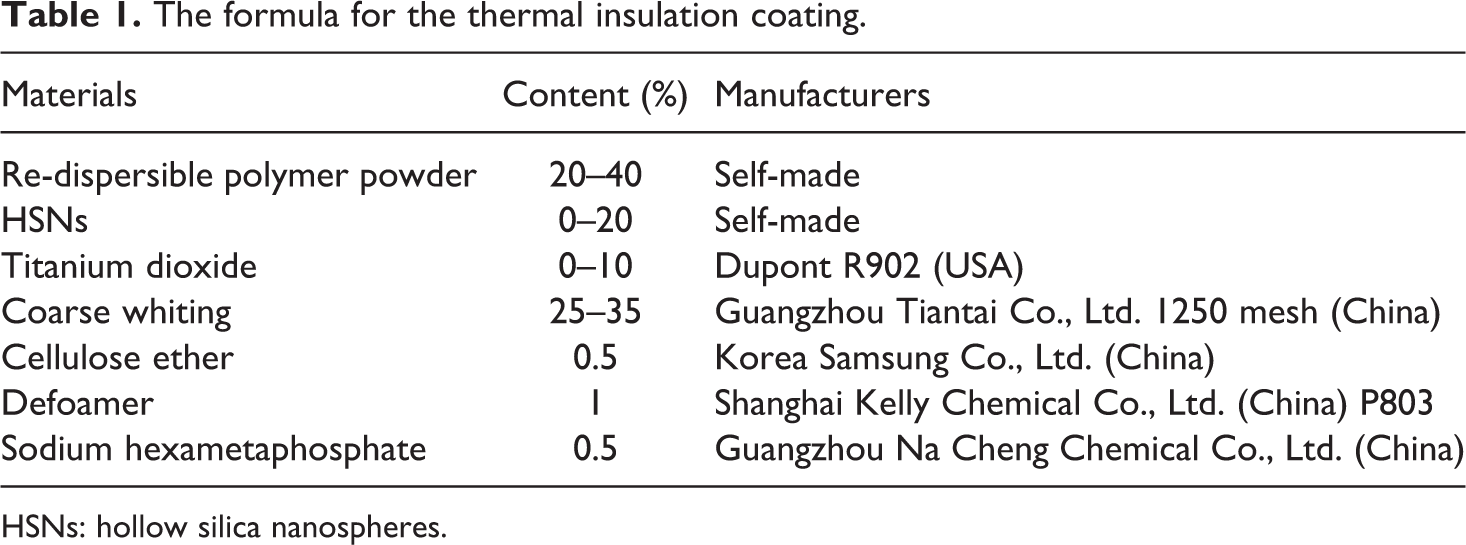
HSNs: hollow silica nanospheres.
Characterization
FTIR analysis
FTIR analysis of SiO2-coated PS templates and HSNs was investigated by a Spectnlm2000 spectrometer (PerkinElmer Co., Fremont, USA). The scan wavenumber was in the range of 500–4000 cm−1. The samples were prepared by usual KBr pellet method.
Scanning electron microscopy
The particle morphology was characterized by field-emission scanning microscopy (ZEISS ULTRA 55, Jena, Germany). Samples were dispersed in ethanol, dried on an electroconductive paste, and sputter-coated with platinum (Pt) prior to examination.
Transmission electron microscopy
Transmission electron microscope (HITACHI H-7650, Hitachi, Japan) was utilized to characterize the particle morphology operating at 80 kV. The samples of PS and HSNs for TEM observation were dispersed in ethanol and ultrasonicated for 30 min and then dried onto 400 mesh carbon-coated copper grids before examination.
TG analysis
TG analysis (TGA) was conducted with a Netzsch TG 209 thermo-analyzer instrument (Netzsch TG 209, Freisaat Bayem, Germany). All the samples were heated in a temperature range of 30–800°C under nitrogen atmosphere at a heating rate of 10 K/min.
Dynamic light scattering measurements
Dynamic light scattering (DLS; Malvern Mastersizer 2000, Malvern, UK) was used to measure the particle size and size distribution of PS spheres at 25°C. The PS sphere sample for DLS characterization was diluted with deionized water and treated for 15 min under ultrasonication.
Water resistance
The thermal insulation coating was conducted on a glass plate (80 mm × 150 mm) with a brush and then dried at room temperature for 7 days to remove the contained water. The dry film of the thermal insulation coatings was immersed into the distilled water. The foaming time of the film surface will be recorded.
Scratching resistance
The scratching resistance was tested by the PG-V architectural coating scrubbing tester (Guangzhou, China). During the scrubbing process, the 0.5 wt% of the detergent water should be added continuously to the plate.
Thermal insulation properties
The thermal insulation properties were measured by a self-made installation (Figure 1) with two thermocouples and two 135 W infrared lamps. The thermal insulation coating was conducted on a glass plate (80 mm × 150 mm) with a brush and then dried at room temperature for 7 days for testing. The actual temperature was detected via thermocouples.
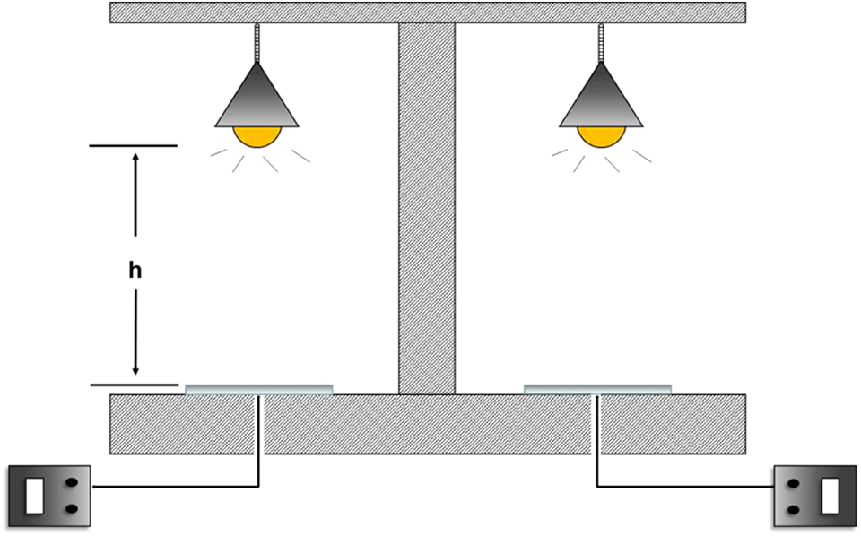
Schematic view of the simple temperature test installation.
Results and discussion
Formation mechanism of HSNs
The formation of the HSNs via hard template method consists of three steps.
First, AIBA was considered as a cationic radical initiator. The PS template was synthesized via dispersion polymerization with a positive zeta charge. The second step was the hydrolysis reaction of TEOS to synthesize the silica-coated PS. The opposite charge between the positively charged PS and negatively charged silica particles makes the electrostatic attraction phenomenon. 27 The silica particles are attached on the surface of PS sphere to form the core–shell structure. 13 The final step was the removal of the PS template through calcination. The organic PS template was decomposed under 550°C for 8 h. But the silica particles remain to obtain the HSNs. Figure 2 shows the whole formation process of HSNs.
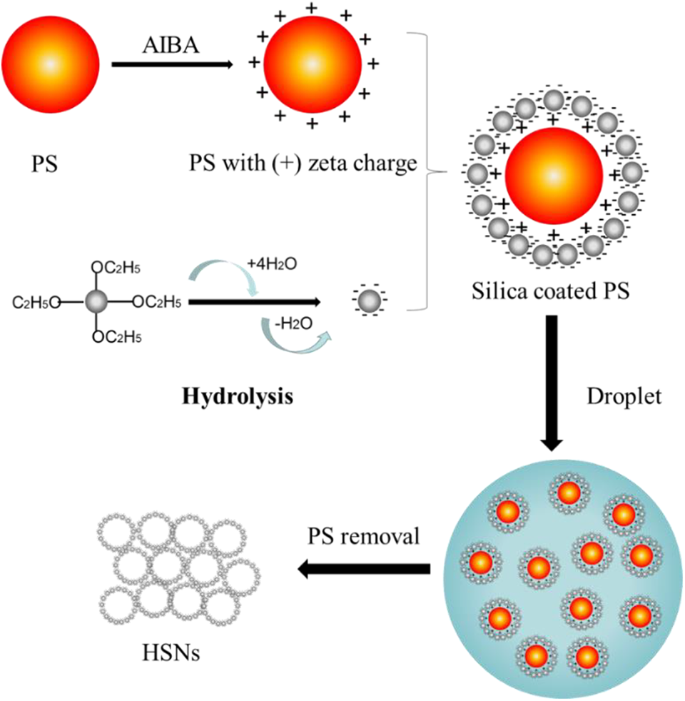
Schematic drawing of the formation of the HSNs with (+) zeta charged PS via hard template method.
The thermal conductivity of HSNs can be given as 15,16

where λt stands for the total thermal conductivity of HSNs, λs stands for the solid conductivity, λg is the gaseous conductivity in HSNs, and λr is the radiative conductivity.
For HSNs, because of a small quantity of solid and abundant of bounded gas, the bulk densities of powder hollow spheres are very low, which result in the very small solid conductivities λs. The calculated results indicate that the solid part is of negligible contribution to the total conduction. The radiation is usually neglected at cryogenic condition, while at high temperature the radiation contributes mainly to the total thermal conductivity. As for the silica hollow spheres, the λr values at T = 303 K are much less than the λg values. Therefore, the gaseous conductivity contributes decisively to the total thermal conductivity. Thus,
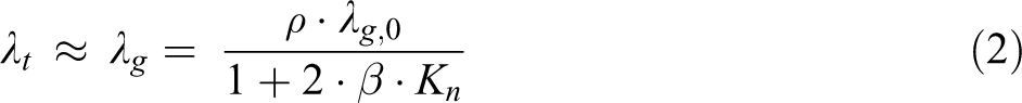
where ρ is the porosity, λg,0 = 0.026 W/(mK) is the thermal conductivity of bulk air at ambient condition, β is a constant depending on the type of gas (for air, β ≈ 2), and Kn = l/d is the Knudsen number with l being the gas molecule mean free path (for air, l ≈ 68 nm at ambient condition) and d being the mean internal diameter of HSNs.
The internal diameter is the interdependent parameters affecting the thermal conductivity of the hollow silica spheres. The alterations of it will lead to obvious changes in the thermal conductivity, which is proved by experimental and calculated values. The powder hollow silica sphere materials are high efficient insulators, which are promising in aerospace and civil buildings fields.
Morphology and structural features of HSNs
Figure 3 shows SEM and TEM images of PS, SiO2-coated PS, and HSNs. As we can see from Figure 3(a), the prepared PS template shows a smooth surface and monodisperse distribution. From Figure 3(b), the surface of PS template becomes rough with some of the scattered silica particles around but maintain a spherical morphology and narrow size distribution after coated with silica. Compared Figure 3(c) with Figure 3(b), after calcination, the spherical structure did not collapse. It is clear from the TEM image that Figure 3(f) has formed a complete hollow structure. Above all, it’s worth to note that the PS inside the shell was removed after calcination, while the original spherical structure didn’t change.
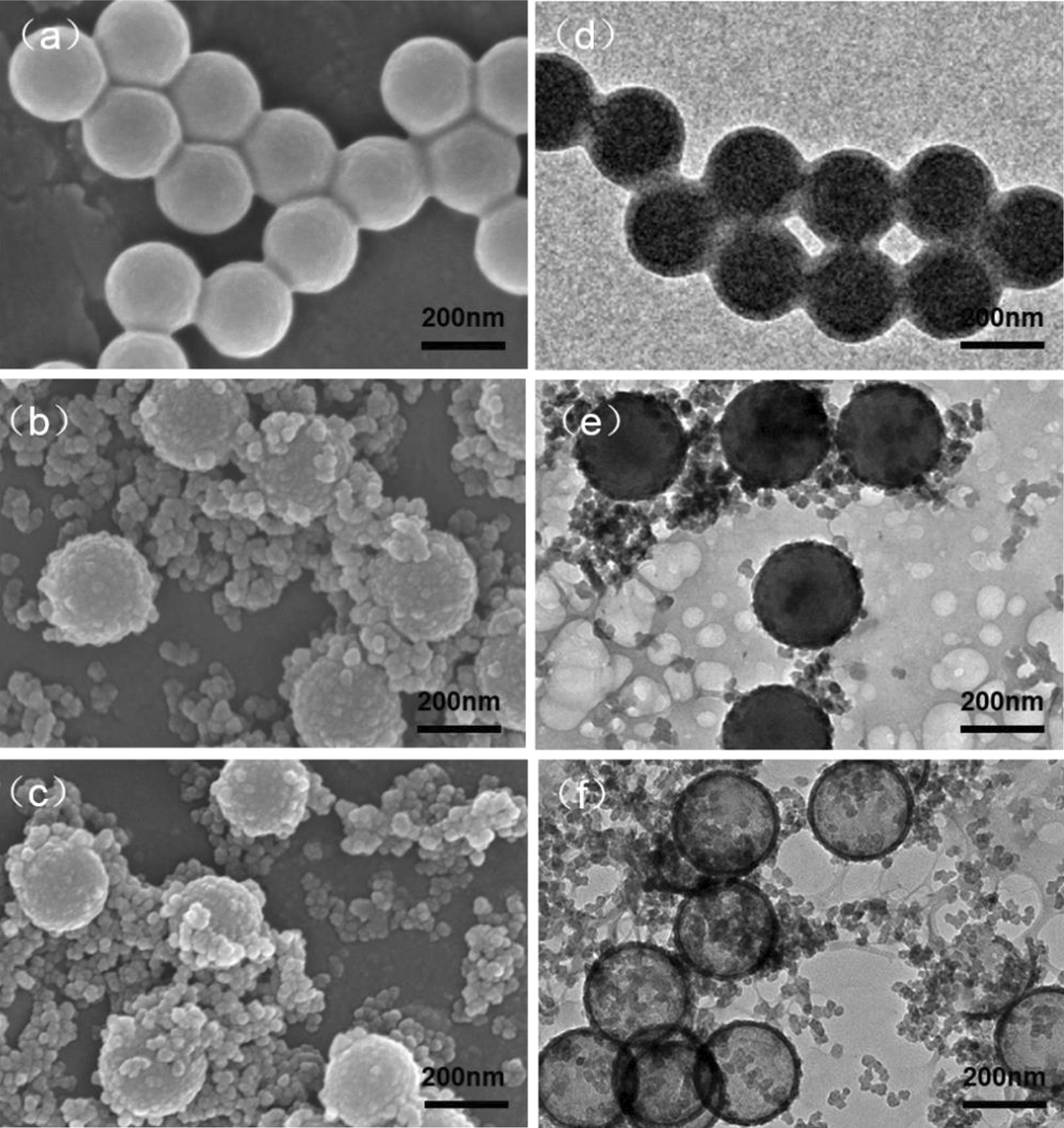
SEM and TEM images of PS (a, d), SiO2-coated PS (b, e), and HSNs (c, f).
FTIR, TGA, DLS, and TEM analysis of HSNs
FTIR spectra of SiO2-coated PS templates and HSNs are displayed in Figure 4(a) and (b), respectively. It can be observed in Figure 4(a) that the absorption peaks appeared at 1087 and 964 cm−1 assigned to Si–O–Si stretching vibration for SiO2, which indicates the existence of silica particles. The two absorption bands at 1652 and 1492 cm−1 represent the C=C vibration absorption peak of the benzene ring of PS. The absorption bands at 3028 and 2927 cm−1 are the C–H stretching vibration peaks of benzene ring of PS. Stretching vibration band at 3411 cm−1 stands for hydroxyl peak on the surface of SiO2.
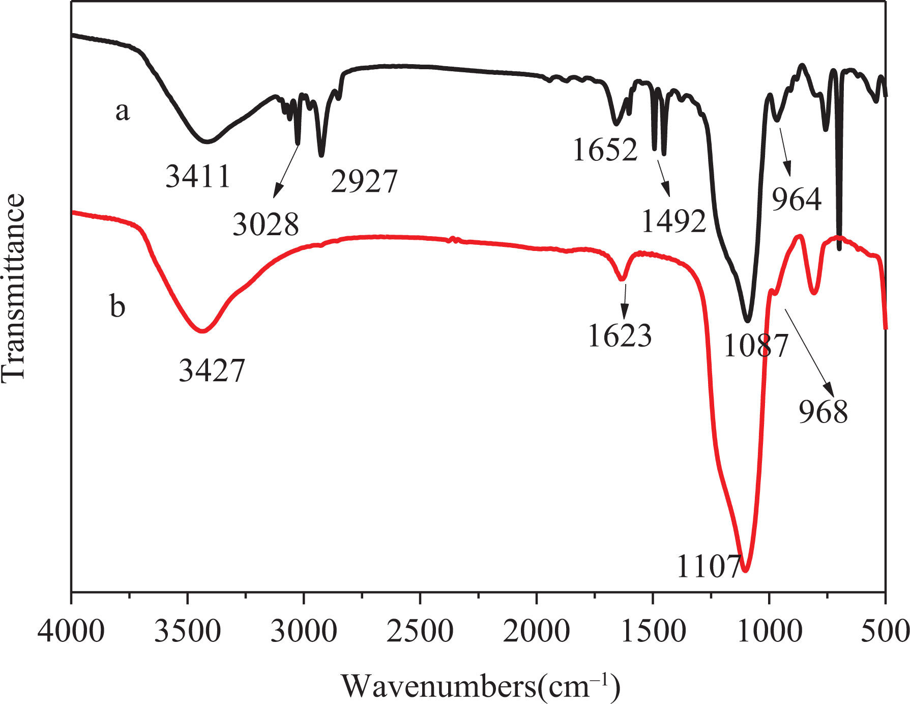
FTIR spectra of SiO2-coated PS templates (a) and HSNs (b).
It can be seen from Figure 4(b) that, after calcination, the hydroxyl still exists on the surface of SiO2. The antisymmetric stretching vibration peaks and the bending vibration peaks of Si–O–Si at 1087 and 964 cm−1 remain. However, the characteristic absorption peaks of benzene ring disappeared completely, indicating that PS template was completely removed by calcination.
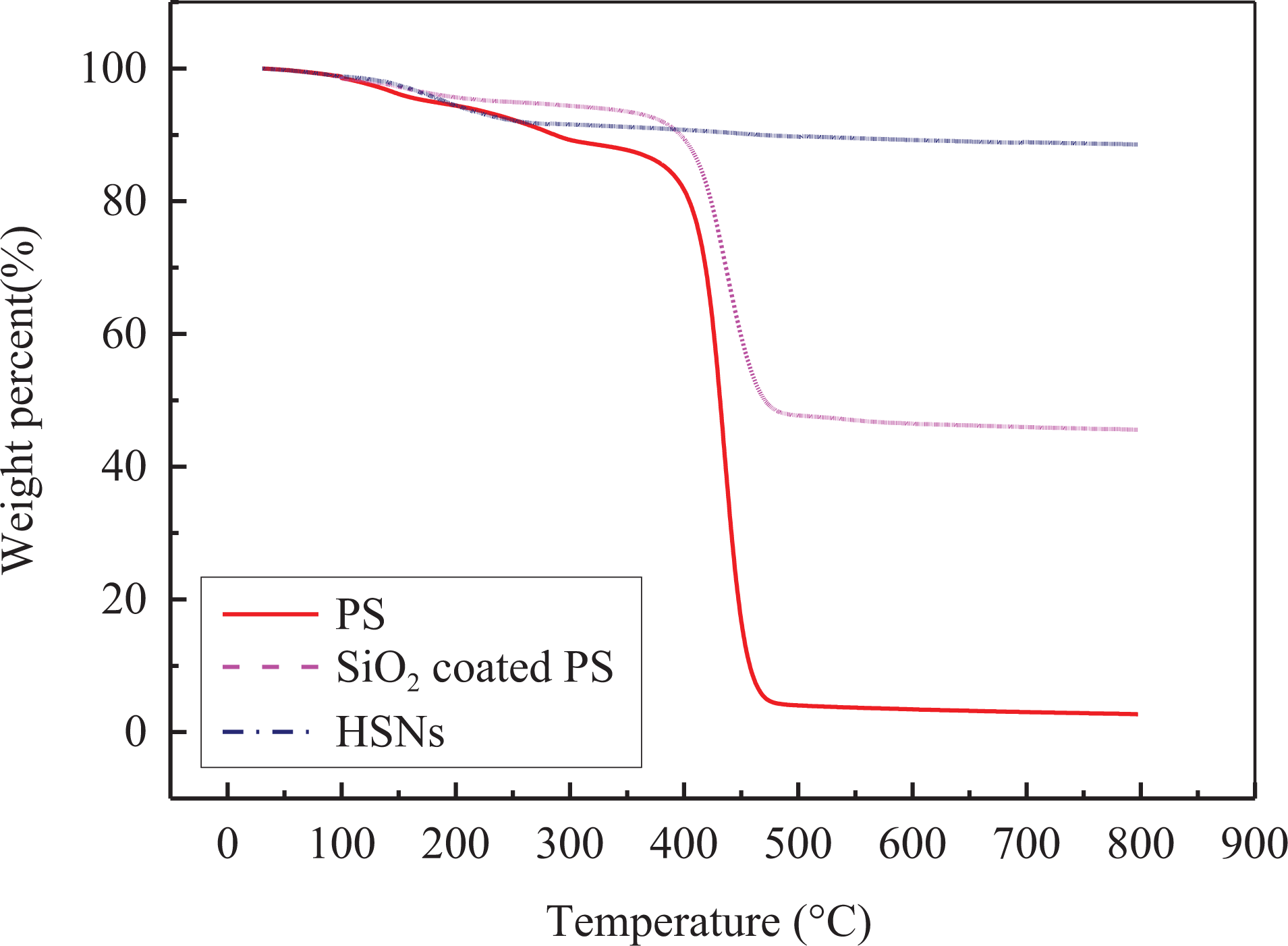
Figure 5 presents the TGA curves of the original PS (Figure 3(a) and (d)), SiO2-coated PS templates (Figure 3(b) and (e)), and HSNs (Figure 3(c) and (f)).
TGA curves for PS, SiO2-coated PS, and HSNs.
As seen in Figure 5, the weight loss stages under 300°C are corresponding to evaporation of physically absorbed water. For PS template and SiO2-coated PS, the broad weight loss stages between 400°C and 450°C are corresponding to the decomposition of PS template. For HSNs, the main weight loss stages occur in the regions below 300°C, which also indicates that all the PS are removed.
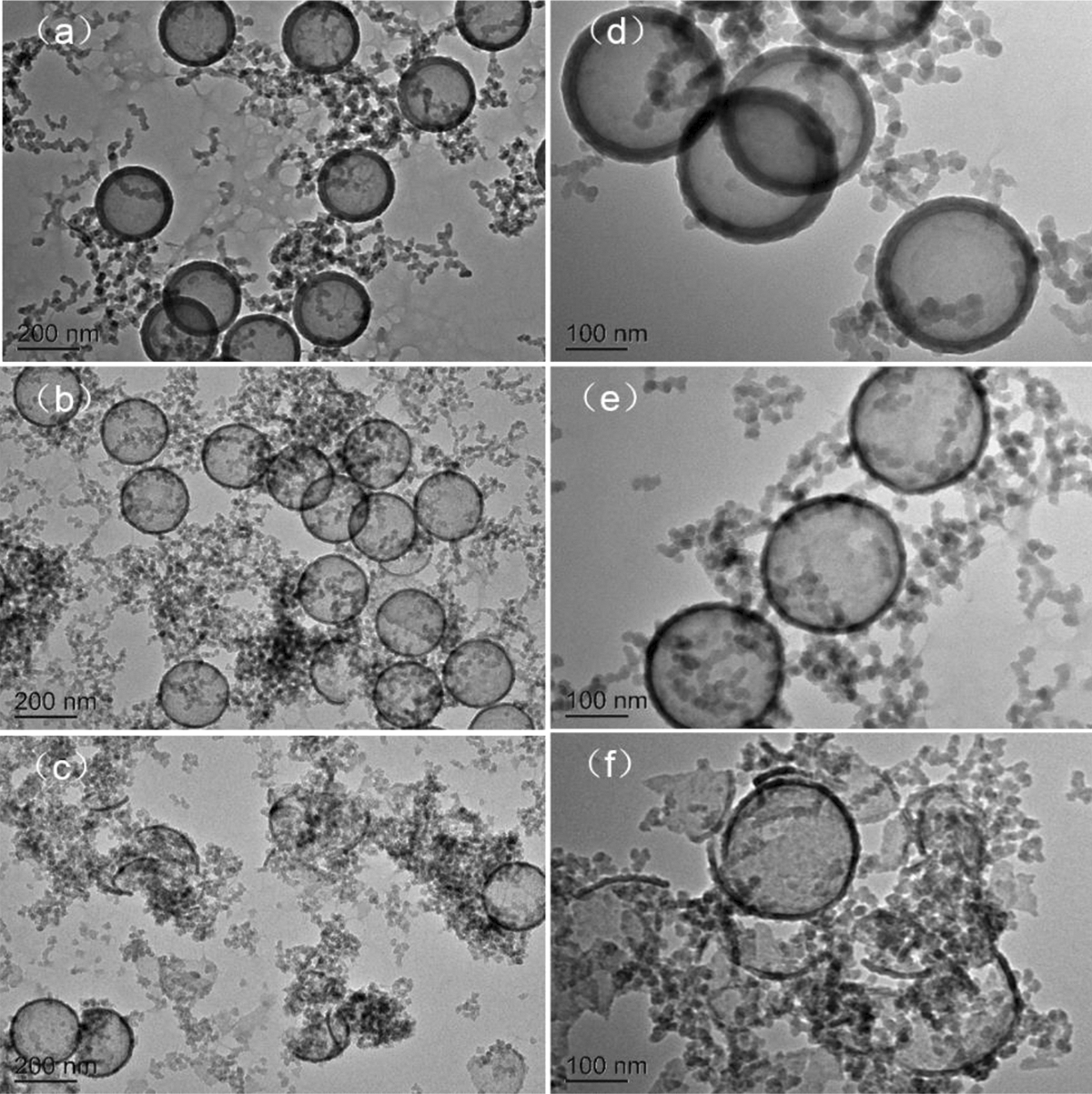
It is reported that there are several parameters have effects on both size and dispersibility of the PS nanospheres. The size of the PS nanospheres can be controlled by changing the ratio of PVP/St. As shown in Figure 6, PS nanospheres with diameters of about 300 nm can be obtained when the PVP/St weight ratio is about 0.1, whereas increasing the PVP/St ratio to about 0.2 and 0.4 results in PS nanospheres with smaller diameters of about 230 and 150 nm, respectively. From Figure 6(a) to (c), the average inner diameters of HSNs increased from 153 nm to 255 nm along with an increase in PS particle sizes from 150 nm to 300 nm. Therefore, we can alter the size of HSNs by changing the size of PS particles, as showed in Figure 6(a) to (c) which correspond to the size measured using DLS.
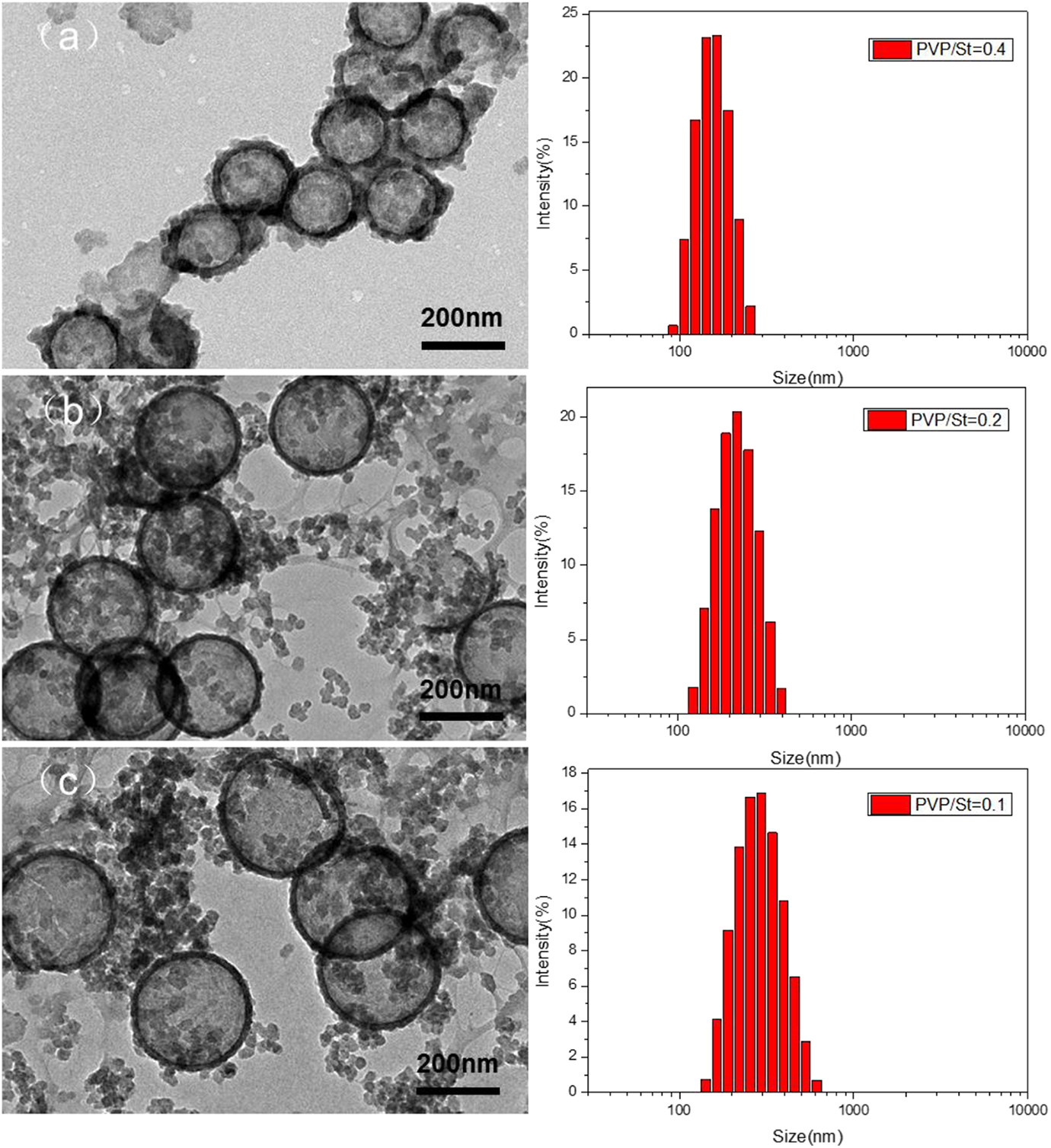
TEM images of HSNs prepared with different PS diameter of 150 (a), 230 (b), and 300 nm (c). The PVP/St ratio was kept at 0.4, 0.2, and 0.1, respectively.
Figure 7 shows the TEM images of HSNs prepared in the presence of 1.5, 3.0, and 6.0 mL of ammonia. As showed in Figure 7(a) and (b), when the amount of ammonia was 1.5 mL, the core–shell HSNs were obtained with 20 nm in shell thickness. The TEM photos in Figure 7(c) and (d) showed that the shell thickness of HSNs decreased from 20 nm to 12 nm as prepared with 3.0 mL of ammonia. That is, ammonia acted as an accelerator in the hydrolysis of TEOS. The increase in the amount of ammonia promoted faster hydrolysis and condensation rate, which probably resulted in less SiO2 particles to form a silica shell. When the amount of ammonia was brought to 6 mL, barely no HSNs but SiO2 particles were obtained. That happens because the PS core had been dissolved under this ammonia concentration before the hydrolyzed TEOS coated on the surface of PS spheres. It does mean that the shell thickness of HSNs can be easily controlled within a certain range by adjusting the content of ammonia.
TEM images of HSNs were prepared under various NH3·H2O content: (a, d) 1.5, (c, e) 3, and (d, f) 6 mL.
Application in thermal insulation coating
Table 2 shows the properties of the thermal insulation coatings with different contents of HSNs. As we can see from the results, the appearance, surface drying time, water resistance, and scrubbing resistance of the coatings did not show any significant change, which reveals that it will not bring a negative effect on the performance of the coating even with the addition of HSNs.
The properties of thermal insulation coatings with different HSN contents.
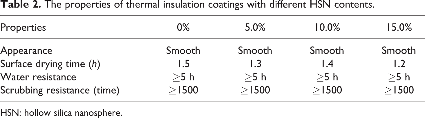
HSN: hollow silica nanosphere.
The thermal insulation properties were characterized by self-made simple temperature test installation as showed in Figure 1.
Figure 8 indicates the temperature variation of the thermal insulating coatings with different contents of HSNs with infrared irradiation time. In the figure, 0%, 5.0%, 10.0%, and 15.0% represents the mass percentage of HSNs in thermal insulation coatings, respectively.
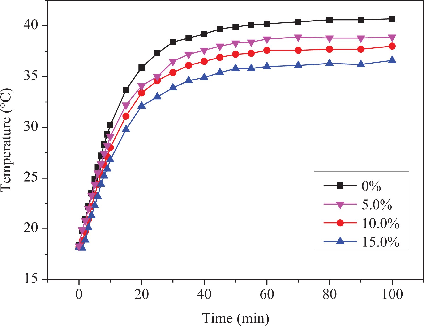
Temperature variation curves of thermal insulation coatings with different HSN contents as a function of the infrared irradiation time.
As it can be clear from Figure 8, the temperature raised inside the test space with the extension of infrared irradiation time, and eventually stabilized. Due to the infrared light irradiation, the heat gets through the glass into the temperature measurement space, therefore the temperature within the space gradually increased. However, a part of heat spread to the air during this process, leading the surface temperature of the two glass rising to a maximum value and then stabilizing. It can be observed in Figure 8 that all the temperature of the samples tends to be stable after 50 min under the infrared lamp. When 5.0% HSNs were introduced, the final equilibrium temperature was 2.0°C lower than that of thermal insulation coating without HSNs. However, with increasing content of the HSNs, the maximum temperature of the final equilibrium in the test room gradually decreased, indicating that the thermal insulation performance of the coating was improved with the increasing content of the HSNs. The reason is that with the increasing content of HSNs, the air content in the coating gradually increased, resulting in the thermal conductivity of the coating reduced.
Previously, Liao et al. 15 reported the internal diameter is the key factor influencing gaseous conductivity while the solid part is of negligible contribution to the total conduction.
Figure 9 shows the temperature variation curves of thermal insulation coatings with different inner diameters at 15.0% HSNs content as a function of the infrared irradiation time. It can be seen from Figure 9 that when the inner diameters of the HSNs are of 150, 230, and 300 nm, the final equilibrium temperatures of the thermal insulation coatings are of 31.5°C, 32.8°C, and 36.4°C, respectively, which indicates that with the decrease of the inner diameter of HSNs, the thermal insulation performance of the coating becomes better. The experimental results are in a good agreement with the theoretical analysis method, as showed in Figure 9. It probably due to a decrease in thermal conductivity when the inner diameter of the HSNs decreases from equation (2). 15 Convective heat transport is suppressed in the submicrometer holes, which are also an effective way to reduce the gaseous conductivity.
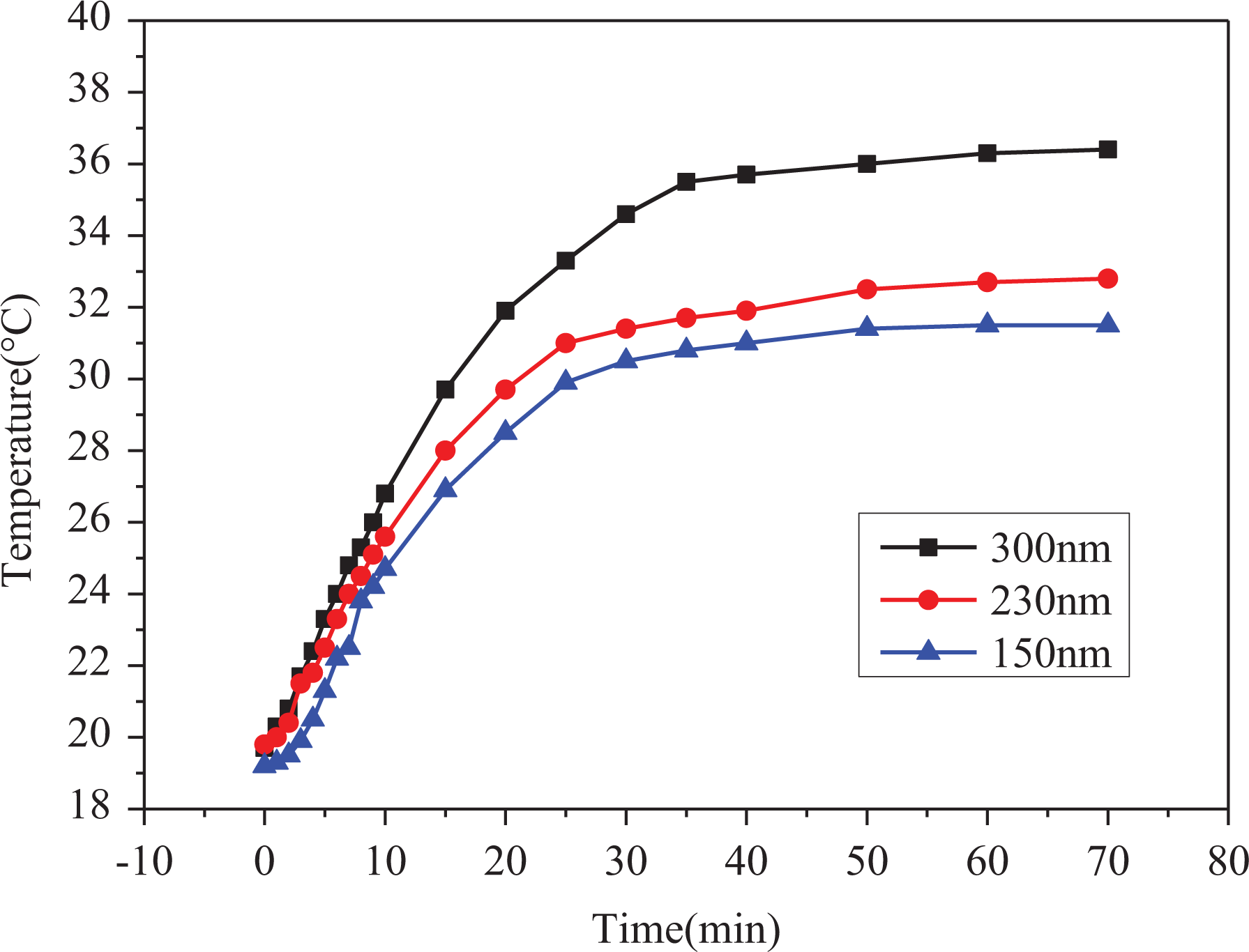
Temperature variation curves of thermal insulation coatings with different inner diameters of 150, 230, and 300 nm at 15.0% HSNs content as a function of the infrared irradiation time.
Conclusions
In summary, a facile approach to prepare hollow silica microspheres with controllable inner diameter and shell thickness based on a dispersion polymerization and sol–gel process was given. The monodisperse positively charged PS particles as hard template are first prepared by dispersion polymerization using AIBA as a cationic radical initiator, and then the silica shells are coated onto the PS particles by the ammonia-accelerated hydrolysis and condensation of TEOS. The prepared HSNs had a great effect on the thermal insulation performance of the coating. When 15.0% HSNs were introduced, the final equilibrium temperature is 5.0°C lower than that of thermal insulation coating without HSNs. With the decrease of the inner diameter of HSNs, the better thermal insulation performance of the coating obtained, which indicates that the HSNs is promising in the requiring thermal insulation coating.
Footnotes
Acknowledgements
The authors gratefully acknowledge the financial support from the Science and Technology Planning Project of Guangdong Province, China, and the Science and Technology Planning Project of Guangzhou Science Technology & Innovation Commission.
Funding
The author(s) disclosed receipt of the following financial support for the research, authorship, and/or publication of this article: This work was financially supported by the Science and Technology Planning Project of Guangdong Province, China (2015A010105008) and the Science and Technology Planning Project of Guangzhou Science Technology & Innovation Commission (201607010049).