
Abstract
The abrasive wear performance of glass–polyamide fibers/epoxy composites was experimentally studied using a pin-on-disc wear tester at different applied normal loads. Specimens were fabricated in inter-ply configuration using the hand layup technique. Specimens were subjected to distilled water and sea water immersion at room temperature for 200 days. The effects of the reinforcement hybridization, stacking sequence, and relative fiber amounts on the wear behavior of dry and wet specimens were discussed. Temperature rise at the specimen pin–disc interface has been measured. The morphologies of the worn surfaces were investigated with scanning electron microscopy (SEM). Results showed that distilled water and sea water uptake of glass/epoxy composite is 2.5 and 2 times those of polyamide/epoxy counterparts. Correction factor decreases the diffusion coefficient by about 24% and 26% for, respectively, polyamide/epoxy and glass/epoxy composites. Hybridizing glass fiber composite with polyamide fiber could reduce the specimen’s weight loss during wear test for dry and wet specimens. Water uptake induces a significant decrease in wear resistance of the studied composites. Stacking sequence has a slight effect on wear resistance, while relative fiber amounts have a noticeable effect. The maximum temperature at the specimen pin–disc interface (21.5°C) was noticed for glass/epoxy composite under applied load of 10 N. As the applied load and the sliding time increase, the wear resistance of the composites decreases but the temperature at the specimen pin–disc interface increases. SEM observations show debonding, cracks, fiber fracture, and debris formation.
Introduction
Fiber-reinforced composites have found numerous applications in aerospace, automotive, and construction industries owing to their superior mechanical properties such as high specific strength and increased fatigue life in addition to corrosion resistance. 1 Due to some deficiencies in these materials, hybrid composites have recently been on the researchers’ agenda. The term hybrid composite denotes the incorporation of two or more different fiber types in a single matrix. 2 –4 This type of composite architecture allows researchers to design a material with tailored properties in demanding applications. In general, the purpose of hybridization is to achieve a composite architecture which synergizes the properties of its constituents. The resulting structure also gives cost reduction since one of the fibers could be too expensive. 5,6
Wear of polymer composites depends on a number of parameters such as fiber and matrix types, fiber content, fiber orientation, and the interaction between matrix and fiber in addition to the operating conditions, that is, load, speed, and temperature. 7 Wear of polymer composites includes matrix wear, fiber wear, fiber fracture, and fiber–matrix interfacial debonding. The fourth mechanism is dominant over the other mechanisms because it leads to extensive pulverization of fibers, which become susceptible to hard abrasives after being peeled off from the fractured polymer matrix. 8
There are few available data in the literature regarding the wear properties of hybrid fiber–reinforced composites. It was reported that the wear rate of randomly dispersed glass–carbon-reinforced composites decreases as the fiber content increases up to a limiting value. 9 The tribological properties of carbon–Kevlar/epoxy hybrid composites under dry and lubricated conditions with various fibers ratio were investigated under various loads. 10 It was found that wear and coefficient of friction in lubricating condition are much lower than their counterparts in dry condition. Carbon to Kevlar fiber ratio of 3:2 was found to have the least friction coefficient and the highest wear resistance. Larsen et al. 11 found that wear rate of woven glass/epoxy composites is higher than that of weave carbon–aramid/epoxy composites. As a result, the friction rate was decreased 35% by adding woven glass fiber in carbon–aramid/epoxy composites. As reported by Rahuman et al., 12 hybridizing glass fiber/epoxy composite with jute fiber improves its wear resistance. Also, a gradual increase in wear rate as the sliding time and load increase was noticed. The wear rate of glass–carbon/epoxy composites was found to increase by increasing the carbon content, but the coefficient of friction decreases. 13 The effect of carbon/glass/Kevlar fabrics hybridization on wear properties of epoxy composites has been studied. 14 It was revealed that carbon/epoxy composite exhibits the highest wear resistance, whereas the lowest is associated with Kevlar/epoxy composite. As expected, the wear resistance of hybrid composites is lower than that of only carbon-reinforced composite.
All polymer composites absorb moisture to some extent in humid atmospheres or when they are immersed in water. The way in which polymer composites absorb water depends on many factors, such as the constituent materials, fiber volume fraction, fiber orientation, temperature, and area of the exposed surface. 15 Eventually, few works have been published related to the effect of water aging on the tribological performance of fiber–reinforced composites. Mohan and Kanny 16 reported that the exposure of nanoclay–filled sisal/epoxy composites to water leads to deterioration in its wear resistance. The effect of aging process on tribological characteristics of oil palm seed particle polyester composites was studied. 17 Specimens were immersed in water, saltwater, diesel, petrol, and engine oil for 3 years. It was found that samples immersed in lighter liquids give better results compared to those immersed in high viscosity liquids. Also, the wear performance of tested samples was reduced by aging. Jiang et al. 18 reported that the exposure of sorghum straw fiber–reinforced polyvinyl chloride composites to simulated seawater and acid rain results in deterioration in wear resistance of the studied composites.
The most common synthetic reinforcement used in polymer composites is glass fiber. Its principal advantages are the availability, high temperature resistance, non–flammability, corrosion resistance, heat and sound insulation, high strength and stiffness, and low cost. One of the challenges in the use of glass fiber–reinforced polymer composites for primary structures is to avoid the damage propagation during conditions involving abrasive wear. 19 This can be achieved by hybridizing glass fiber with another reinforcing material having better wear resistance. Polyamide fiber is a promising reinforcing material. It has a lot of advantages like the availability, good impact and fatigue strength, low density, excellent corrosion resistance, good thermal stability, and excellent wear resistance. Hybridizing glass fiber with polyamide fiber will ensure polymer matrix composites with enhanced tribological properties. It is well known that polyamide is a good gear and bearing material due to its high strength and excellent wear resistance. 20,21 The obtained hybrid system combines the privileges of each used reinforcement type into a single hybrid composite. It has proven to create a balance effect within the fibers incorporated in the composite materials.
In the literature, no studies used polyamide as reinforcement. The main use of polyamide is in the matrix form. So, the objectives of this study are to: explore the water aging effect on wear properties of glass–polyamide reinforced epoxy hybrid composites and study the effects of the reinforcement hybridization, relative fiber amounts, and stacking sequence on wear mechanism of the fabricated composites.
To attain this aim, seven laminates were fabricated in inter–ply configuration with the hand layup technique. Specimens were immersed in distilled water and sea water at room temperature for 200 days. The wear properties of dry and wet specimens were determined using a pin–on–disc tester at different normal loads. This study elucidates the wear behavior of hybrid composites in outdoor applications. The proposed hybrid composites can be used in cams, seals, shafts, gears, bushes, sliding elements, sliding bearings, conveyors, clutches, tires, and brakes.
Experimental work
Materials
Materials used in this study are unidirectional roving polyamide fiber with a linear density of 0.3 ± 0.01 g/m and chopped glass mat with an areal density of 200 ± 10 g/m2. Kemapoxy 150RGL was selected as a matrix. The properties of the constituent materials are listed in Table 1.
The properties for the used fibers and matrix, given by the maunfacturers.
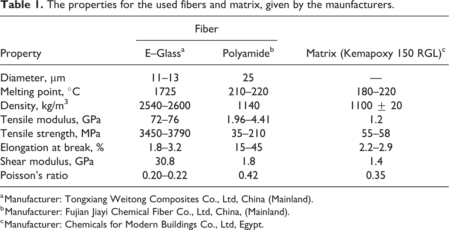
a Manufacturer: Tongxiang Weitong Composites Co., Ltd, China (Mainland).
b Manufacturer: Fujian Jiayi Chemical Fiber Co., Ltd, China, (Mainland).
c Manufacturer: Chemicals for Modern Buildings Co., Ltd, Egypt.
Fabrication of composites
Seven glass–polyamide reinforced epoxy composite laminates with different stacking sequences and different relative fiber amounts were fabricated using the hand layup technique due to its simplicity and minimal infrastructural requirements.
22
More details about the fabrication technique can be found in the literature.
23
–25
All fabricated composite laminates have almost constant overall fiber volume fraction of
Codes and descriptions of the fabricated glass–polyamide reinforced epoxy hybrid composites.
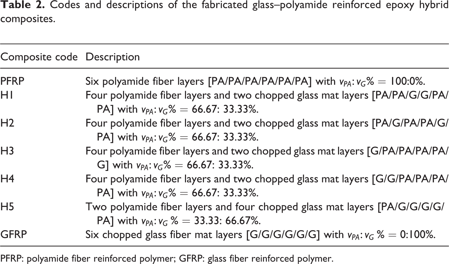
PFRP: polyamide fiber reinforced polymer; GFRP: glass fiber reinforced polymer.
Polyamide fiber bundles were fixed on the wooden templates using small pins, whereas chopped glass mat was cut into
The above procedure was repeated with alternate layers of matrix and fibers until the whole laminate was constructed. When the last fiber layer was impregnated, 25 kg mass was placed on the top of the laminate to obtain a uniform pressure and a constant thickness for the fabricated composite (Figure 1(e)). The final laminate is displayed in Figure 1(f).
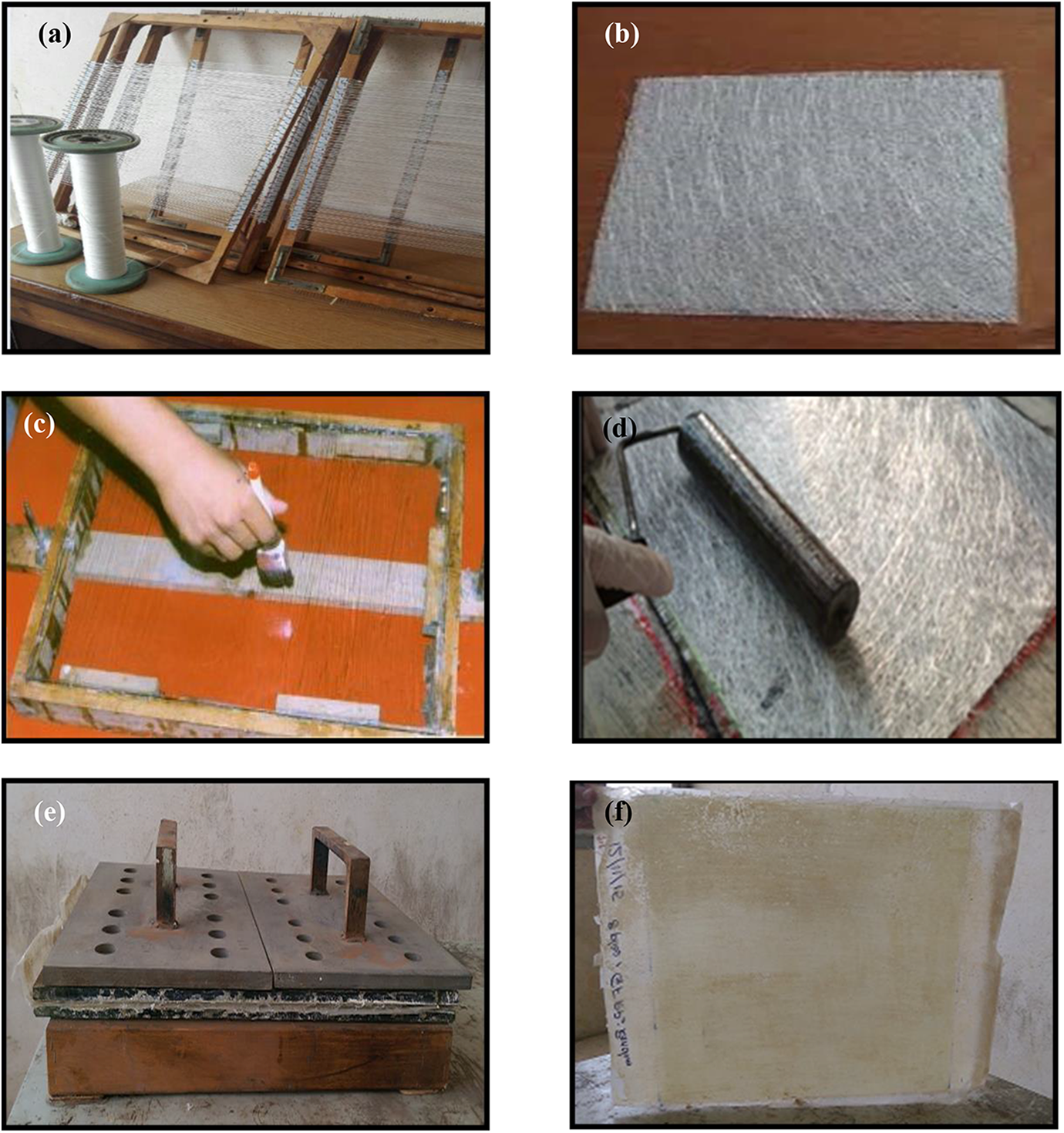
Hand layup fabrication process of glass–polyamide reinforced epoxy hybrid composites.
Testing and measurements
Density and void content
The experimental densities

The theoretical densities

where
The void content in the fabricated composites is determined as follows 27

Water uptake test
Water uptake tests were carried out based on ASTM D5229/D5229M.
28
Specimens with 70 mm length and 15 mm width were immersed in distilled water and sea water at room temperature for 200 days up to the saturation point. Specimens were withdrawn from water from time to time, wiped to remove water droplets, and regularly weighed to measure the weight change during the water uptake process.
29
Water uptake content
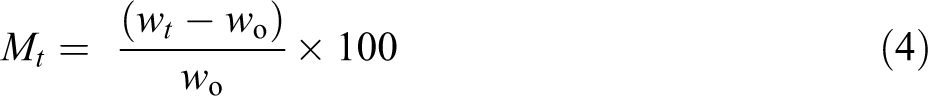
where
The composite diffusion coefficient
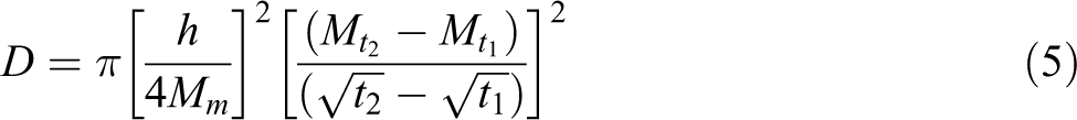
where Mt and Mm are, respectively, the water uptake at time t and the maximum water uptake at equilibrium plateau and h is the specimen thickness.
Since most water diffusion experiments include moisture diffusion through six surfaces, the predicted value of D from equation (5) leads to error.
30
For true one-dimensional diffusion coefficient
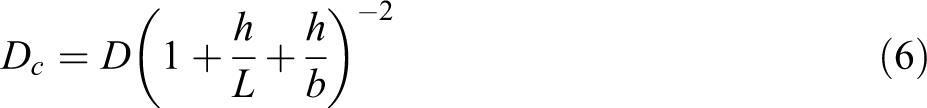
where
Abrasive wear test
Abrasive wear tests were carried out using a pin–on–disc tester at room temperature as per ASTM G 99, 31 see Figure 2. Rectangular specimens with dimensions of 70 × 15 × 2.49 mm3 having a contact area of 37.5 mm2 were fixed in the flexible arm using a holder and loaded against a hardened ground steel disc carried silicon carbide (SiC) abrasive paper of 180 grit. The specimen was held stationary, and the disc was rotated while a normal load was applied through a lever mechanism. A series of tests were conducted with a constant sliding velocity of 0.93 m/s under four different normal loads of 2.5, 5, 7.5, and 10 N. 21,32,33 Thus, the applied pressure was varied from 0.07 MPa to 0.27 MPa. The sliding distance was varied by varying the running time. Each experiment was repeated for three times to ensure the reliability of the results, and the average value was considered. After running each sliding distance test, experiment was interrupted, and the weight of the specimen was measured using an electronic balance with 10−4 g accuracy. The specific wear rate Ws can be calculated as follows
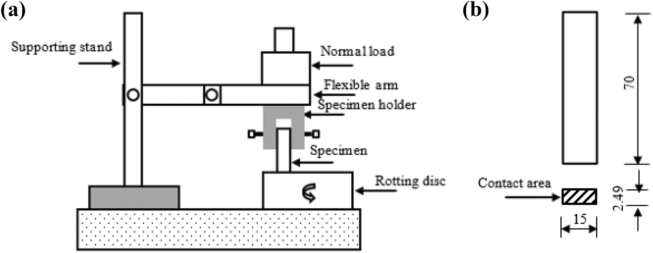
(a) Schematic drawing for the pin–on–disc wear tester and (b) wear specimen. Dims are in mm.
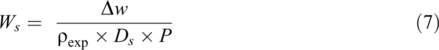
where
Temperature measurement at the specimen pin–disc interface
During testing, temperature at the specimen pin–disc interface has been measured using thermocouples placed at 5 mm away from the pin–disc interface.
SEM studies on worn surfaces
Scanning electron microscopy (SEM) was carried out on the worn surfaces of the studied composites using JSM 6100 scanning electron microscope, JEOL Ltd, Tokyo, Japan. The worn surfaces were coated with a conductive gold layer and kept in an ionizer. Images of worn surfaces were taken by subjecting them to a voltage of 20 kV. The morphologies of worn surfaces were studied to understand the wear mechanism and to find the effect of the hybridization.
Results and discussions
Density and void content
There is a good agreement between the experimental (
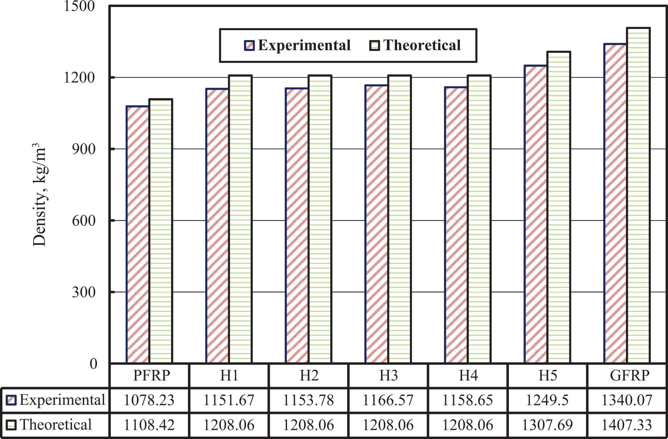
Theoretical and experimental densities of glass–polyamide reinforced epoxy composites.
Void is an important problem that is encountered in fiber–reinforced composites. The most common reason of voids is the incapability of the matrix to displace all air entrained within the fibers as it passes through the matrix impregnation. The presence of voids considerably reduces the mechanical and physical properties of the composites. The void content for studied composites is illustrated in Figure 4. It is obvious that GFRP composite has the highest void content which is about 1.8 times that of PFRP composite. According to De Albuquerque et al.,
34
incomplete wetting out of the fibers by the matrix leads to the formation of voids. As expected, hybrid composites have intermediate void content between PFRP and GFRP. The hand layup technique leads to a satisfactory level of fiber impregnation and results in low void content composites (
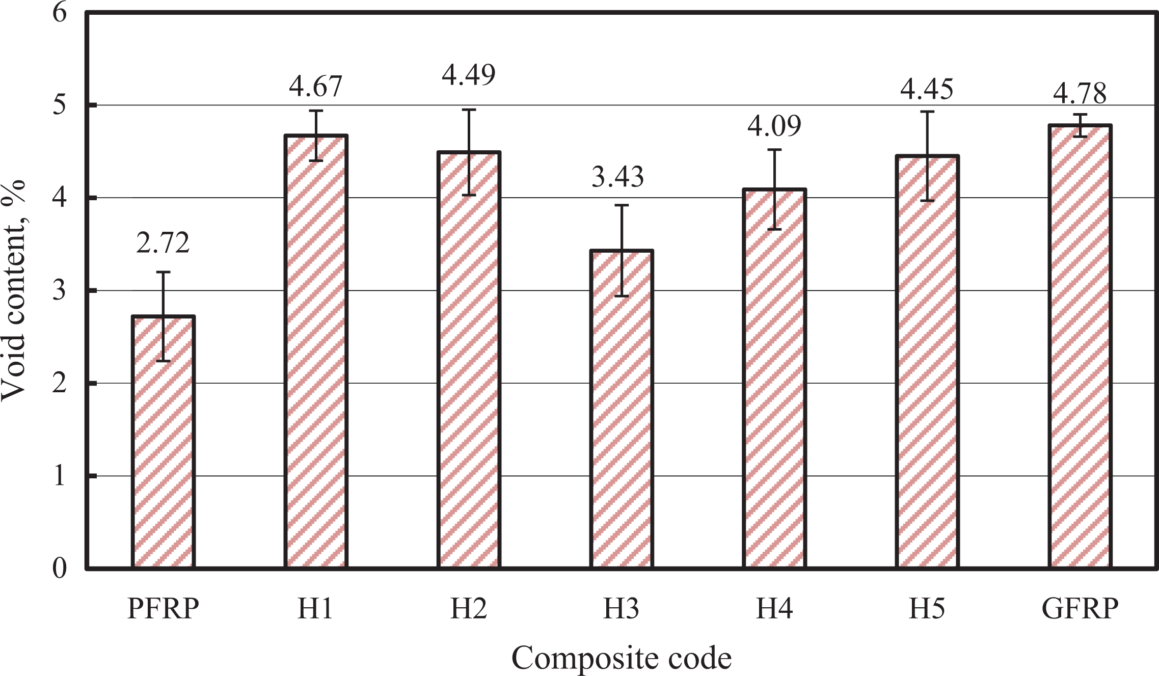
Void content of the fabricated glass–polyamide reinforced epoxy composites.
Water uptake
Figure 5 displays the water uptake versus square root of time for glass–polyamide reinforced epoxy composite specimens. Three samples of each composite type were immersed in distilled water and sea water at room temperature, each for 200 days. It is clear from Figure 5 that the rate of water diffusion is time dependent. All studied composite specimens absorb water very rapidly at the initial stage and later a saturation level is attained without any further increase. The highest water uptake is observed for GFRP composite, while the lowest one is associated with PFRP composite. This is due to the void content in GFRP composite and capillary action when chopped glass fiber ends are exposed to water. 36 Consequently, increasing glass fiber content in hybrid composites increases the capability of water uptake as noticed for H5. This result agrees with that obtained by Rashdi et al. 37 On the other hand, incorporating polyamide fiber to chopped glass mat–reinforced composite makes it more hydrophobic and thus decreases the water uptake. This is due to the fact that during water immersion, water molecules go through the micro–voids formed during the fabrication. Moreover, water molecules rapidly penetrate and diffuse along the interface because of the capillarity. This result agrees with that obtained by Abdelhaleem et al. 38
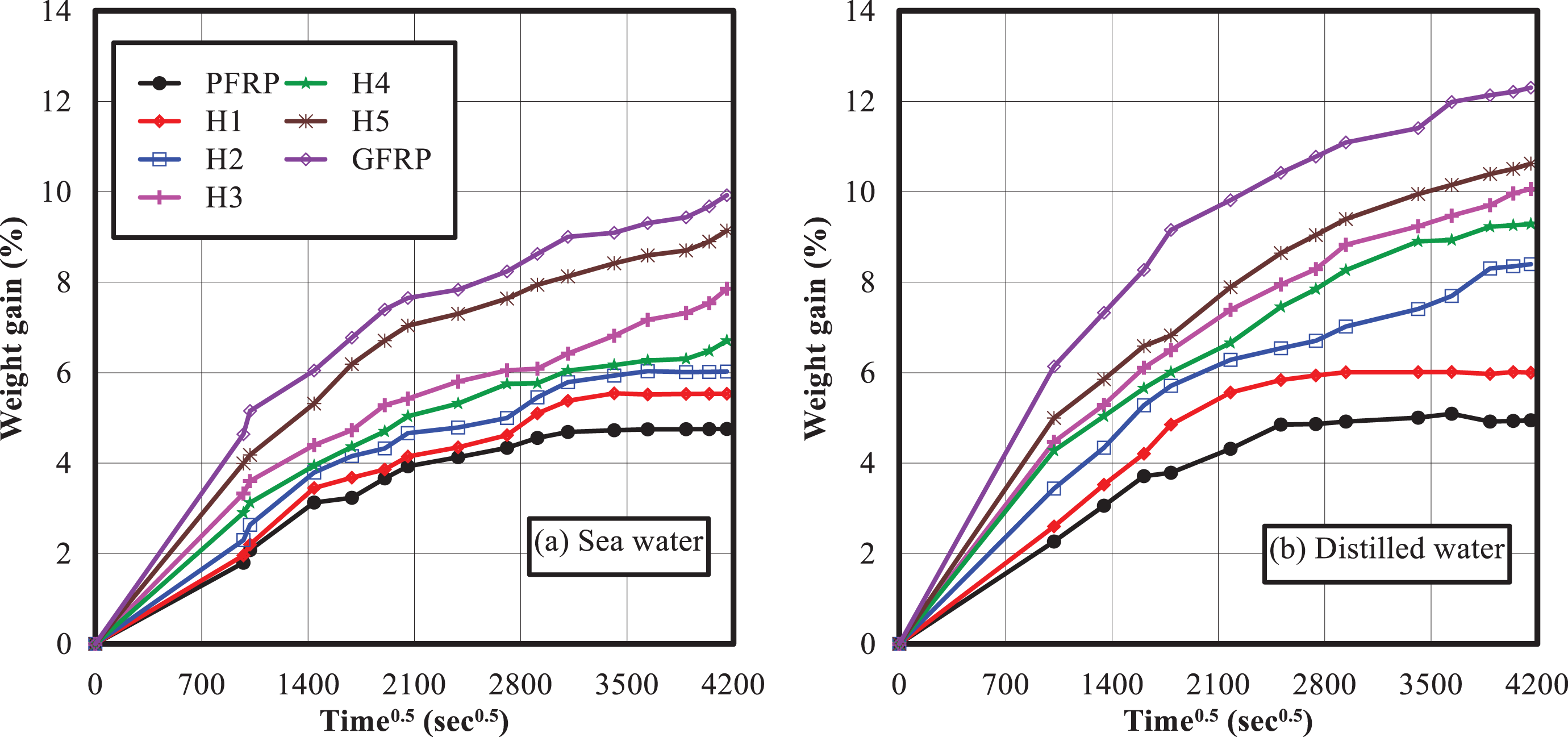
Water uptake of glass–polyamide reinforced epoxy composites.
Furthermore, the better adhesion between matrix and polyamide fiber decreases the velocity of the diffusing molecules. The strong adhesion results in tighter packing within the epoxy–fiber network. Consequently, the distance traveled by the diffusing water molecules between two consecutive collisions would drop and results in lower water uptake. 39 It is clear that the stacking sequence definitely affects the water uptake characteristics, the presence of polyamide fiber at the specimen skin; that is, H1, improve the resistance to water uptake as polyamide fiber works as a barrier to chopped glass mat preventing direct contact between chopped glass mat and water.
Uptake of distilled water is slightly higher than that of sea water for all studied composites due to the presence of ions in salt water. 40 The same finding was recorded by Davies et al. 41 The presence of salt molecules reduces the activity of water molecules and results in addition of salt particles on the surface of specimen which could further inhibit the water uptake. Also, the accumulation of sodium chloride ions on the fabric’s surface for specimens immersed in sea water increases with time and hinders subsequent water diffusion. Void content influences the absorption process, that is, voids accumulate water and, in the case of sea water, form concentrated salt solutions. Also, the interface quality (fiber–matrix interface and the different layers interface) contributes to the water uptake. 42 Although the uptake is greater for distilled water, the saturation time is approximately the same for both conditions. As reported by Abd El-baky, 35,36 the lower trend of sea water uptake can be due to the deposition of trace elements on the surface of composite body which intervene with the diffusion processes.
The diffusion coefficient without and with correction factor was calculated according to equations (5) and (6), respectively, and listed in Table 3. It was noted that the diffusion coefficient for specimens immersed in distilled water is higher than that in sea water. Also, the lowest diffusion coefficient was associated with PFRP, whereas the highest one was observed for GFRP. As expected, diffusion coefficient without correction factor is higher than that with correction factor for all composites. Correction factor decreases the diffusion coefficient by about 24% and 26% for, respectively, PFRP and GFRP composites. These results agree with those reported by Cheour et al., 43 Kumar and Sabeel, 44 and Abd El-baky and Attia. 45 The higher the diffusion coefficient, the lower the resistance to water uptake.
Equilibrium water uptake and diffusion coefficient for glass–polyamide reinforced epoxy composites.
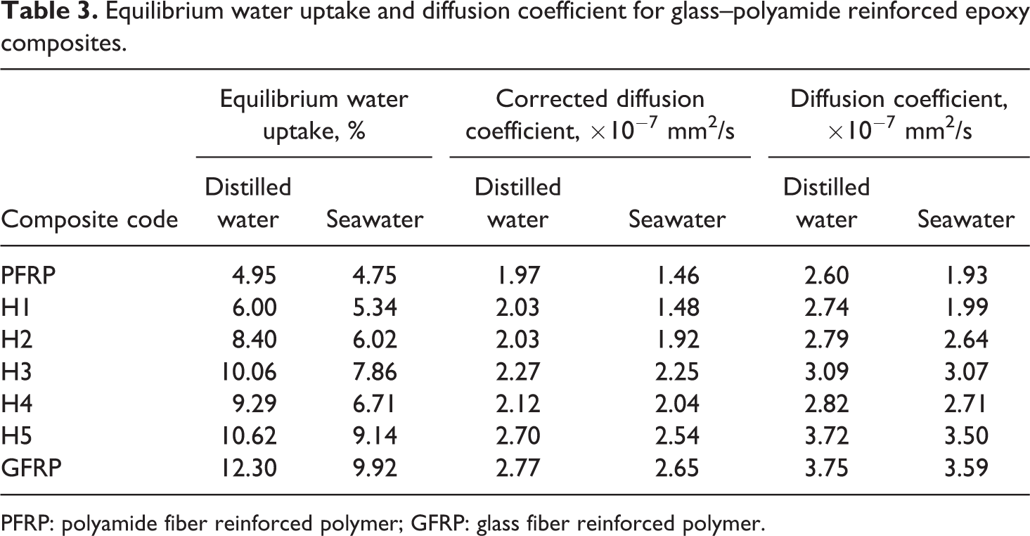
PFRP: polyamide fiber reinforced polymer; GFRP: glass fiber reinforced polymer.
Weight loss due to wear
Figure 6 shows the weight loss versus sliding time for glass–polyamide reinforced epoxy composite specimens under different normal loads of 2.5, 5, 7.5, and 10 N. It was observed that the weight loss increases with increasing applied normal load and the sliding time. This result agrees with that obtained by Gouda et al. 46 That is because, as the load increases, the frictional forces increase (due to the critical surface energy) causing a temperature rise and a decrease in the hardness of the matrix surface. The temperature increase leads to a relaxation in polymer molecule chains, and hence the bond at fiber–matrix gets weakened. Moreover, fibers are broken into fragments and form debris with matrix particles. Hence, wear is increased. Moreover, the increase in the normal load will increase the contact stresses, which in turn causes brittle failure of fibers on the specimen surface and severe material removal. 47
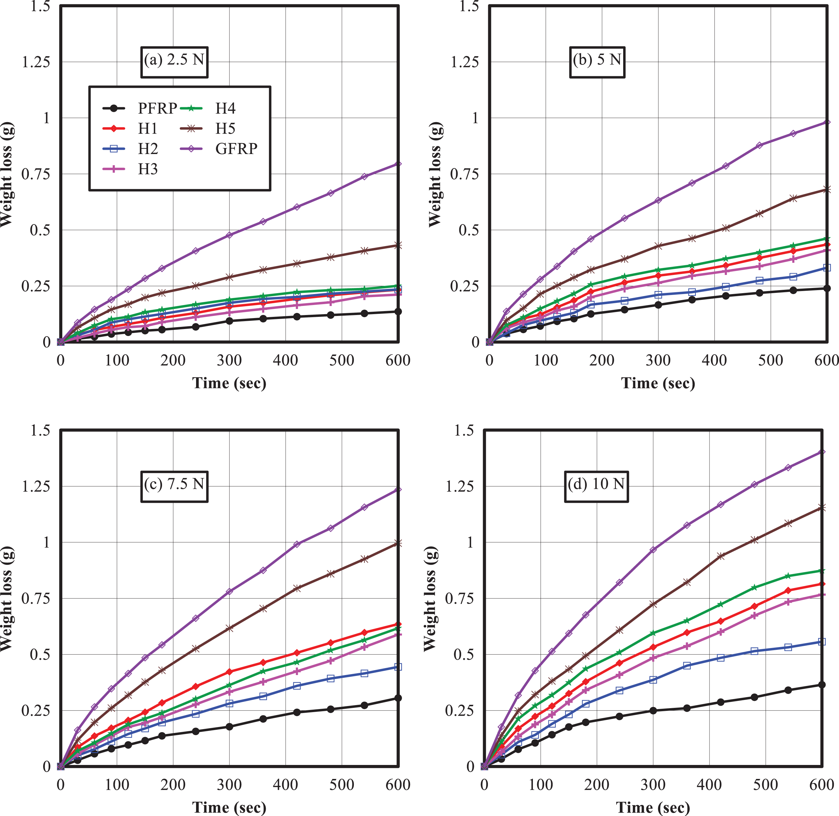
Wear behavior of glass–polyamide reinforced epoxy composites under different normal loads.
As shown in Figure 6, weight loss is relatively low at the lowest normal load (2.5 N) because of the lower penetration and less number of abrasive particles in action with the rubbing surface. Abrasion wear greatly increases with increasing the normal load because most of the abrasive particles penetrate into the surface and create more grooves, resulting in more material removal by ploughing. 48 The increased weight loss at the highest normal load (10 N) may be attributed to fiber pullout, matrix cracking, and fiber–matrix debonding occurred as a result of wear test. This result agrees with that obtained by Megahed et al. 33
PFRP composite specimens show the highest wear resistance compared to the other types containing glass fiber. This is mainly attributed to the high wear resistance of polyamide fiber. The high stiffness of glass fiber and its brittle nature makes it more prone to break under severe wear conditions than polyamide fiber. 49 H1–H5 hybrid composites display intermediate weight loss between PFRP and GFRP composites. All hybrids have better wear resistance than GFRP composite specimens due to the addition of ductile and wear resistant polyamide fiber. It is important to emphasize that the stacking sequence has a slight effect on the weight loss whilst the relative fiber amounts have a noticeable effect as shown in Figures 6 and 7. As polyamide fiber amount increases, the weight loss decreases. It means that polyamide fiber is very effective in improving the tribological performance of glass fiber–reinforced composites.
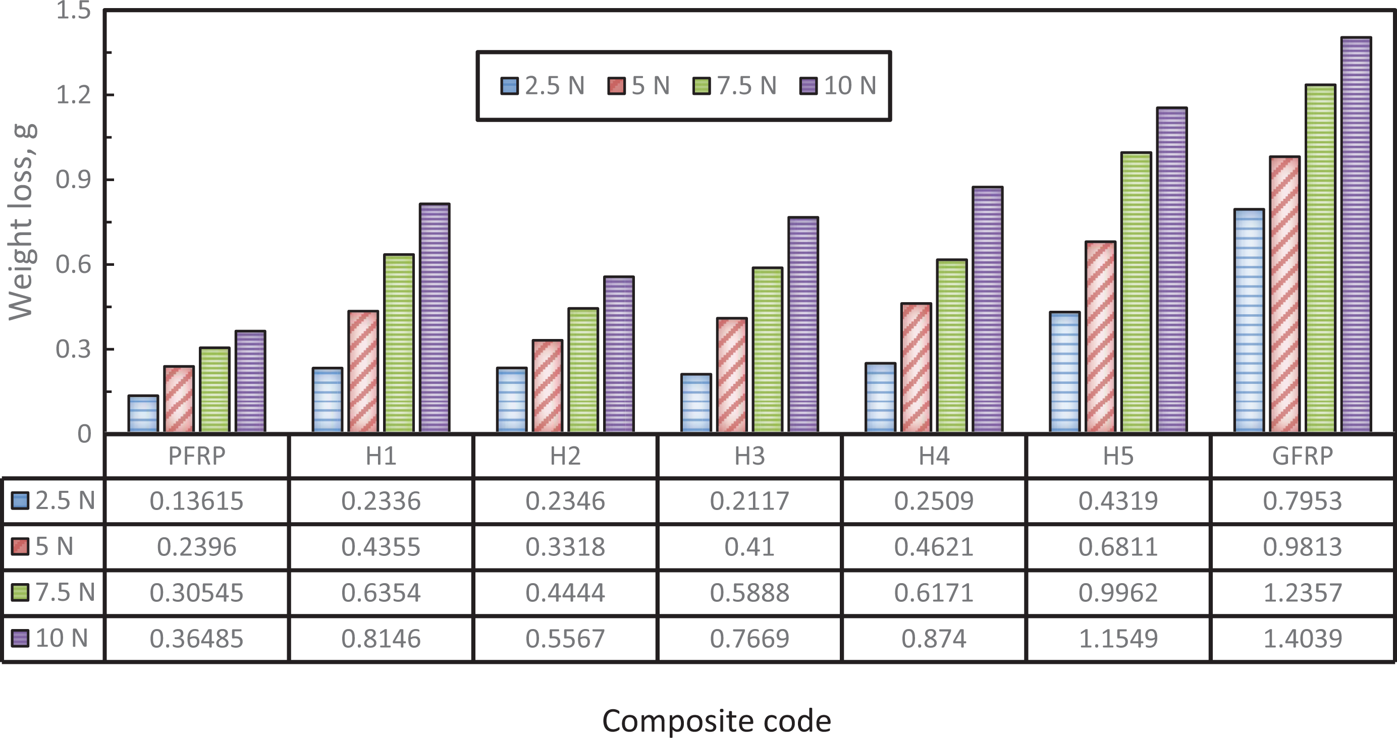
Effect of normal load on wear resistance of glass–polyamide reinforced epoxy composites.
At low applied loads, that is, 2.5 and 5 N, the stacking sequence has insignificant effect on weight loss. As the applied load increases, the stacking sequence effect on weight loss becomes clearer. It was obvious that at 7.5 and 10 N, H2 composite has the lowest wear resistance due to fiber–matrix debonding.
Water aging effect
Figure 8 shows the weight loss versus sliding time for glass–polyamide reinforced epoxy composite aged specimens under applied load of 5 N. It is clear that, weight loss for specimens aged in sea water not seawater is higher than that in distilled water. Figure 9 shows the weight loss for dry and wet glass–polyamide reinforced epoxy composite specimens. Water uptake appears to positively affect the weight loss of the studied composites. This increase in weight loss is due to water diffusion along the interface between polyamide and glass fiber layers and epoxy matrix. The presence of water at the interface weakens the interfacial bond, which in turn accelerates the failure process. According to Dhakal et al, 50 once the water is absorbed, it causes swelling in fibers, creates micro–cracks, causes debonding and weakens fiber–matrix interface. Water absorption during loading considerably accelerates crack initiation and propagation. This result agrees with that obtained by Mohan and Kanny 16 and Nguong et al. 51
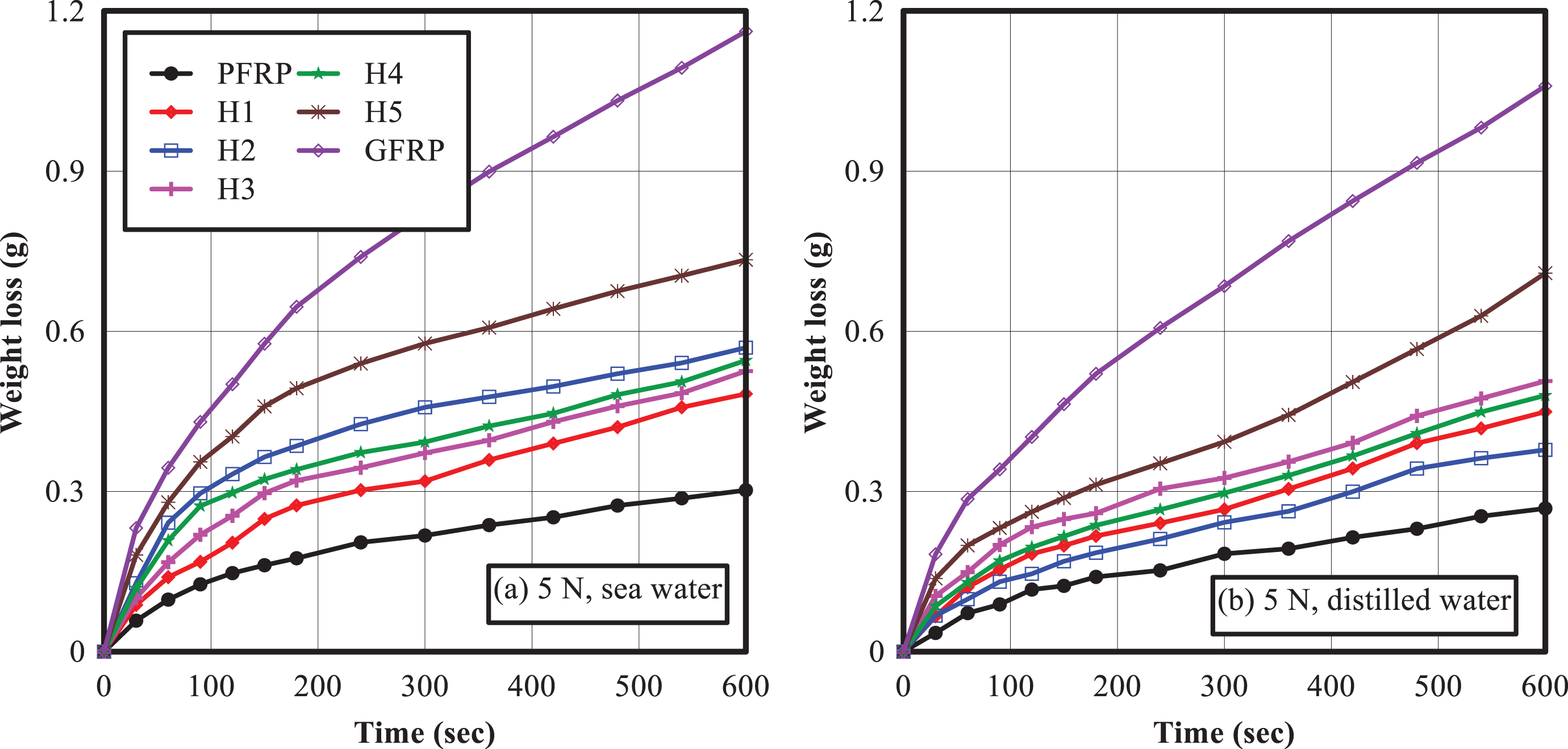
Wear behavior of glass–polyamide reinforced epoxy composites under aging conditions.
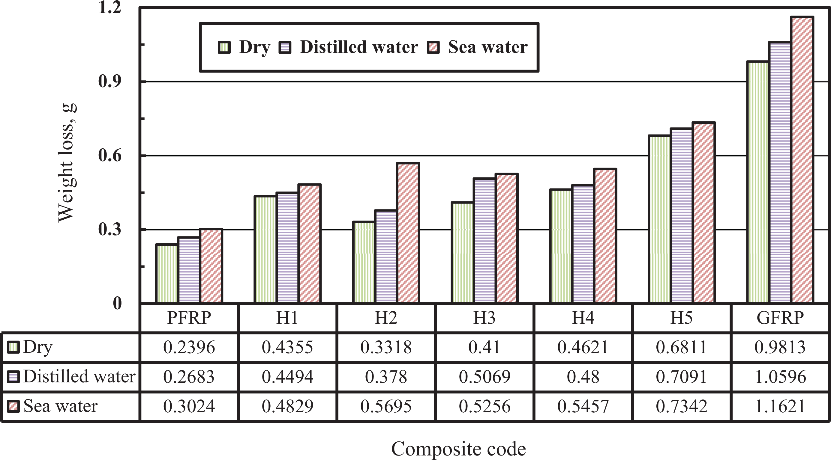
Effect of water aging on weight loss of glass–polyamide reinforced epoxy composites.
Specific wear rate
Figure 10 shows the specific wear rate against the sliding distance. Maximum specific wear rate was noticed at the beginning of the experiment because the abrasive paper was fresh. With consecutive runs, the specific wear rate decreased gradually because the abrasive grits became smooth and less effective. The wear debris fill the space between the abrasives, which reduced the depth of penetration in the specimens. At a certain stage, a steady state for specific wear rate was noticed. This steady–state condition is probably due to the transfer film of polymer onto the counter abrasives. 52,53 Also, this is due to the fact that initially only the specimen and rotating disc with abrasive paper are in contact with each other which result in asperities physically interlocking into the crevices. Now, as the disc starts rotating, even on application of low load, the asperities deform plastically due to shearing. As a result, weight loss is too high at the starting of the experiment. This result agrees with that obtained by Debnath et al. 54
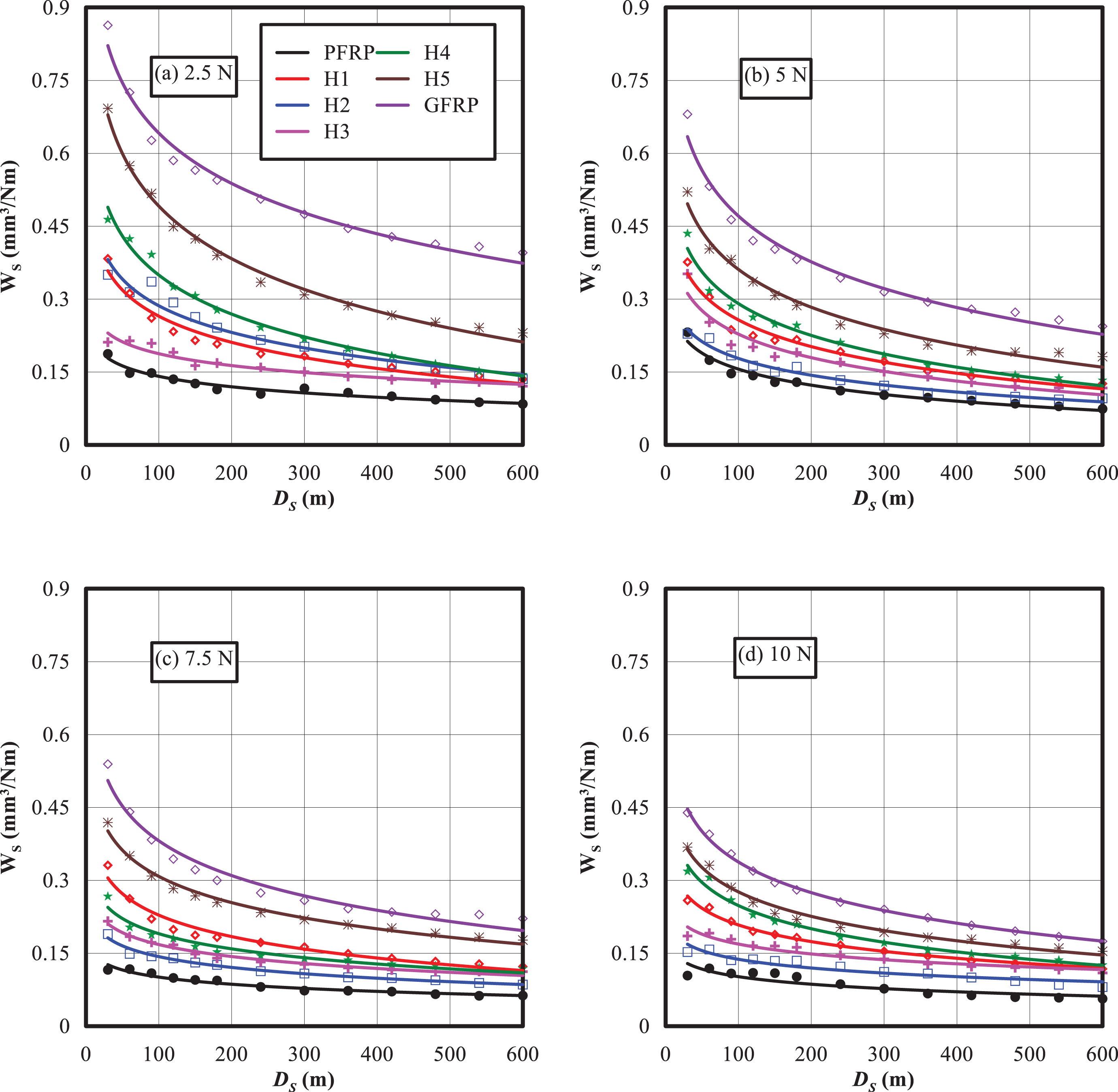
Specific wear rate under different normal loads for glass–polyamide reinforced epoxy composites.
Figure 10 and Table 4 show that the specific wear decreases with increasing the applied load. This result agrees well with that obtained by Srinivasa and Bhagyashekar. 55 The highest specific wear rate was observed for GFRP, while the lowest was associated with PFRP composite under different applied loads. As glass content increases, the specific wear rate increases.
Specific wear value at DS = 600 m and temperature rise close to specimen pin–disc interface for glass–polyamide reinforced epoxy composites.
PFRP: polyamide fiber reinforced polymer; GFRP: glass fiber reinforced polymer.
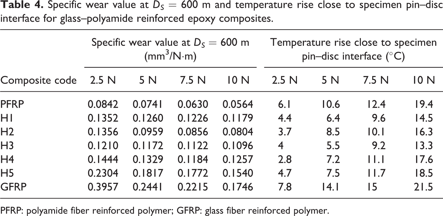
Temperature measurement near the interface
Figure 11 shows the temperature rise close to specimen pin–disc interface versus the sliding time. It was observed that as the sliding time and applied load increase, the temperature rise at the specimen pin–disc interface increases. When the specimen slides against the disc with SiC abrasive paper, heat is generated due to work being done against friction. The heat generation manifests as a raise of temperature thereby affecting the material’s properties which could lead to the failure of the specimen’s sliding surface. 7 It is clear from Table 4 that the maximum temperature rise (21.5°C) was noticed for glass/epoxy composite. As glass fiber content increases, the temperature rise increases.
Temperature measurement rise close to specimen pin–disc interface for glass–polyamide reinforced epoxy composite specimens during wear test.
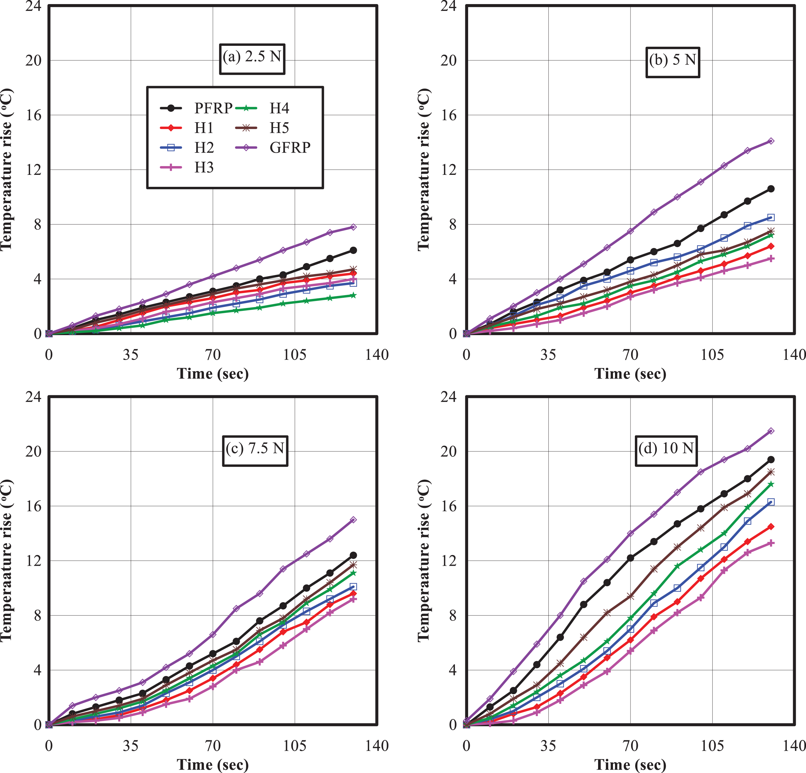
SEM of worn surface
Figures 12 –14 show the images of worn surfaces of glass–polyamide reinforced epoxy composites. The presented worn surface images are for applied load of 10 N. Figure 12 is an image of glass/epoxy composite showing severe wear of the surface. Severe damage is characterized by the disintegration of the surface, matrix cracking, fiber fracture, fiber–matrix debonding, wear debris, and deep grooves. Whereas for glass–polyamide/epoxy composites shown in Figure 13, the surface is much smoother as the load is shared by polyamide which is more resistant to wear abrasion. A mixture of matrix cracking, glass fiber breakage, and polyamide fiber pull out was noticed. Figure 14 shows polyamide/epoxy worn surface which is smoother than the abovementioned surfaces. It is clear that there is a good interfacial bonding between polyamide fiber and epoxy matrix in PFRP composite. Polyamide/epoxy worn surface has less wear and free from scars. This surface is associated with the lowest specific wear compared to other compositions. This is due to the presence of polyamide fiber which makes the surface much stronger and resists the repeated shear loading during wear. Further, it can be concluded that the addition of polyamide fiber to glass/epoxy composite reduces the severe wear and converts it to a milder one, which is evident from the worn surface images.
SEM representing the worn surface of glass reinforced epoxy composite.
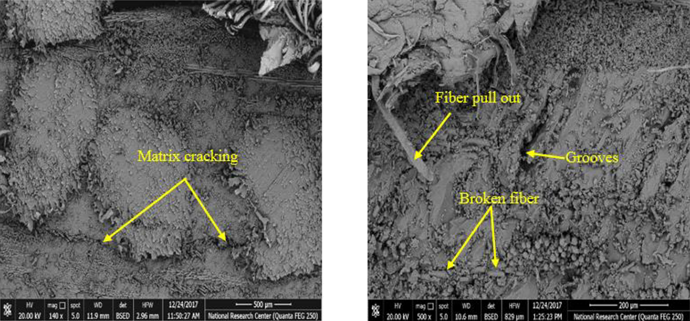
SEM representing the worn surface of glass–polyamide reinforced epoxy hybrid composites.
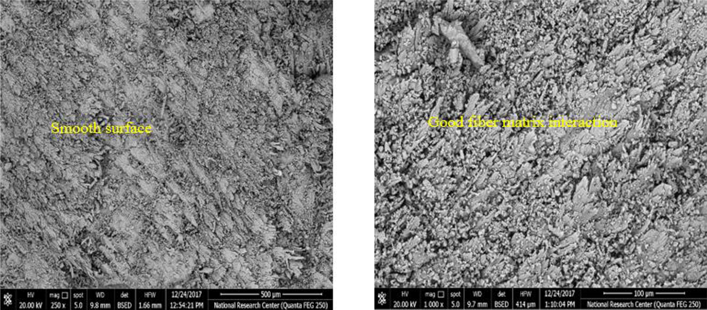
SEM representing the worn surface of polyamide reinforced epoxy composite.
Conclusions
The wear performance of glass–polyamide reinforced epoxy hybrid composites was investigated experimentally using a pin–on–disc tester taking into account the effect of water absorption. The composites were fabricated using the hand layup technique. Specimens were immersed in distilled water and sea water for 200 days at room temperature. The effects of reinforcement hybridization, stacking sequence and relative fiber amounts on wear properties of dry and wet specimens were studied. Temperature rise close to specimen pin–disc interface has been measured. The following findings have been obtained:
When the applied load and the sliding time increase, the wear rate increases. The addition of polyamide fiber layers into chopped glass mat–reinforced composite noticeably enhances its wear resistance. Stacking sequence has a slight effect on the wear resistance, whereas relative fiber amounts have a great effect. As polyamide fiber content increases, the wear resistance is improved.
The water uptake of the fabricated composites was found to increase with increasing chopped glass mat amount. The existence of polyamide fiber at the outer layers of the composite decreases the water uptake. For the studied composites, distilled water uptake is slightly higher than that of sea water. Besides, immersing the specimens in distilled water or sea water has reduced the wear resistance. The amount of water absorbed and wear resistance can be effectively controlled by changing the stacking sequence and relative fiber amounts.
The maximum temperature rise close to specimen pin–disc interface was noticed for GFRP composite under 10 N to be (21.5°C). As the applied load and the sliding time increases, the temperature rise increases.
SEM of worn surfaces shows severe damage characterized by the disintegration of the surface, matrix cracking, fiber fracture, fiber–matrix debonding, wear debris, and deep grooves for glass fiber/epoxy composite, while polyamide fiber/epoxy surface has less wear and free from scars. A mixture of matrix cracking, glass fiber breakage, and polyamide fiber pull out was noticed for worn surfaces of hybrid composites.
The proposed hybrid composites can be used in tribological applications such as sliding elements, sliding bearings, seals, conveyors, clutches, tires, and brakes.