
Abstract
The effect of water aging on the impact performance of glass (G)–polypropylene (P)-reinforced epoxy composites was investigated. Specimens were fabricated using the hand layup process with constant overall fiber volume fraction. Specimens were immersed in distilled water and seawater at room temperature, until reaching their water content saturation point. The dry and water-immersed specimens were subjected to edge-wise and flat-wise impact tests. Fractured surfaces were examined using scanning electron microscopy, SEM. The results showed that the impact performance of G-reinforced epoxy composite has been enhanced through hybridizing it with P-fiber but water uptake has been increased. Water uptake reduces the impact strength of all tested specimens. Composites exposed to seawater absorb less water than those exposed to distilled water. The water absorption percentage and impact performance can be effectively controlled by changing the hybrid configuration, plies stacking sequence and P/G fiber ratio.
Introduction
Polymer composites are recommended for being used in outdoor applications and marine infrastructures. Also, they have gathered tremendous attention in water storage vessels, desalination plants, ship building industry, and manufacture of leisure boats due to their excellent corrosion resistance and lightweight property, (refer to the works of Shubhra et al. 1 and Chakraverty et al. 2 ). All polymer composites absorb moisture in humid atmosphere and when immersed in water. The moisture absorption leads to a degradation in the fiber–matrix interface region, creating poor stress transfer efficiencies and resulting in a reduction in the mechanical and dimensional properties (refer to the works of Kootsookos and Mouritz 3 and Dhakal et al. 4 ).
Water absorption of composites is a complex behavior, which can be influenced by many factors, such as the resin and fiber types, fiber volume fraction, void content, and fabrication process (refer to the works of Buehler and Seferis 5 and Perrin et al. 6 ). Moisture diffusion in polymer composites is governed by three different mechanisms. The first involves diffusion of water molecules inside the micro-gaps between polymer chains. The second involves capillary transport into the gaps and flaws at the interfaces between fiber and matrix. The third involves transport of micro-cracks in matrix arising from fiber swelling (refer to the work of Espert et al. 7 ).
Various studies have been reported on the effect of water uptake on the mechanical properties of polymer composites. Kootsookos and Mouritz 3 found that glass fiber composites absorb more moisture than carbon fiber ones. The mode I interlaminar fracture toughness of composites is not affected significantly by seawater immersion, although the flexural stiffness and strength decrease with increasing the amount of water absorption. Gu 8 reported a decreasing trend in the tensile and bending strength of glass/polyester seawater-treated samples. Bian et al. 9 revealed that the tensile, flexural, and interlaminar shear strengths of glass fiber/epoxy composite specimens after 42 days of immersion had decreased by 13, 43, and 50%, respectively.
Other studies were carried out on the effect of water uptake on the mechanical properties of hybrid polymer composites based on natural–synthetic fibers. Silva et al. 10 found that the more affected properties of curaua/glass hybrid composites are the flexural modulus for seawater immersion and the tensile strength for distilled water immersion. Zamri et al. 11 reported that the flexural and compression properties of jute-glass fibers-reinforced polyester hybrid composites decrease with increasing the percentage of water uptake. Ghani et al. 12 noticed a decrease in the tensile modulus of kenaf–glass fibers–reinforced polyester hybrid composites. Strain to failure has been improved by the inclusion of kenaf fiber in fiber glass reinforced composite until certain limit of water absorption (third week immersion).
Overlooking the aforementioned literature, no work dealing with the effect of water uptake on the mechanical behavior, especially the impact performance, of hybrid polymer composites based on synthetic fibers (G and P fibers) is found. So in this research, G–P fibers–reinforced epoxy composite laminates fabricated using the hand layup process with different configurations, layups, and P/G fiber ratio were subjected to impact loading in edge-wise and flat-wise directions. Water absorption of the fabricated composites was found out by the measurement of the relative weight uptake of the aged specimens in accordance with time. The effect of water uptake on the impact performance of fabricated hybrids has been studied. SEM adjacent two pins in the wooden frame is called has been used to investigate the specimens’ failure mechanisms.
Experimental work
Materials
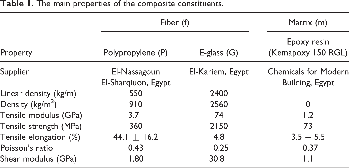
The mechanical and physical characteristics of the constituent materials used in the fabrication of hybrid composites are listed in Table 1.
The main properties of the composite constituents.
Composite specimens’ preparation
The hand layup process was used to fabricate a total of nine G–P-reinforced epoxy composite laminates. Owing to the simplicity and minimal infrastructural requirement of the hand layup fabrication process, it has been used by several researchers, including Selmy et al. 13,14 and Attia et al. 15 The overall fiber volume fraction, that is, Vf = VfP + VfG, and thickness of all fabricated composites are approximately 32.5% and 7.25 mm, respectively. First, G- and P-fiber bundles were fixed on wooden frames using small pins (see Figure 1(a)). The distance between each adjacent two pins in the wooden frame is called the pitch. As shown in Table 1, the densities of G and P fibers are 2560 and 910 kg/m3, respectively. The G- and P-fiber volume fraction of fabricated composites can be controlled by changing the pitch value as shown in Table 2. Arranging the fiber bundles with this method ensures regular distribution of fibers and keeps fibers’ place.
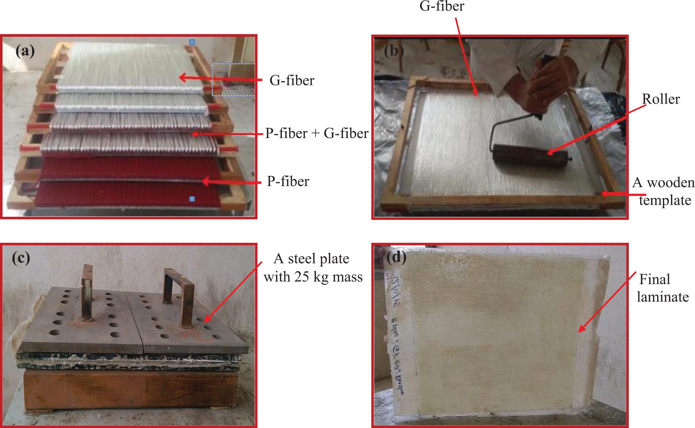
(a) G and P fibers fixed on the templates, (b) the rolling process, (c) a 25-kg steel plate placed on the top of the laminate, and (d) a final composite laminate (refer to the work of Abd El-baky et al. 16 ).
The details of the fabricated G–P fibers–reinforced epoxy hybrid composites.
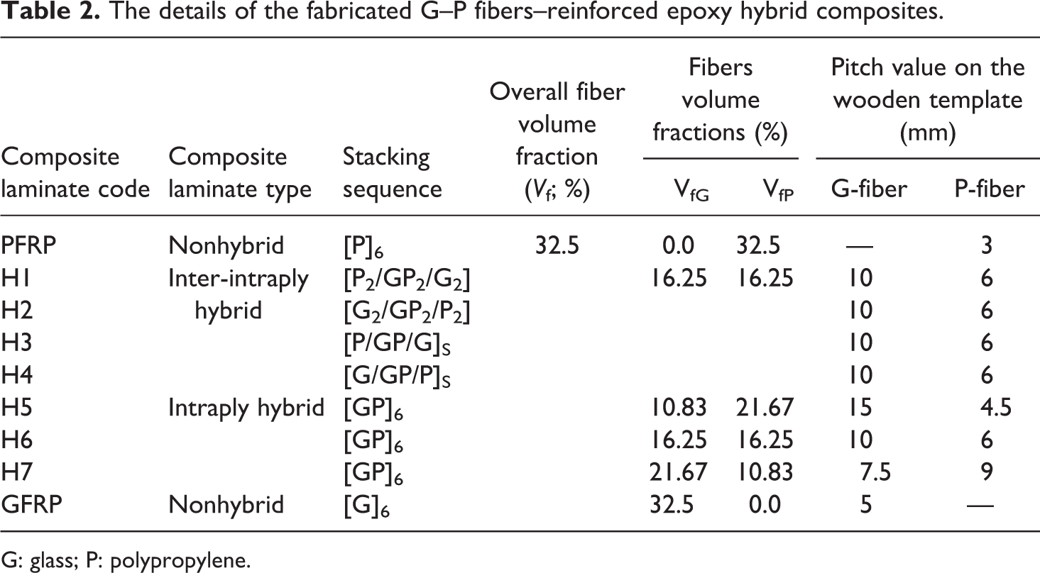
G: glass; P: polypropylene.
The details of fabricated composite laminates, their configuration, stacking sequence, and fibers’ relative volume fractions are listed in Table 2. The fabrication process of G–P fibers/epoxy composite laminates can be summarized as follows.
The layup mold was treated by a release agent and was left to dry in air. A layer of epoxy matrix repeated with alternate layers of was spread on the mold. The first template with fiber bundles was placed on the resin. Then they were rolled to distribute the matrix and displace the air outward (see Figure 1(b)). When the fibers were fully impregnated with epoxy, they were loosen from the template. Another amount of epoxy was added and distributed. The procedure was repeated with alternate layers of fibers and matrix until the whole laminate was constructed. When the last fiber layer was impregnated, a steel plate with 25 kg mass was placed on the top of the laminate to obtain a uniform pressure and consequently a constant thickness for the fabricated composite (see Figure 1(c)). Then the fabricated laminate was left at room temperature till it completely cured (Figure 1(d)). The test specimens were prepared according to the concerning standards.
Water absorption test
Water absorption of the fabricated composites was found out using equation (1) by measuring the relative weight uptake of the aged specimens in accordance with the exposure time as per ASTM D570. 17 The specimens were cut into 50 × 50 mm2. Then they were weighted and immersed in distilled water and seawater baths at ambient temperature. From time to time, the specimens were pulled out of water, dried with paper tissue, and weighed immediately before reimmersion in water (refer to the works of Abd El-baky and Attia 18 )

where Pw and Pd are the wet and dry weights of the sample, respectively.
Izod impact test
The impact testing was carried out according to ISO 180 19 by Avery Dennison Pendulum Izod Impact System. The impact velocity was 3.65 m/s. Dimensions of the specimens were 64 × 12.7 mm2. Five replicates were evaluated for each type of samples to obtain impact strength. This test measures the absorbed energy needed to initiate and propagate the specimen fracture. Two types of tests were performed; on the one hand, unnotched specimens were impacted in the flat-wise direction, perpendicular to the layers; on the other hand, notched specimens were impacted in the edge-wise direction, parallel to the layers. For notched specimens, a 45° V-notch was inserted through the specimen thickness by the milling process to a depth of 2.5 mm and the hummer was released. The notched (Sn) and unnotched (Su) impact strengths were calculated by dividing the recorded absorbed energy through the cross section of the specimens as described in the following equations
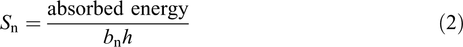

where b, bn, and h are, respectively, the width, residual width after inserting the notch, and thickness of the specimen.
Scanning electron microscopy (SEM)
In order to understand the effect of water absorption on the microstructure of the impacted specimens, the fractured surfaces of dry and water immersed specimens were examined using a scanning electron microscope JSM 6100. Fractured specimens were coated with gold and kept in an ionizer. Images of the fractured specimens were taken by subjecting them to a voltage of 20 kV.
Theoretical work
Fiber volume fraction (Vf) determination
The overall fiber volume fraction of fabricated composites was obtained as follows (refer to the work of Selmy et al.
20
): A piece from the fabricated composite was considered and its volume was calculated (VC). The length of the fiber bundles in all layers (L) was determined. The weight of the fiber in the piece (Mf) was calculated as follows

The fiber volume was calculated as follows
where ρl and ρf are the linear and volumetric densities of the used fiber.
The estimated fiber volume fraction (Vf) was calculated as follows
Void content
The void content is the most important problem that may be encountered in fiber-reinforced polymer composites due to the incapability of the matrix to displace all the air entrained within the fibers as it passes through the matrix impregnation. The existence of voids in the composite significantly reduces its mechanical and physical properties (refer to the work of Abd El-baky 21 ). The void content in the fabricated composites was calculated according to ASTM D2734 22 using the following equation

The theoretical and experimental densities ρth and ρexp, respectively, of the fabricated composites can be expressed using the following equation

where V is the volume fraction, the subscripts “m,” “fP,” and “fG” refer to the matrix, polypropylene fiber, and glass fiber, respectively
where ρ0 is the water density, and Pd and Pim are the sample weight in air and in water, respectively.
Results and discussions
Fiber volume fraction
The overall fiber volume fraction and the G and P-fibers contents were calculated theoretically and listed in Table 2.
Density and void content
There is a good agreement between the experimental and theoretical densities for all fabricated composites as shown in Figure 2. It is clear that, thelower density compared to composite density decreases with increasing P-fiber content due to its lower density compared to G-fiber as indicated in Table 1. Stacking sequence has a slight effect on the density of fabricated hybrid composites.
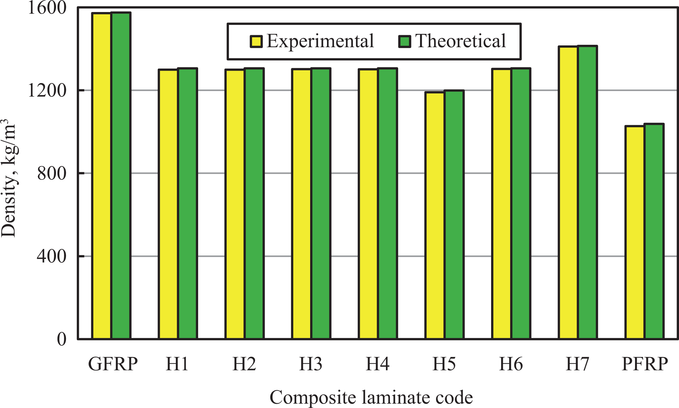
Experimental and theoretical densities of G–P fibers–reinforced epoxy composite specimens.
The void content of fabricated composites is shown in Figure 3. It is clear that polypropylene composite, Polypropylene fiber reinforced polymer (PFRP), presents the highest void content (1.06%) compared to the other composites. This is due to the incompatibility between the epoxy matrix and P-fiber. As reported by de Albuquerque et al., 23 the incomplete wetting out of the fibers with the matrix leads to the voids formation. The lowest void content (0.19%) was associated with glass fiber reinforced polymer composite, Glass fiber reinforced polymer (GFRP). Hybrid composites have intermediate void content between the parent materials, that is, PFRP and GFRP composites. For intraply hybrid composites, as P/G fiber ratio increases, the void content increases. For inter-intraply hybrid composites, the plies stacking sequence has a noticeable effect on the void content. The composite with G-fiber at the periphery and P-fiber at the core, that is, H4 has higher void content (0.36%) compared with the one with the opposite arrangement, that is, H3 (0.3%). That is because P-fiber in the specimen core is tightly packed by G-fiber.
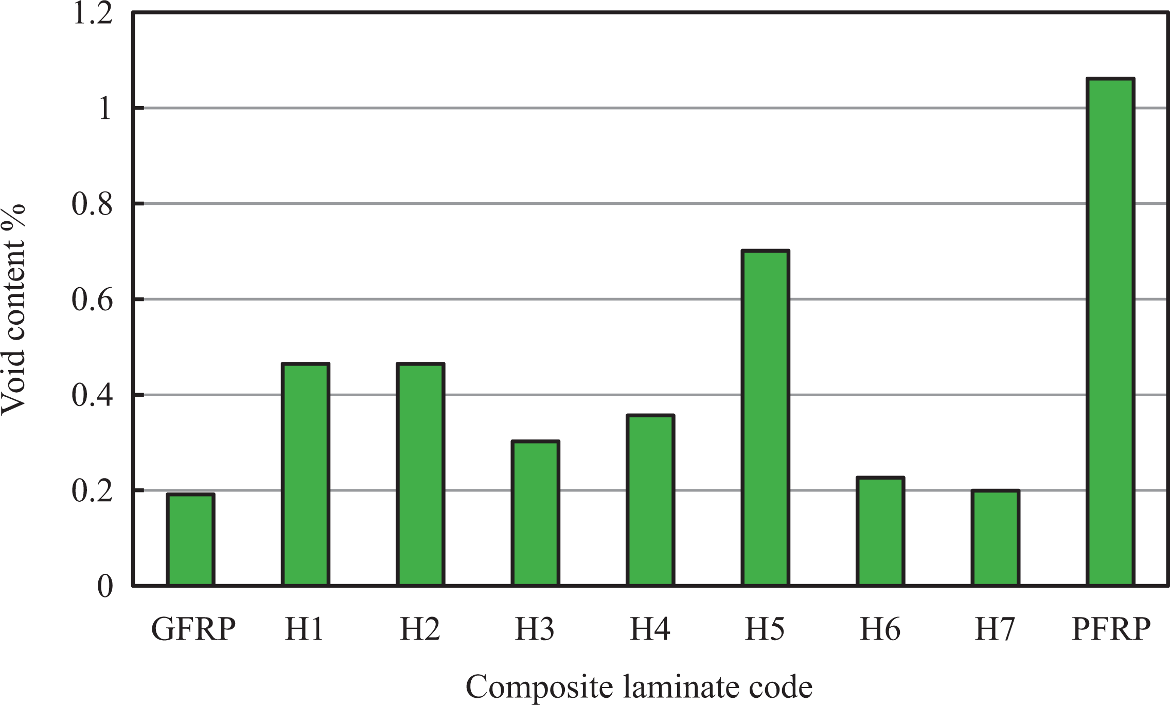
Void content for G–P fibers–reinforced epoxy composite specimens.
Water absorption
The saturation curves of G–P fibers–reinforced epoxy composite laminates in both aging conditions (distilled water and seawater) are presented in Figure 4. The same behavior was observed, all specimens absorb water very rapidly during the first stages (0–25 days for specimens immersed in distilled water and 0–45 days for specimens immersed in seawater). After that, the rate of water diffusion decreases till it reaches the saturation points, where no more water is absorbed. This result agrees with that reported by Kim and Seo. 24
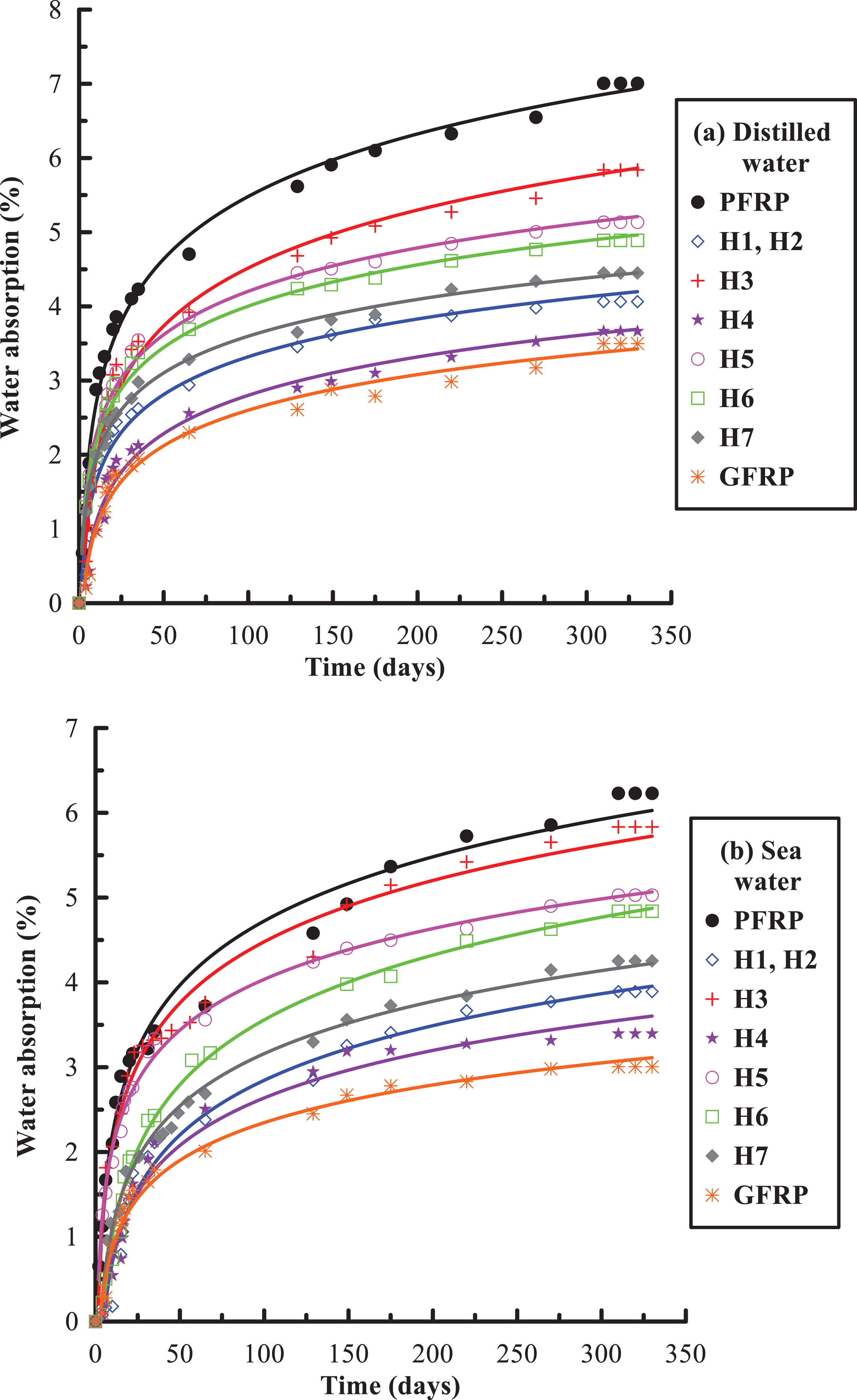
Water absorption of G–P fibers–reinforced epoxy composite specimens.
Water uptake of PFRP composite is the highest while that of GFRP composites is the lowest. This could be possible due to the existence of voids formed during processing and the capillary paths that could accelerate the diffusion in this case, that is, PFRP. It seems to be that what really influences the moisture absorption behavior regarding the nature of fibers is the compatibilization between fibers and matrix. This agrees with that obtained by Espert et al. 7
Hybrid composites have intermediate water absorption properties between those of PFRP and GFRP ones. Water absorption of P-fiber reinforced composites decreases by the addition of G-fiber due to the lower void content. Distilled water uptake is slightly higher than seawater uptake for all studied composites. This happens because of the accumulation of great sodium chloride ions in the fiber’s surface immersed in seawater, which increases with time and hinders subsequent water diffusion. It is interesting to observe that although the absorption is greater for distilled water, the saturation time was approximately the same for both conditions. The presence of voids in the laminated layers also influences the absorption process. Voids can accumulate water and, in the case of seawater, form concentrated salt solutions. Other factors, such as, fiber/matrix interface quality, and interface quality between the different layers i.e. G-fiber and P-fiber layers influence the absorption process, but it is difficult to analyze each one separately. These results agree well with those obtained by Davies et al. 25 and Silva et al. 10 Ingression of distilled water into the matrix polymer is quite more feasible than that of seawater due to the presence of dissolved salts. A concentration-driven osmotic pressure causing moisture ingression in to the polymeric composite body is less of a problem in saline solutions than in distilled water. The bulky nature of various salt components of seawater, with their osmotic effect, influences the rate of moisture ingression with time. The lower trend of moisture gain may be due to the deposition of trace elements on the surface of composite body which intervene with the diffusion processes. This result agrees with that obtained by Silva et al. 10
As reported by Tsenoglou et al., 26 Huang and Sun, 27 and Visco et al., 28 the water diffusion is governed by three mechanisms. First, water molecules diffuse into the matrix. Second, the fiber/matrix interface capillarity effect speeds up diffusion of water molecules. Third, void and micro-cracks in composites store water and increase water absorption. GFRP has higher interlaminar shear strength than PFRP as reported by Attia et al. 15 This result indicates that for GFRP composite, it is the matrix that absorbs moisture, whereas for the PFRP and other hybrid composites, the weak interface speeds up the water absorption and it is called as the “interface-dominated” mechanism. This result agrees with Pavlidou and Papaspyrides. 29
Impact strength
Impact strength is an important property that gives an indication of overall material toughness. Impact strength of fiber-reinforced polymer is governed by the matrix–fiber interfacial bonding, and the properties of both matrix and fiber. When composites undergo a sudden force, the impact energy is dissipated by the combination of fiber pullouts, fiber fracture, and matrix deformation (refer to the work of Wambua et al. 30 ). Figure 5 shows that edge-wise and flat-wise impact strengths for G–P-reinforced hybrid composite specimens under dry and wet conditions.
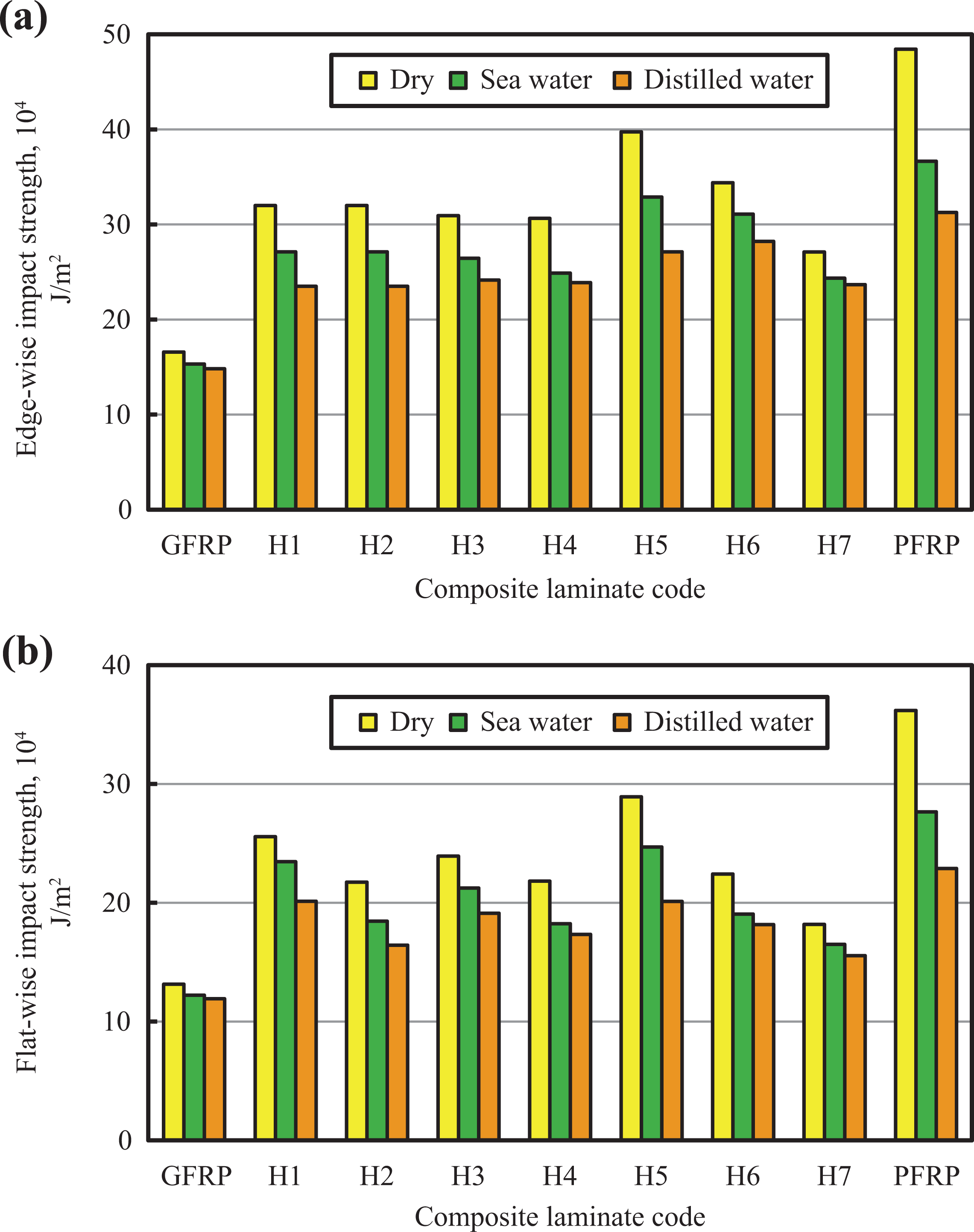
Impact strength of G–P fibers–reinforced epoxy composite specimens under dry and wet conditions.
Dry specimens
The edge-wise and flat-wise impact strength of the PFRP composite is about 2.92 and 2.75 times those of the GFRP one. This is due to the greater elongation of P-fiber at break compared to G-fiber. Elongation at break and impact strength are directly correlated. The high elongation at break of P-fiber increases the elongation at break of the fabricated composites, leading to higher impact strength. This result agrees with that reported by Alomayri et al. 31 It was also noted that G–P hybrid laminates exhibit better edge-wise and flat-wise impact strengths than those of GFRP due to the addition of high elongation P-fiber which improves the impact strength of fabricated hybrids. This result agrees with that obtained by Rahmanian et al. 32
For intraply hybrid composites, the plies stacking sequence has nearly no effect on edge-wise impact strength values, while it has a valuable effect on flat-wise ones. Flat-wise impact strength of H1 is about 1.18 times that of H2 composite with the opposite arrangement. This means that the flatwise impact strength of hybrid composites is controlled by the impacted layer. When P-fiber layerwas at the impacted face as in H1, the composite exhibits higher impact strength. This happens by the fact that the flexible layer at the impacted surface experiences larger deformation. This result agrees with Park and Jang 33 and Rahmanian et al. 32 For the studied intraply hybrid composites, both edge-wise and flat-wise impact strengths of the composites increase asP/G fiber ratio increases.
Wet specimens
It is clear from Figure 5 that the impact strength is adversely affected by water absorption. The decrease in impact strength after water immersion can be related to the weak fiber–matrix interface, which results in a reduction in the impact strength and dimensional stability. This result agrees with that reported by Alomayri et al. 31 As reported by Popineau et al., 34 water molecules entering the network of matrix accelerate matrix cracking which leads to a decrease in impact strength. In the early time of the immersion test, water molecules diffuse into the spaces between polymer chains and occupy the positions between the chains.
The edge-wise impact strength values of GFRP specimens immersed in distilled water and seawater equal 0.89 and 0.92 times that of dry specimens. The edge-wise impact strength values of PFRP specimens immersed in distilled water and seawater equal 0.65 and 0.76 times that of dry specimens. The edge wise impact strength values of inter-intraply and intraply hybrid specimens immersed in distilled water and seawater equal 0.86–0.87 and 0.83–0.9 times that of dry specimens, while the flat-wise impact strength values of GFRP specimens immersed in distilled water and seawater equal 0.91 and 0.93 times that of dry specimens. The flat-wise impact strength values of PFRP specimens immersed in distilled water and seawater equal 0.63 and 0.76 times that of dry specimens. The impact strength values of inter-intraply and intraply hybrid specimens immersed in distilled water and seawater equal 0.70–0.86 and 0.84–0.92 times that of dry specimens.
The decrease in impact strength of wet specimens compared to dry ones is originated from the interfacial degradation caused by water diffusion along the interface between the fibers and matrix. The presence of such amount of water at the interface weakens the interfacial strength which in turn accelerates the failure process. Espert et al. 7 attributed the decrease in the mechanical properties of polymer composites to the effect of the water molecules, which change the structure and properties of the fibers, matrix, and the interface between them. Once the moisture penetrates inside the composite fibers tend to swell. The matrix structure can also be affected by the water uptake by processes such as chain reorientation and shrinkage. Water absorption and their resulting effects contribute to the loss of compatibilization between fibers and matrix, which results in debonding and weakening of the interface adhesion. Water absorption speeds up the evolution of damages inside composites and causes some novel damages. During water immersion test, many properties of the composites are altered because of the changes in the matrix, fiber, and interface. The effects of water absorption on the impact strength of composites are mainly about the matrix plasticization and the interface debonding. The former is usually the reason for the decrease in the composites' strength.
Scanning electron microscopy
The fracture surface morphology of wet and dry G–P fibers–reinforced epoxy composite specimens is presented in Figure 6, where fiber-fracture and matrix failureare highlighted with circles and arrows. Figure 6(a) to (c) shows severe matrix cracking and degradation of the interfacial adhesion between the fibers and the matrix in wet composites characterized by the appearance of gap between fiber and matrix. Water penetration into the composite causes the breaking down of fiber bundles as shown in Figure 6(a). One can observe extensive fiber pullout with no evidence or traces of matrix adhering to the fiber which are an indication of poor fiber–matrix adhesion as shown in Figure 6(d). In contrast, prior to exposure to water, SEM micrographs show almost no fiber pullout, undamaged fiber bundles, and small pieces of epoxy attached to the fiber surface. These results agree with those obtained by Alam et al. 35
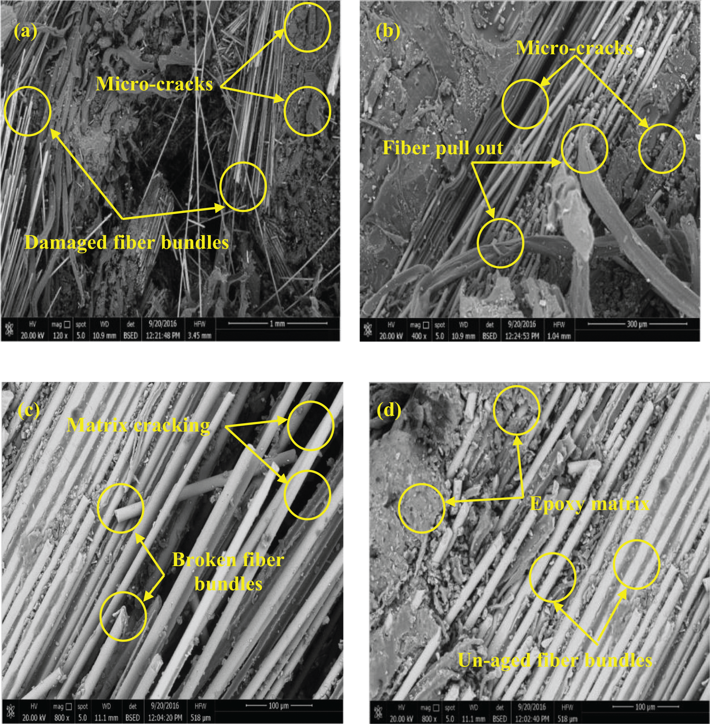
SEM micrographs showing (a) separation of fiber bundles from the matrix, (b) matrix micro-cracks, (c) broken fiber, and (d) epoxy attached to the fiber bundles. SEM: scanning electron microscopy.
Conclusion
G–P fiber–reinforced epoxy composite laminates with different plies stacking sequence, hybrid configuration (intraply or inter-intraply), and P/G fiber ratio have been fabricated using the hand layup process. Specimens were immersed in distilled water and seawater at room temperature, until reaching their water content saturation point. The effect of water absorption on the edge-wise and flat-wise impact strengths of the tested composites has been evaluated. The addition of P-fiber layers into G-fiber-reinforced composites significantly increases the edge-wise and flat-wise impact strengths. The plies stacking sequence has almost no effect on edge-wise impact strength values, while it has a noticeable effect on flatwise ones. The water absorption of the fabricated composites was found to increase with increasing P/G fiber ratio. Distilled water uptake is slightly higher than seawater uptake for all studied composites. Immersing the specimens in distilled water or seawater causes a noticeable reduction in edge-wise and flat-wise impact strengths. SEM micrograph of fractured composites show damage in fiber–matrix interface and damage of G and P-fibers. The water absorption percentage and impact performance can be effectively controlled by changing the hybrid configuration, plies stacking sequence, and P/G fiber ratio.
Footnotes
Declaration of Conflicting Interests
The author(s) declared no potential conflicts of interest with respect to the research, authorship, and/or publication of this article.
Funding
The author(s) received no financial support for the research, authorship, and/or publication of this article.