
Abstract
As a laminate is essentially bonded together from laminae by the matrix, any delamination of it must be initiated from a matrix failure. This article predicts the initiation of a laminate delamination through analyzing the matrix failure. A three-dimensional finite element approach is used to calculate the stress field of an angle-plied laminate under a uniaxial tension. The stresses in each lamina of the laminate are averaged with respect to the lamina thickness to eliminate a weak singularity near a free edge. Homogenized stresses in the matrix are then obtained through bridging model, which are further converted into true values by virtue of stress concentration factors of the matrix in the composite. Influence of any interface crack between the fiber and the matrix on the true stresses has been taken into account. A criterion for detecting the delamination initiation is proposed, which only involves the true stresses and the original strength data of the matrix. To assess the efficiency, comparisons between the predictions and available experiment data are made for a number of angle-plied laminates. Reasonable correlation has been found.
Keywords
Introduction
Delamination is one of the most often occurred failure phenomena in a laminated composite structure. 1 It will degrade the stiffness of the laminate and may induce an earlier ultimate failure. Delamination generally results from the interlaminar stresses or interlaminar stress increments at a free edge, which are very localized and exhibit steep gradients. 2 Near the free edge of the laminate subjected to a uniaxial load, the stress state has to be three-dimensional (3-D) in order to satisfy boundary conditions. The plane stress assumption used in the classical laminate theory is no longer valid. To determine the interlaminar stresses at the free edge, a variety of methods have been developed. Among, a 3-D finite element (FE) approach is most common. 3,4
Regarding a delamination initiation, a criterion involving an average of the interfacial stresses over a characteristic length from the edge is often used because the value of interfacial stresses is weakly singular at the free edges. 4 –6 But, there is not yet a standard to determine such a length and relevant strength data. Kim and Soni 7 took the characteristic length as one-lamina ply thickness and the interlaminar strength to be equal to the transverse strength of the lamina. Their work was followed by some other researchers. 8,9 Sun and Zhou 10 chose six different characteristic lengths to compare their predictions with experiments and concluded that the length of two ply thicknesses was appropriate. Brewer and Lagace 11 deemed that the characteristic length was independent of a ply thickness and should be extracted from experiments. Lorriot et al. 12 proposed a one-parameter assessment procedure, in which the characteristic length and the interlaminar strength were obtained from one kind of laminate and then used for the others with the same materials. Unfortunately, a conclusion that a characteristic length is independent of ply angle, ply thickness, and external load has not been sufficiently confirmed. 12
There are also energy-based approaches to estimate a delamination initiation load, in which an interfacial strain energy release rate and the size of an effective flaw are needed 1,13 in general. Martin et al. 14 proposed a twofold strength and toughness criterion combining a stress condition and an energy equation. A delamination would occur when the strength and the energy conditions were met simultaneously. This criterion was accepted by another author. 15 Diaz and Caron 16 used a model called M4-5N to evaluate the interfacial stresses in a laminate. The approximated interfacial stresses from this model are finite even at the edges, whereas 3-D FE calculations cannot be. A delamination onset criterion involving the maximum value of the interfacial stresses was considered. In addition, they displayed that the interfacial plastic sliding value at the free edge, which was the relative displacement between θ layer and −θ layer at the interface for angle-ply [±θn] s laminates, was almost the same when the delamination happened. So a delamination criterion involving the measured critical sliding value 17,18 was adopted.
Cohesive zone model, which requires the stiffness, strength, and fracture energy release rate of the interface, can predict both the initiation and propagation of a delamination without an initial pre-crack. Turon et al. 19 presented a closed-form expression for the stiffness of a cohesive FE and thought that delamination onset occurred when a point on the interface was not able to carry any traction. Uguen et al. 20 analyzed separately the influence of three parameters on the onset of delamination and compared the predicted results through a linear and an exponential softening law with experimental results of some angle-plied laminates. The maximum difference in the predicted and measured delamination initiation loads was 27.3%. Mohammadi and Majd 21 used a solid-like interface element, in which the thickness was usually considered about one-hundredth of the total thickness of the laminate, to simulate the initiation and propagation of a delamination. They thought that the delamination onset happened when the element shear stress reached the interfacial strength for angle-plied laminates. However, as mentioned by these authors, 19 –21 it is not suitable to simulate a large structure using cohesive elements because very fine meshes are needed to assure a reasonable number of elements in the cohesive zone.
Most of the existing methods for a delamination initiation are phenomenological, which require a lot of experimental data of the laminates. As plies are bonded together by the matrix to form a laminate, any delamination of the laminate must be initiated from a matrix failure and thus controlled by the stresses of the matrix. Fenske and Vizzini 22 thought that delamination was characterized as the failure of the interplay resin-rich layer, and a delamination criterion using both the in-plane and interlaminar stresses in resin-rich layer was developed. Lin 23 investigated experimentally two kinds of composite laminates with different matrix properties and the results indicated that increasing matrix strength and ductility increased the critical load for delamination onset. Kwon and Craugh 24 analyzed delamination zone size of a double-edge-notched laminate through a micro/macro mechanical approach, which used an FE method in macro-level and a 3-D unit cell model to determine fiber and matrix stresses in micro-level. A quadratic delamination criterion 11 was applied to the micro-stresses of the matrix. However, the critical strength parameters of the matrix in the criterion were not obtained from experiments on the matrix material. Instead, they assumed the shear strength of the matrix to be one half of its tensile counterpart, whereas the choice for the latter was not found in the study by Kwon and Craugh. 24
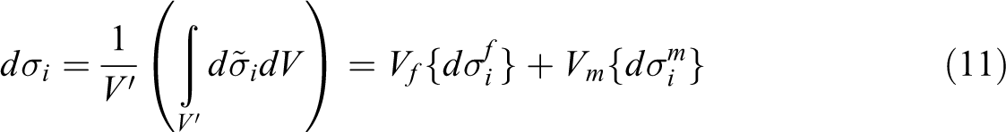
In this study, a new and simple approach combining 3-D FE method (FEM) and analytical bridging micromechanics model 25 has been made to predict an initiation of delamination in terms of the stresses of the matrix. The FEM is necessary to obtain the stress distribution of a laminated structure especially at free edges, and bridging model is then used to determine the internal stresses in the constituent fiber and matrix of each element. The most important feature is in that the internal stresses in the matrix thus obtained are homogenized quantities. They are converted into true values before failure detection for the matrix is made against the original strength data of the matrix. 26 The conversion is accomplished by multiplying the homogenized counterparts with stress concentration factors (SCFs) of the matrix in the composite. 26 Various SCFs including the transverse tensile one after the interface crack between the fiber and matrix are calculated according to the literature. 26 –28 Then, a stress-based delamination failure criterion only involving the true stresses and the original strengths of the matrix has been applied to predict a delamination initiation load. The biggest merit of this work is in that only the original property data of the fiber and matrix measured independently are required, in addition to a transverse tensile strength of the lamina made of the same constituents which is used to determine when an interface crack will occur in the laminate. A number of T800/914 carbon–epoxy angle-ply laminates [±θn] s with lamination angles (10° ≤ θ ≤ 30°) are analyzed. The predicted delamination initiation loads correlate reasonably the experimental results reported in the study by Lorriot et al. 12
FE simulation
Discretization on laminate
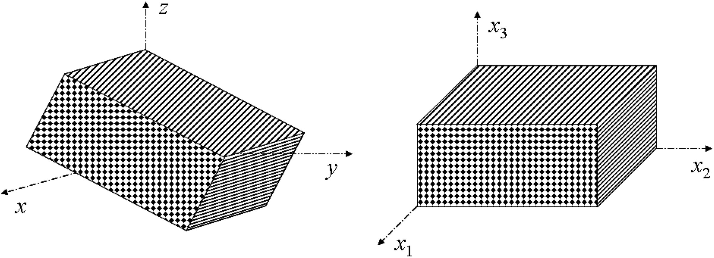
Consider a symmetrically angle-plied laminate [±θn] s with different lamination angle under a uniform uniaxial tension. The laminate occupies the following geometry: length L = 40 mm, width b = 15 mm, and thickness h = 4n × t, where t = 0.125 mm being the thickness of each ply. Global coordinates x, y, and z correspond to the length, width, and the thickness directions, respectively, as shown in Figure 1. A 3-D FE modeling through ABAQUS is developed to perform a stress analysis for the laminate. Because of symmetry, the analysis is carried out only for the upper half of the laminate. A uniform tension of σ is applied along the x-direction on the surface at x = L. The boundary conditions are specified as follows

where u, v, and w are the displacements of the laminate along the x-, y-, and z-directions, respectively. An eight-node solid element (C3D8R) is chosen for the analysis. To achieve a convergent solution, three rectangular mesh sizes in the x–y plane are used. All are gradually refined to the free edges, as shown in Figure 2. The coarse mesh (Figure 2(a)) is consisted of 36 elements in the y-direction and 77 elements in the x-direction, the medium mesh (Figure 2(b)) is of 136 elements in the y-direction and 107 elements in the x-direction, and the fine mesh (Figure 2(c)) is of 246 elements in the y-direction and 210 elements in the x-direction. Each element is considered as a unidirectional (UD) lamina in its local coordinate system. The solutions from the latter two mesh sizes are essentially the same if the mesh size along the thickness direction keeps unchanged. We will come back to this again with some more detail in a subsequent section. Hence, the medium mesh in the x–y plane is used throughout in this work unless for a comparison study.
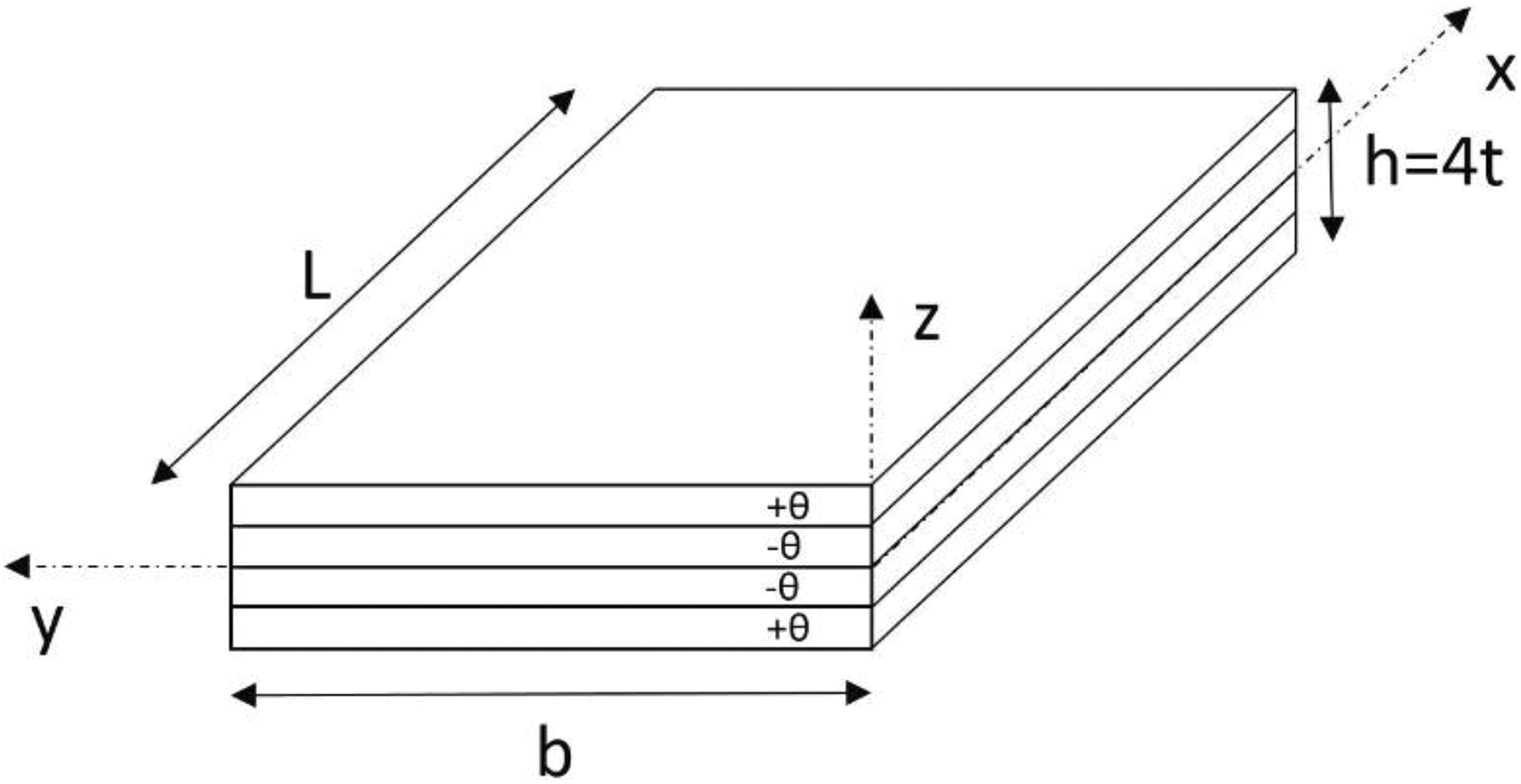
Geometry of a [±θ] s laminate.
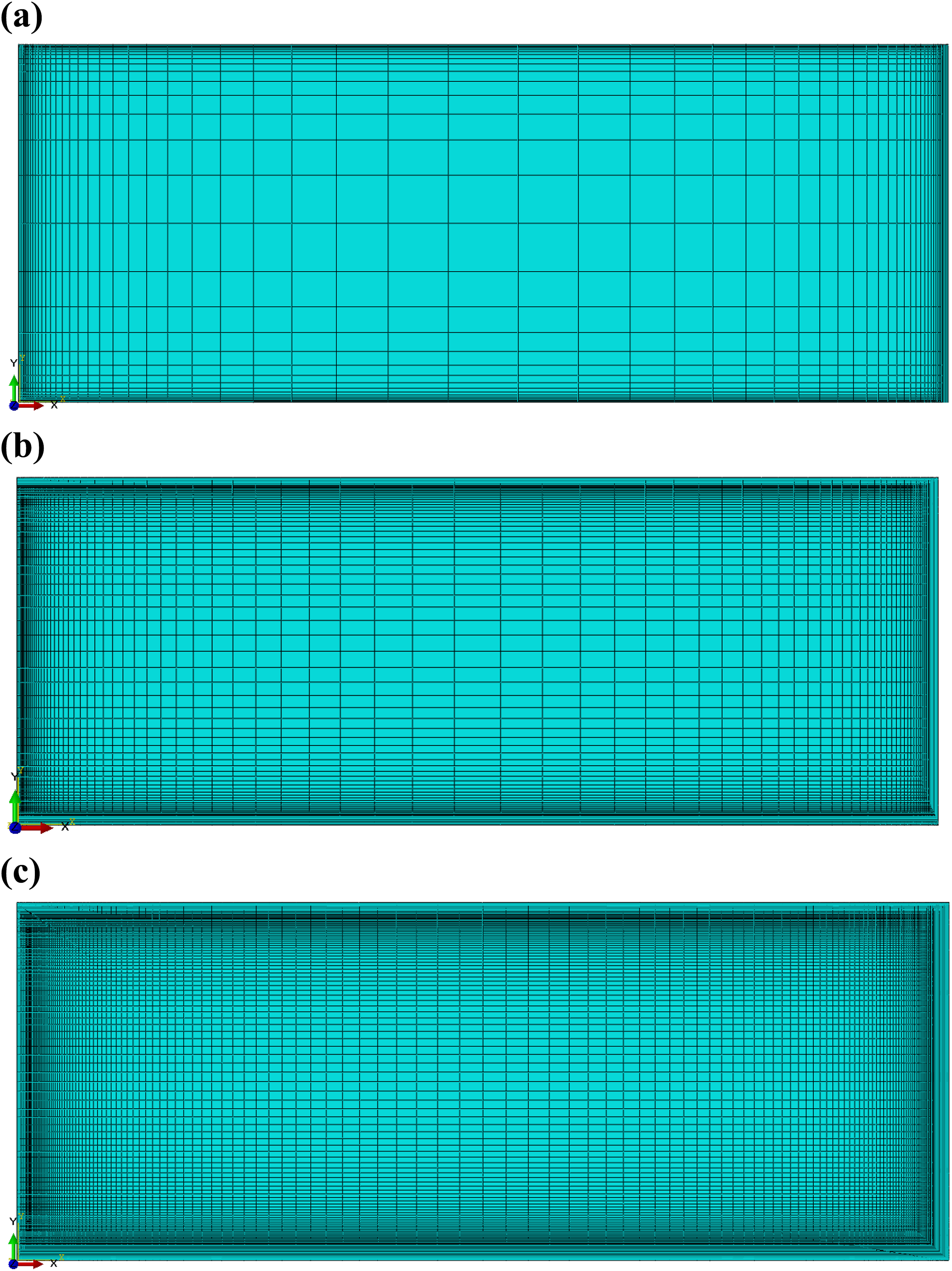
Meshing a laminate in x–y plane. (a) Coarse mesh. (b) Medium mesh. (c) Fine mesh.
Material properties
The material system used is T800 carbon fiber and 914 epoxy matrix. 12 No constituent properties were provided in the study by Lorriot et al. 12 Instead, the mechanical properties of the UD composite from this system were given, as presented in Table 1. They are matchable to those made from IM7 fiber and 914-C matrix provided in Huang and Xin, 29 which are also shown in Table 1. Thus, the original elastic and strength parameters of the T800 fiber and 914 matrix are assigned as those of the IM7 fiber and 914-C matrix. They are summarized in Table 2. 29 It is noted that a fiber volume fraction of Vf = 0.55 was adjusted in such a way that the predicted elastic properties of the UD composite by bridging model from Table 2 were close to those shown in Table 1.
Mechanical properties of UD composites. 12
UD: unidirectional.
Original mechanical properties of IM7 fiber and 914-C matrix. 29
Determination of internal stresses
We choose to use bridging micromechanics model 25 to determine the internal stresses in the fiber and matrix owing to two reasons. First, it results in simple and explicit formulae for all of the internal stresses. This is considered to be the most appealing feature of bridging model. 30 Second, it is among the most accurate micromechanics theories. 31
Homogenized stresses
First, the stress increments at any point of a ply, {dσ} G = {dσxx, dσyy, dσzz, dσyz, dσxz, dσxy} T , which are calculated by the FE method in the global coordinate system, are transformed into those in the lamina local one, {dσ} = {dσ11, dσ22, dσ33, dσ23, dσ13, dσ12} T , by the following equations (Figure 3)

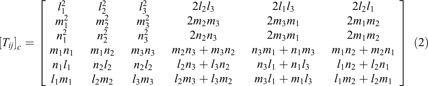
where li = cos(x, xi), mi = cos(y, xi), and ni = cos(z, xi). Suppose that the fiber and matrix are linearly elastic until rupture. The internal stress increments in the fiber and matrix of each ply are determined in terms of bridging model as 25


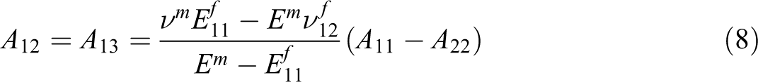
where non-zero bridging matrix elements are given below.
Stress conversion from global coordinates to local coordinates.
True stresses
The internal stresses calculated by bridging model, or any other micromechanics model, are homogenized quantities. This is because any stress increment of a solid is defined on averaging with respect to an element through the following equation
When the volume of the element, V′, becomes infinitesimal, the resulting stress increment, represented by
The homogenized internal stresses of the constituents cannot be used to compare with their ultimate values to determine a failure in general. Otherwise, an untrue result is seen. Consider, for example, E-Glass/LY556 UD composite subjected to a transverse tension σ22. Its strength is controlled by a matrix failure. Using the constituent data given in the study by Soden et al.,
32
the non-zero matrix stresses are found from bridging model as
A similar conclusion can be reached no matter which other micromechanics model is used or which other composite is considered. This means that the homogenized internal stresses must be converted into true values before an effective specifically failure property of the composite is evaluated in terms of the original constituent property data. The stresses in the fiber are uniform, 33 and its homogenized and true stresses are the same. The true stresses of the matrix are obtained by multiplying the homogenized counterparts with SCFs of the matrix in the composite. This is because a plate with a hole generates a stress concentration under an in-plane tension. When the hole is filled with a fiber of different properties, the stress concentration occurs as well.
The most important task is to correctly define an SCF. The traditional definition for an SCF, that is, the maximum point-wise stress divided by the overall applied one, is no longer applicable herein, because, otherwise, the resulting SCF would be infinite if there is a crack on the fiber and matrix interface. A point-wise stress of the matrix at the crack tip is singular. The traditional definition is something like zero-dimensional (i.e. point-wise) over two-dimensional (since the overall applied stress is actually a surface-averaged quantity) stresses. By similarity, the new definition can only be a line-averaged (one-dimensional) stress divided by a volume-averaged (3-D) quantity.
Explicit formulae for various SCFs 26 –28 of the matrix are summarized in Appendix 1. How to obtain the true stresses of the matrix at the current load step from its homogenized counterparts is also given there.
Criterion for delamination initiation
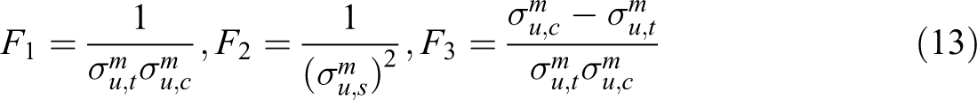
As mentioned previously, any delamination must be initiated from a matrix failure, which can be detected using Tsai–Wu criterion since an isotropic matrix belongs to a subset of the assemblage from anisotropic composites. Following the study by Kim and Soni, 7 a contribution of in-plane stresses to the delamination failure can be ignored. Thus, the initiation of a delamination takes place if the following condition is fulfilled

where l is a load step, and
Results and discussion
Simulation results of FEM
The stiffness matrix of each UD lamina in its local coordinate system is defined as 25

Hence, the stiffness of a 3-D FE is defined accordingly. In equation (14),
Choose [±10] s laminate as an example. When the number of elements in the thickness direction is set to 2, the stress distributions for σxz along the width direction calculated by the three rectangular meshes are shown in Figure 4. It is seen that the results from the medium and fine meshes are essentially the same, meaning that the medium mesh in the x–y plane is dense enough to obtain an accurate stress solution.

Interlaminar stress σxz at z = t in T800/914 [±10] s laminate versus y.
The stress distributions of σxz along the width direction obtained by using 2–10 elements in the thickness of a ply are plotted in Figure 5. From this figure, we can see that the interlaminar stress is restricted within a small region whose width is approximately equal to the laminate thickness h. A weak stress singularity exists at the free edge due to material property and geometry discontinuities. In other words, there is a remarkable but unconvergent magnitude of the interlaminar stresses in this region. Many similar reports can be found in the literature 4 –6 as well.
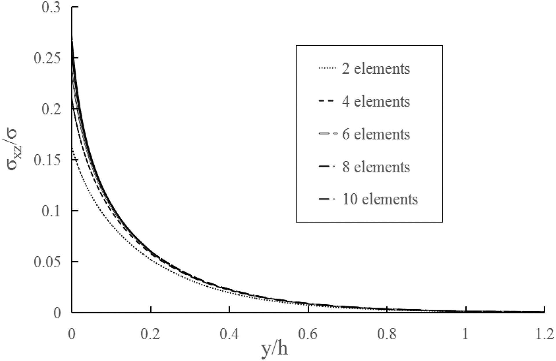
Interlaminar stress σxz at z = t in T800/914 [±10] s laminate versus y for different number of elements along thickness of each layer.
Figure 6 shows the stress distributions of the interlaminar stress σxz along the thickness direction versus the elements used through a ply thickness. In the middle surface of [±10] s laminate, the value of the interlaminar stress σxz is equal to zero and reaches the maximum on the (+10/−10) interface. There also exists a great stress gradient in the thickness direction near the (+10/−10) interface. Again, the weak singularity is found.
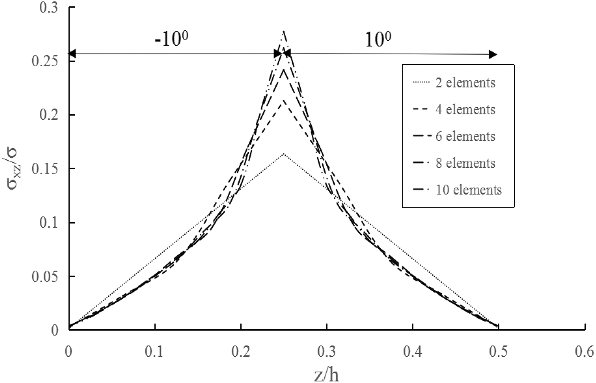
Interlaminar stress σxz at y = b in T800/914 [±10] s laminate versus z for different number of elements through thickness of each layer.
This kind of singularity can be eliminated by taking an average on the stresses of each ply with respect to its thickness t. Figure 7 shows the averaged stress distributions versus element number used along the ply thickness. From Figure 7, it can be concluded that the averaged interlaminar stress is constant as long as the element number in the thickness of each ply is equal to or greater than 2. So a stable and well-defined quantity at the free edge can be obtained, which are used as input on the right-hand side of equations (9) and (10), after the coordinate transformation, to determine the internal stress increments in the fiber and matrix of the ply.
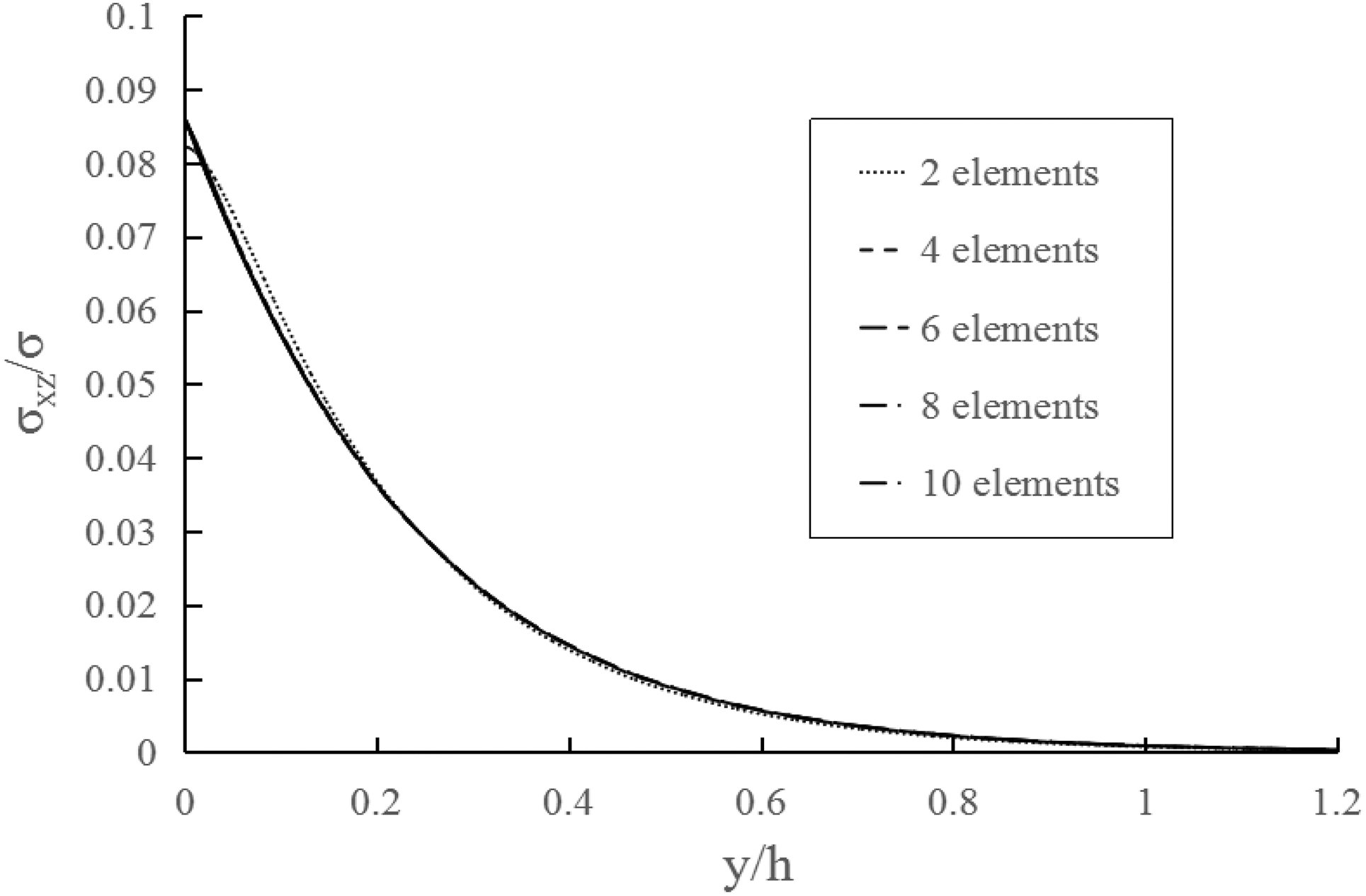
Average interlaminar stress σxz in −10 ply versus y for different numbers of elements through thickness of each layer.
Prediction of delamination initiation
By making use of the FE approach, bridging model, the corresponding SCFs, and the delamination failure criterion, critical loads that lead to delamination of the T800/914 angle-plied laminates [±θn] s are predicted. Herein, all of the SCFs necessary for the prediction are calculated from the constituent data given in Table 2. They are presented in Table 3.
SCFs of 914-C matrix in the IM7/914-C composite.
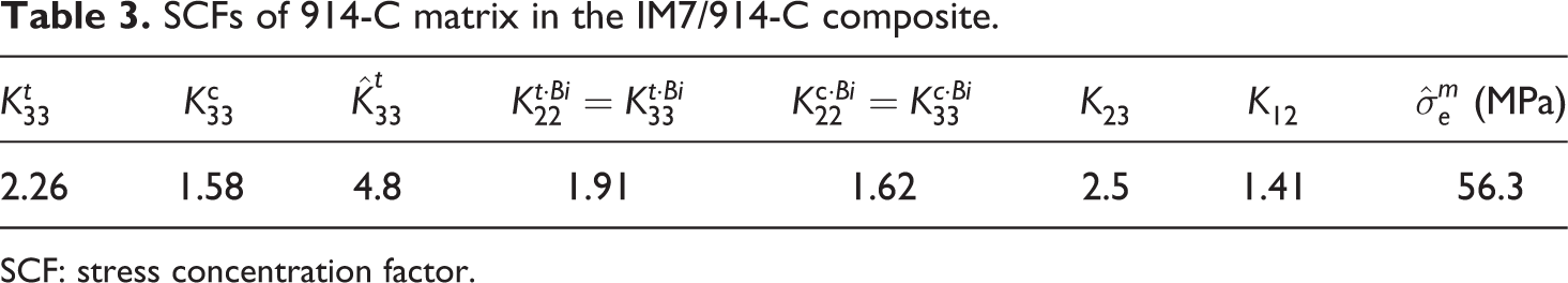
SCF: stress concentration factor.
Three laminates, [±10 n ] s , [±20 n ] s , and [±30 n ] s , with n = 1 to 5, are considered. For each laminate, the predicted and the measured strengths taken from Lorriot et al. 12 are comparably shown in Table 4. The table indicates that most of the correlation errors between the predictions and the experiments are less than 30% except for the [±10] s laminate for which a relative large error of 31.7% has been seen. The averaged error is 17.9%, which is a reasonable value.
Predicted and measured delamination initiation strengths for IM7/914-C angle-plied laminates.
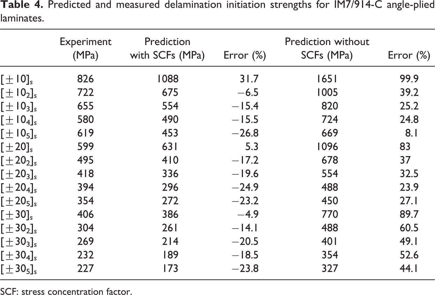
SCF: stress concentration factor.
Several reasons may be attributed to the relative large error between the predicted and measured delamination initiation strengths. First, the measured delamination initiation strengths may not be very accurate. As a delamination is initiated from a free edge at its very small neighborhood, it is not easy to measure the initiation load. No measurement standard is yet available. Second, measurements for the input constituent data will generate deviation errors. The constituent data necessary for a failure, for example, delamination initiation, prediction are more than double of those required for a stiffness prediction. A prediction of a micromechanics theory for the elastic properties of a composite generally can achieve an overall correlation error with measured data of not less than 10%. 34 It is natural that the micromechanical prediction for the failures of the composite would result in an overall such error of around 20%. This is because the more the number of input data used the more the accumulated error should be involved.
As aforementioned, the most critical issue is to convert the homogenized stresses of the matrix into true quantities by virtue of the SCFs of the matrix in the composite, if a failure prediction of the composite is to be made micromechanically. To further illustrate, the prediction without any of the SCFs incorporated, by simply setting all of the SCFs to be one, has also been made. Such a prediction is traditional. Namely, the homogenized stresses of the fiber and matrix obtained through a micromechanics are compared with their attainable ultimate values (strength data) to determine a constituent and hence a composite failure. The predicted results are presented in Table 4. Obviously, the predictions without SCFs differ from the experiments much more significantly. Although the minimal error was 8.1% for the [±105]
Comparison with cohesive model
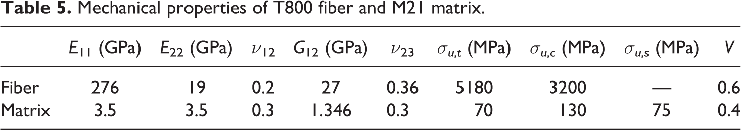
Ugen et al. 20 measured and predicted the delamination strengths of T800/M21 angle-ply laminates in terms of cohesive elements. In order to compare the matrix damage as stratification with the cohesive model, we also investigated this material, T800/M21, using our method. The constituent properties of carbon T800 and epoxy M21 are provided in Table 5. The carbon–fiber properties are the same as those in Table 2. Only elastic properties of the M21 matrix were provided in the study by Tserpes and Chanteli, 35 whereas Ugen et al. used a shear strength σu,s of the matrix in their modeling. 20 These property parameters are used in this work. The other two strengths of the matrix have not been found directly from the literature. Instead, we choose to use the corresponding strengths of the 5260 epoxy matrix provided in the study by Huang and Zhou, 25 because the elastic properties of the M21 are comparable to those of the 5260. All of the SCFs calculated upon the data of Table 5 are presented in Table 6.
Mechanical properties of T800 fiber and M21 matrix.
SCFs of the M21 matrix in T800/M21 composite.
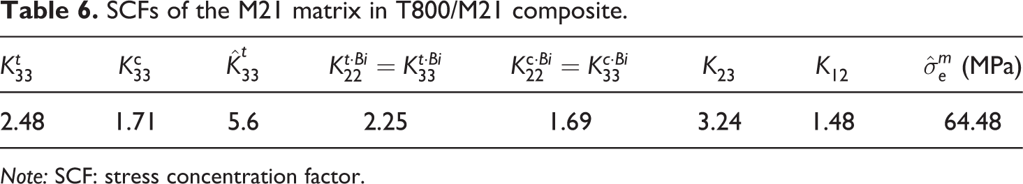
Note: SCF: stress concentration factor.
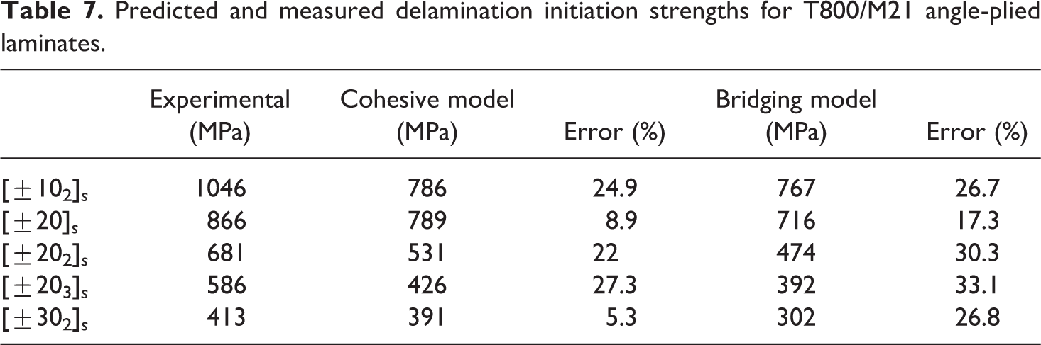
Following the same steps for the T800/914 laminates, the predicted delamination initiation strengths in terms of bridging model for the T800/M21 laminates are deduced and shown in Table 7. The predictions of Ugen et al. with the cohesive model 20 and the experimental data are also displayed in Table 7. It is seen that the errors by our method for this example are comparatively larger than those with the cohesive elements. The averaged error by the cohesive model is 17.7%, whereas that by this method is 26.84%. Considering that our method requires the minimum number of input data especially without any experiment on the laminates under investigation, and in the light of big deviations in the measured delamination strengths, the prediction by our method is reasonable especially when used as a first estimation purpose.
Predicted and measured delamination initiation strengths for T800/M21 angle-plied laminates.
Improvements in the prediction accuracy of this method can be made through several efforts. First, the input data in the delamination initiation prediction were taken from other documents, which may introduce errors in the original properties of the fiber and matrix. Tests on the constituent especially matrix original properties to establish a well-documented material datasheets are necessary. Second, a linear elasticity up to failure assumption was made for both the fiber and matrix. In reality, a matrix material can undergo a plastic deformation, which can influence the calculation of the homogenized internal stresses in the fiber and matrix. Similarly, incorporation of the thermal residual stresses in the fiber and matrix may benefit a prediction. Third, a more efficient failure criterion for detecting a delamination initiation deserves development. The present work simply used a criterion adapted from Tsai–Wu theory, which may not be very pertinent for all cases. Finally, a rule of “more-pay-more-gain” is always true in general. If some additional experimental data on the laminates are available and are effectively used with our method, a higher prediction accuracy can be expected.
Conclusions
In this article, the authors present a micromechanical method to analyze an initiation of delamination at a free edge in an angle-plied laminate. The stress field at any point of the laminate is calculated by an FE approach. The interlaminar stresses in the vicinity of its free edges exhibit a stress singularity that can be solved by taking an average for them in each lamina of the laminate with respect to the lamina thickness. The averaged stresses are then used for bridging model to determine the homogenized internal stresses in the fiber and matrix. Whereas the fiber stresses have no effect on the delamination initiation, the matrix homogenized stresses must be converted into true values before an interlaminar failure detection can be made in terms of the original strengths of the matrix. The most significant feature of this work is in that essentially no other experimental data on the composite are required, except for its transverse tensile strength which is necessary to estimate the interface crack between the fiber and matrix in the composite. The correlation between predicted and measured delamination initiation loads for a number of angle-plied laminates is reasonable.