
Abstract
In this article, the nonlocal buckling behavior of biaxially loaded graphene sheet with piezoelectric layers based on an orthotropic intelligent laminated nanoplate model is studied. The nonlocal elasticity theory is used in the buckling analysis to show the size scale effects on the critical buckling loads. The electric potential in piezoelectric layers satisfies Maxwell’s equation for either open- or closed-circuit boundary conditions. Based on the third-order shear and normal deformation theory, the nonlinear equilibrium equations are obtained. In order to obtain the linear nonlocal stability equations, the adjacent equilibrium criterion is used. The linear nonlocal governing stability equations are solved analytically, assuming simply supported boundary condition along all edges. To validate the results, the critical buckling loads are compared with those of molecular dynamics simulations. Finally, the effects of different parameters on the critical buckling loads are studied in detail. The results show that by increasing the nonlocal parameter, the critical buckling load decreases. The piezoelectric effect increases the critical buckling load for both open- and closed-circuit boundary conditions. For open-circuit boundary condition, the variation in the critical buckling load is due to the stiffness and piezoelectric effects, but for closed circuit, it is due to the stiffness effect only. Also, the critical buckling load for open circuit is bigger than that of closed one.
Keywords
Introduction
Nanoplates are one of the most important structures that are widely used in different fields of engineering. Atomic scale structures made of carbon atoms are extensively used as nanoresonators, sensors, actuators, atomistic dust detectors, capacitors, solar cells, liquid crystal displays, and transistors. The structure of graphene consists of a two-dimensional single atomic layer of carbon atoms arranged in a honeycomb lattice that has an ability to implement in a number of various branches because of its premier properties such as electrical, thermal, chemical, mechanical, and optical. It is the thinnest known material and the strongest ever measured in the world. Graphene sustains current densities as six times higher than copper and shows record thermal conductivity and stiffness. It is impermeable to gases and has the conflicting qualities as brittleness and ductility. 1 Because of such wonderful mechanical and electrical properties, it is extremely proposed to be used in nanodevices. 2
Various theories have been employed to study the nanoplates. Although analyzing by three-dimensional theory of elasticity is a basic and accurate method, it accompanies with some complexities and difficulties. To reduce the complexities of three-dimensional elasticity theory, other theories such as classic and shear theories have been presented which their accuracies depend on the number of terms that have been accounted in the displacement field expansion. Both the classic and shear theories are far from the accurate answers because they omit the effects of normal and shear strains simultaneously. To resolve this problem and to achieve more accuracy, Batra and Vidoli 3 have introduced the shear and normal deformation theory, where the effects of both shear and normal deformations are considered.
In nanostructures, the interatomic large forces widely affect the mechanical behavior of the structure. The classical elasticity theory does not account the small-scale effect and is generally unsuitable for the mechanical analysis of the nanoplate. Generally, controlling the experiments in nanoscale are difficult and also the molecular dynamic simulations for nanostructures with large numbers of atoms or molecules are extremely computationally prohibitive. Hence, there are some modified continuum-based theories considering the small-scale effect such as modified couple stress theory, 4 strain gradient elasticity theory, 5 nonlocal elasticity theory, 6 and so on. Among the modified continuum-based theories, the most extensively reported theory, which has been applied for the mechanical analysis of nanoplates with considering small-scale effect, is the nonlocal elasticity theory that has been introduced by Eringen. The nonlocal theory of Eringen is based on this hypothesis that the stress tensor at a point depends not only on the strain tensor at that point but also on the strain tensor of other points in the domain. 6
Many researchers have solved the buckling problems of nanoplates based on the nonlocal elasticity theory. Radic et al. 7 analyzed the buckling of double-orthotropic nanoplates based on nonlocal elasticity theory. They supposed that two nanoplates were bonded by an internal elastic medium and surrounded by external elastic foundation and governing equations were derived for a nanoplate with simply supported edges. Pradhan and Phadikar 8 solved the buckling analysis of multilayered graphene sheets embedded in a polymer elastic medium based on the nonlocal elasticity theory. In their work, graphene sheets have been supposed as an orthotropic nanoplate. They solved the governing equations using Navier’s method for simply supported boundary condition. Malekzadeh et al. 9 studied the small-scale effect on the thermal buckling of orthotropic arbitrary straight-sided quadrilateral nanoplates using the differential quadrature method. The surrounding elastic matrix has been modeled as the two-parameter elastic foundation. They derived the governing equations utilizing the classical and nonlocal elasticity theories.
Today, piezoelectric materials have very common applications in various fields of industries. Their electromechanical coupling specifications induce electrical polarization under mechanical loads and also cause mechanical deformations under electrical fields. These properties make them proper for a diversity of electromechanical system utilized for data collection, cooling systems, and sensor networks. In 2002, a shear and normal deformation theory for piezoelectric plates was introduced. 3 In their paper, the displacement field and electric potential were expanded as series in the direction of thickness using Legendre polynomials. In addition, results were obtained for bending of a cantilever thick plate loaded on the top and bottom surfaces by uniformly distributed tractions. Wang and Yang 10 have reviewed the progression of higher order theories for the dynamic analysis of piezoelectric plates and classified the theories according to the transverse distribution of the displacement components and electric potential. Tiersten 11 has studied the fundamentals of static and dynamic analysis for a single-layered piezoelectric plate. He analyzed the static and dynamic deformations of piezoelectric plate.
Graphene sheets play an important role in modern technology, so a good realization of the mechanical behaviors of nanostructures is vital for designing and performance assessment of their mechanical systems. On the other hand, besides the superior mechanical and electrical properties of graphene, a combination of graphene sheet with piezoelectric layers leads to the production of nanostructures with controllable specifications and with specific applications in industry.
To the best of authors’ knowledge, there is not any analytical study on the buckling of smart nanoplates based on the shear and normal deformation and nonlocal elasticity theories. In this article, applying the shear and normal deformable nanoplate theory and Eringen’s nonlocal model, the buckling of simply supported graphene sheet with a combination of piezoelectric layers is studied analytically. To verify the analysis, results are compared with the simulated results based on the molecular dynamics in related papers.
Problem formulation
The electromechanical coupling properties in piezoelectric materials make them a suitable candidate in varied electromechanical machines. The key privileges of these kinds of intelligent materials are high precision and sensibility and low weight. For a piezoelectric layer, polarized in the thickness direction, the constitutive relations and electric displacement vector (interaction between mechanical and electrical fields) can be demonstrated as the following relations 12
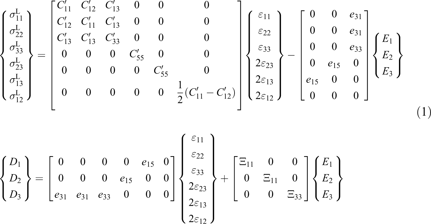
Where the superscript “L” refers to the local situation, so
A schematic of the considered smart nanoplate, which is constructed from graphene and piezoelectric layers, is illustrated in Figure 1. Suppose
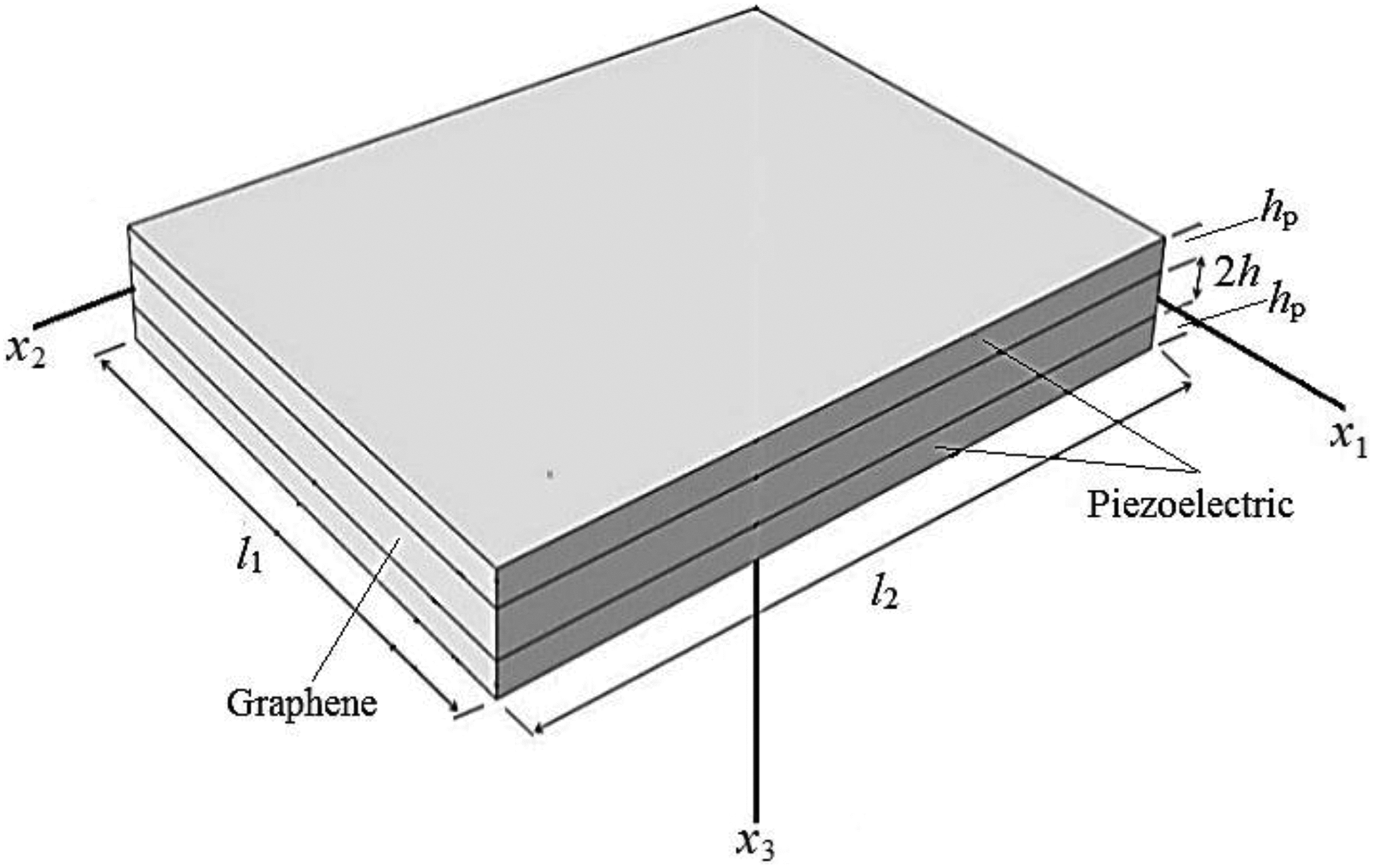
The geometry and coordinate system of smart nanoplate.
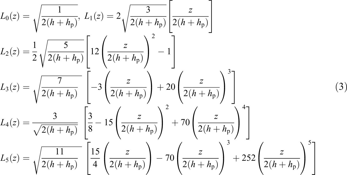
In the shear and normal deformation theory, in order to decrease the algebraic operations and expand the displacement field components in the thickness direction, the Legendre polynomials as the basis functions are utilized. Let La be orthonormal Legendre polynomials, its necessary condition is defined as follows 3
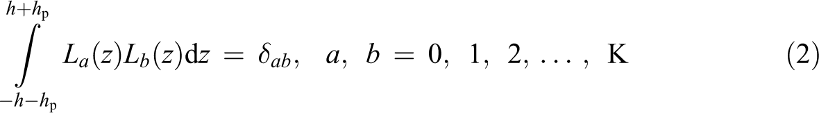
where δ ab is the Kronecker delta and a, b are dummy indices. It can be seen that the terms corresponding to the product of Legendre polynomials with dissimilar indices will disappear, in equilibrium equations. For example, the first six orthonormal Legendre polynomials are expressed by the following relations
The basic functions

where

where ui denotes the components of the total displacement field, vα indicates the in-plane components of displacement, and w the lateral deflection of an arbitrary point in the smart nanoplate. Repeated indices, such as a, indicate dummy indices.
Noting that the derivative of

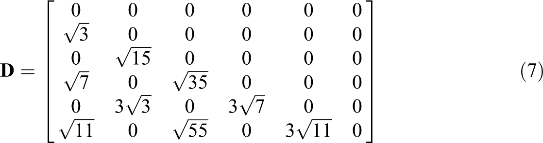
where for K = 5, the matrix of coefficients
Substituting relations in equation (5) into the nonlinear form of strain–displacement relations, the strain components in the shear and normal deformation theory are obtained as follows

where subscripts (,) shows differentiation with respect to the corresponding coordinate.
The interatomic forces effect on a typical atom, depend on the relative variations of distances between this atom and its neighboring ones. Thus, the interatomic forces on each atom depends not only on its own displacements but also on the displacements of atoms in its neighborhood. Furthermore, the second dependency is significantly effective and known as the small-scale effect. The small-scale effect may be considered by the continuum-based nonlocal elasticity theory supposing that the stress at a point depends on the strains at either that point or all points on the effective neighborhood area. According to nonlocal elasticity theory, 6 the following differential constitutive relation can be expressed

where ∇2 is the Laplacian operator, e0l shows the small-scale effect, l is an internal characteristic length, for example, lattice parameter or carbon–carbon bond length, e0 is a material constant, and the superscript L refers to the local parameters.
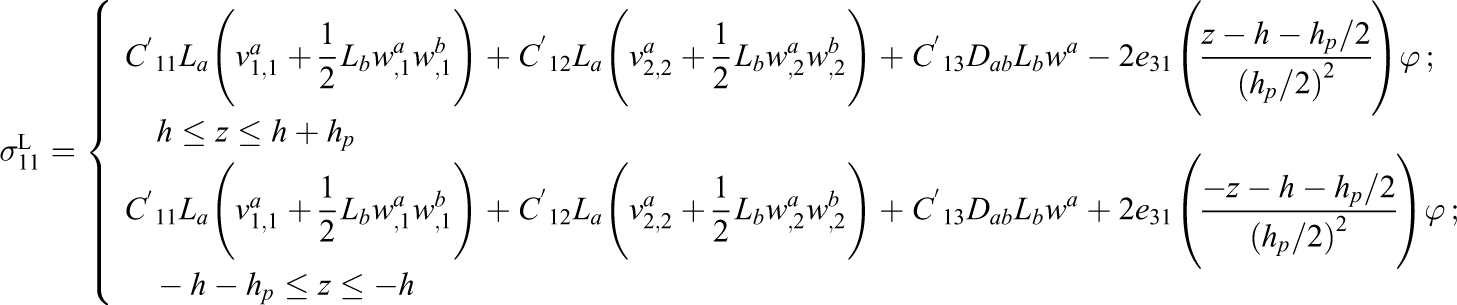
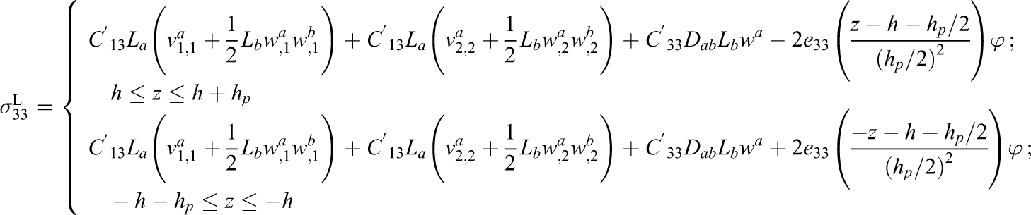
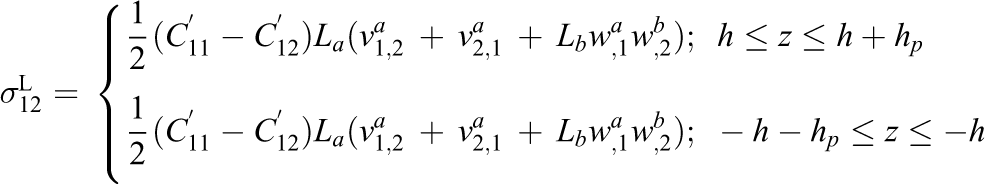
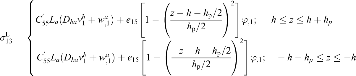
Using the nonlinear relation of strain–displacement (equation (8)) and engineering constants, the components of local stress tensor,
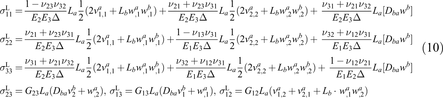
where
Electric problem
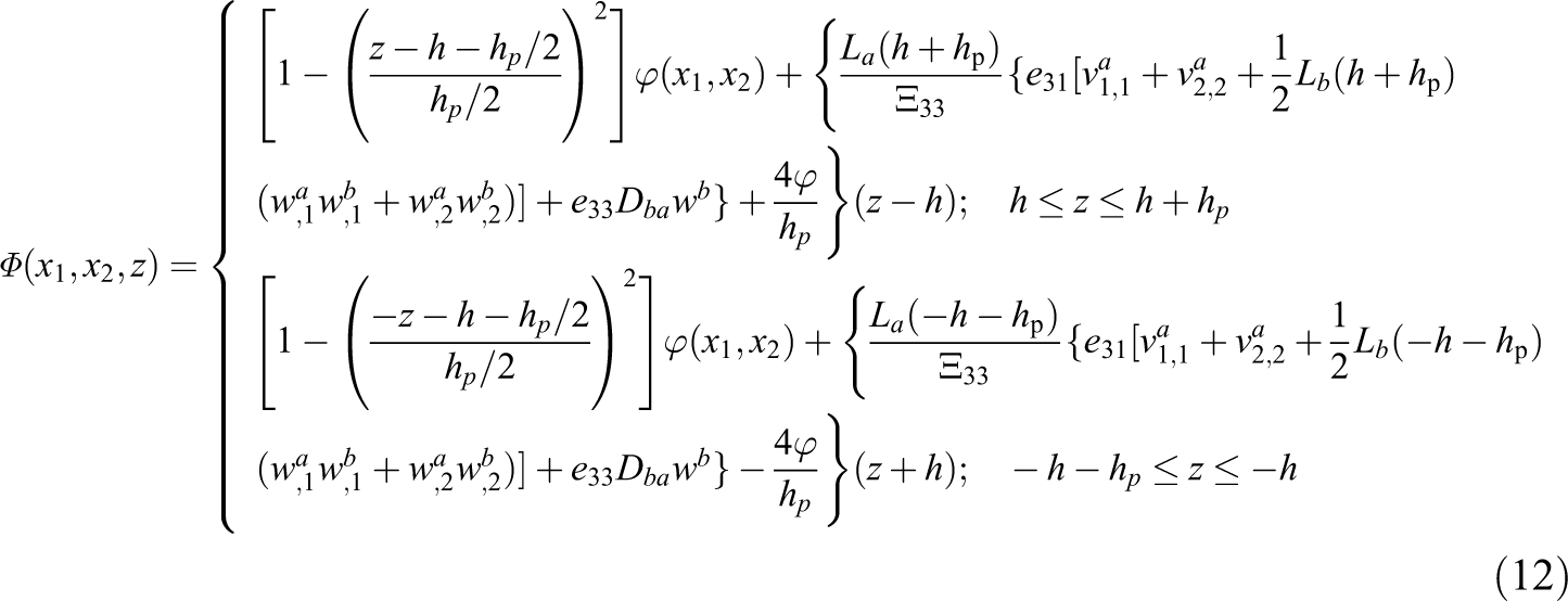
The electric potential is supposed to vary in the thickness direction as a quadratic function, which has been verified by finite element method. If the inner surface of each piezoelectric layer is held at zero voltage and the outer one is electrically insulated (open-circuit condition), the following electrical boundary conditions on surfaces of the piezoelectric layers can be considered 13

For open-circuit condition, it can be assumed the following quadratic variation of electric potential to satisfy the boundary conditions (equation (11))
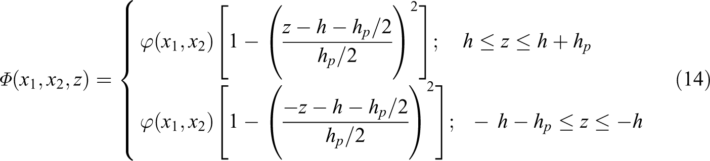
However, when both upper and lower surfaces of the piezoelectric layers are held at zero voltage (closed-circuit condition), the electrical boundary conditions on major surfaces of the piezoelectric layers are assumed as following relations 13

That is, the outermost surfaces of the piezoelectric layers and the interfaces between the layers are held at zero potential. For closed-circuit condition, the quadratic variation of electric potential which satisfies the boundary conditions (equation (13)) is assumed as
Accordingly, the electric field is related to the electric potential by

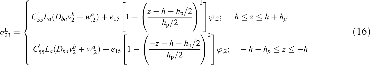
Upon substituting the strain–displacement relations (equation (8)) and electric field (equation (15)) in equation (1), the components of stress tensor and electric displacement vector in terms of displacement components for closed-circuit piezoelectric layers, are derived as

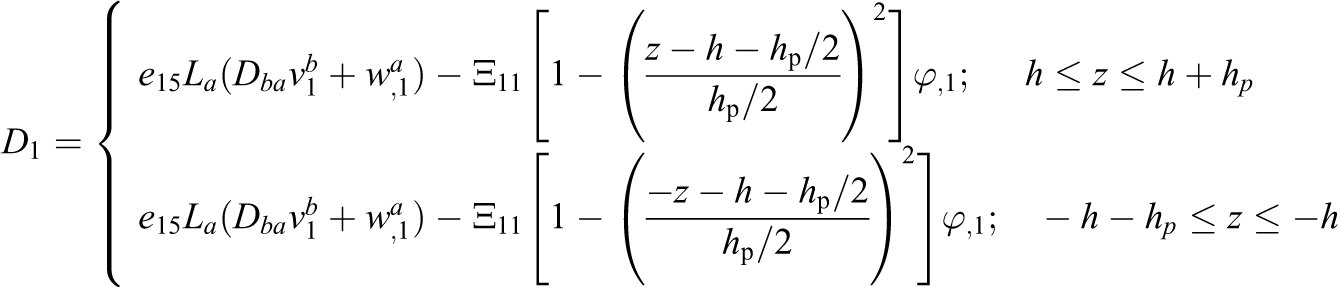
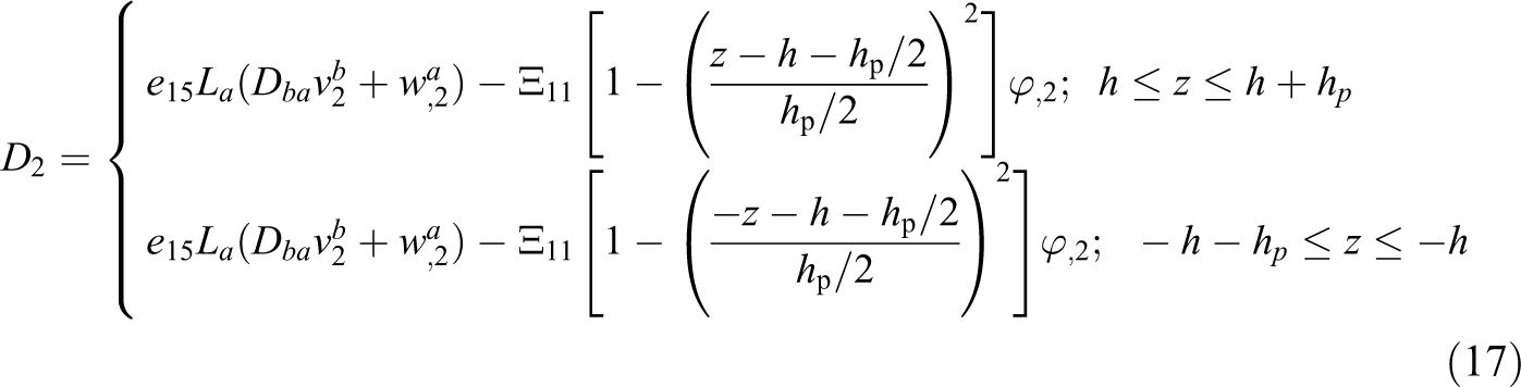
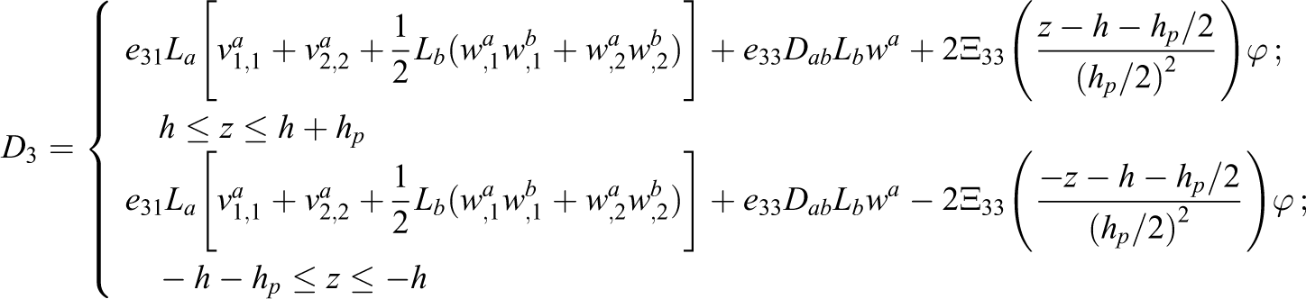
Also, the components of electric displacement vector for closed-circuit boundary condition are obtained as
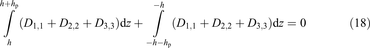
The electric potential in the piezoelectric layers is supposed such that satisfies the Maxwell equation. Therefore, all electrical variables must satisfy the following integral form of this equation 13,14
Linear nonlocal governing stability equations
Using the principle of minimum total potential energy, 15 the nonlinear equilibrium equations of a smart nanoplate based on the shear and normal deformation theory are obtained as

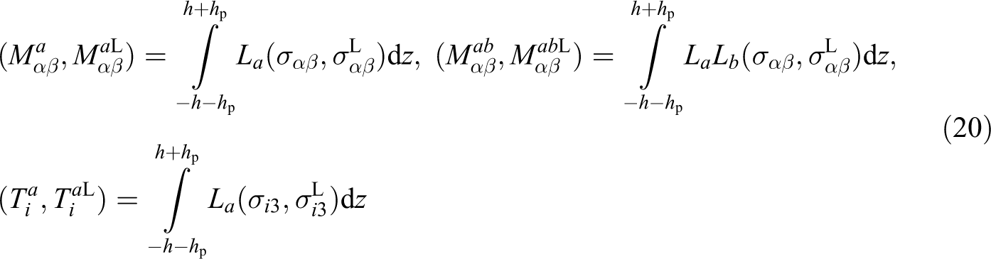
Equations (18) and (19) are nonlinear equilibrium equations of intelligent nanoplate subjected to in-plane loading based on the shear and normal deformation theory, where
Since the strain components are nonlinear, the resultants of moment are nonlinear, too.
While nanoplates are subjected to in-plane loads, they are deformed. Since in-plane displacements of the nanoplate are free, it buckles freely and collapses. The buckling load is increased to the critical buckling load that leads to instability of the nanoplates. Since deformations in buckling are large, nonlinear equations govern the buckling. Nevertheless, it was shown that for pre-buckling analysis, linear equations are accurate, but for the post-buckling, nonlinear forms must be used. 16
In order to study the buckling behavior of the smart nanoplate and obtain the linear stability equations, the adjacent equilibrium criterion is used. In other words, after using the adjacent equilibrium criterion, the stability equations are linear. According to this criterion, a neighboring state of equilibrium is considered as an increment in the displacement field. In other words, based on this criterion, a nanoplate is stable if the displacement components vary incrementally from the equilibrium situation. Thus, two states are considered, equilibrium state (with nonlinear form of governing equations) and neighboring state (with linear form of governing equations).
16
Suppose that the equilibrium state of an intelligent nanoplate under mechanical loads is defined in terms of displacement components

Substituting relations in equation (21) into equation (20), the expressions for the moment resultants related to the equilibrium and neighboring states are obtained. Equivalently, the resultants of moment can be derived as

where the terms with superscript 0 are corresponding to the equilibrium state and consist of nonlinear parts of the displacement components. Also, the terms with superscript 1 are linear parts of the moment resultant increments corresponding to the neighboring state.
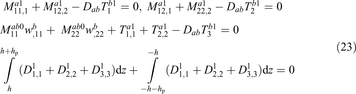
The linear stability equations may be obtained by substituting relations in equations (21) and (22) into equations (18) and (19). Upon substitution, the terms in the resulting equations with superscript 0 satisfy the Maxwell relation and equilibrium condition and therefore are omitted from these equations. Also, the nonlinear terms with superscript 1 are ignored because they are small compared to the linear terms. The remaining terms form the linear stability equations of smart nanoplate as follows
The constant parameters
The nonlocal moment resultants
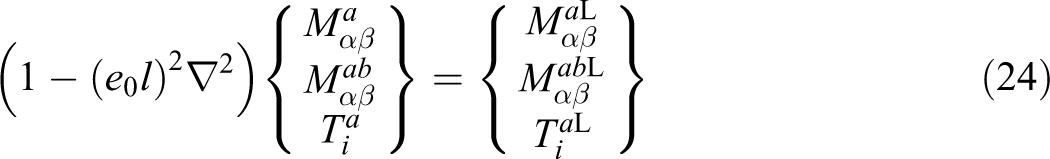
Substituting the constitutive relations in equation (24) into the stability equation (23) yields
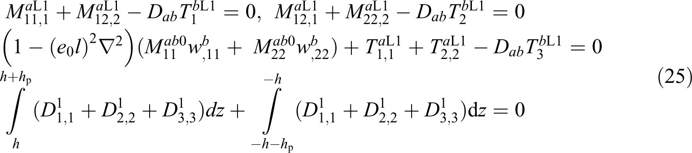
Equation (25) is nonlocal linear stability equation in terms of moment resultants. By substituting the relations in equation (20) into equation (25), one can write
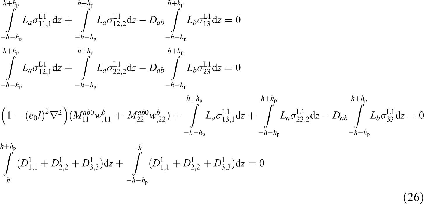
The relations in equation (26) indicate the linear nonlocal stability equations of the orthotropic smart nanoplate subjected to in-plane loading based on nonlocal elasticity and shear and normal deformation theories.
In order to obtain the linear nonlocal governing stability equations of orthotropic smart nanoplate for closed-circuit condition, the equivalent neighboring form of constitutive equations of orthotropic graphene sheet (equation (10)), piezoelectric layers (equation (16)), and the electric displacement vector (equation (17)) are substituted into equation (26). It is necessary to mention that in deriving these equations, the linear parts of displacement components are only included in both constitutive equations and the electric displacement vector. The eigenvalue problem defined by these equations should be solved for the critical buckling load. Based on the boundary conditions of the smart nanoplate, one can employ different analytical approaches to solve them.
Buckling analysis
Consider a rectangular orthotropic intelligent nanoplate in the Cartesian coordinates, with the length l1 and width l2, which is subjected to uniformly distributed in-plane compressive loads in two directions. Therefore, the pre-buckling resultant forces may be derived using the equilibrium conditions as

where q1 and q2 are two independent load per unit length parameters. equation (27) may be simplified to a single parameter equation by defining a nondimensional load parameter ratio
For a simply supported rectangular smart nanoplate, the boundary conditions along the edges can be expressed as

Actually, the in-plane displacements along each axis are allowed for edges perpendicular to that axis and not for the parallel ones. For electrical boundary conditions, with regard to the Navier’s method and the linear nonlocal governing stability equations, the edges

The boundary conditions of smart nanoplate in equations (28) and (29) are identically satisfied using the so-called Navier’s method. This method supposes the modal displacement components and the electric potential to be as
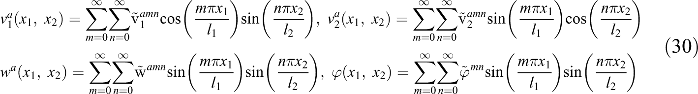
where the coefficients
Substituting relations in equation (30) into the linear nonlocal governing stability equations in the previous section will alter the system of partial differential equations into a system of algebraic equations that have been described in Appendix 1. It is obvious that the algebraic equations (1A) to (1D) represent an eigenvalue problem and their eigenvalues are the buckling loads. Hence, the critical buckling load is the smallest of them.
Numerical results and discussion
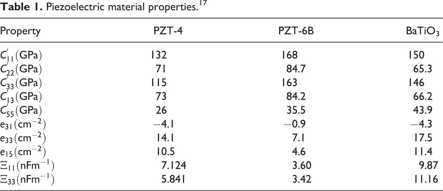
In order to validate the accuracy of obtained results by this procedure, a comparison has been carried out with molecular dynamics simulations in previously published articles. The piezoelectric material properties have been given in Table 1. 17
Piezoelectric material properties. 17
It is noticeable that the magnitude of the mechanical properties, effective thickness, and small-scale parameter must be specified for graphene sheet. Scarpa et al. 18 have proved that the material properties at nanoscales were size-dependent. Huang et al., 19 assumed that Young’s modulus E = 2.99 TPa, Poisson’s ratio ν = 0.397, and sheet thickness was 0.0811 nm for the graphene sheets. Some researchers suggested that the graphene thickness and Young’s modulus were 0.34 nm and 1 TPa, respectively. 20 The existence of a wide range of mechanical properties for graphene is due to the uncertainty in its thickness dimension.
An efficient and successful application of the nonlocal elasticity models for graphene sheets is an important subject and depends on if an accurate value of the nonlocal parameter is available. A very limited number of investigations have been performed on finding the correct value of the small-scale parameter. Yet, there is no general agreement on the value of nonlocal elasticity parameter. Hu et al. 21 compared nonlocal shell models for dispersion of propagating waves in carbon nanotubes with results from molecular dynamics simulations. They proposed e0 equal to 0.6 and 0.2 for transverse and torsional waves, respectively. Some investigators evaluated e0l by comparing the observed results from molecular dynamics simulation with those obtained from the nonlocal theory. 22 Others presumed the nonlocal parameter less than 2 nm and based on its different values, have analyzed the graphene sheets. 4,23 –27
Due to the large dispersion of small-scale parameter values in the previous studies, it seems more researches are required for achieving a nonlocal parameter correct value. By now, no experiments have been performed to determine the value of small-scale parameter for graphene sheets. In this article, small-scale parameter is determined through matching the critical buckling loads obtained by nonlocal elasticity theory with those calculated from molecular dynamics simulation. Hence e0l is set as calibrated variable for the nonlocal elasticity theory.
The zigzag and armchair structures have been shown in Figure 2 and the mechanical and geometrical properties for these two graphene sheets have been listed in Table 2 according to Shen et al. 22
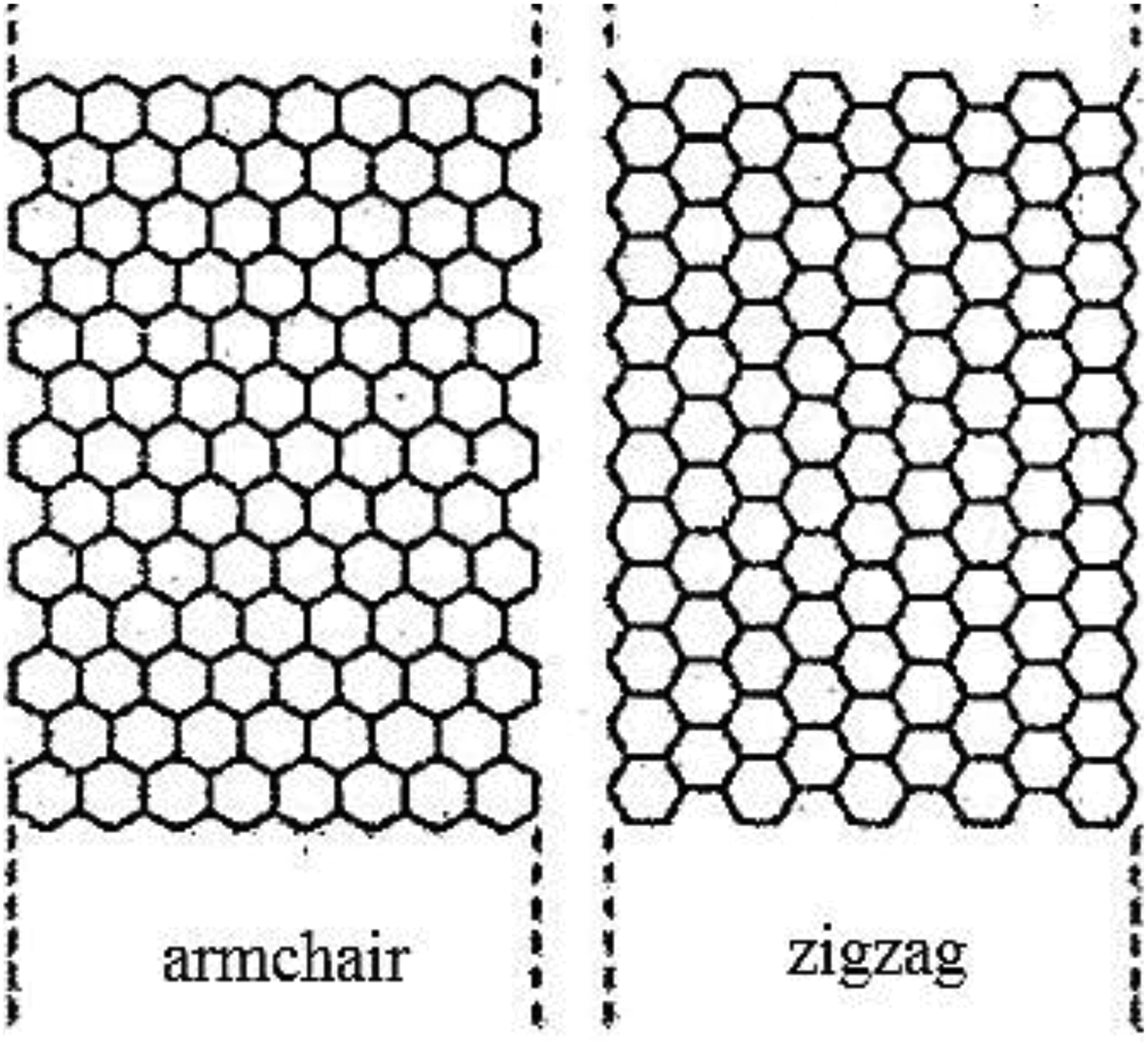
The zigzag and armchair graphene sheets.
Properties of graphene sheets. 22
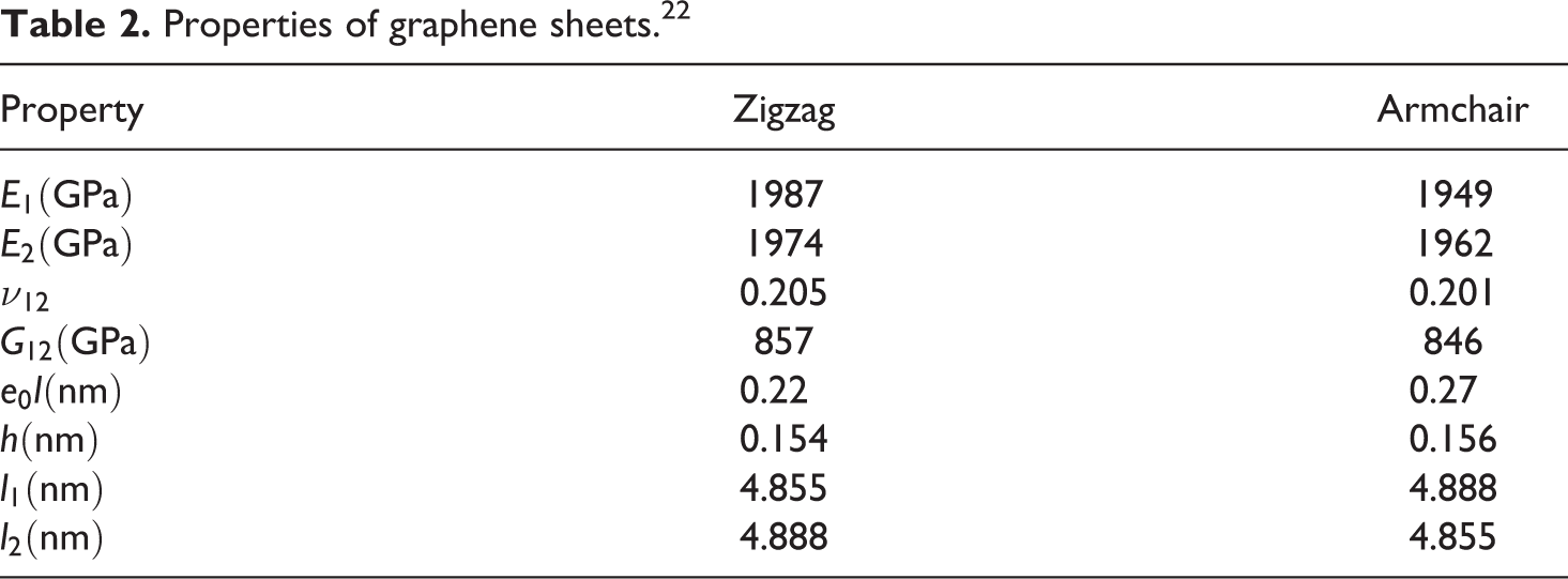
The exact properties in Table 2 have been acquired by comparison between natural frequencies of graphene sheets based on the molecular dynamics simulation and the nonlocal elasticity theory. The observed difference between the values of nonlocal parameter for zigzag and armchair nanoplates is due to the chirality-dependent anisotropy of graphene sheet structures.
Although Shen et al. 22 demonstrated that the mechanical properties in zigzag and armchair directions are different, this is negligible. Due to this very small difference, the same critical buckling load for both zigzag and armchair nanoplates will be obtained. The critical buckling loads for these two structures have been tabulated in Table 3.
The critical buckling loads of zigzag and armchair graphene sheets.
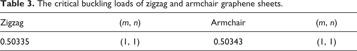
The obtained results listed in Table 3 show that there is an excellent agreement between the critical loads for two structures of graphene sheets. In addition, for the reason of very small difference in properties, in simply supported boundary conditions nanoplates under biaxial compression with aspect ratio close to one, it is expected that the buckling will occur in first mode, too.
In order to validate the accuracy of the present formulations and results, the critical buckling loads based on third-order shear and normal deformation theory are compared with the known previous works. Table 4 shows the comparison of the critical buckling loads for different dimensions derived by the present analysis with the results obtained based on molecular dynamics by Ansari and Sahmani 27 and Nanorex Inc. 2 8 All comparisons have been done based on molecular dynamics simulator NanoHive. 28 This is a free open-source molecular dynamics simulator which has certain features that can be used to model different loading conditions of nanostructures. For results in this table, the piezoelectric layers have been made of PZT-4 as in Table 1 and the mechanical and physical properties of graphene are as follows

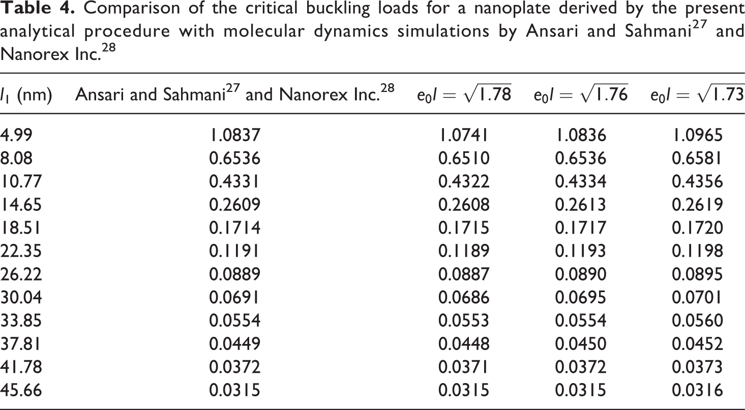
From Table 4, it can be seen that for
After verifying the merit and accuracy of the present solutions, to express the buckling behavior of smart nanoplate, the related results based on third-order shear and normal deformation theory are presented. Unless stated otherwise, the numerical results for buckling of an orthotropic smart nanoplate including an armchair-type graphene sheet and piezoelectric layers made of PZT-4 material (as in Tables 1 and 2) have been derived. In order to compare the results with those of other theories, a nondimensional critical buckling load factor, q cr, has been defined by
where
In Table 5, the nondimensional critical buckling loads of smart nanoplate for aspect ratio near to one, thickness–length ratio
The nondimensional critical buckling loads of smart nanoplate for different thickness ratio and nonlocal parameter with
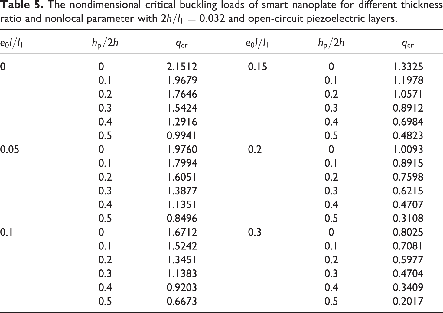
As Table 5 shows it is obviously visible that while increasing the nonlocal parameter, the critical buckling load decreases. In addition, it can be found that increases in both the critical buckling loads and thickness ratio (hp/2h) are in direct relation. According to this table, increases in the thickness of the smart nanoplate and critical buckling load obey this rule, too.
The nondimensional critical buckling loads of a smart nanoplate under biaxial compression for different nonlocal parameter and thickness–side ratio have been listed in Table 6.
The nondimensional critical buckling loads of smart nanoplate for different thickness–side ratio and nonlocal parameter with
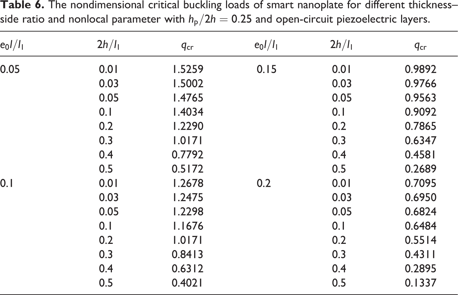
From the results presented in Table 6, it is clear when
To show the significant effects of the buckling phenomena, the results are also plotted in a few figures. In Figure 3, the nondimensional critical buckling load for a smart nanoplate has been plotted versus the thickness ratio. Based on this figure, the critical buckling load decreases as the small-scale parameter increases. Also, it can be seen that bigger critical buckling loads are required to cause buckling in thicker smart nanoplates.
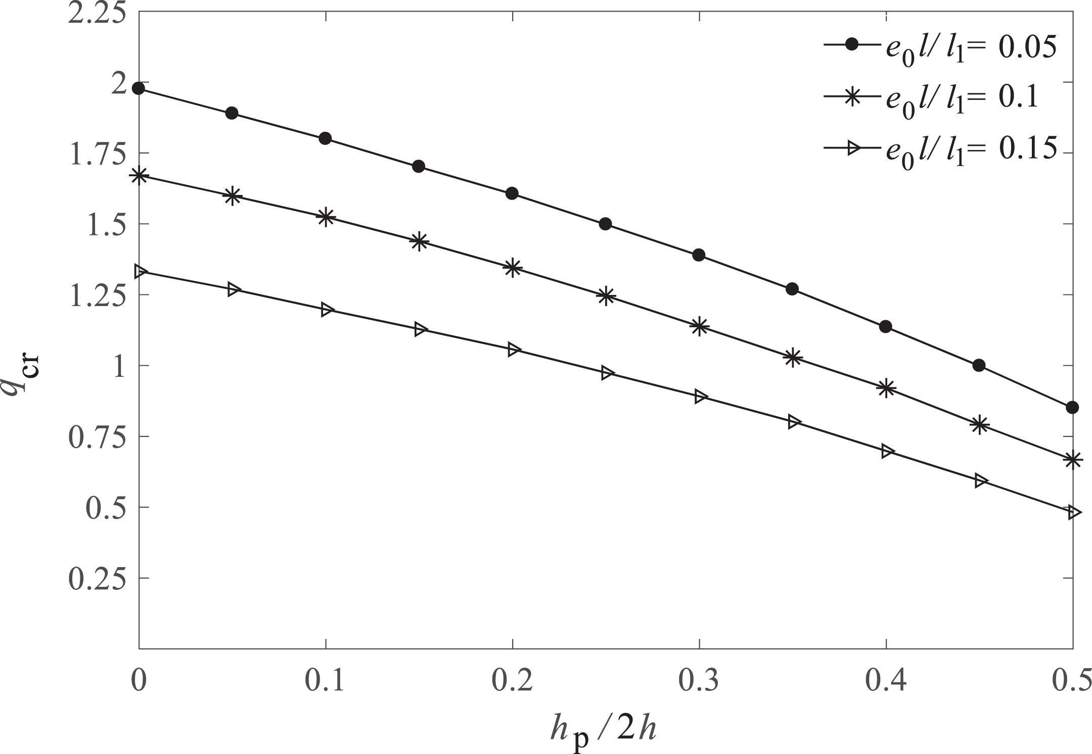
The variation of nondimensional critical buckling load versus the thickness ratio for a graphene sheet coupled with open-circuit piezoelectric layers for different nonlocal parameter (
In Figure 4, the nondimensional critical buckling load versus the thickness–side ratio has been depicted for a smart nanoplate.
The variation of nondimensional critical buckling load versus the thickness–side ratio for a graphene sheet coupled with open-circuit piezoelectric layers for different nonlocal parameter (
In this figure, it can be seen that the critical buckling load generally increases as the thickness–side ratio becomes bigger. In addition, a decrease in the length of the smart nanoplate severely leads to an increase in the critical buckling load.
In Figure 5, the effects of smart nanoplate thickness on the nondimensional critical buckling loads for different materials of piezoelectric layers have been investigated.
The variation of nondimensional critical buckling load versus the thickness ratio for a graphene sheet coupled with open-circuit piezoelectric layers for different piezoelectric materials (
This figure shows the nondimensional critical buckling loads of graphene sheet coupled with open-circuit piezoelectric layers for different thickness ratios. It can be seen that the magnitude of the critical buckling load for PZT-4 is at least and for PZT-6B at most. Also, this figure shows that the results for three different types of the piezoelectric layers material are qualitatively similar to each other but in terms of quantity have different effects on the critical buckling load. Moreover, in this figure, for two piezoelectric materials PZT-6B and BaTiO3, the critical buckling load values are very close to each other.
Figure 6 demonstrates the effect of the piezoelectric layers thickness on the nondimensional critical buckling load of a square smart nanoplate for both open- and closed-circuit boundary conditions. In addition, the mechanical effect of the piezoelectric layers which is known as the stiffness effect,
29
by equating the piezoelectric charge constants matrix
The variation of nondimensional critical buckling load versus the thickness ratio for a smart nanoplate for open- and closed-circuit piezoelectric layers, piezoelectric and stiffness effects (
In Figure 6, it can be seen that for open-circuit piezoelectric layers, the change in the critical buckling load is due to the stiffness and piezoelectric effects, but for closed circuit, the stiffness has only dominant effect and the piezoelectric effect is negligible. For a magnitude of
Conclusions
In the present article, an analytical approach was developed for the buckling analysis of orthotropic smart nanoplate. Based on the third-order shear and normal deformation and nonlocal elasticity theories, the nonlinear equilibrium equations were derived in conjunction with the principle of minimum total potential energy. Then, using the adjacent equilibrium criterion, the linear nonlocal stability equations were obtained. To solve the linear nonlocal governing stability equations, the Navier’s solution was presented for the smart nanoplate with simply supported boundary conditions. Moreover, the success of the present analysis was verified through comparison with available results such as the molecular dynamics simulation. The small-scale parameter was determined through matching the critical buckling loads with those obtained from the molecular dynamics simulation. As comparison shows, for As the small-scale parameter increases, the critical buckling load decreases and the rise of thickness ratio and thickness–length ratio causes the critical buckling load to become greater. The magnitude of critical buckling load for an open-circuit piezoelectric layer is greater than that of a closed circuit, regardless of plate dimensions. Results reveal that the critical buckling loads for piezoelectric materials PZT-4 and PZT-6B have, respectively, the smaller and larger values in a thickness ratio and the difference between magnitudes of the critical buckling loads for PZT-6B and BaTiO3 is negligible. The trends of the three piezoelectric materials, namely BaTiO3, PZT-6B, and PZT-4, are similar, however, they have quantitatively various influences on the critical buckling loads. In the small thickness ratio, the piezoelectric effect on the critical buckling load is insignificant for both open- and closed-circuit piezoelectric layers, while in higher thickness ratio, this effect is negligible only for closed circuit. The electromechanical coupling due to the matrix For the closed-circuit boundary conditions, the critical buckling load depends on the stiffness effect only, but for open circuit, it depends on both stiffness and piezoelectric effects.
Footnotes
Declaration of Conflicting Interests
The author(s) declared no potential conflicts of interest with respect to the research, authorship, and/or publication of this article.
Funding
The author(s) received no financial support for the research, authorship, and/or publication of this article.
Appendix 1
By replacing equation (30) into the linear nonlocal governing stability equations in section “Linear nonlocal governing stability equations,” the system of partial differential equations are converted into a system of algebraic equations as follows
Relations (1A) to (1D) are the nonlocal algebraic equations for the buckling analysis of an orthotropic smart nanoplate with closed-circuit condition based on the nonlocal elasticity and shear and normal deformation theories. For a Kth order theory, referring to free index a, it can be observed that there exists 3(K + 1) + 1 equations. Therefore, for K = 3 (a, b, c, d = 0, 1, 2, 3), a system of 13 algebraic equations require to be solved. The buckling loads of the orthotropic smart nanoplate are obtained by equating the determinant of the coefficients matrix of equations (1A) to (1D) to zero. Thus, the smallest buckling load is known as the critical buckling load.