
Abstract
In this study, a novel carbon helical/coiled yarn was prepared for developing an electromagnetic (EM) absorbing structure in C-band region (4–8 GHz). The carbon helical yarn was fabricated in a direct twisting machine in which a stainless steel (SS) filament was used as the core and carbon yarn was used as the wrapping thread. The woven and plain knit structures were prepared using the carbon helical yarns. Subsequently, composites were prepared by film stacking method by sandwiching a helical yarn fabric between the polypropylene films. The shielding behaviour of fabrics and the composites was tested using the waveguide method. It was observed that 1/1 plain knit fabric having an optimum number of core SS filaments and helical yarn density of 50–150 turns/m showed a higher absorption coefficient of 0.91 than other fabrics. Hence, a particular proportion of helical carbon and SS content in a fabric maximizes its absorption coefficient. In the composite form, the absorption level was reduced and behaved like a metal. In addition, increase in fineness of core SS filaments also decreased the absorption behaviour of fabrics and composites. However, the overall shielding effectiveness of fabric and composite was increased for increasing the wrapping density. Compared to fabric form, composites showed larger reflective and total loss. In addition, three-point flexural strength and impact energy absorption of helical yarn composites were also investigated. The developed fabrics can be used as EM absorbing structures in domestic and military applications, whereas the composite can be used as shielding panels to the replacement of metal shield.
Keywords
Introduction
Most of the shielding materials reflect the unwanted/disturbing electromagnetic (EM) radiation. In an ideal shield, the incident EM waves should be absorbed and not to be reflected back to the radiating source. In certain application areas such as radome, army secret rooms and electronic boards of aircrafts, reflective shielding is not recommended. In such case, radiated signal from the source should be absorbed by the shield. To develop such absorptive shield, many materials such as carbon, Mumetal, and stainless steel (SS) fibres were investigated for shielding behaviour. It is reported in the literature that high-magnetic materials such as SS could exhibit a better EM absorption behaviour. 1 Fundamentally for developing such shield, different conductive fillers such as carbon nanotubes, nickel, and SS were reinforced in the polymeric composites. 2 Nevertheless, the fillers lack in larger aspect ratio, hence the use of continuous conductive fillers such as textile fibres is explored for developing the composite absorber. Paul 3 reported that SS fibre–based shielding material imparts better absorption to EM radiation. Several works have been carried out on SS-based woven and knitted structures for the purpose of EM shielding. 4 However, very limited studies reported the absorption and reflection coefficients of SS-incorporated structures. Similarly, carbon-based shields have been investigated for shielding behaviour. Essentially, carbon fibres attenuate the EM radiation by means of reflection. Cheng et al. 5 and Bedeloglu et al. 6 have reported the shielding effectiveness (SE) of fabric having copper and SS filaments. They observed that the use of copper and SS fibres improved the SE of fabric. In this work, the absorption behaviour of fabric was not reported. To improve the absorption behaviour of hybrid yarn fabrics, structural configuration of yarn should be modified. Several studies have been conducted on modifying the fibre configuration in micro and nano-level for better EM absorption. Fejes and Hernádi 7 stated that helical form of carbon nanotubes is the ideal material for EM wave absorbents, tunable micro-devices, bioactivators, Li-battery electrodes and hydrogen containers. Lau et al. 8 reported that regular coiled nanotubes display excellent mechanical, electrical and magnetic properties due to their peculiar helical morphology. In addition, changes in resistivity, conductance, electromagnetic and electromechanical capabilities of helical carbon materials should be investigated in detail. Shaikjee and Coville 9 reported that coiled carbon fibre improves the electric permittivity and conductivity of the polymer matrix, hence EM shielding effectiveness of composite is enhanced. From the studies of several researchers, it can be observed that coiled carbon structures can provide better EM absorption along with superior mechanical properties. 10 Commonly, absorption of EM wave occurs by means of dielectric loss, conductive and magnetic losses. The carbon microcoils (CMCs) are similar to chiral materials which exhibit different EM interaction phenomena compared to straight carbon fibres. Upon incidence of EM radiation, an electromotive force is developed in the chiral structures according to Faraday’s law. This chiral microcoil acts as a micro-solenoid and forms inductive current from the inductive electromotive force. Later, the induced current gets attenuated due to the resistance of the coiling material. To form inductive current, coiling-chiral morphology of the fibres is more effective than that of straight or powder-like forms. 11
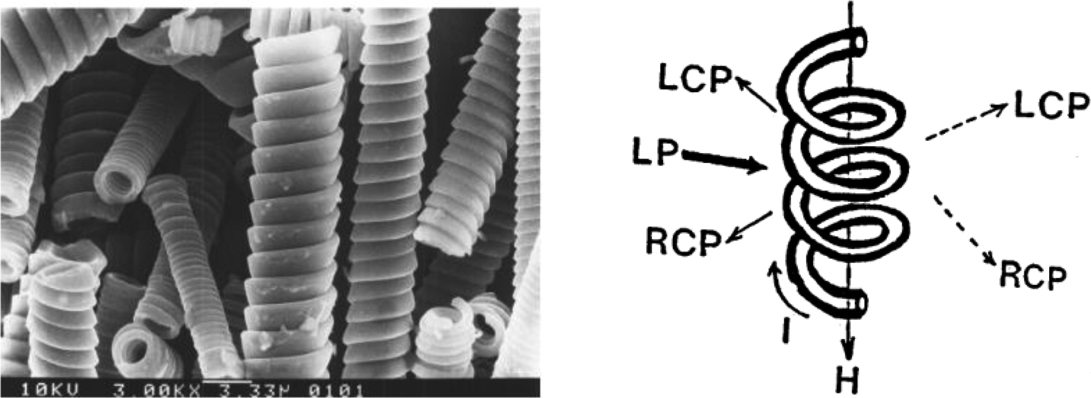
Motojima et al. 11 stated that when the EM wave irradiated on the surface of coiled structures, it gets effectively polarized to form straight and/or circular polarized waves such as right-handed (RCP) or left-handed (LCP) waves along with reflected or dispersed nature. This results in strong attenuation of EM field as shown in Figure 1. Varadan et al. 12 briefly investigated the interaction of EM waves in the chiral materials by analysing the EM wave polarization phenomena occurred due to chiral structure. A relationship was proposed between the incidence and polarized EM waves by the irradiated materials (coiling-chiral materials) as shown in the following equation:

where υ(LP), υ(LCP) and υ(RCP) are the speeds of the linear polarized (LP), right-handed polarized (RCP) and left-handed polarized (LCP) waves, respectively.
In addition, chiral structure attenuates the incidence of EM field in different directions and thus acts as an effective absorptive material in high-frequency region. In a study, Lau et al. 8 stated that coiled carbon nanotubes (CCNTs) are superior to single-walled carbon nanotubes (SWNTs) in hardening the matrix. The flexural strength of the CCNT/epoxy composite was larger than SWNT/epoxy composite. Moreover, good mechanical interlocking between coils and polymer matrix enhanced the fracture toughness of the composites. In another study, Li et al. 13 reported that hardness, elastic modulus and tensile strength of the epoxy composite increase with the increasing content of CCNTs due to tight interlocking of fibres with epoxy matrix. Huang and Dai 14 prepared different carbon structures such as coiled, spring-like, regular helical and double-helical carbon (Figure 2) using the pyrolysis of iron phthalocyanine at low temperature from a carbon source. The physical and thermal properties of carbon helical structures were analysed in comparison with straight carbon structures and found to be superior. Similarly, Zhang et al. 15 investigated the emissivity behaviour of coiled and straight carbon nanotubes. For the same applied electric field, coiled carbon nanostructures showed larger electron emission sites and higher luminance than straight carbon tubes due to a larger number of defect sites in coiled carbon nanostructures.
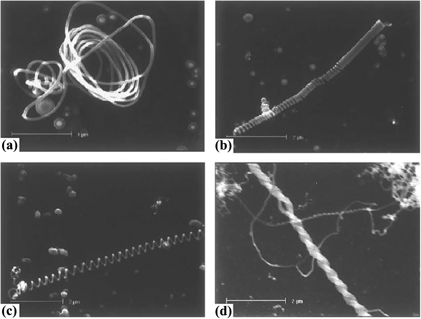
SEM images of carbon nanotubes having (a) coiled, (b) spring-like, (c) regular helical and (d) double-helical structure. 14 SEM: scanning electron microscope.
Park et al. 16 reported that coiled or helical structure of carbon nanotubes affects the EM properties of polymer composites. The composite reinforced with CCNTs exhibited higher conductivity, dielectric permittivity, EM shielding effectiveness than straight carbon nanotube composites. The increase in conductivity might be attributed to the increased number of parallel resistors and capacitors owing to the coiled morphology and formation of several electrical conduction paths. Similarly, Motojima et al. 17 reported that the use of CMCs increases the absorption of EM waves in a high gigahertz (GHz) region. However, at higher CMC content (5–10 wt%), absorptivity decreased due to increased electrical conductivity. From the literature study, it is evident that helical form of carbon improves the absorption behaviour of shields.
The retardation ability of helical structures also depends on the characteristics of core materials used. 18 Since the coiled carbon structure behaves like a solenoid, placing of a ferromagnetic substance in the core of solenoid structure (as shown in Figure 3) may further enhance the absorption behaviour. In this study, helical carbon yarn represents the helical configuration of yarn (not the fibre) around the core yarn. Additionally, the terms helical yarn, coiled yarn and chiral yarns represent the same yarn configuration. Recently, Hwang et al. 19 investigated the SE of silver helical yarn-based knitted fabrics in the frequency range of 300 kHz to 3 GHz. They reported that use of silver yarn as wrapping thread decreases the surface resistance of SS core/silver cover yarn knitted fabric (3.4 log(Ω/sq)) in wale-wise direction. Nevertheless, there were no data reported on absorption and reflection coefficients of fabrics. Hence, the present study investigates the EM absorption behaviour of coiled carbon yarn structures by analysing the absorption and reflection coefficients in C-band region. The preparations of various carbon helical yarns with different helical densities and different finenesses of core SS yarns have been discussed in this article. The plain woven and knitted fabric structures have been prepared and the results of total loss, absorption and reflection coefficients of fabrics have been reported in this article.
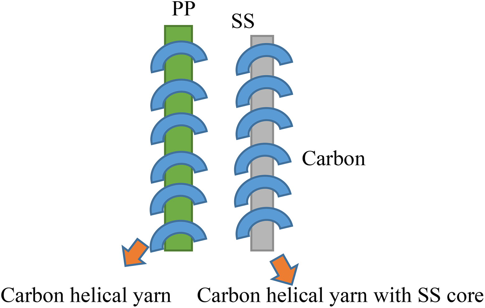
Proposed helical yarn structures for EM shielding. EM: electromagnetic.
The effect of number of fabric layers on absorption coefficient of fabrics has been discussed. In addition, shielding behaviour of composites reinforced with these fabrics has also been investigated and compared with that of fabric form. As reported in the literature, helical structure–reinforced composite could show good mechanical strength. Hence, three-point flexural strength and impact resistance of developed composites have also been reported in this article.
Materials and methods
Materials
A polyacrylonitrile based 3k carbon fibre with fineness of 200 tex (Toray, Japan) and SS multifilaments with fineness of 108 tex (Bekintex, Belgium) were used for preparing the helical yarn. A non-conductive basalt multifilament from Nickunj Eximp ENTP Ltd. (Mumbai, Maharashtra) was used in the core of the helical yarn for better yarn stability. To improve the frictional resistance characteristics of carbon yarn during weaving and knitting processes, polypropylene (PP) fibres (Filament India Ltd., Bhiwadi, Rajasthan) were used. For this purpose, PP fibres of 51 mm stable length were used. The properties of carbon, SS, PP and basalt filaments are listed in Table 1.
Physical properties of filaments used for knitting.
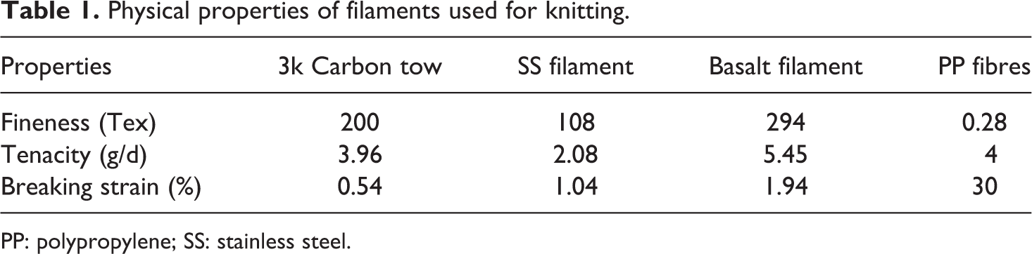
PP: polypropylene; SS: stainless steel.
Preparation of carbon helical yarn
The carbon helical/coiled yarn was prepared in direct twisting machine (supplied by AGTEKS, Istanbul, Turkey) by placing SS and basalt filaments in core and carbon filament as wrapping thread. The density of helical yarn was decided by changing the disc speed and take-up rate of winding package. The image of prepared carbon helical yarn is shown in Figure 4. The prepared helical yarn was made into friction spun yarn in a dref-3 machine (Fehrer, Austria). The other details for preparing friction spun yarn were already described. In this study, carbon helical yarn was prepared with wrapping densities of 50, 100 and 150 TPM.
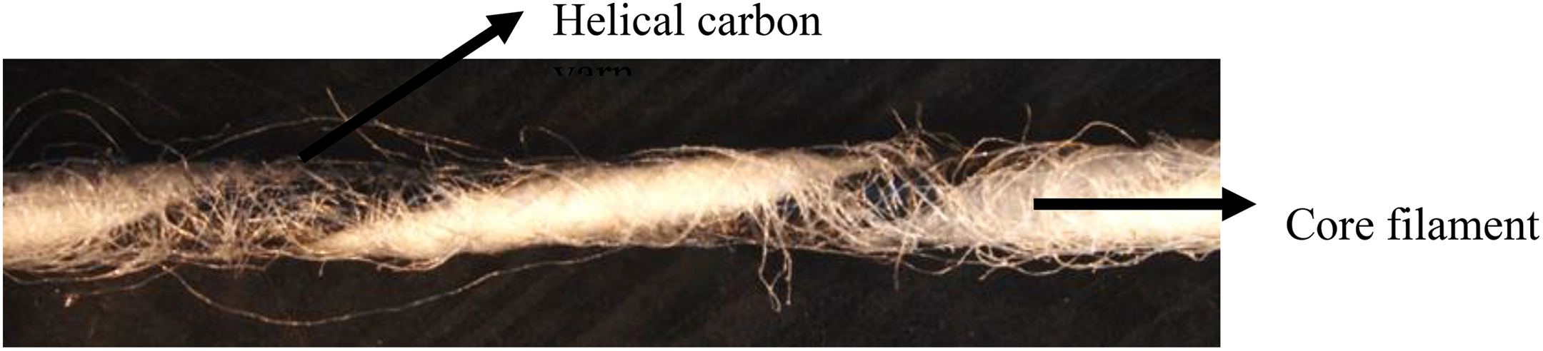
Image of prepared carbon helical yarn.
The following hybrid yarn fabrics were prepared: plain woven fabric, 1/1 plain and 1/1 rib-knitted fabrics. Table 2 shows the variables used in preparing the plain woven fabric. For preparing a woven fabric with a helical yarn density of 50 TPM, both warp and weft directions were used 50 TPM of helical yarn. Similarly, other fabrics were prepared. In the knitted fabric, the numbers of courses and wales were 10 courses/cm and 4 wales/cm, respectively. The loop length in the fabric was 6.85 mm.
Parameters used in preparing the hybrid yarn fabrics.
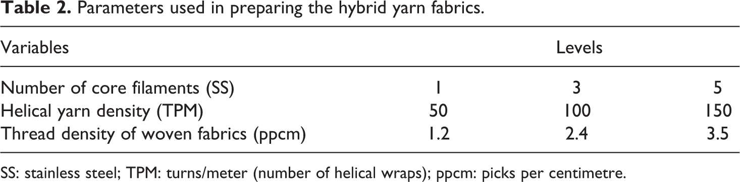
SS: stainless steel; TPM: turns/meter (number of helical wraps); ppcm: picks per centimetre.
Preparation of woven and knitted fabrics
The 1/1 plain woven fabric was made using carbon helical yarn in CCI sample loom with different thread densities. Similarly, 1/1 plain knit (single jersey-SJ) was made in a V-bed flat knitting machine (supplied by G. S. Thind, Punjab) of gauge 4. The schematic diagrams of prepared woven and knitted structures are given in Figure 5.
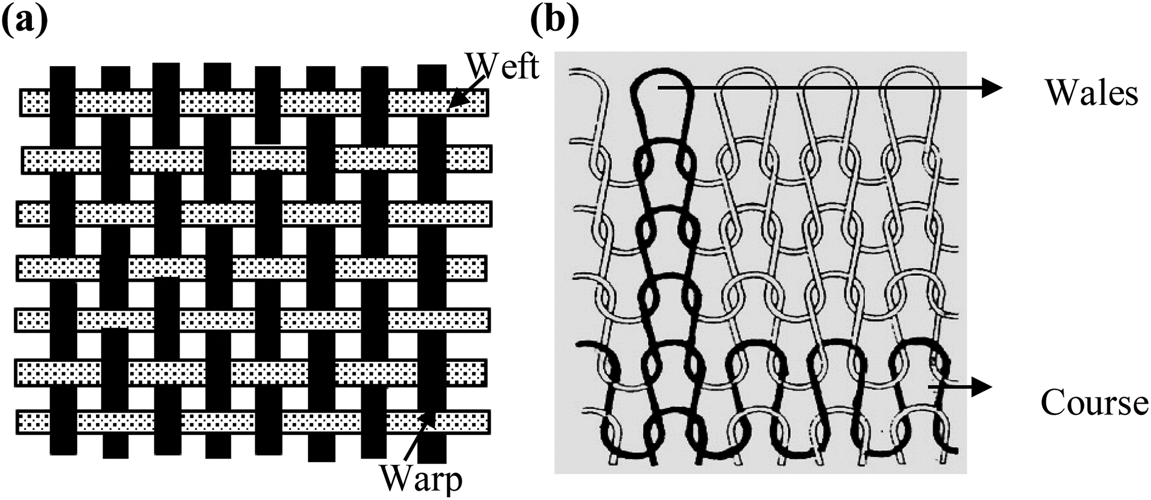
Schematic diagrams of woven and knitted fabrics. (a) 1/1 Plain woven fabric and (b) 1/1 plain knit fabric (single jersey).
Tables 3 and 4 show the specifications of woven and knitted fabrics and their composites prepared in this study. For all the fabrics, warp thread density was kept as 2.75 ends/cm.
Specifications of coiled yarn woven fabrics and composites.
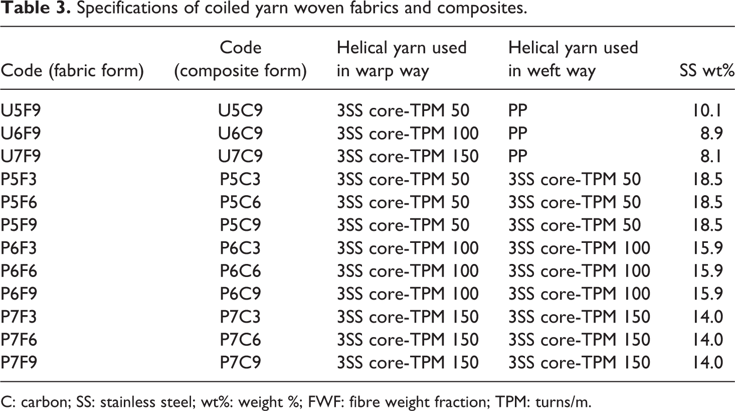
C: carbon; SS: stainless steel; wt%: weight %; FWF: fibre weight fraction; TPM: turns/m.
Specifications of coiled yarn plain knit fabrics and composites.a
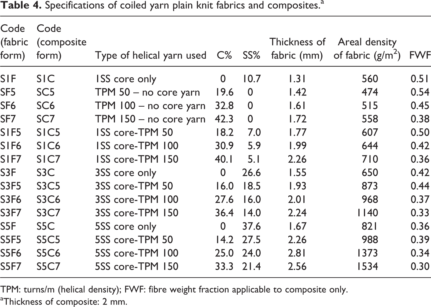
TPM: turns/m (helical density); FWF: fibre weight fraction applicable to composite only.
aThickness of composite: 2 mm.
Preparation of composites
Different woven and knitted fabric composites were prepared by reinforcing the PP resin matrix with the woven and knitted fabrics, respectively. For that purpose, a compression moulding machine is used at a temperature of 180°C for 5 min under a consolidation pressure of 12 bars. After thermal compaction, the composite was cooled down immediately using water cooling. The fibre weight fraction of the composite was quantified using the weight fraction of fibres to the total weight of composite.
Microscopic and scanning electron microscopic image analysis
The surface images of fabrics and cross sections of composites were captured by Optical microscope (Nikon, USA) and SEM EVO-50 (ZEISS, Germany), respectively. The microscopic images of coiled carbon woven and knitted fabrics reveal the surface information such as fibre damage, loop shape and fabric appearance. Similarly, scanning electron microscopic (SEM) images of composites provide fibre geometry, resin penetration and fibre wet out by the resin.
Shielding behaviour of fabrics and composites
The SE and absorption coefficients of fabric and composite specimens were calculated from S11 and S21 parameters of samples measured using waveguide method in C-band region. The SE of material was measured in decibel (dB). The sample size of 2.2 cm × 4.6 cm was prepared. The waveguide was calibrated in air and then sample was placed for assessing shielding effectiveness. Using the following equation, shielding effectiveness of samples is calculated as

where S21 is the scattering parameter obtained for ports 1 to 2. The S11 and S21 values of samples were measured in vector network analyzer (VNA) and total shielding effectiveness of fabrics and composites was calculated using the following equation:

where S21 is the scattering parameter obtained for ports 1 to 2. The absorption (A) and reflection coefficients (R) were calculated using the following equations:

where T means transmission coefficients, ET indicates transmitted electric field, EI indicates incident electric field and ER indicates reflected electric field. In this study, multiple reflections are not considered. The losses due to reflection and absorption were derived from the coefficient values as shown in the following equations:


Flexural rigidity of composites
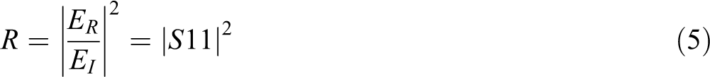
Despite having better attenuation characteristics, shields should also have better impact and flexural rigidity values. Since helical carbon structures improve the mechanical locking of fibres, 13 the flexural rigidity and impact strength of helical yarn–reinforced composites can be higher. Hence, three-point flexural properties of carbon helical composites were determined by Instron three-point bending tester according to the ASTM D 790 standard. 20 The span to depth ratio of 16:1 was chosen for the test. This ensures the failure occur in the outer surface of the sample. The rate of application of bending load was 2 mm/min. Figure 6 shows the load configuration for a specimen and actual test setup used in three-point bending. In Figure 6, F is the applied force, R 1 is the indenter radius, R 2 is the fixed support radius h is the specimen thickness, L is the support span and M is the specimen length. The flexural test was originated by applying the load perpendicular to the direction of fibre. From the load-displacement curves of three-point bending test, flexural strength and modulus were calculated according to the following formula:

where εf is strain in the outer surface, mm/mm (in./in.), D is the maximum deflection of the centre of the beam, mm (in.), L is the support span, mm (in.) and d is the depth in mm (in.).
Load configuration in a specimen and Instron in three-point bending test up. (a) Load configuration for in three-point bending and (b) actual test setup.
Similarly, flexural stress was calculated using the following equation:

where σ is the stress in the outer fibres at midpoint (MPa), P is the load at a given point on the load–deflection curve (N), L is the support span (mm), b is the width of beam tested (mm) and d is the depth of beam tested (mm).
Impact testing of composite
Tinius Olsen impact tester (IT 504) supplied by TINIUS OLSEN Testing Machine Co. Inc. (UK) was used to measure the impact energy of notched composite specimens according to the ASTM D256 test standard. 21 The drop height of 609 mm (24 in.) was used during testing that developed the nominal impact velocity of 3.46 m/s. A specimen notcher was used to make V notch in the composites according to the ASTM D256 standard. Each specimen was tested for five readings and the average value was reported in the study.
Results and discussions
Microscopic image analysis
Figure 7 shows the microscopic images of surfaces of fabrics and composites. The helical yarns were converted into fabrics without disturbing the fibres of helical structures (Figure 7(a) and (b)).
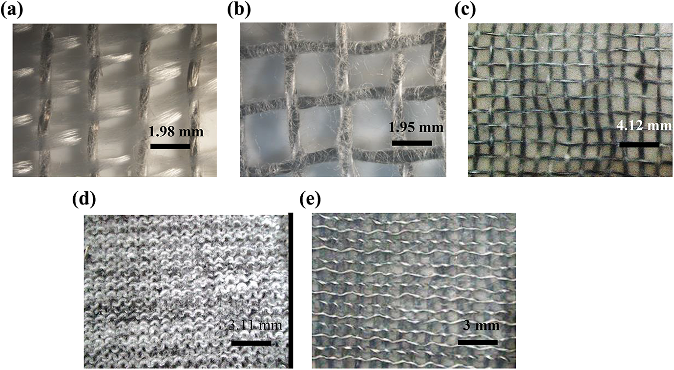
Microscopic images of fabric and composite specimens. (a) USF9 (UD fabric), (b) P5F9 (woven fabric), (c) P5C9 (woven composite), (d) S5F5 (SJ fabric) and S5C5 (SJ composite).
In the composite form, sheath PP fibres present on helical yarns melts and forms contacts between fibre and fibre surfaces (Figure 7(c)). Similarly, the surface of the helical yarn plain knit fabric sample is shown in Figure 7(d). The plain knitted fabric shows the completely closed structure due to the presence of sheath fibres. However, the composite shows open structure due to melting of surface PP fibres during composite preparation (Figure 7(e)). From the surface image analysis, it is evident that helical yarns can be made into woven and knitted fabrics without damaging the structure.
SEM images of composite cross sections
In order to understand the resin impregnation inside the helical carbon structures, SEM images of cross sections of carbon helical yarn composites have been analysed as shown in Figure 8.
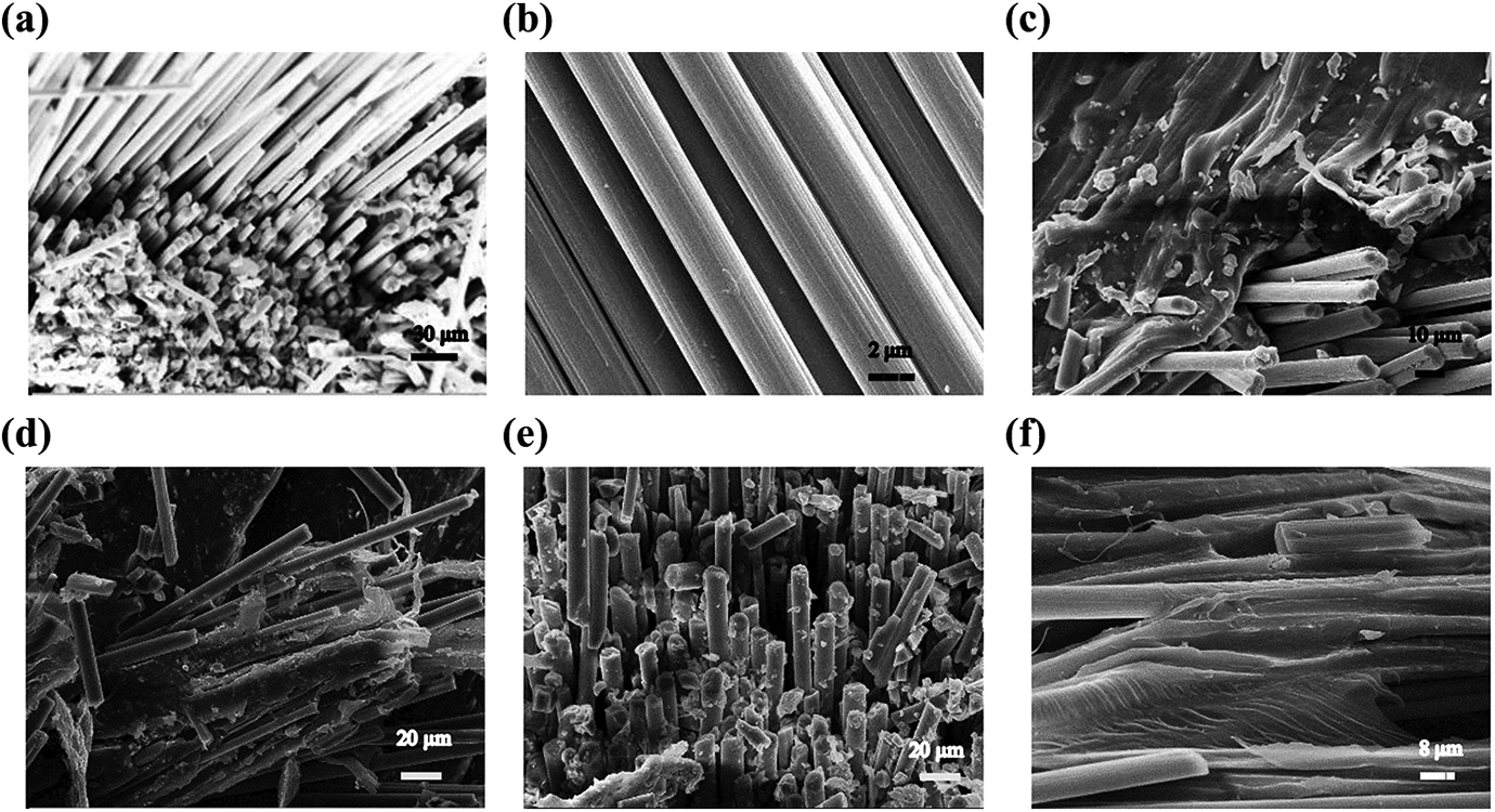
SEM images of coiled carbon yarn composites. (a) Carbon fibres (unimpregnated), (b) SS fibres (unimpregnated), (c) S1C6, (d) S1C7, (e) S3C5 and (f) S3C6. SEM: scanning electron microscope.
The SEM images of un-impregnated carbon and SS fibre bundles are shown in Figure 8(a) and (b), respectively. As observed in Figure 8(c) to (f), the molten PP resin has penetrated well inside the fibre bundles during composite preparation. This results in individualization of each fibre in the bundles and fibre to fibre contact is decreased. 22 However, it improves the contacts between core and helical fibres. The fibre wet out seen in SEM images confirms that helical configuration of carbon fibres might have disturbed during the process of resin impregnation. Also, the fibre wet out ensures better interface formed between fibre and PP resin matrix.
Shielding behaviour of coiled yarn woven fabrics and their composites
The shielding characteristics of fabrics and their composites differ due to the penetration of resin inside the fibre bundles. In the coiled yarn structure, resin penetration happens into the coiled fibres as well as into core fibres. Thus, the induced EM motive force in the coiled yarn composites changes resulting in a different shielding behaviour of composites. Hence, the shielding characteristics of fabric and composites have to be investigated in detail.
In fabric form
Figure 9 shows the shielding behaviour of coiled yarn woven fabrics in C-band region. From Figure 9(a), it is observed that unidirectional coiled yarn fabric (U5F9) shows the SE of −5 to −10 dB in the frequency range of 4–8 GHz. When the coiled yarn is placed in both warp and weft directions of the fabric, SE is increased.
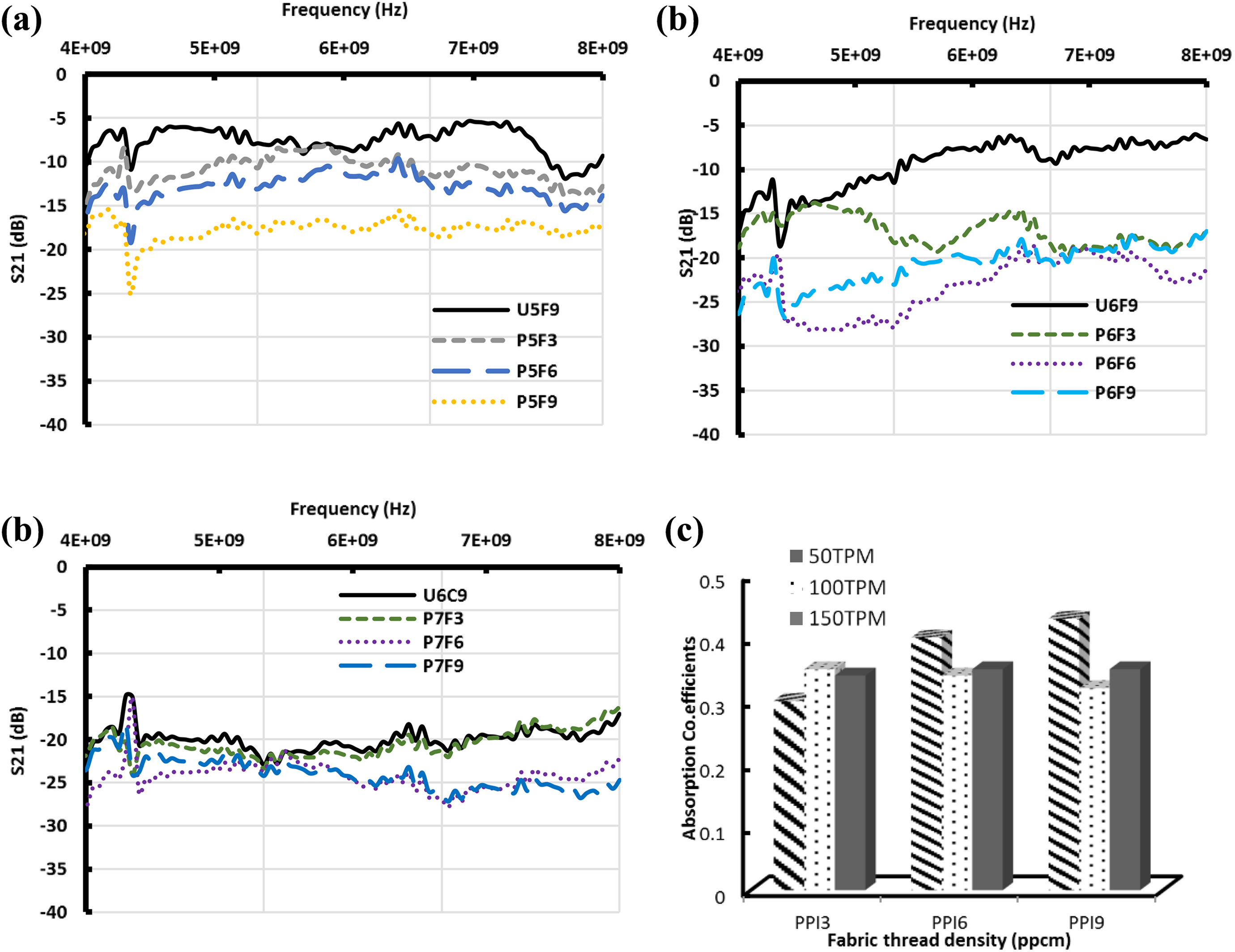
SE and absorption coefficients of coiled yarn woven fabrics. (a) Wrapping density of 50 TPM, (b) wrapping density of 100 TPM, (c) wrapping density of 150 TPM and (d) adsorption coefficients of woven fabrics.
In low wrapping density (50 TPM), the increase in thread density of fabric increases the SE from −8 to −19 dB. When the wrapping density is multiplied to 100 TPM, the increase in thread density of fabric initially increases the SE of fabric. However, after 6.85 GHz, there is not much difference in SE of fabric observed as seen in Figure 9(b). This may be due to fibre skin effect. In case of higher wrapping density, that is, 150 TPM, the increase in thread density from 2.36 to 3.54 picks per centimetre (ppcm) has not improved the attenuation level of the fabric (Figure 9(c)). This is due to the fact that beyond certain level, metal content will not influence the SE of fabric. The woven fabrics were also analysed for absorption coefficient. Figure 9(d) shows the absorption coefficients of coiled yarn woven fabrics in the frequency of 7.26 GHz. It has been observed from Figure 9(d) that the increase in wrapping density of yarns increases the absorption coefficients of fabrics. However, at higher wrapping density, coefficient of absorption decreases. This is due to lower stability of coiled yarn structures that reduces the absorption coefficient and increases the reflection coefficient of fabrics. Similarly, the increase in thread density increases the absorption coefficients of fabrics to an extent. However, at higher thread density, the improvement in absorption coefficient is not high, hence fabric behaves like a metal. Similar to woven fabrics, shielding behaviour of woven fabric–reinforced composites was also investigated in C-band region.
In composite form
Figure 10 shows the total shielding effectiveness and absorption coefficients of coiled yarn woven composites. Compared to unidirectional coiled yarn composites, a higher SE is observed for coiled yarn woven composite at the thread density of 1.18 ppcm. Similarly, the composite with a thread density of 3.54 ppcm shows larger SE of −20.5 dB. This phenomenon is observed for a helical yarn density of 50 TPM (Figure 10(a)). However, the composite with a thread density of 2.4 ppcm does not show much improvement in shielding effectiveness. This trend is not seen for a helical yarn density of 100 TPM (Figure 10(b)). At higher wrapping density (150 TPM), the increase in thread density improves the SE of composites as observed in the fabric form (Figure 10(c)). This is due to the presence of more metal content and formation conductive network in the composite. The shielding behaviour of composite was compared with that of the fabric form. It has been observed that the composite shows higher SE than that obtained in the fabric form at low wrapping density (50 TPM). This is attributed to formation of new conducting points at interlacement points. 22 However, a reverse trend is observed for higher wrapping density. The composite having a wrapping density of 100 TPM shows lower SE (around −5 to −10 dB) than the fabric form. This is due to the fact that the penetrated resin in the coiled yarn disturbs its chiral structure as a result, SE is decreased.
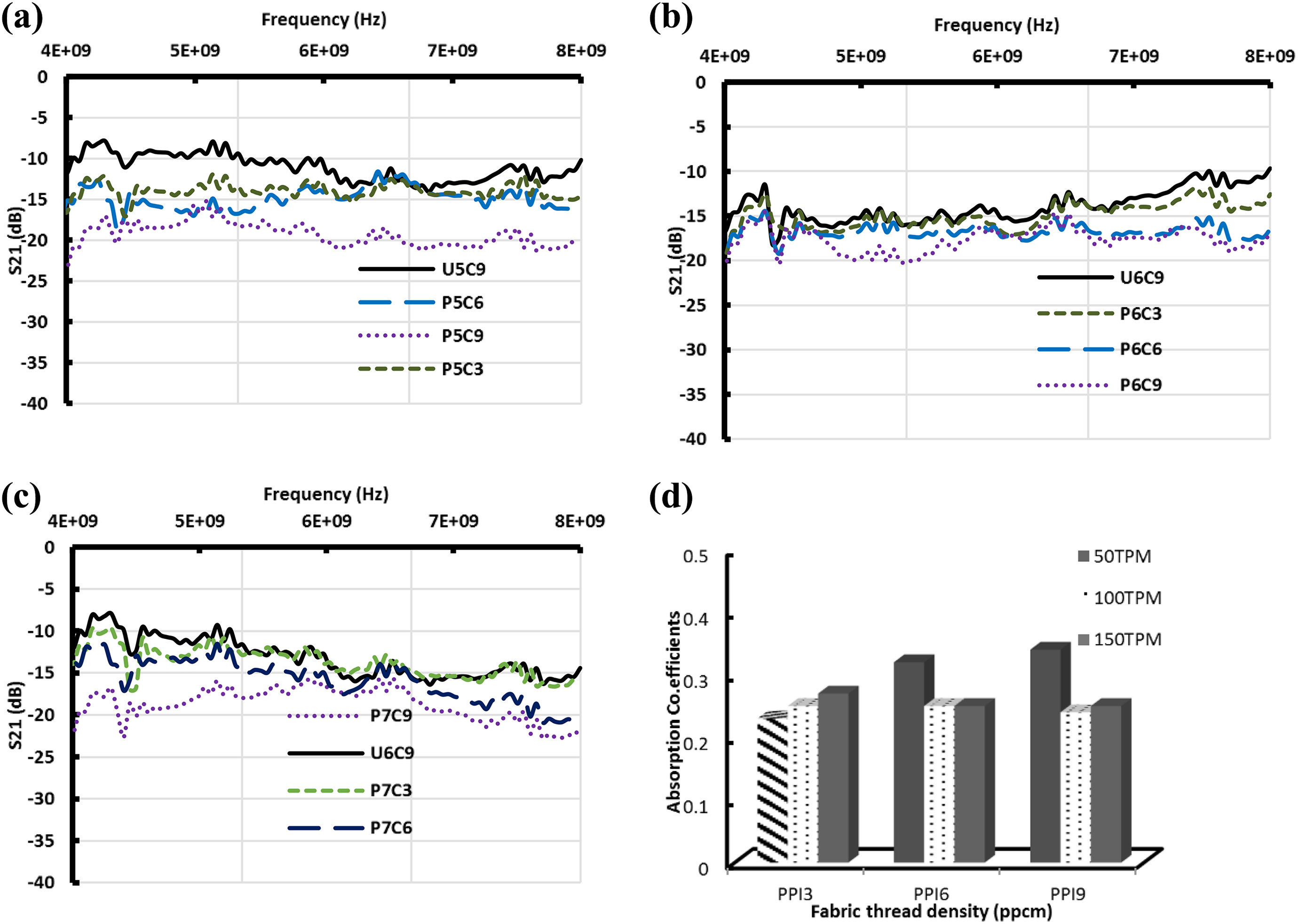
SE and absorption coefficients of coiled yarn woven composites. (a) Wrapping density of 50 TPM, (b) wrapping density of 100 TPM, (c) wrapping density of 150 TPM and (d) adsorption coefficients of woven fabrics.
Moreover, the penetrated resin separates out each fibre in the yarn (as seen in the SEM images) and hence continuity of the yarn is also affected. The similar case was observed for composites having helical yarn of 150 wraps/m. Similar to shielding behaviour, the absorption coefficient was analysed for all the composites. The results are shown in Figure 10(d). It has been observed from Figure 10(d) that woven composites show lower absorption coefficients than that obtained in the fabric form. This is due to disturbed coiled structure of yarns during composite preparation. However, composites having lower wrapping density display relatively higher absorption coefficients than that with higher wrapping density. This is due to more stability of low wrapping density yarns. Similar to woven structures, absorption behaviour of knitted coiled yarn fabrics was investigated in C-band region.
Shielding behaviour of plain knit fabrics
The 1/1 plain knitted fabrics prepared from carbon coiled yarn (shown in Table 4) were investigated for SE in C-band region. The fabrics were tested in both course and wale directions in C-band waveguide and absorption coefficients were calculated using S parameters.
In course direction
The shielding effectiveness of plain knit fabrics (single jersey) was investigated in course direction. The values of S11 and S21 are shown in Figure 11. The increase in SS core thread density from one to three SS filaments increases the total SE (S21) of fabrics as seen in Figure 11(b). Similarly, when the carbon coiling density is increased from 50 to 150 wraps/cm, the SE of fabrics is also increased. This is attributed to the presence of more amount of metal fibres that increases the SE of fabrics. For investigating the reflection and absorption nature of fabrics, S11 values were analysed. The results are shown in Figure 11(a). It has been observed from Figure 11(a) that the values of S11 of fabrics are closer to −1 or −2 dB. This indicates that all the fabrics behave like a metal and reflects all the signals. The absorption coefficients of fabrics are found to be very less, and values lie in the range of 0.19–0.35. Hence, coiled yarn single jersey fabrics exhibit reflective shielding in course direction. Since the yarns are connected continuously in course direction, the fabric shows larger conductivity and hence reflects the incident EM waves. However, with respect to increase in frequency, the S11 and S21 values of fabrics remain the same except for few samples. The effect of number of fabric layers on shielding effectiveness was examined. Out of all, fabrics having lower number of core SS filaments with wrapping density of 50–150 TPM show an improvement in S11 values compared to other fabrics.
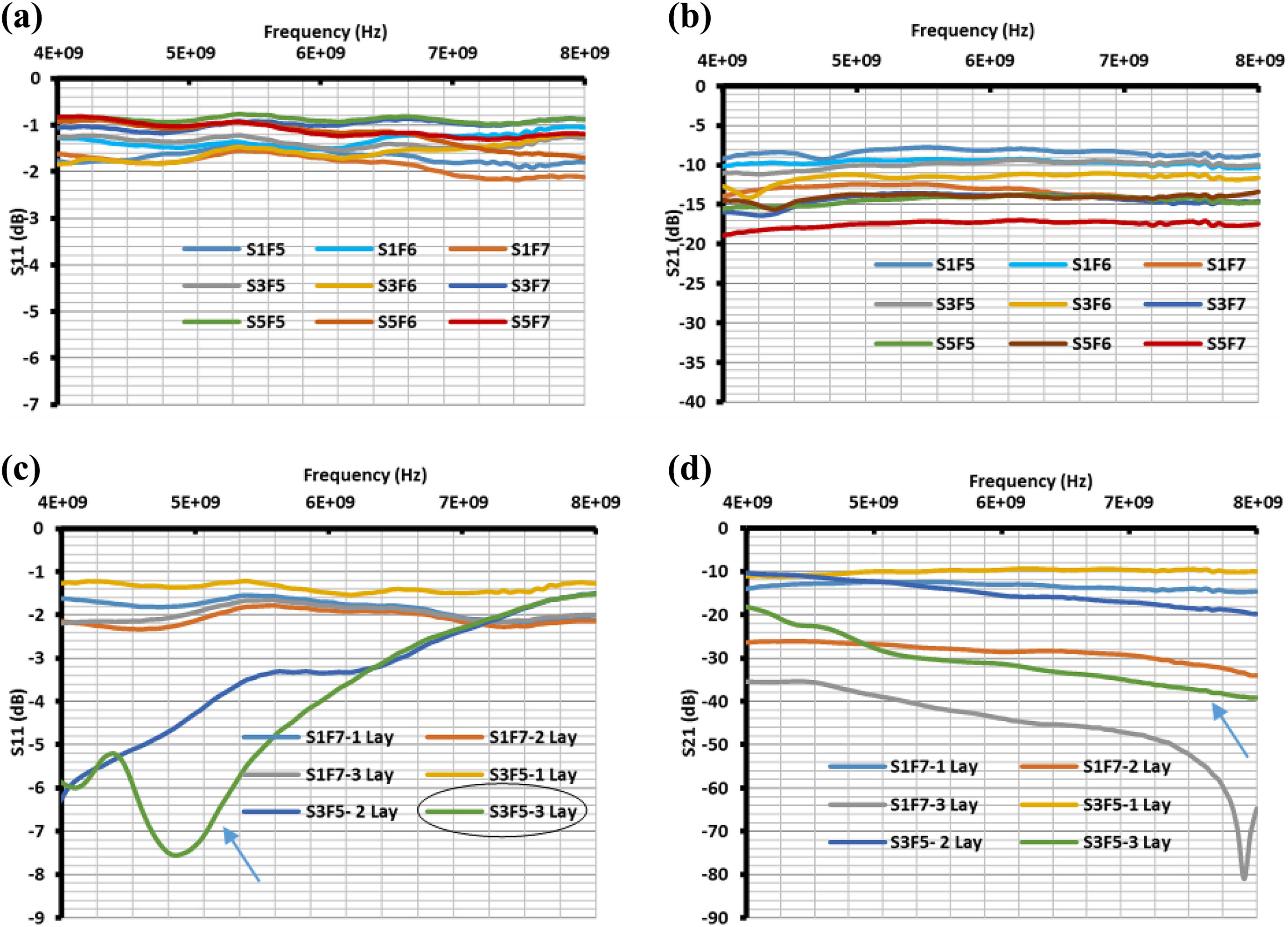
S11 and S21 behaviours of single and multilayer fabrics in course direction. (a) S11 values of plain knit fabrics, (b) S21 values of plain knit fabrics, (c) S11 values of S1F7 and S3F5 fabrics and (d) S21 values of S1F7 and S3F5 fabrics.
In order to study the absorption behaviour, layers of S1F7 and S3F5 fabrics were varied and the SE of fabrics was studied. Figure 11(c) and (d) show the S11 and S21 values of S1F7 and S3F5 fabrics with different fabric layers. From Figure 11(d), it is seen that total shielding effectiveness of fabric increases with the increase in fabric layers. The fabric shows the total SE of −10 to −50 dB for increasing the fabric layers from one to three layers at 7.3 GHz. In addition, increase in core SS filaments and coiling density of carbon also improves the SE of fabrics due to increased metal content. However, the values of S11 are not as high as those observed in Figure 11(c). The S11 values lie in the range of −1 to −8.5 dB for the increasing number of fabric layers. This indicates that fabric tends to show the absorption behaviour instead of metal characteristics. This is due to the increase in absorption loss by means of increased fabric layers and thickness of the structures. For example, absorption coefficient of single layer S3F5 fabric sample is 0.205, whereas it is improved to 0.819 for three layers of fabrics. This indicates that fabric tested in course direction shows higher SE mostly by reflection. However, an increase in fabric layer improves the absorbing nature of fabrics. Similarly, shielding behaviour of fabrics tested in wale direction was investigated. The findings are reported in the next section.
In wale direction
Figure 12 shows the S21 values of fabrics having only core SS filaments as well as only carbon helical yarns. From Figure 12(a), it can be observed that SF6 fabric shows the absorption loss of 4.87 dB and reflection loss of 0.54 dB.
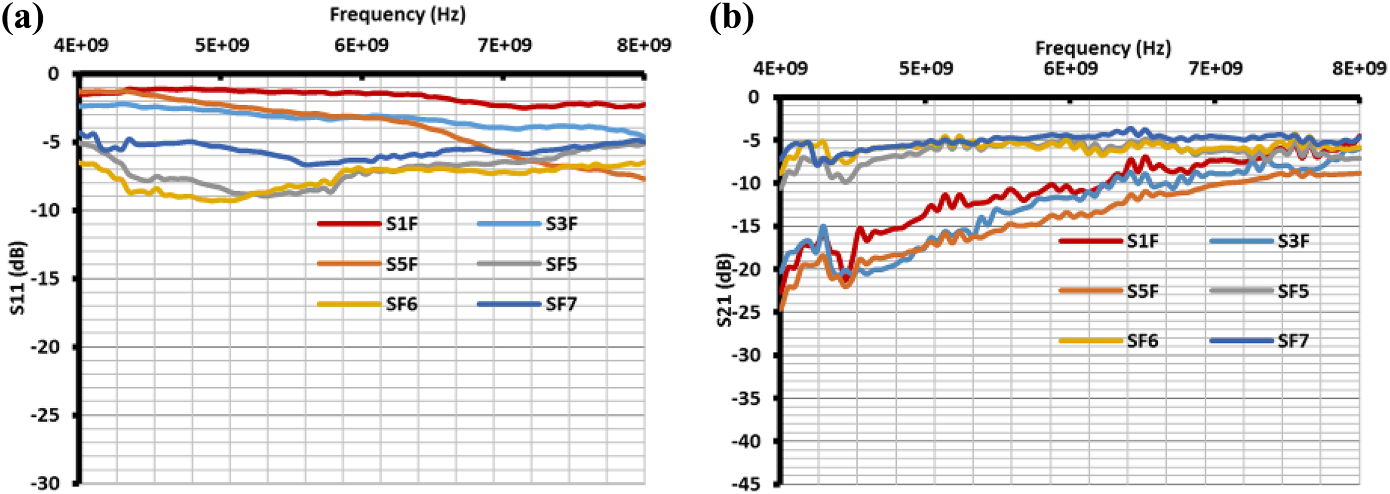
Shielding behaviour of fabrics having carbon helical yarns in wale direction. (a) S11 values of carbon helical yarn fabrics and (b) S21 values of carbon helical yarn fabrics.
This indicates that carbon coiled yarn fabrics exhibit absorption behaviour. This is attributed to the formation of electromotive force in the coiled fibre that enhances the absorption behaviour of fabrics. However, the increase in coiled yarn density from 100 to 150 TPM decreases the absorption behaviour of fabrics. This may be due to instability of coiled yarn structures at higher wrapping density. In addition, total SE of fabric is not changed significantly for the increase in coiling density of carbon fibre from 50 to 150 TPM (Figure 12(b)). Nevertheless, the increase in core filaments increases the total SE of fabrics. The increase in frequency of incident EM wave has negative influence on SE of fabrics due to fibre skin effect. When the core SS filament is introduced in the coiled yarn, the shielding behaviour of fabrics is changed entirely. Figure 13 shows the S11 and S21 values of fabrics having helical carbon with SS core yarns.
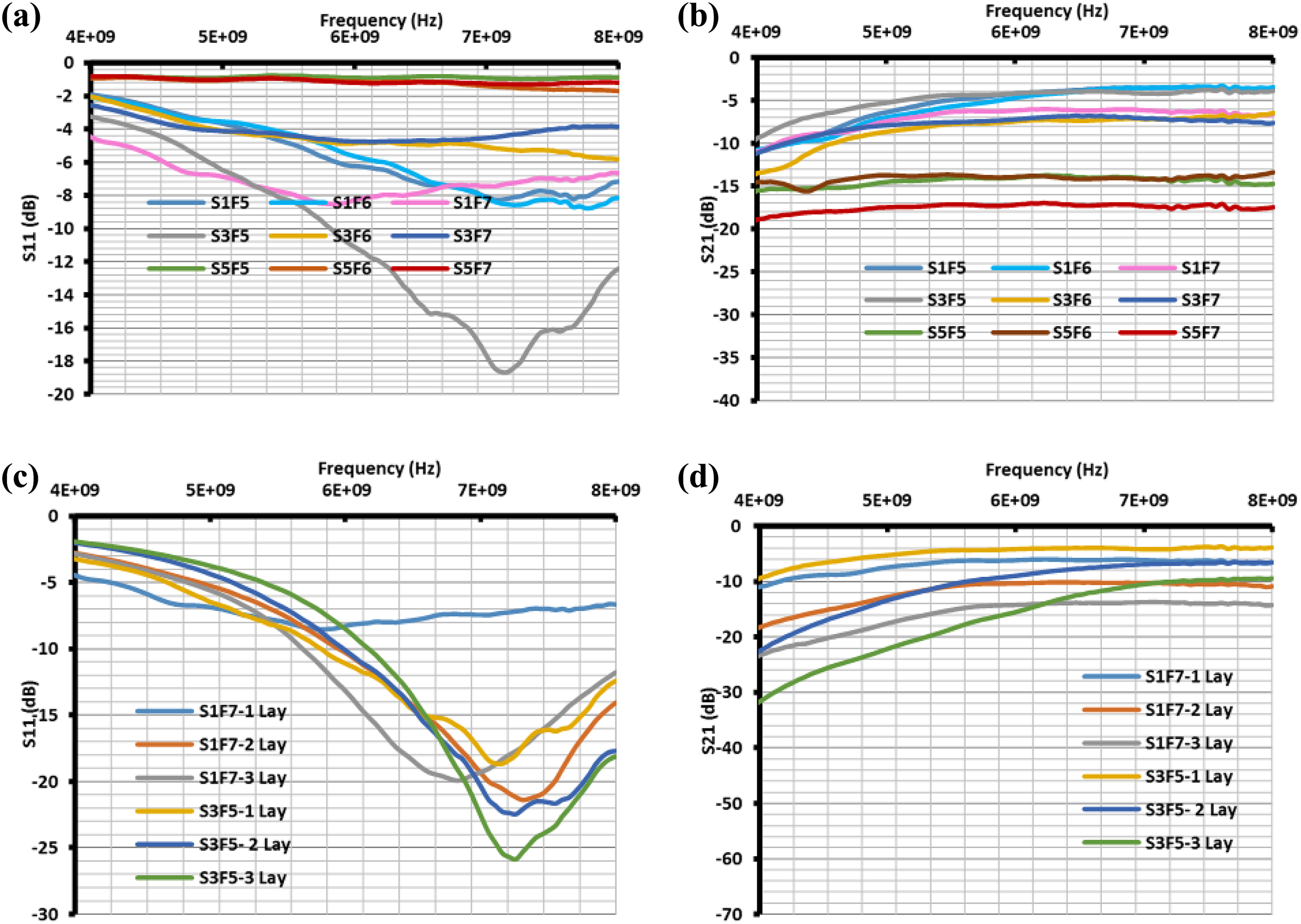
S11 and S21 parameters of single jersey knitted fabric samples in wale direction. (a) S11 values of plain knit fabrics, (b) S21 values of plain knit fabrics, (c) S11 values of S1F7 and S3F5 fabrics and (d) S21 values of S1F7 and S3F5 fabrics.
The increase in wrapping density of yarn from 50 to 150 TPM does not improve the overall shielding effectiveness of fabrics except some cases (Figure 13(b)). However, the increase in core SS filaments in the yarn increases the overall SE of fabrics due to increased permeability of the fabric sample. From Figure 13(a), it is seen that S11 value of S3F5 fabric reaches to −18.6 dB, which confirms the respective fabric can have larger absorption coefficient. Similarly, S1F7 fabric shows the S11 value of −8.46 dB. This is due to the presence of ferromagnetic core material (SS) in the carbon coiled yarn. Upon incidence of EM radiation, an electromotive force (EMF) is developed in the chiral structures. 23 The developed EMF magnetizes the core SS fibres that resulting in increased absorption of EM radiation. By comparing the S11 values of all nine fabrics, S1F7 and S3F5 fabrics show higher S11 values. Hence, both the fabrics were considered for further investigation. Figure 13(c) and (d) show the S11 and S21 values of S1F7 and S3F5 fabrics at different number of fabric layers. It is observed from Figure 13(c) and (d) that increase in fabric layers increases the absorption behaviour of fabrics.
Especially, S11 value of S3F5 fabric increases from 18.6 to 25.6 dB at 7.2 GHz. As the number of fabric layers is increased, the total SE of the fabric is also increased from 4.1 to 10.1 dB. This indicates that the fabric structure slowly turns into complete EM absorbing structure. This is due to higher thickness of the fabric. As the frequency is increased, the attenuation level of sample is decreased drastically as shown in Figure 13(d). This is due to larger penetration of incident EM waves of shorter wavelengths in the fabric. However, the S11 value keeps increasing and reaches the stable value where absorption is maximum for the structure (Figure 13(c)). Compared to course direction, single jersey fabrics exhibit higher absorption coefficients in wale direction. This is attributed to the fact that the presence of carbon fibres in wale direction of fabric is parallel to the applied electric field that increases the EMF in the carbon coil. The induced EMF increases the magnetization of core SS fibres and hence total SE is increased. Especially, the S1F7 and S3F5 fabrics show better EM absorption behaviours. The absorption and reflection coefficients of these fabrics were analysed. The findings are reported in the next section.
Absorption and reflection coefficients of single jersey fabrics
The absorption and reflection coefficients of all the plain knit fabrics were calculated using the values of S-parameters. Figure 14 shows the effect of helical wrap density and core filaments on absorption coefficients of single layer plain knit fabrics. When the core SS filament is increased from one to three, the absorption coefficient decreases. This is due to less magnetization of SS filaments by the lower number of carbon helical wraps.
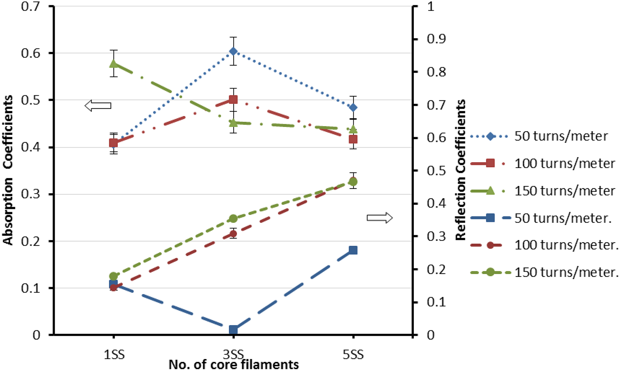
Reflection and absorption coefficients of single jersey fabrics.
However, an increase in helical density slightly increases the absorption coefficient. Also, the reflection coefficient is increased from 0.01 to 0.35 and the total SE is increased. The increase in core SS filaments from 3 to 5 decreases the absorption coefficient to 0.48 and increases the reflection coefficients of fabrics. This is due to increased conductivity of fabric samples due to the presence of larger metal content that supports reflective shielding behaviour. 11 Hence, it can be said that for a constant helical density, increase in core SS filaments initially increases the absorption coefficient and then decreases (Figure 14). Especially, fabric having 3SS core filaments with lower helical density (50–100 TPM) shows higher absorption coefficients in the frequency level of 7.26 GHz. This indicates that the presence of certain amount of SS fibres is required for easy magnetization by helical carbon yarns. 3 Hence, a particular fabric type shows larger attenuation by absorption. However, an increase in core SS filaments increases the reflection coefficient of fabrics. The absorption and reflection coefficients of fabrics also depend on the number of fabric layers. Figure 15 shows the absorption coefficients of coiled yarn fabrics at different number of fabric layers. It has been observed from Figure 15 that increase in number of fabric layers increases the absorption coefficients of fabrics for all type of helical yarns.
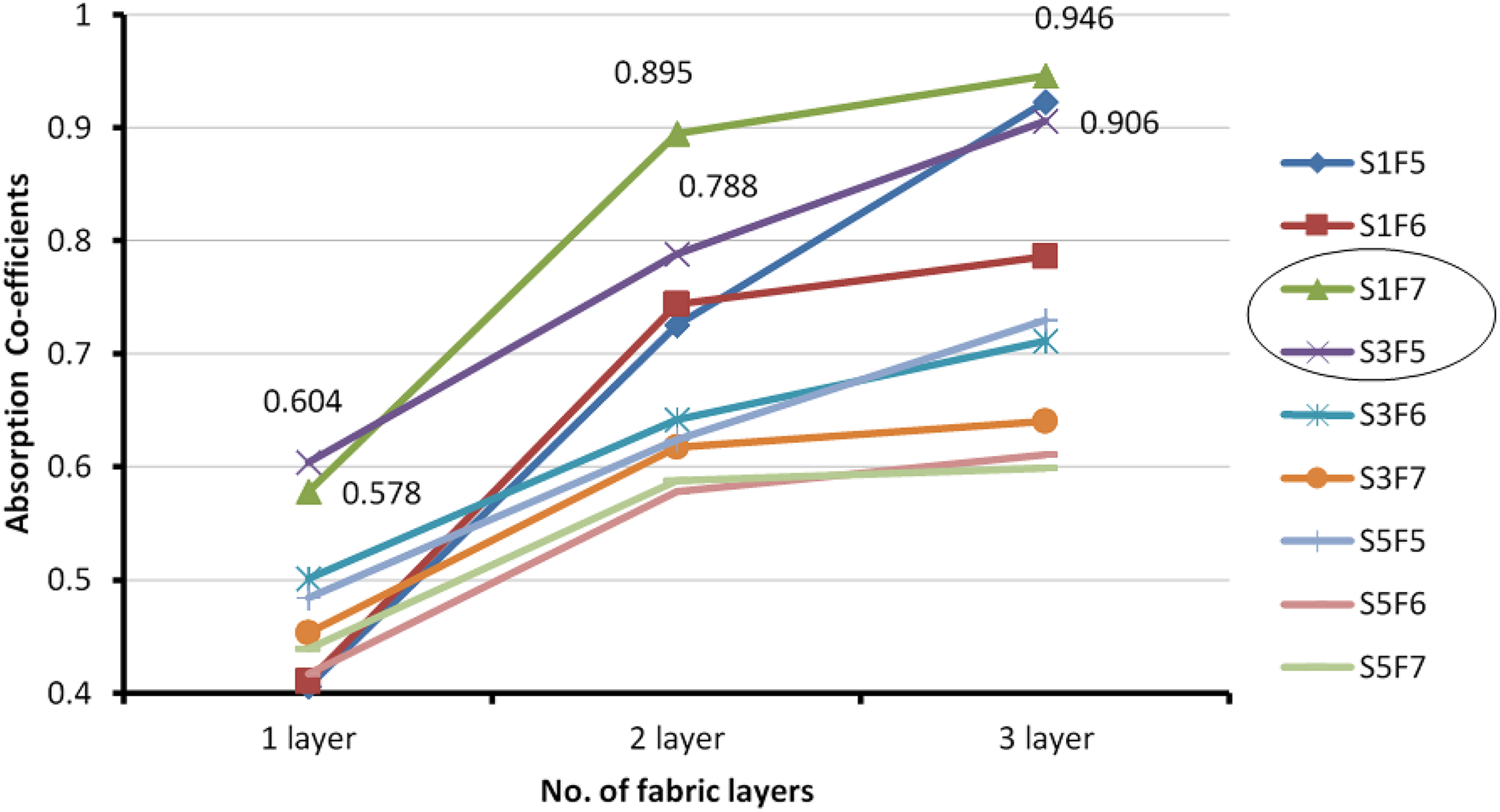
Number of fabric layers on absorption coefficients of fabrics.
Especially, S1F7 and S3F5 fabrics show highest absorption coefficients compared to other fabrics. This is due to easy magnetization of core SS filaments in S1F7 and S3F5 fabrics. When the number of fabric layers is increased to three, the fabric structure shows maximum attenuation by absorption (0.946). This is due to the increase in thickness of the structure that helps in absorbing more amount of EM radiation. Kang and Kim 24 also observed the improved absorption behaviour for carbon microcoiled structures when the thickness of the fabric is increased. Similar to fabrics, composite specimen made from these fabrics was analysed for shielding behaviour.
Shielding behaviour of composites reinforced with plain knit fabrics
In order to understand the shielding behaviour of composites, the helical yarn plain knit fabric samples were made into composites. Figure 16 shows S11 and S21 values of plain knit fabric composites. From Figure 16(a), it is observed that the S11 values lie in the range of 0 to −3.5 dB. This indicates that all the composites behave like a metal.
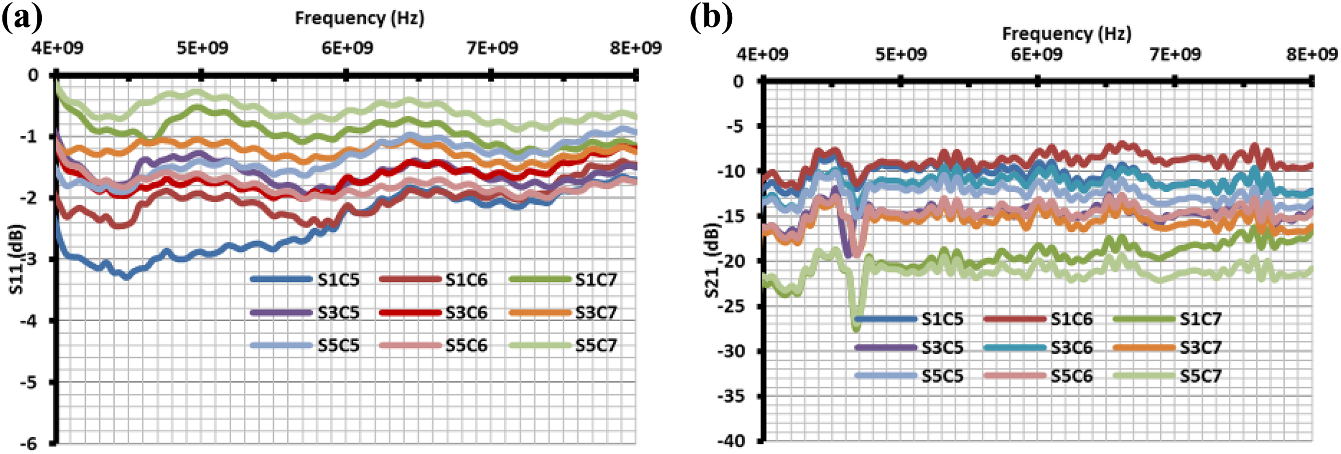
(a) S11 and (b) S21 values of coiled yarn plain knit fabric composites.
Hence, the prepared composites exhibit almost zero attenuation by means of absorption. This is due to the presence of molten PP polymers in the structure instead of air that changes the reflection and absorption nature of incident EM waves. 25 However, the composites show total shielding effectiveness of 20–30 dB (Figure 16(b)). In addition, the overall SE of composite is increased drastically compared to fabric form. In the composite, PP fibres covered on carbon and core SS filaments get molten and a physical contact is formed between the core SS filaments and outer carbon filaments. This results in less magnetization effect of core SS fibres. Moreover, coiled structures are disturbed due to penetrated resin that changes the EM absorption behaviour of composite. Hence, the total composite structure behaves more like a metal. This trend is observed for all the composites. It is understood from this study that coiled carbon structure is more effective in fabric form that functions like an EM absorber with high absorption coefficients. Nevertheless, in the composite form, it behaves like a metal due to the penetrated resin in the coiled structures that changes the induced EMF in the coiled fibres resulting in reflective shielding effect.
Mechanical behaviour of developed fabric composites
The flexural strength and impact energy absorption behaviours of coiled yarn woven and knitted composites were measured in Instron three-point bending tester and Tinius Olsen impact tester, respectively. The following section discusses the mechanical behaviour of coiled yarn woven and knitted composites in this study.
Three-point bending test
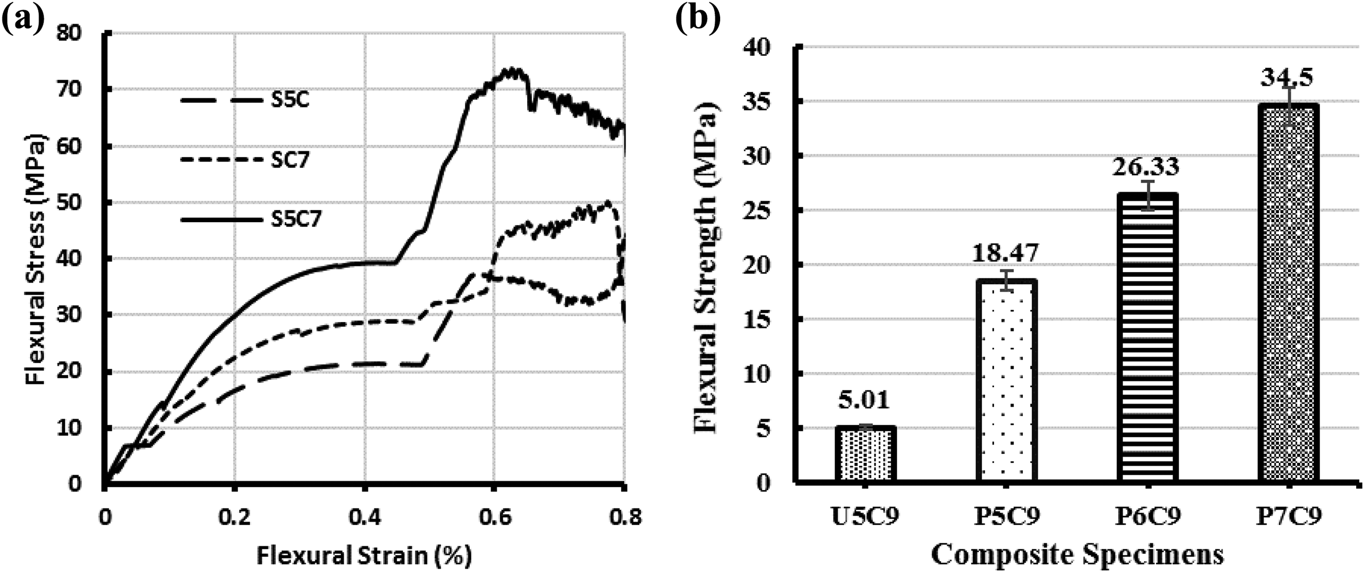
The stress–strain behaviour of carbon coiled yarn fabric–reinforced PP composite was analysed under flexural loading. The results are shown in Figure 17. It can be observed from Figure 17(a) that coiled carbon yarn with SS core knitted composite (S5C7) shows a larger flexural stress value of 73 MPa than carbon coiled yarn composite (48.3 MPa) (SC7) and SS core yarn composite (S5C).
Three-point bending test for knitted and woven fabric composites.
This indicates that the presence of core and coiled fibres improves the flexural strength of the composite. Similarly flexural stress, strain and modulus values of plain knit fabric composites were measured. The values are shown in Table 5. It is seen from Table 5 that increase in coiling density increases the flexural strength of the composite from 26.57 to 31.01 MPa.
Flexural properties of 1/1 plain knit composites.
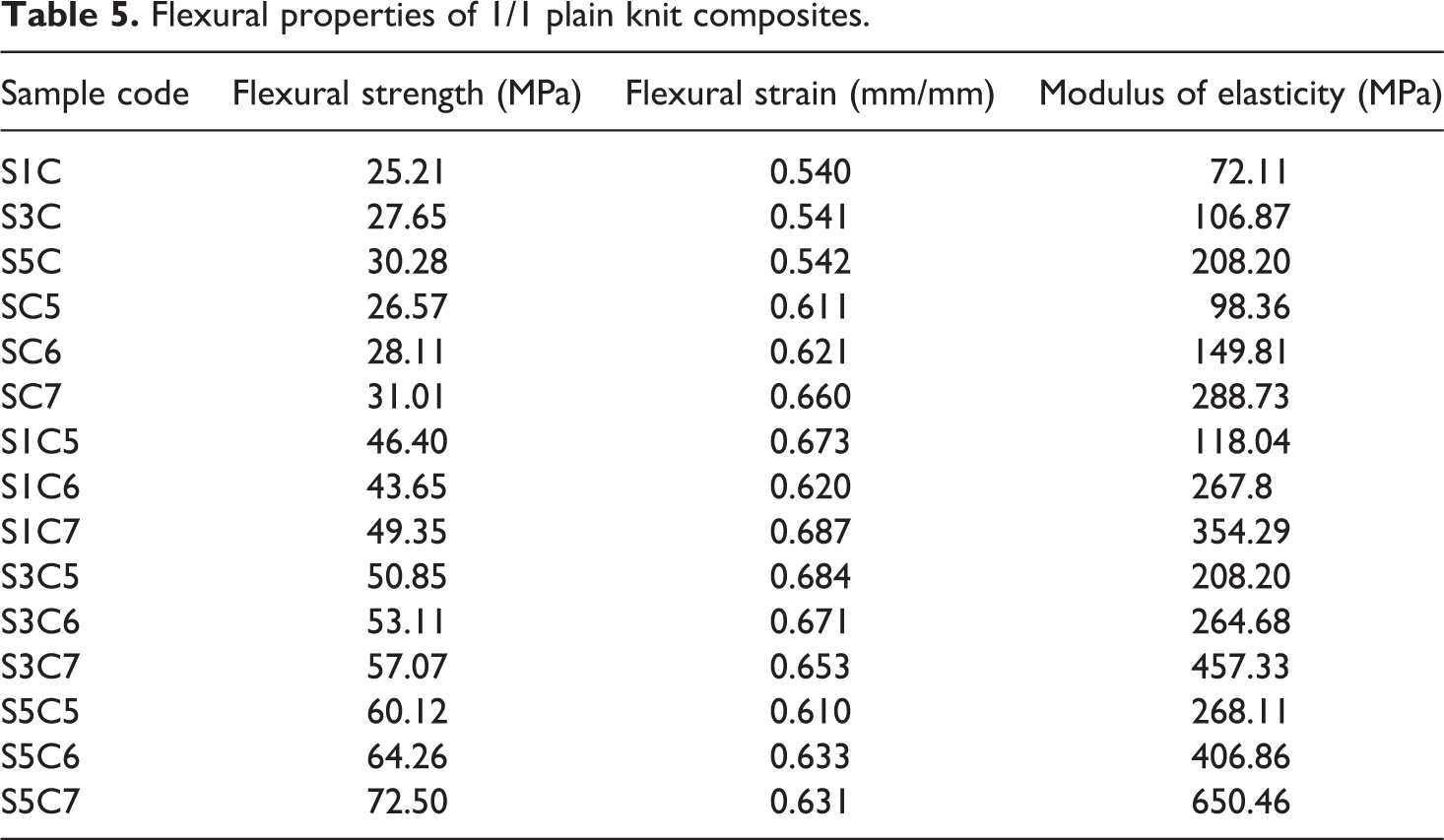
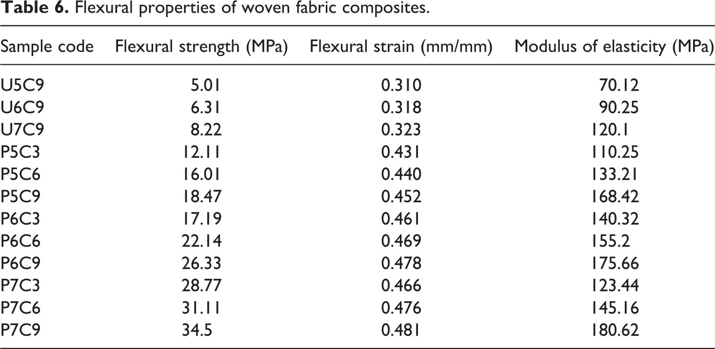
This is due to interlocking of resin by the coiled carbon structure that enhances the strength and as modulus of elasticity of the composite. Moreover, increase in coiling density also improves the flexural strain rate and elastic modulus of the composite. This is due to uncoiling nature of carbon fibres upon loading, which results in increased elastic modulus. Similar to plain knit structure, coiled yarn woven composites were investigated for flexural stress and strain %. The values are reported in Table 6. It has been observed from Figure 17(b) that unidirectional coiled yarn composites exhibit lower flexural strength of 5.01–8.22 MPa and strain % of 0.31%. However, the bidirectional coiled yarn woven composites exhibit larger flexural strength. The increase in thread density also increases the flexural strength of fabric composite (Table 6). This is due to increasing fibre content that shows larger resistance towards flexural force. The modulus of elasticity is also higher for increasing the coiling density and number of core filaments. From this study, it is observed that the coiling density and number of core filaments decide the flexural strength of composites.
Flexural properties of woven fabric composites.
Impact testing of composites
The microscopic and SEM images of tested composites (under impact force) were captured. The images are displayed in Figure 18. All the woven and knitted composites followed complete failure under impact load. The broken sample of S5C7 is shown in Figure 18(a).
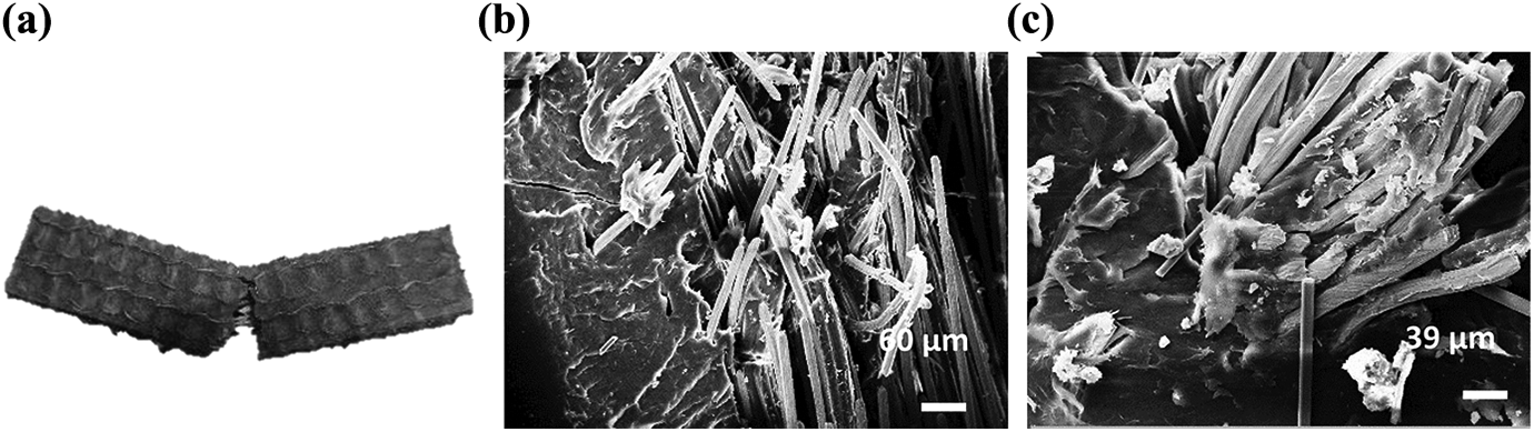
SEM images of fractured specimens by impact testing. (a) Broken composite (S5C7), (b) broken fibres in woven composite (P7C9) and (c) broken fibres in knitted composite (S5C7). SEM: scanning electron microscope.
It is observed from Figure 18(b) and (c) that fibres get completely broken in woven and plain knit composites after subjected to the impact force. As well as, a good fibre wet out is observed around the fibre that ensures good fibre–resin interaction. Figure 19 shows the impact energy absorption of woven and knitted coiled yarn–reinforced PP composites. The impact energy absorption behaviour of helical yarn woven composites is shown in Figure 19(a). From Figure 19(a), it is seen that pure PP composites show energy absorption of 0.133 J.
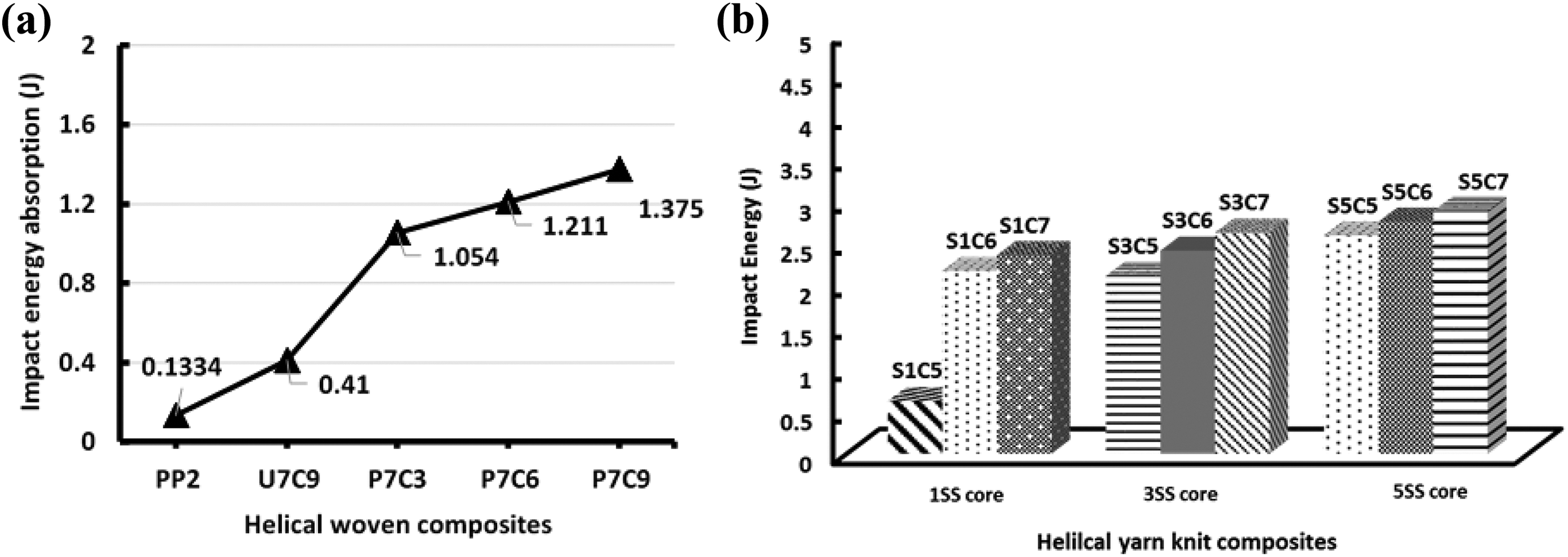
Impact energy absorption of woven and plain knit composites. (a) woven helical yarn composites and (b) knitted helical yarn composites.
When the UD fabric (U7C9) is reinforced, the impact energy absorption of behaviour is increased to 0.41 J. The composite reinforced with woven helical yarn fabric exhibits improved absorption level of 1.054 J. In addition, increase in thread density increases the absorption level of composite (P7C9) to 1.375 J. This is due to the presence of increased number of fibres that enhances the absorption nature of composite. Similarly, the impact energy absorption behaviour of plain knit composites is shown in Figure 19(b). It is observed from Figure 19(b) that plain knit helical yarn–reinforced composite shows higher impact energy absorption compared to pure PP composite (0.133 J). The increase in wrapping density increases the impact energy absorption level of the composite (1.144–1.574 J). Similarly, the increase in core filaments also increases the impact energy absorption of composite (0.281–0.914 J). This is due to interlocking of resin and helical fibres resulting in increased energy absorption level. Compared to composite specimens of S5C (0.914 J) and SC7 (1.574 J), the higher impact energy of 2.789 J is observed for S5C7 specimen. This indicates that the composite having helical yarn structure with core yarn is highly suitable for impact resistance panels.
Conclusions
The carbon helical yarn was fabricated successfully in direct twisting machine with varying number of helical density and core filaments. The SEM images confirmed that resin penetrated well inside the fibre bundles showing good fibre wet out. In case of woven fabrics, increase in thread density increased the total loss of fabric. However, no improvement in S11 values was observed. This indicates that woven helical yarn fabric acts as a reflector to incident EM waves. The composite made from woven fabric shows entirely different shielding behaviour. The absorption coefficient of composite was lower (0.25) compared to woven fabric. Similarly, the shielding effectiveness of 1/1 plain knit fabrics and their composites was investigated in wale and course directions. The absorption coefficient was maximum for fabric having optimum number of core filaments for higher coiling density. In addition, increase in coiling density and core filaments increased the overall SE of plain knit fabric. The increase in fabric layers improved the absorption coefficients of fabrics for certain type of fabrics. However, the overall shielding effectiveness was higher for all the fabrics. In the composite form, absorption coefficient was lesser compared to plain knit fabrics. The knitted composite showed more reflecting shielding due to penetrated resin and disturbed helical structures. Hence, the fabric form can be used as EM absorbing structures and the composite form can be used as reflective shielding panels in C-band frequency region.
Footnotes
Declaration of Conflicting Interests
The author(s) declared no potential conflicts of interest with respect to the research, authorship, and/or publication of this article.
Funding
The author(s) received no financial support for the research, authorship, and/or publication of this article.