
Abstract
A micro-mechanical composite material model is developed to simulate the behavior of unidirectional composites under impact loading conditions in the nonlinear finite element solver (LS-DYNA®). The nonlinear strain rate and pressure dependency in the composite material model is accounted by the resin, which uses previously developed state variable viscoplastic equations. These equations have been originally developed for metals; however, these are modified to account for the significant contributions of hydrostatic stresses typically observed in polymers. The material model also uses a continuum damage mechanics (CDM) based failure model to incorporate the progressive post-failure behavior. A set of Weibull distribution functions are used to quantify this behavior, and a methodology of assigning physical significance to the choice of damage/softening parameters used in these functions is presented. The impact response of composite laminate plates has been simulated and compared to the experiments. It has been observed that the predicted results compare favorably to the experiments.
Keywords
Introduction
In the past few decades, laminated composites have become the most favored material system for a wide range of industrial applications. Factors such as potential for structural tailoring, superior strength and stiffness for a given weight along with higher toughness and mechanical damping, and so on, have justified their increased use. Due to this high usage, the behavior of laminated composites under impact remains a concern, mainly as impacts are unavoidable during manufacturing, day-to-day usage, and maintenance.
Predicting an accurate behavior of the laminated composite, especially for impacts which induce a significant amount of internal damage, is a significant challenge reported by Collombert et al. 1 and reviewed by Abrate. 2,3 With the advancements made in computing technology, finite element (FE) simulations have become a substantial tool to study impact problems, especially with the use of an accurate material model as detailed information on the spatial and temporal distribution of damage can be made available during impact. 4 The popular transient nonlinear FE code LS-DYNA has emerged as a powerful tool to carry out such analysis, as it offers a fast and simple user interface to implement own complex material models.
In numerous experiments over the years, many researchers have observed that the modulus and strength of the composites increases with strain rate. 5 –7 This dependency of a composite response on strain rate is important in impact simulations. 17 Furthermore, many experimental works 9 –12 have shown that composite sensitivity to strain rate is usually driven by the resin behavior. Hence, to accurately capture the response of a composite lamina, there is a need to accurately represent the nonlinear behavior of the polymer constituent.
Polymeric materials have been typically observed to exhibit nonlinear behavior beyond 1–2% strain. Traditionally, this behavior was typically represented with the use of viscoelastic material models. 13,14 However, the use of state variable-based viscoplastic material models, typically used for metals, has gained significant popularity 15,16 in the last two decades. Even though the deformation response in polymers is due to the nonlinear response of long chain molecules as opposed to the propagation of dislocations for metals, a similar unified inelastic strain variable approach can still be utilized with the state variables representing a different physical meaning. Pioneering work in developing numerical material models for polymers has been carried out by Goldberg over the years. 8,17
In comparison to metals, polymers in general exhibit a strong pressure-dependent behavior, 18 –20 which results in different yielding under uniaxial tension, compression, shear, and biaxial loadings. Furthermore, the assumption of volume constancy that typically holds in metals during plastification does not hold for thermoplastic polymers. This effect is particularly noticed in the tensile range (uniaxial and biaxial tensile stress states) and cannot be neglected. The reorientation of molecule chains and the presence of damages lead to anisotropic behavior of the polymers. The aforementioned characteristics make modeling polymers a challenge much less as a part of a micro-mechanics-based composite material model. A material model that encapsulates these behaviors of polymers has been initially proposed by Goldberg et al. 21 and further enhanced by Zheng and Binienda. 22
Capturing the failure modes accurately is another important aspect which enhances the complexity involved in the numerical modeling of composites. As observed from the work of Mayes and Hansen, 23 a wide range of failure modes are to be captured for the accurate representation of a composite material model. Typically, many researchers 4,24,25 have accomplished this using a macro-mechanical approach (where the composite material is modeled as an anisotropic, homogenous material), due to the simplicity and computational efficiency it offers. However, a more realistic and accurate way of doing this is using micro-failure criterion in a micro-mechanical approach (where a representative volume cell (RVC) composed of the fiber and matrix is used to represent the composite).
Typically, damage growth in a polymeric composite manifests itself in the form of strain softening of the material. Matzenmiller et al. 26 developed a continuum damage mechanics (CDM) based model which utilizes the Weibull damage functions to progressively damage the material, thereby introducing strain softening into the constitutive response. This model has been observed to improve the prediction of impact damage on composites significantly. 4,27 –30 However, these works use ad hoc softening parameter values in the Weibull functions to predict damage depending on the composite and the structure that is being analyzed, thereby lacking a proper way to characterize the composite material models.
The objective of the present work is to develop and enhance on the three-dimensional material model built by Tabiei and Aminjikarai
30
for predicting the impact response of unidirectional composites (UDC). As explained in the following sections, this is achieved by implementing strain rate sensitive and pressure-dependent constitutive relations (modified Bodner–Partom viscoplastic state variable model
22,31
) for the resin in a micro-mechanical-based RVC which utilizes isostrain boundary conditions and implementing a CDM-based progressive post-failure model and develop a methodology that assigns physical significance to the choice of damage/softening parameters.
Micro-mechanics of the UDC
The RVC used to develop the micro-mechanical relations is shown in Figure 1. This RVC is the same as the one originally proposed by Pecknold and Rahman
32
and further used in various micro-mechanical models in the literature
29,30,33
and in the work of Medikonda et al.
34
However, for completeness, a brief description of the RVC is provided here. The fibers are assumed to be of square cross section for computational efficiency; this is especially beneficial since a model implemented in an explicit FE code uses very small time steps to satisfy the stability criterion. The unit cell is divided into three subcells: one fiber subcell, denoted by
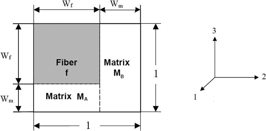
A representative volume cell of unidirectional fiber-reinforced polymer composite.

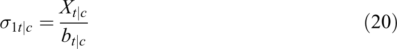
where Vf is the fiber volume fraction. As explained in detail in “RVC stress calculations” section below, effective stresses in the RVC are determined from the subcell values in two phases: first, stresses in fiber
Viscoplastic constitutive relations for matrix material
As discussed in the Introduction, the strain rate-dependent behavior of a polymer matrix composite is mainly attributed to the viscoplastic nature of the resin component. Hence, strain rate dependency is incorporated in the current model using the viscoplastic relationship developed by Goldberg et al. 21 and further enhanced by Zheng and Binenda. 22 It has to be noted that the model proposed by Goldberg et al. 21 is a modified form of the Bodner–Partom viscoplastic state variable model, originally developed for metals. For completeness, the modified viscoplastic relations are discussed briefly in this section. Further details about the relations can be found in the study by Goldberg et al. 21
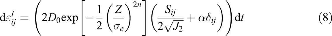
The total strain rate is assumed to be the sum of elastic and inelastic strain rates. The elastic strain rate is equal to the ratio of stress rate to Young’s modulus of the material, while the inelastic strain rate is a function of the deviatoric stress, Sij, the second invariant of the deviatoric stress tensor J2, and an isotropic state variable Z, representing the resistance to the molecular flow
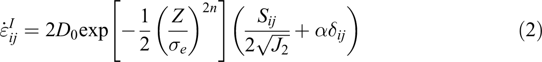
where D0 and n are the material constants representing the maximum inelastic strain rate and the rate dependence of the deformation response, respectively. The effective stress σe is defined as

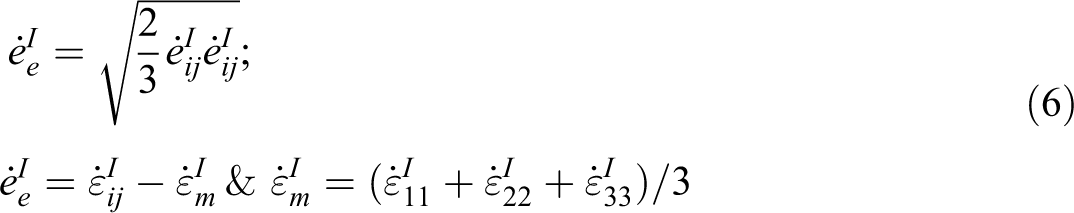
where α is the state variable controlling the level of hydrostatic stress effects and the two state variables (Z, α) are considered to be proportional to the effective deviatoric inelastic strain rate


The effective deviatoric inelastic strain rate,
It has to be noted that Z1 and α1 representing the maximum values of Z and α, respectively, are input as material constants along with their initial values Z0 and α0. In addition, q is a material constant representing the “hardening” rate.
One procedure for determining the resin material constants can be found in the original work of Goldberg et al. 21 ; alternatively, the material constants can also be determined by fitting the constitutive model to the experimental results using an error minimization scheme such as the least squares method.
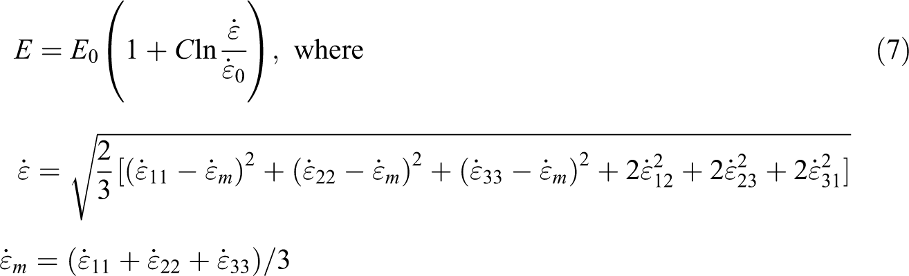
It is well known that the elastic modulus significantly increases with increasing strain rate in polymers and subsequently in polymer matrix composites. Zheng and Binenda, 22 drawing inspiration from the work of Yen, 27 have proposed the use of dynamic elastic moduli that account for the strain rate effect
Since there is no closed form solution for the first-order differential equations shown in equations (2) through (7), which formulate one differential equation per component, a numerical solution is obtained at each explicit FE time step.
The incremental forms of equations (2) and (4) to (6) are as shown below
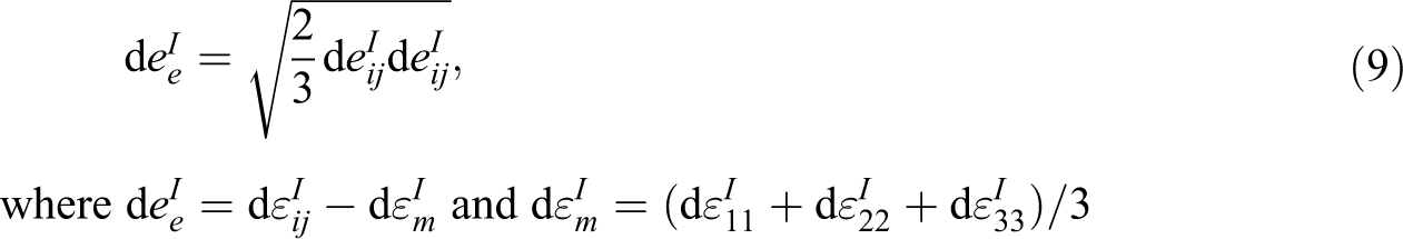


where the prefix “d” represents the respective incremental values and the inelastic strain increment is multiplied by the time step “dt.” It has to be noted that in an explicit FE code, at time step n + 1, the following values are available and are all used as input parameters for the matrix material stress response calculation: stress of the matrix material from the previous time step n,
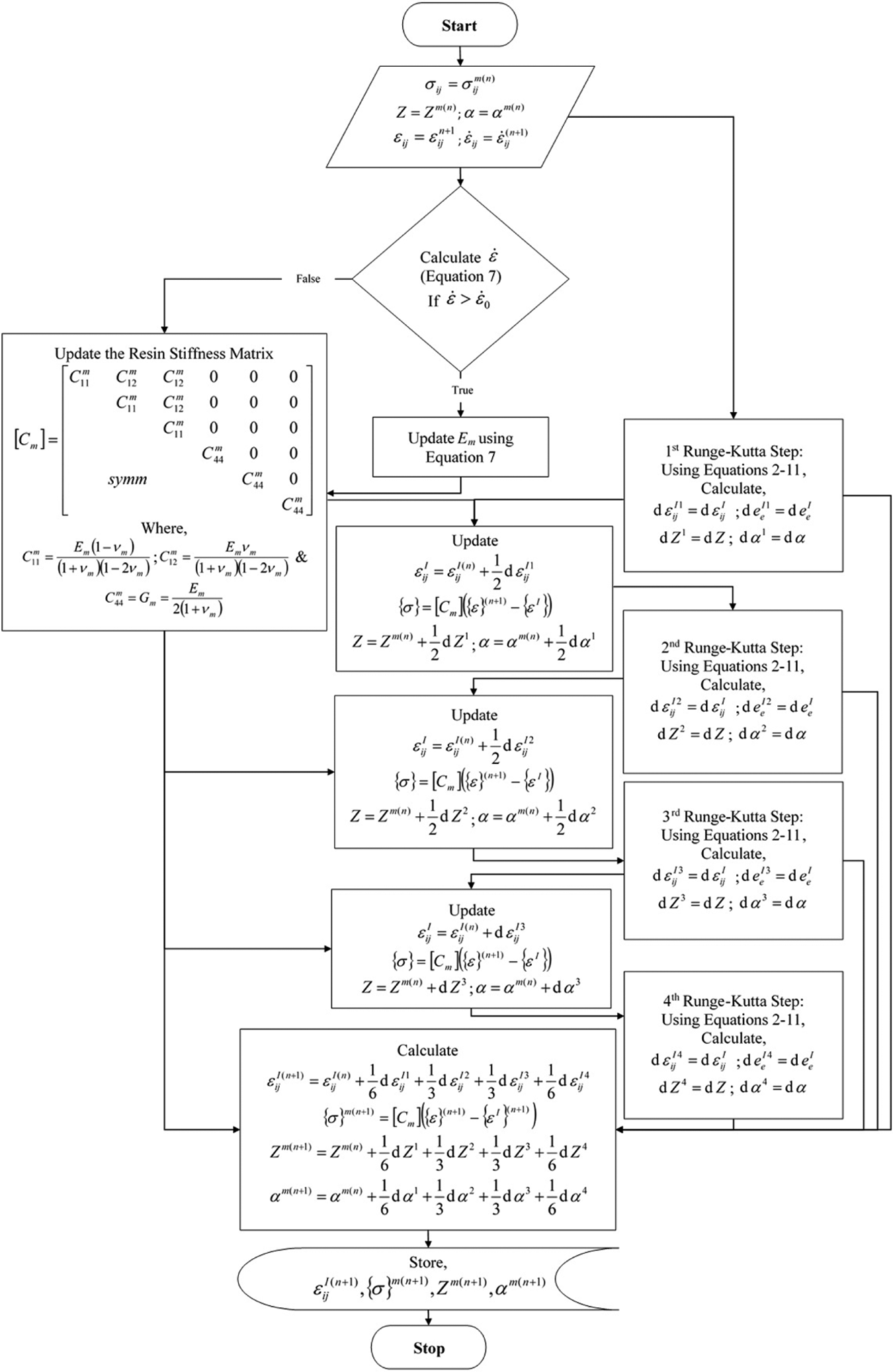
Illustration of a four-step Runge–Kutta method implemented for the resin material.
Constitutive relations of fibers
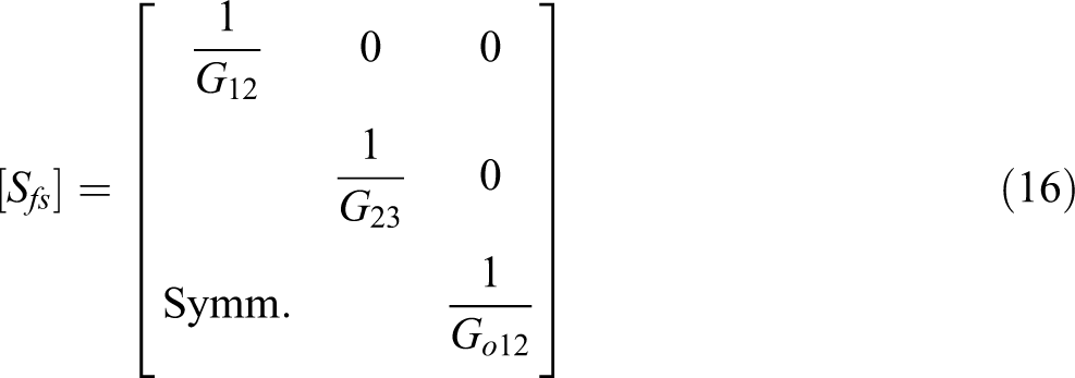
The fibers are considered to be linearly elastic materials which are initially transversely isotropic but become orthotropic with damage evolution. Damages to the fibers are assumed to be a result of only the direct stresses and the shear stresses do not contribute here. This causes the damages to be oriented in the material directions of the fibers and act independently. The constitutive relations of the fibers can be written in matrix form as

where
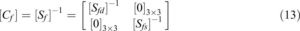
The direct stress compliance matrix, whose inverse is the direct stress stiffness matrix, should be symmetric and the following relationship should be obeyed

The direct and shear stress compliance matrices in terms of the properties of the fibers are
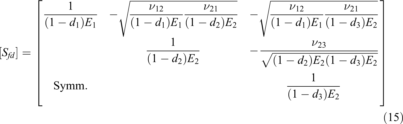
where E1 and E2 are the longitudinal and transverse moduli of the fibers, respectively; νij,

where aG is a material constant which expresses the strain rate sensitivity of
Damage evolution in constituents
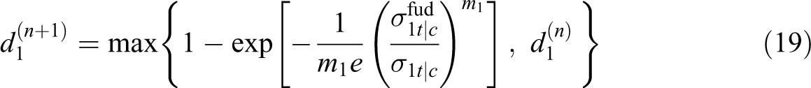
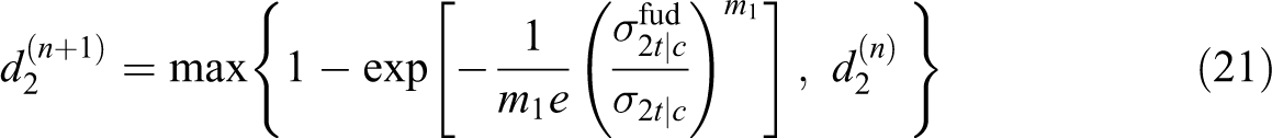
Preserving the thermodynamic constraints in damage mechanics, damage is considered an irreversible process and has been implemented as such in the current model. In their work, Matzenmiller et al. 26 proposed an approach which used a Weibull distribution function to describe the damage evolution as a function of strain over the entire load range. Depending on the failure mode considered, a slightly modified version of this model is used here. The evolution function for damage describing fiber breakage at time step n + 1 is expressed as follows
where
where
In the transverse directions, the damage evolution functions (equations (21) and (22)) are considered to independent of the strain rate. The properties of the fibers in both transverse directions are the same; therefore, the evolution functions as well as their parameters are the same and only the history of the loading is different.

The damages in transverse directions of the fibers are constrained to not exceed 0.10.
Damages are imposed on the matrix material, but they affect only the shear stresses of the resin, which is considered to be the main contributor to the shear stresses of the RVC. A single Weibull distribution function is accepted again as an evolution function of the damages but it involves the ultimate strain for the damage development rather than the ultimate stress. The damage evolution function for in-plane shear is as follows

The damage evolution functions for the matrix material in the out of plane directions for a time step n + 1 are calculated as follows


The damages of the matrix material are constrained to not exceed 0.20. These damages are applied on the matrix material shear stresses when the stress response of the subcells is calculated. It has to be noted that damages for the matrix material are being applied on the stresses unlike what was done for the fibers, where the elastic moduli were reduced. The reason for this is considered to be two-fold; one is because the matrix material model is assumed to be isotropic while the damages in the material are not and secondly, the viscoplastic material model calculates the actual stresses of the material and not the effective stresses of the damaged material. 30,35 Lastly, the primary reason for constraining the damages is to account for the numerical instabilities that arise when stress in an element goes to zero.
Delamination
Delamination is a failure mode often considered to be a consequence of the quadratic interaction between the out-of-plane stresses of a lamina and is assumed to be mainly a lamina failure. The loading criterion for this failure mode has the following form

Here, E3 is the normal tensile modulus of the lamina,

where φ is the Coulomb’s friction angle. The normal tensile and the out-of-plane shear moduli of the lamina are computed at the first time step and stored as a material property.

where r is the damage threshold as given in equation (26) and md is the damage exponent for delamination. Delamination damage is constrained at 0.10 to avoid numerical difficulties, and when this maximum value is reached in an element, it is considered to be fully delaminated.
When delamination failure given by equation (26) occurs in an element, depending on the opening or closing of the damage surface, the damages variables (


For tensile mode, all the through-the-thickness stress components
RVC stress calculations
The effective stresses in the RVC are determined from the subcell values in two phases: first, stresses in the fiber
In the homogenization process, isostrain boundary conditions are assumed for all the three subcells of the RVC, which implies that the rule of mixture is applied for the stress calculations. In a physical sense, this means that the fiber and matrix materials act in parallel in all directions under loading, which isn’t quite realistic. 34 However, this assumption is made in order to simplify the micro-mechanical relations.
The direct stresses of part


The assumption of isostrain boundary conditions in all directions mainly poses problems in accurately estimating the shear behavior. Now it is well known that the behavior of UDCs under shear is dominated by the behavior of the matrix material. Hence, in order to accurately represent this, ad hoc volume fraction coefficients are implemented for shear and a rule of mixture involving them is applied. Then, the shear stress in part


The different shear volume fraction coefficients, Vs 4 and Vs 5, for the in-plane and transverse shear have values quite lower than the volume fraction of the fibers. Since the matrix material is modeled as viscoplastic and the fibers are modeled as elastic, after the saturation of the plasticity in the matrix material (shear directions), the fibers tend to absorb the load and assume the role of strain hardening.
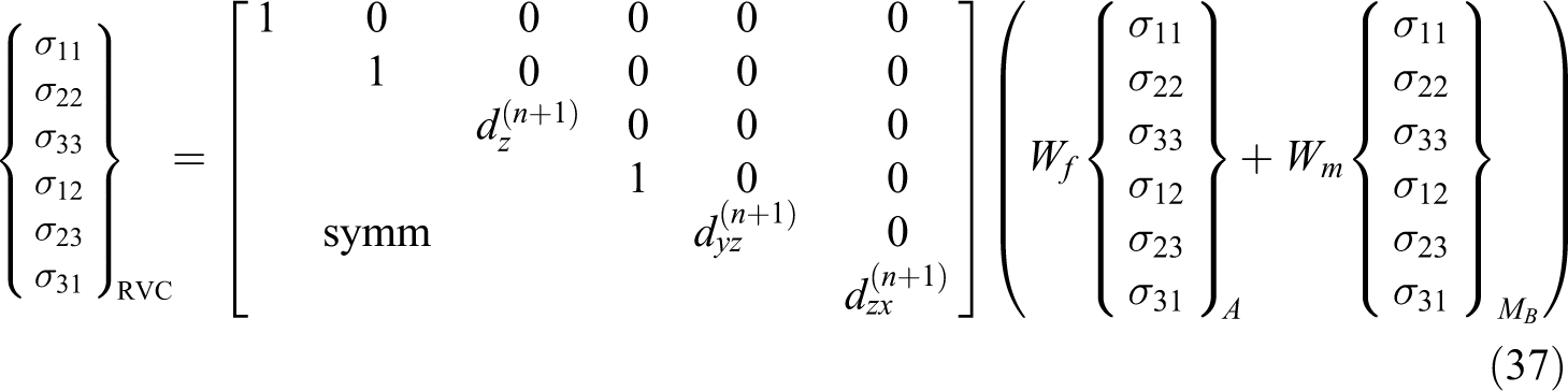
Finally, the effective stresses in the RVC are obtained by applying the rule of mixtures again which yields the following relations including the softening of through-the-thickness components due to delamination failure as follows
The total stresses of the fiber, the internal state variables along with the total stresses of the matrix material, and the progressive damage variables are stored as history variables at each time step of the explicit time integration process for the next time step calculations.
Damage parameter estimation
The damage parameter that has been used in the Weibull functions above (equations (19), (21), (22), etc.) has been observed to be very problem dependent and difficult to characterize. A small value of the damage exponent (e.g. m1 in equation (19)) makes the material behave in a very ductile manner and the behavior becomes increasingly brittle as this value increases. Hence, it is difficult to obtain the softening response of most quasi-brittle materials. The softening response heavily depends on the setup and test machines, which can lead to very different results. The choice of damage parameters for each mode has been debated by Williams and Vaziri 4 and Tabiei and Aminjikarai. 30 A procedure for the calculation of softening parameter used in the damage evolution function has been presented in the current study.
In order to avoid undesirable localization, Bazant and Oh 36 proposed the crack band theory. According to this theory, regardless of the choice of mesh, the overall energy dissipation due to damage must remain constant. This concept was further used by Pinho et al. 37 and subsequently Cousigné et al., 38 who have discussed a smeared formulation involving damage variables, where a length parameter has been introduced into the damage constitutive law. Their work primarily relies on the calculation of failure strain based on the fracture toughness, which is subsequently used to calculate the damage in the composite. This calculation of a failure strain is of little consequence to the damage function discussed in the current work. Hence, a numerical algorithm which iteratively solves for the softening parameter has been presented.
The total energy absorbed by one element after failure can be expressed as

where
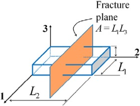
Fracture plane for a load. 38

Equations (38) and (39) can be equated and the energy dissipated per unit volume absorbed by an element is given by the following relation

where l is the characteristic element length. For square elements, it is expressed in terms of the area at the integration point by the following relation 38

Since the fracture toughness Γ is a constant known value for a particular material, we can solve for the softening parameter mf numerically as
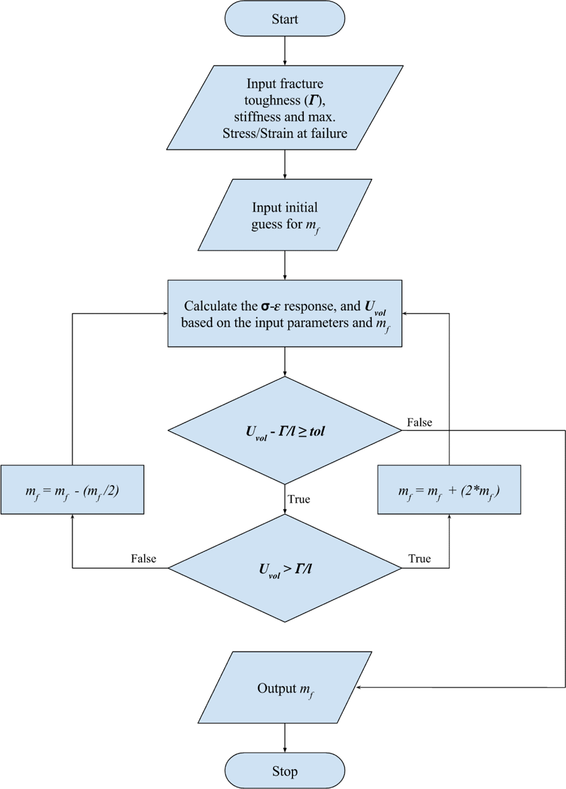
Flowchart demonstrating the calculation of the damage parameters.
It has to be noted that once the softening parameter mf has been calculated for a certain
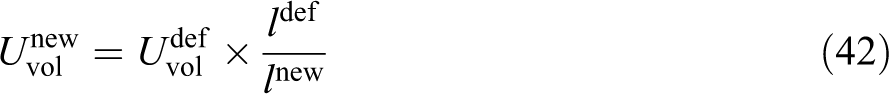
The validity of the subroutine has been first verified by implementing it in MATLAB® for a T300/913 composite laminate and different element sizes ranging from 0.25 mm to 4 mm. The necessary initial inputs are
Figure 5 illustrates that the algorithm calculates different damage parameters for different element sizes. It has to be noted that the damage exponent increases with increasing element length. The corresponding stress versus strain response has been illustrated in Figure 6.
Calculated damage versus strain.
Lastly, validity of the whole procedure can be verified by back calculating the fracture toughness for each element size. This can be done by measuring the area under each curve in Figure 6 and multiplying it with the corresponding element length. Figure 7 demonstrates that a constant value of fracture toughness that has been input into the subroutine is reproduced for every element length considered, that is,
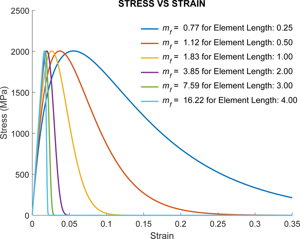
Stress versus strain response for the different damages computed.
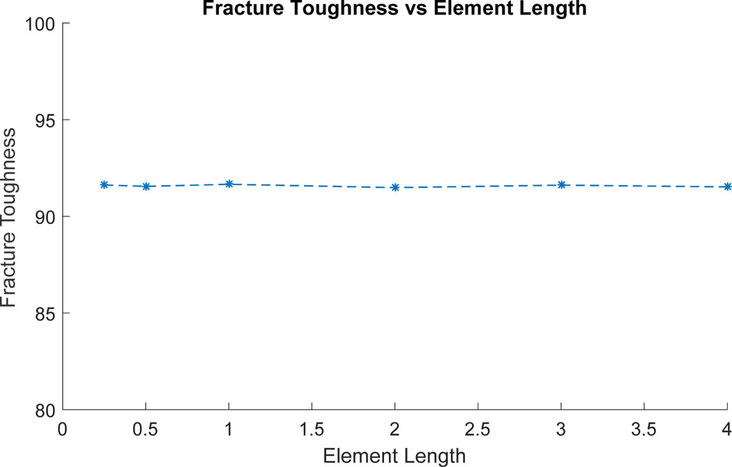
Corresponding fracture toughness back calculated.
The damage exponent is calculated individually for each element inside the mesh and this can be quite taxing for large-scale problems. As it can be observed in the flowchart presented in Figure 4, the algorithm draws inspiration from the bisection method and thus determines the damage parameter rather quickly. The speed at which the damage parameter is determined is further illustrated in Figure 8, for an input/target fracture toughness of 21.7 MPa mm and an initial guess of 2 for the damage exponent. The solution converges in just nine iterations. Of course, it has to be noted that the speed of the solution is slightly influenced by the initial guess provided to the subroutine.
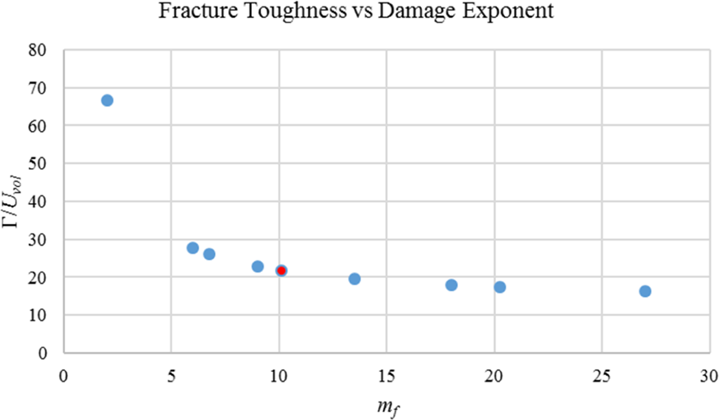
Fracture toughness versus damage exponent for an element with characteristic length = 1.
Results and discussion
Impact on a 10-ply E-glass/epoxy laminate
In the current section, impact loading on E-glass/epoxy laminate plates has been simulated using the composite material model discussed so far. The experiments have been carried out in a drop-weight setup by Collombet et al.
1
The plates are circular with a diameter of 200 mm and a thickness of 1.8 mm. They are put together by stacking 10 unidirectional plies in one of the three configurations
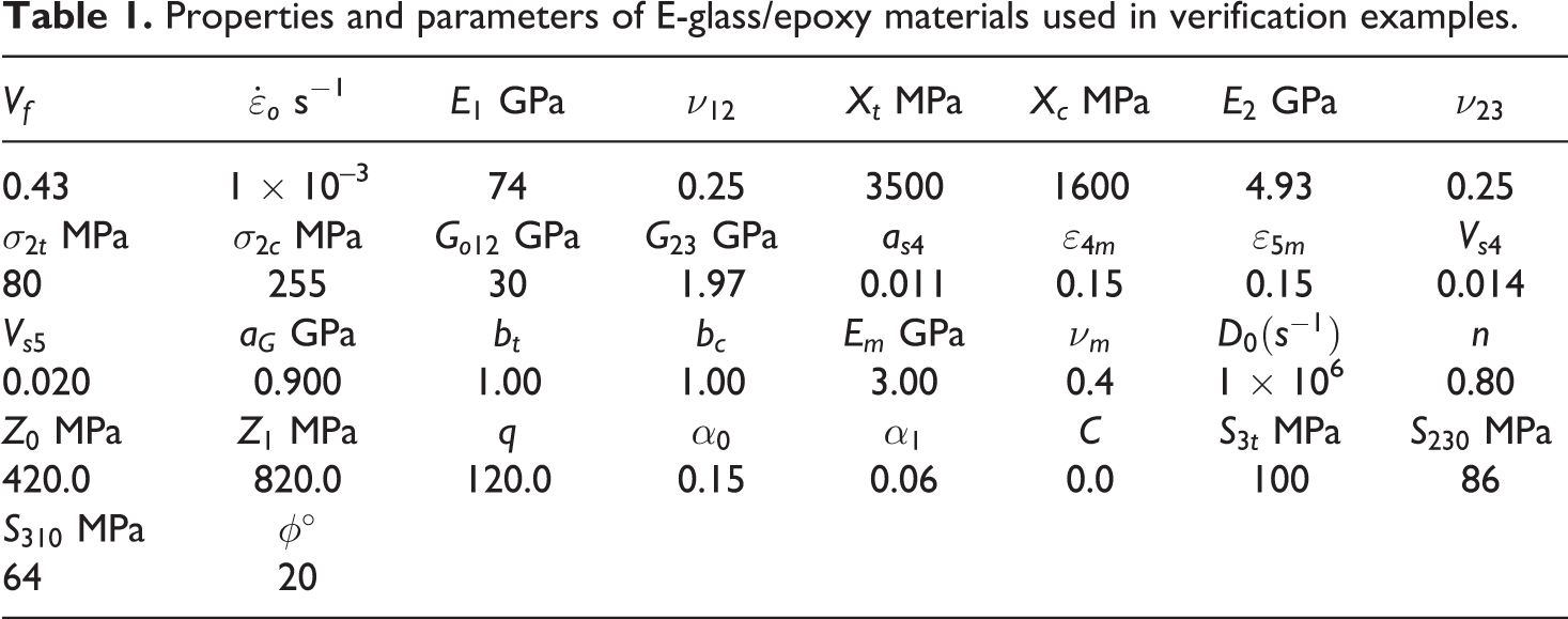
The FE models used in the simulations are shown in Figure 9. As seen is these figures, only a quarter of the experimental setup is modeled due to symmetry, and this helps reduce the computational effort. In addition, simulations are carried out for a coarse mesh (Figure 9(a)) and a fine mesh (Figure 9(b)). As seen in Figure 9(c), each lamina is modeled using a single layer of solid elements. The support on which the laminate rests is completely constrained at the bottom and is modeled as a rigid material. The ring is constrained from moving in the vertical Z-direction to account for the pressure applied on it, and this replicates the uniform pressure applied on the springs. 1 Lastly, the impactor is modeled as a rigid material as well and only the contact surface of the hemispherical end is modeled using shell elements. Eroding surface-to-surface contact is defined between the impactor and the plates, while automatic surface-to-surface contact is defined between the support, the ring, and the plates. The constituent properties and parameters used in the simulations are given in Table 1. It has to noted that some of the required material parameters which are not available in the study by Collombet et al. 1 have either been obtained from the literature 17,22,30,35 or valid estimates have been used. For example, the parameters required for the viscoplastic constitutive relations of the epoxy resin are not available directly in the literature and neither are their uniaxial and shear responses at different strain rates from which they can be determined. Hence, the parameters of the epoxy used are based on the values provided for the E-862 resin 22 which shares similar elastic properties with the epoxy resin.
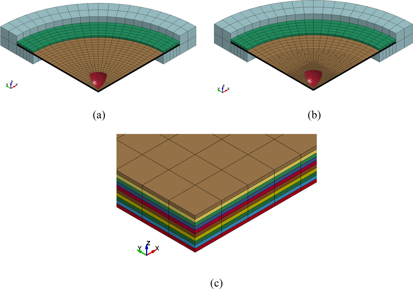
FE model used for FE simulation of a 27 J impact on
Properties and parameters of E-glass/epoxy materials used in verification examples.
Rate sensitivity of the composite material is predominantly accounted by the resin in the proposed material model. In the parametric studies carried out by Zheng, 39 it has been observed that Z1 and α1 have a significant effect on the strain rate. Increasing value of Z1 and decreasing value of α1(in tension) tend to increase the maximum/yield stress. Parameters Z0 and α0 on the other hand have been observed to control the starting point of the nonlinearity.
Ad hoc volume fractions control the effect that the resin behavior has on the overall composite which in turn effects its rate-dependent behavior in shear. However, this is subjective and has to be determined experimentally depending on the stress–strain responses of the composite and its constituents. In general, small changes in the ad hoc volume fraction parameters will not have a great influence on the answer.
It is important to note that the criterion for element erosion (fiber breakage), discussed in “Damage evolution in constituents” section, has been deactivated for the cases studied. Mainly because of the experimental reference paper by Collombet et al., 1 there was no reference to any fiber breakage.
Figures 10 –12 show the contact force versus time history for all three-laminates simulated along with the experimental results. It must be noted that the contact force obtained from the simulations has been multiplied by a factor of four since only a quarter of the model has been subjected to impact. Based on the observed results, it can be said that the effect of the mesh sizes considered has been minimum.
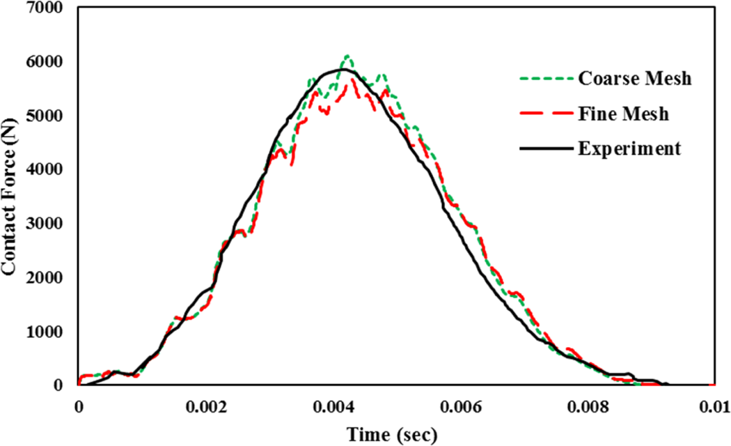
Contact force–time history predicted by the current model for a 27 J impact on a
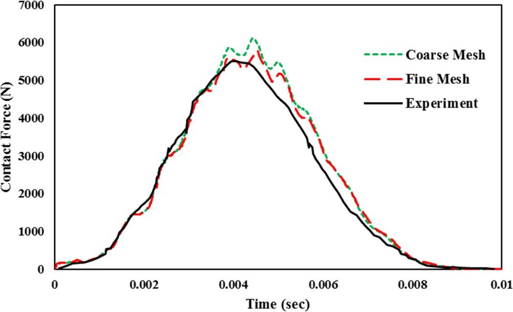
Contact force–time history predicted by the current model for a 27 J impact on a
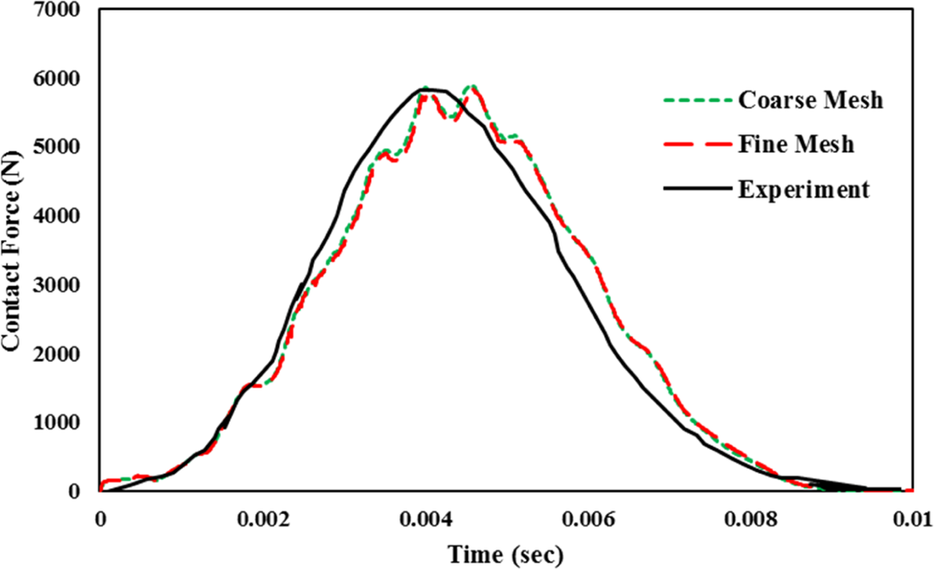
Contact force–time history predicted by the current model for a 27 J impact on a
The peak contact forces obtained for
Effect of hydrostatic stresses on impact problems
As discussed in the “Introduction” section, hydrostatic stresses have been observed to have a significant contribution to the response of a polymer. In the current model, hydrostatic stress effects are accounted through the inclusion of a state variable “α”, and this can be turned off by setting
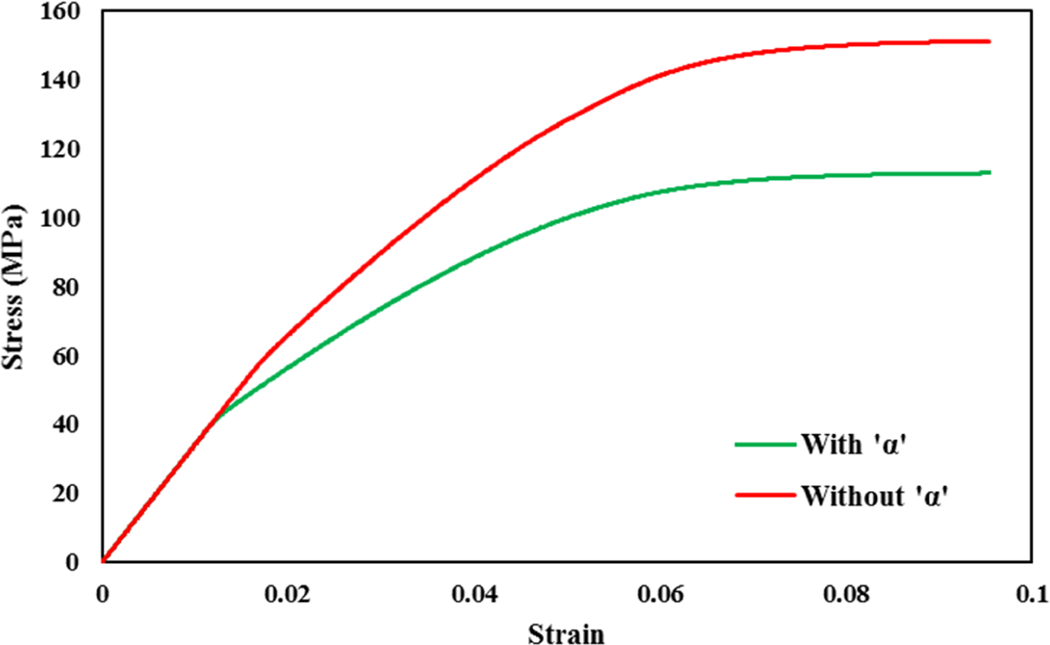
Comparing the stress response of the epoxy resin with and without the inclusion of the hydrostatic stresses (“α”) for a strain rate of 1.0/s.
In this section, the importance of having hydrostatic stresses in analyzing the impact response has been further investigated. In order to do this, the fine mesh models discussed in the previous section have been simulated with and without the inclusion of “α” and the results have been presented in Figures 14 to 16.
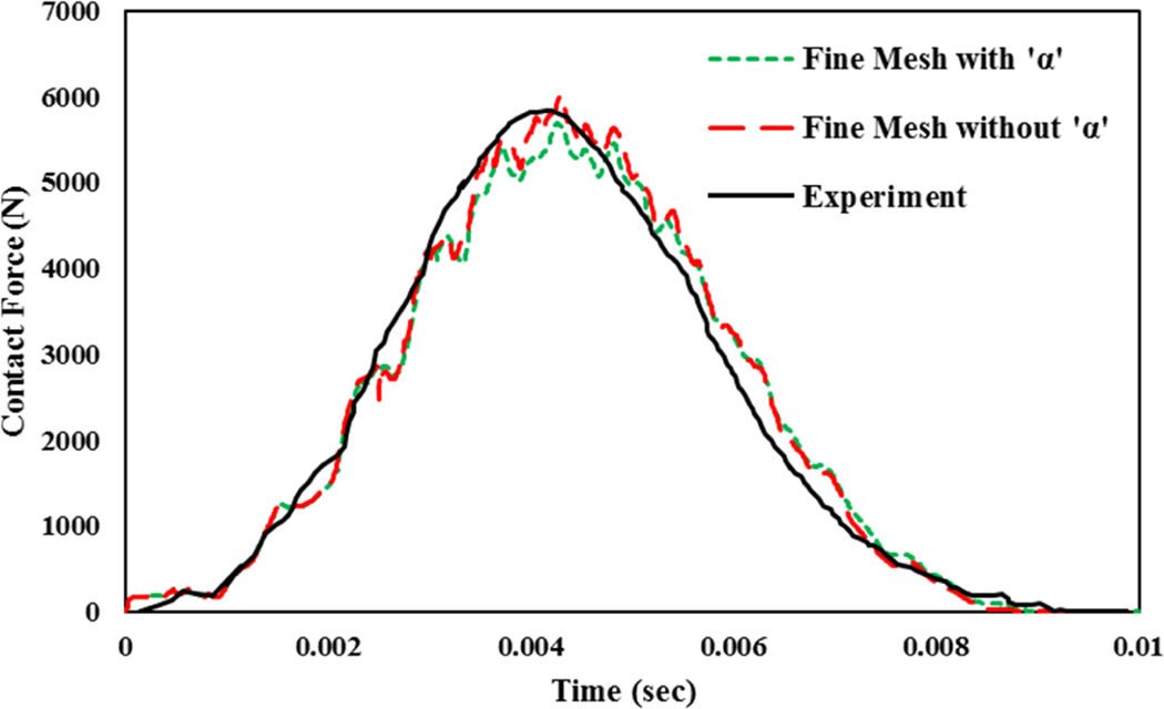
Contact force–time history predicted by the current model for a 27 J impact on a
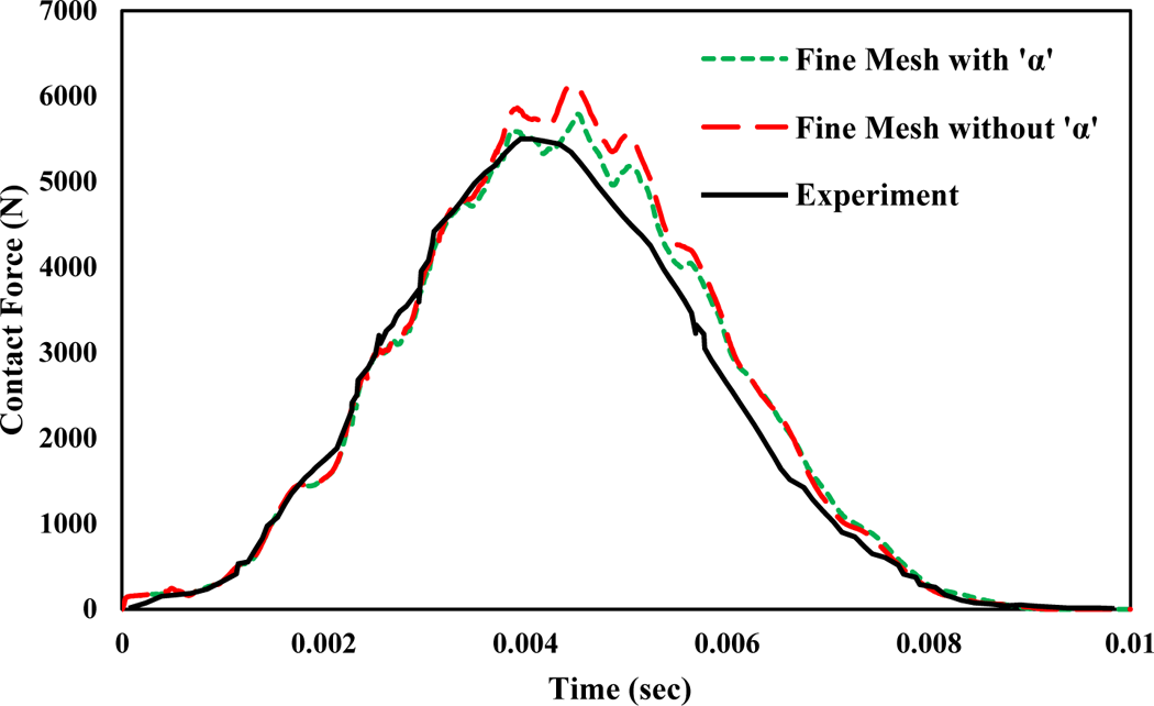
Contact force–time history predicted by the current model for a 27 J impact on a
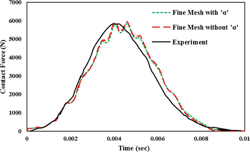
Contact force–time history predicted by the current model for a 27 J impact on a
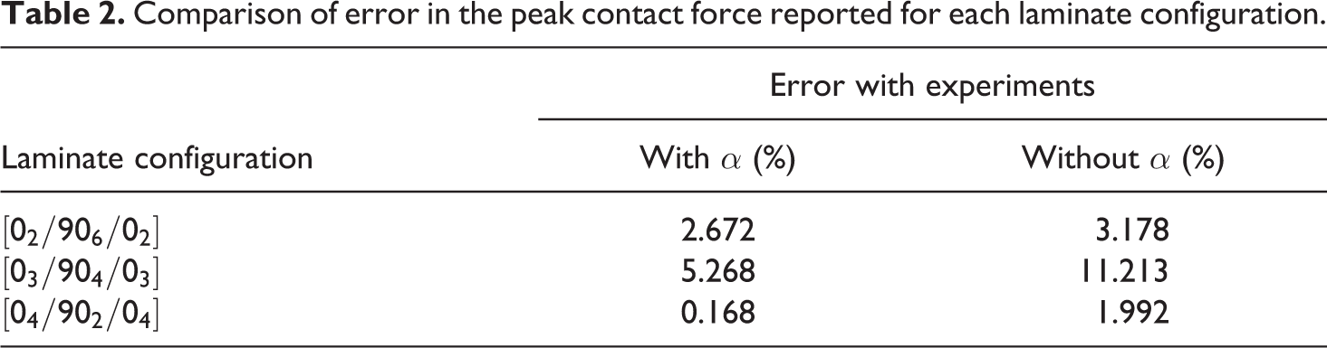
Based on these results, it can be said that the peak contact force predicted by the simulations with the inclusion of hydrostatic stress effects is closer to the experimental values. The exact amount of error for each case is reported in Table 2 and the maximum error has been reported in the simulations of
Comparison of error in the peak contact force reported for each laminate configuration.
Impact event on a 22-ply E-glass/epoxy laminate
In order to better understand the hydrostatic stress effects, impact events have also been carried out on a much thicker E-glass/epoxy plate. The FE model used in the simulations is shown in Figure 17. Once again, in order to reduce the computational effort, only a quarter of the laminate is modeled due to symmetry and each lamina is modeled using a single layer of solid elements. The model consists of 22 unidirectional plies with a stacking sequence of
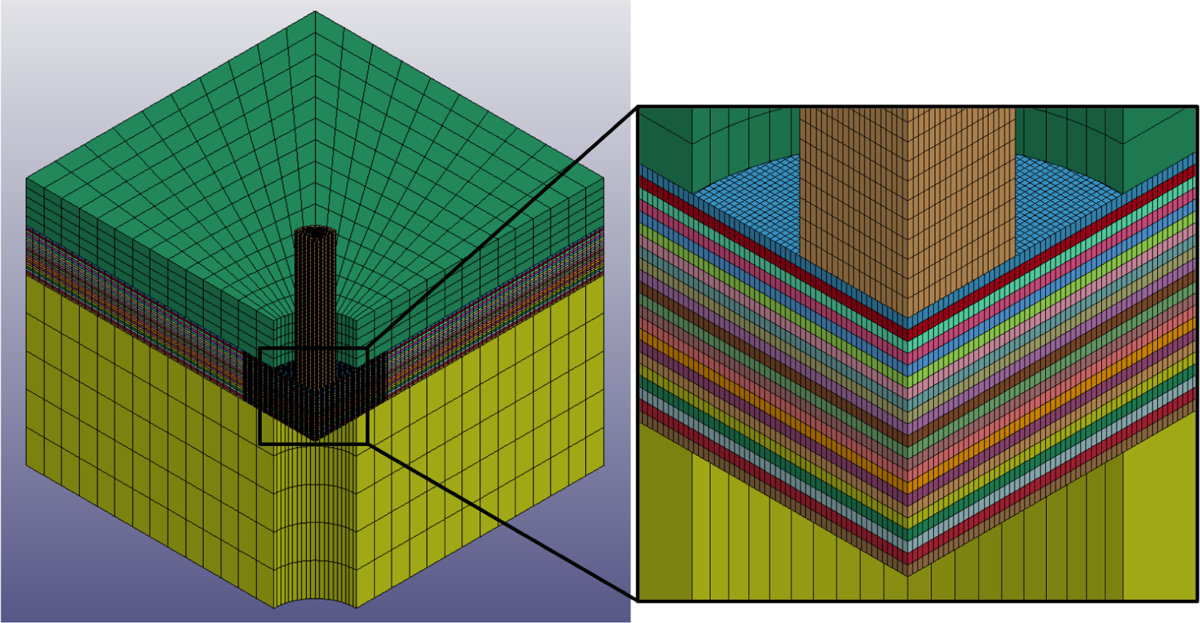
Full model and close-up view of the FE model used for simulation of impact on a thick plate.
Unlike the low-velocity boundary condition used in the earlier case, the impactor in the current case is being displaced by 10 mm (in the downward direction) to observe the response of the plate at a higher state of deformation. Simulations have been carried out with and without the inclusion of “α” to compare the effect of hydrostatic stress in predicting the contact force and the results have been presented in Figure 18. It has to be noted that due to the lack of experimental data, only the numerical results have been compared in this figure.
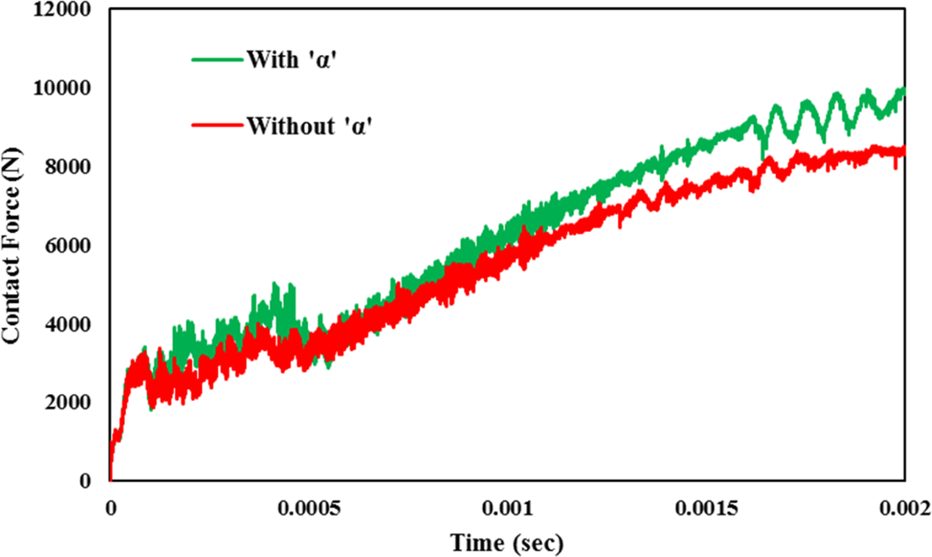
Contact force–time history predicted by the thick plate model on a
Results presented in Figure 18 show that at higher states of deformation, the contribution resulting from the inclusion of “α” shows a significant effect on the contact force. For the current case, the simulation with “α” predicts a peak force of approximately 9981 N, whereas the case without “α” predicts a value of approximately 8518 N.
Conclusions
A micro-mechanics based material model is implemented into an explicit dynamic FE code LS-DYNA and is used for simulating the behavior of composite structures under impact loading. The model assumes an RVC and the effective stresses of the unit cell are calculated based on the isostrain boundary conditions between the fiber and resin subcells. The nonlinear behavior of the resin is accounted with the help of a viscoplastic state variable model proposed by Goldberg et al. 21 and Zheng and Binenda. 22 This model represents both the strain rate dependency and the pressure dependency usually encountered in polymeric materials.
Progressive post-failure behavior is modeled using a CDM-based damage model. Different Weibull damage functions are used for various failure modes such as fiber failure, matrix cracking, and delamination, and the response of the composite is softened depending on the failure mode. The problem of determining the damage/softening exponents in the damage functions has been addressed using a fast iterative algorithm from within the constitutive model itself. The procedure discussed in this algorithm assigns physical significance to these exponents and even accounts for the strain localization typically observed in FE models.
All of the above discussed characteristics of the micro-mechanical model make it unique and very suitable for impact simulations, validation of which is presented in the current study for impact on E-glass/epoxy laminates with different configurations. Contact force–time histories predicted by the model are found to agree very well with experimental results. In addition, the effect of hydrostatic stresses on the peak impact force is studied in detail, and the inclusion of this characteristic of the polymer has been observed to aid in predicting more accurate results, thereby establishing its significance.
Footnotes
Declaration of Conflicting Interests
The author(s) declared no potential conflicts of interest with respect to the research, authorship, and/or publication of this article.
Funding
The author(s) received no financial support for the research, authorship, and/or publication of this article.