
Abstract
Electrically conducting polyaniline/multiwalled carbon nanotubes (PANi/MWCNTs) nanocomposites were successfully synthesized via chemical oxidative polymerization. For this purpose, PANi was first prepared in an aqueous acidic medium, hydrochloric acid (HCl), at various temperatures to determine the proper polymerization temperature and to prepare the polymer with the highest electrical conductivity. For nanocomposite preparation, the polymerization of aniline (ANi) was carried out in the presence of various amounts of MWCNTs dispersed using a proper surfactant. The effect of HCl and MWCNT contents on the conductivity of the resultant composites was investigated. The results showed that the conductivity was monotonically increased with increasing the MWCNT and HCl levels. In addition, the effect of anionic and cationic surfactant type, sodium dodecyl sulfate (SDS) and cetyltrimethylammonium bromide (CTAB), on the conductivity and morphology of the resulting nanocomposites, was studied. Fourier transform infrared (FT-IR) spectroscopy, Raman spectroscopy, two- and four-point resistivity measuring methods, and field emission scanning electron microscopy (FESEM) were used to characterize the neat PANi and PANi/MWCNT nanocomposites. The conductivity variation of the conducting polymers versus elapsed time was investigated to determine the intensity and dominant aging mechanism. Electromagnetic shielding properties of the conducting nanocomposites were also studied. The results indicated that the nanocomposite with the highest MWCNTs level absorbed more than 83% of the incident electromagnetic waves.
Introduction
Recently, conducting nanoparticles of copper, silver, 1,2 gold, 3 graphite, 4 and carbon nanotubes (CNTs) 5,6 have been extensively used to enhance the electrical properties of insulating or semiconducting polymeric matrices. However, the use of expensive conducting nanoparticles increases the cost of final products and may deteriorate some other desired properties of polymeric matrices, that is, flexibility and uniformity. 7 Intrinsically conducting polymers (ICPs), such as polyaniline (PANi), polypyrrole (PPy), and polythiophene (PT), have attracted the interest of scientists and industry because of their high electrical conductivity and good environmental stability. 8 Nonetheless, conducting polymers often suffer from poor mechanical properties and environmental stability which prevent their widespread applications. Incorporating a small amount of CNTs or graphene in polymers can considerably improve their mechanical, thermal, and electrical properties of resulting nanocomposites. 9,10 Conducting polymers and their composites with nanoparticles are mainly used to manufacture semiconductors, 11 sensors, 12 aerospace parts, 13 electromagnetic shielding materials, 14 –16 membranes, and lightweight batteries. 17,18 Iijima 19 discovered CNTs as potential nanoparticles to be used in advanced and high technological materials due to their extraordinary electrical and mechanical properties. 20,21 To take advantage of optimal properties of nanocomposites, a proper dispersion of CNTs in polymeric matrices is essential. 22 Different methods, such as solution mixing, melt processing, solgel method, and in situ polymerization, have been used to disperse CNTs in the polymeric matrices. 23 –25 Although the solution mixing is the simplest preparation method, the insolubility of some crystalline polymers in solvents limits its application. The main advantage of in situ polymerization is the possible molecular bonding of polymer chains on CNTs which may lead to effective dispersion of the nanotubes inside polymer matrix. In addition, in situ polymerization is often used to prepare nanocomposites with insoluble or thermally stable polymers. 26
PANi as an intrinsically electrically conducting polymer prepared via miniemulsion polymerization 27 and electrochemical synthesis 28 is a good candidate for preparation of advanced conducting composites. 29,30 Downs et al. prepared electrically conducting PANi/CNT nanocomposites via in situ chemical oxidative polymerization. 31 The electrical properties of PANi can be adjusted by changing various parameters, such as aniline (ANi)/oxidant ratio, 32,33 polymerization temperature and time, 34,35 pH, 36 oxidizing agent type and concentration, 37 and selected protonic acid. 38 The main challenge for the preparation of PANi/CNTs composites is uniform dispersion of CNTs within polymer matrix to prevent formation of aggregates. In situ polymerization of ANi in the presence of surfactants seems to be an effective method to properly disperse CNTs in the polymer. 39 Among various applications of electrically conducting polymeric nanocomposites, microwave absorbers are of great importance because of elimination of electromagnetic wave damages. 40,41 Recently, electromagnetic interference (EMI) shields have been extensively used in the frequency range of 1–20 GHz due to rapid development of gigahertz (GHz) electronic 42 –44 and telecommunication systems. 45 Håkansson et al. investigated the electromagnetic shielding properties of PPy/polyester composites in the frequency range of 1–18 GHz. They found that the total shielding efficiency of the conducting composites is a function of polymerization time so that the efficiency exceeded 80% at the longer polymerization times. 44 Wang et al. studied microwave absorption properties of epoxy/multiwalled carbon nanotubes (MWCNTs) composites in a frequency range of 2–20 GHz. Their results indicated that the absorption efficiency is strongly dependent on the MWCNTs loading in the resultant nanocomposites. In addition, a microwave absorption ratio of 20–26% was obtained for MWCNTs loadings in the range of 8–10 wt%. 45 Makeiff et al. studied the conductivity and shielding properties of PANi/MWCNTs doped with para-toluene sulfonic acid in X-band range, that is, 8.2–12.4 GHz. 46 Philip et al. used oxidized MWCNTs, which were functionalized with p-phenylenediamine to prepare PANi/MWCNT nanocomposites with a higher electrical conductivity close to 10−1 S cm−1. 47 Ram et al. investigated the electrical conductivity of PANi salt synthesized by emulsion polymerization. 48 Microwave shielding properties of highly conducting PANi/MWCNT nanocomposites in the Ku-band range of 12.4–18.0 GHz were investigated. 49 Ting et al. blended PANi/MWNTs composite with an epoxy resin to prepare a microwave absorber. The microwave absorbing properties of the resulting epoxy blends were evaluated by measuring complex permittivity (ε′), complex permeability (μ′), and reflection loss in the frequency ranges of 2–18 and 18–40 GHz. 50 Yuping et al. measured the electrical conductivity and electromagnetic shielding effectiveness (SE) of conducting blends made of silicone rubber and different levels of HCl-doped PANi in the low frequency range of 3–1500 MHz. 51 Their results showed that the SE of the blends increased while their volume resistivity decreased with increasing HCl-doped PANi loading in the silicon rubber. Moreover, the SE of the resultant blends varied from 16 dB to 19.3 dB with increasing the HCl-doped PANi mass ratio.
Despite some research works done on the conductivity of PANi specimen with different MWCNTs levels, less attention has been paid on the aging behavior and electromagnetic interference (EMI) shielding properties of single-walled carbon nanotubes (SWCNTs)-reinforced conducting polymers. For this purpose, the effect of several polymerization parameters was firstly investigated to obtain proper conditions for preparation of the PANi and its nanocomposites with the highest electrical conductivity. Thereafter, the effect of polymerization conditions on the physical/chemical aging behavior of neat PANi and its composites with various MWCNTs levels was studied to determine the aging mechanism of PANi in the presence of the CNTs. The EMI shielding properties, that is, dielectric constant, dielectric loss, absorption, and reflection losses, and SE of the PANi and its nanocomposites containing various MWCNT levels, were investigated.
Experimental
Materials
All chemical reagents were purchased from Merck Co. (Darmstadt, Germany), unless otherwise stated. The ANi was distilled under vacuum to remove the trace of inhibitor and then stored at 5°C before use. Ammonium peroxydisulfate (APS) as oxidant, hydrochloric acid (HCl), and sulfuric acid (H2SO4) as dopants were used without any further purification. The MWCNTs (ArkNano, Shanghai, China) with an average length of 30 µm and an average diameter of 50–70 nm were used as conducting nanofibers. Sodium dodecyl sulfate (SDS) and cetyltrimethylammonium bromide (CTAB) were used as dispersing agents. Deionized distilled water (DDI) was prepared in our laboratory.
The PANi preparation
The PANi was synthesized at different temperatures in an aqueous solution using different dopants, such as HCl and H2SO4. The standard procedure for the polymerization of ANi was reported previously. 52 The recipes and experimental conditions for PANi preparation are summarized in Table 1. In a typical experiment, ANi hydrochloride (0.02 mol) and APS (0.025 mol) were dissolved separately in 50 ml DDI in a volumetric flask. The resulting solutions were stored at room temperature for 1 h and then mixed together for 24 h. The precipitate was filtered and washed with 0.2 M HCl and acetone. Finally, the product was dried in a vacuum oven at 60°C for 4 h.
Polymerization of ANi in the acidic media at different temperatures.
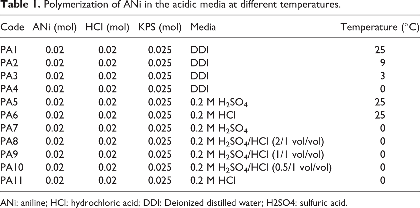
ANi: aniline; HCl: hydrochloric acid; DDI: Deionized distilled water; H2SO4: sulfuric acid.
Preparation of PANi/MWCNT nanocomposites
The PANi/MWCNT nanocomposites were prepared using SDS and CTAB as surfactants (Table 2). Typically, ANi hydrochloride (0.02 mol) was dissolved in 10 ml HCl (0.2 M) in a volumetric flask. In a separate flask, APS (0.025 mol) was dissolved in 50 ml of HCl (0.2 M). Additionally, MWCNTs were dispersed in 40 ml of HCl (0.2 M) by an ultrasonic homogenizer (Bandelin, Germany) using certain amounts of SDS or CTAB. The resulting dispersion was stored at room temperature for 1 h and then mixed with APS and ANi hydrochloride solution. After 10 min, the resulting solution was placed in an ice-salt bath for 24 h at 0°C. The precipitate was then filtered and dried in a vacuum oven at 60°C for 3 h.
Recipes for PANi/MWCNT nanocomposites preparation.
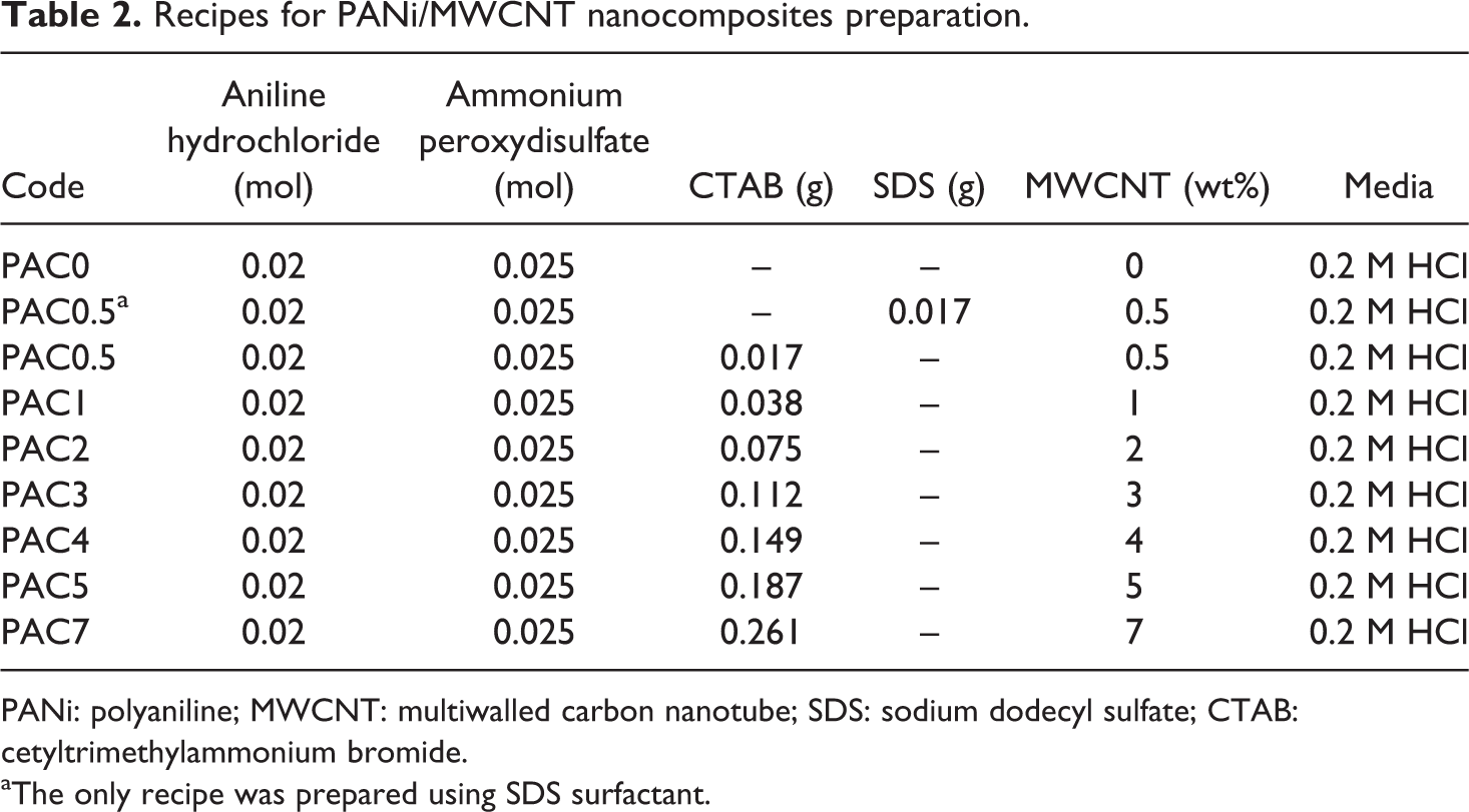
PANi: polyaniline; MWCNT: multiwalled carbon nanotube; SDS: sodium dodecyl sulfate; CTAB: cetyltrimethylammonium bromide.
aThe only recipe was prepared using SDS surfactant.
Characterization
Electrical conductivity measurement
The conductivity measurements were performed using both two- and four-point methods at room temperature. The schematic setups for both the measurement methods are shown in Figure 1. The dried powders of PANi and its composites containing various MWCNT levels were compression molded in a stainless steel mold as thin slabs (1 × 1 × 0.4 cm3) and disks with 15 mm in diameter and 1 mm thickness (Figure 2(a)). The four-probe resistivity of the disk specimens was measured according to the procedure provided by Blythe. 53 For two-point measurements, two flat edges of the prepared thin slabs were painted with silver paste to adhere thin copper sheets to the edges. The copper sheets act as two electrodes for subsequent two-point direct current (DC) conductivity measurements. The average electrical conductivity on four test specimens was taken to obtain a reliable value.
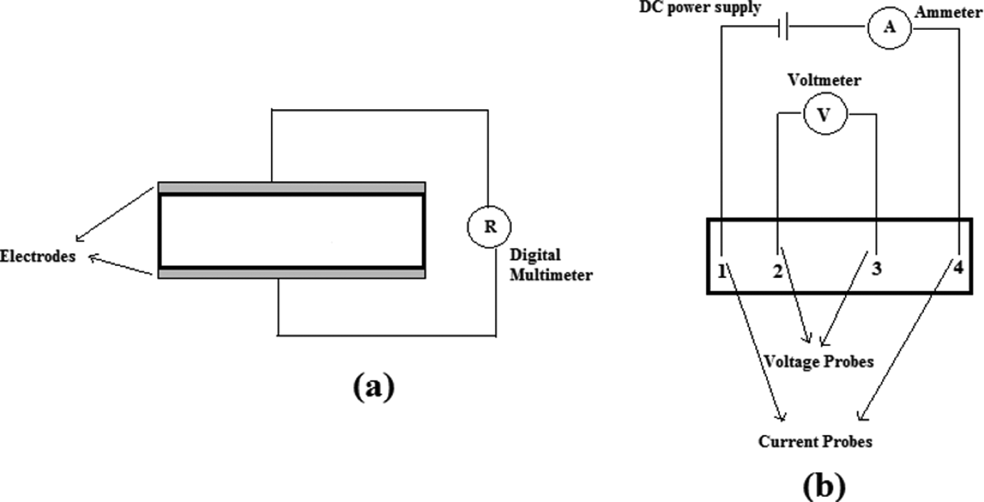
Schematic representation of (a) two-point and (b) four-probe methods.
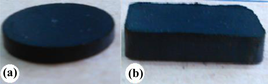
PAC0 specimen with (a) disk and (b) thin-slab geometries prepared for conductivity and microwave absorption measurements, respectively.
Chemical structure and morphology
The chemical structure of the neat PANi and PANi/MWCNTs samples was studied using a Fourier transform infrared spectrophotometer (FT-IR, Shimadzu, Japan). All spectra in the range of 400–4000 cm−1 with a 2-cm−1 spectral resolution were obtained from compressed KBr pellets in which the powder samples were dispersed. The nature of interactions between the MWCNTs and PANi was investigated using Raman spectroscopy (SENTERRA, German, Spectral Resolution: <3 cm− 1, Spectral Range: 200–3500 cm− 1, Laser wavenumber: 785 nm), a spectroscopic technique based on inelastic scattering of monochromatic light. The microstructure of the neat PANi and PANi/MWCNT nanocomposites was studied by means of field emission scanning electron microscopy (FESEM, Hitachi S-4160, Japan). The samples were first fractured in liquid nitrogen and then gold sputtered to coat a very thin layer of gold on the fractured surfaces before microscopy observation.
The EMI shielding measurement
The EMI shielding properties of the conducting specimens were measured in the X-band range of 8.2–12.4 GHz utilizing a vector analyzer (PNA E8362B, Agilent, USA). For this purpose, the rectangular cubic samples (23 × 11 × 4 mm3) prepared with compression molding were placed in the waveguide flanges of network analyzer (Figure 2(b)). The electromagnetic waves were glinted to the samples, and the relative permittivity (ε r) and permeability (μ r) were measured.
Results and discussion
The ANi oxidative polymerization
Chemical oxidative polymerization of ANi in the presence or absence of MWCNTs was carried out in an aqueous solution containing a surfactant and dopant. In the primary step of the polymerization, the ANi cationic radicals were formed and then N- and para-radical cations were coupled head-to-tail to produce dicationic dimer species. Re-aromatization of dimers reverted them to their neutral state and produced an intermediate so-called p-aminodiphenylamine (PADPA). 54 In this state, the color of the solution changed to pink. The PADPA was oxidized to two diradical cations during the third step of polymerization. Progressing oxidization changed the solution color to dark blue because of formation of protonated pernigraniline. Thereafter, the pernigraniline was reduced to the green emeraldine salt by the residual ANi in the solution. The color change continued until the blue pernigraniline completely converted to the green emeraldine. 55 The schematic representation of the oxidation of ANi hydrochloride with APS is shown in Figure 3.
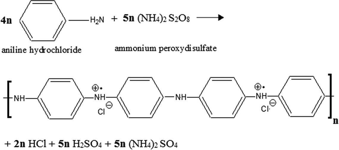
Schematic representation of the ANi hydrochloride oxidation with ammonium peroxydisulfate.
Electrical conductivity
Effect of temperature and dopant type
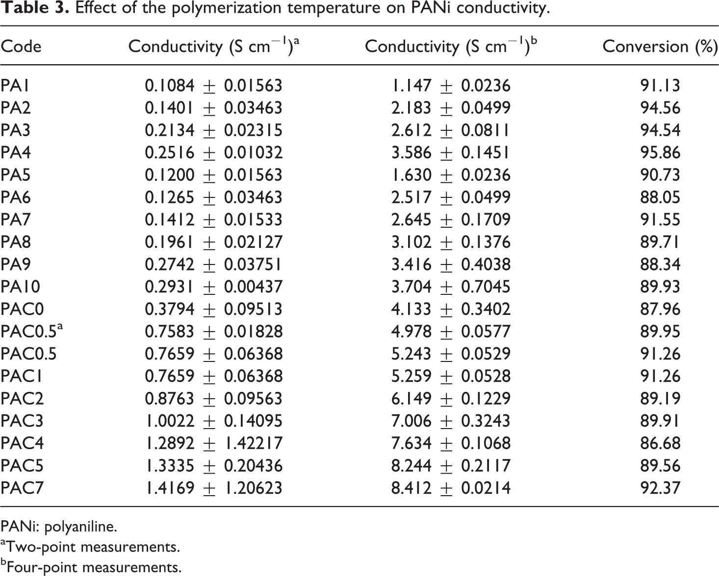
The effect of reaction temperature on the electrical conductivity of PANi is shown in Table 3. The polymerization was carried out in DDI media and prescribed temperatures (0, 3, 9, and 25°C) for compression purposes. As shown, the measurements based on four-probe method resulted in higher conductivities when compared with the two-probe method. In the former method, the conductivity was increased from 1.1472 S cm−1 to 3.5867 S cm−1 as the temperature decreased from 25°C to 0°C. The reason to use both the methods was to compare the results of two- and four-probe procedure and to show the high accuracy of the latter method in comparison with the former method in practice. In addition, lowering the temperature enhanced the conversion of oxidative polymerization to some extent (Table 3). The conductivity of PANi with a conjugated π-electron system depends on high mobility of charge carriers. Therefore, decreasing the temperature may result in polymer chains with high molecular weight and low structural defects, both of which increase the electrical conductivity.
Effect of the polymerization temperature on PANi conductivity.
PANi: polyaniline.
aTwo-point measurements.
bFour-point measurements.
The ANi and its polymerization products contain nitrogen-bearing groups with different basic activity. Therefore, the acidity (pH) of the reaction media plays a crucial role in oxidative polymerization of ANi. The ANi reacts in an acidic medium with different pH to produce ANi salt, while it exhibits a neutral structure in a weak acidic or basic media. Although the effect of polymerization temperature and dopant type on the electrical conductivity of PANi was studied by some researchers, the determination of proper polymerization conditions, for example, temperature and dopant type, for synthesis of subsequent PANi/MWCNT nanocomposite was the initial goal of this research work. For this purpose, the effect of HCl and H2SO4 and their mixtures as dopants was examined at different polymerization temperatures. Figure 4 shows the effect of HCl/H2SO4 weight ratio on the electrical conductivity of PANi. The electrical conductivity was increased with increasing HCl/H2SO4 ratio. Charge carrier mobility between the PANi chains and proton (H+) affects the electrical conductivity. Reduction in the electrical conductivity with increasing H2SO4 level can be attributed to the lower carrier mobility of the voluminous sulfate anion (
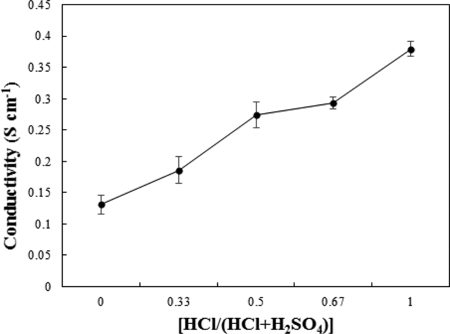
Effect of acidic media on the electrical conductivity of PANi measured by two-point method.
For nanocomposite preparation, the use of a suitable surfactant was necessary to disperse the MWCNTs in the reaction media appropriately. First, ANi was polymerized in the presence of 0.5 wt% MWCNTs, which were stabilized using SDS or CTAB as dispersing agents. The reinforced PANi using the cationic surfactant, that is, CTAB, exhibited a higher electrical conductivity, 5.20 ± 0.0529 S cm−1, when compared to the SDS synthesized nanocomposite with a lower electrical conductivity, 4.978 ± 0.0577 S cm−1. In the nanocomposite prepared using SDS, more granular structures were observed showing a small amount of polymer growth on the nanotubes (Figure 5(a) and (b)). On the contrary, in the CTAB-prepared nanocomposites (Figure 5(c) and (d)), the tubular morphology was more obvious than the granular one. As a result, CTAB as a surface active agent outperformed SDS. Accordingly, CTAB was selected as the suitable surfactant for preparing the PANi nanocomposites with various MWCNT levels.
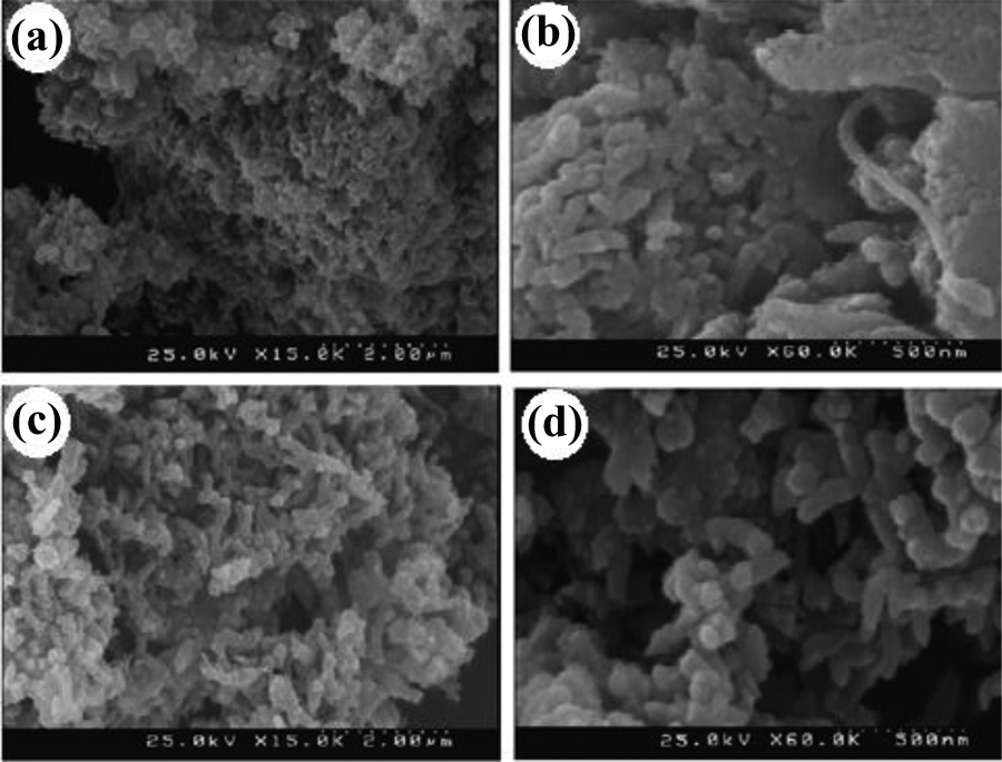
FESEM micrographs of PANi/0.5 wt% MWCNT nanocomposites prepared using (a, b) SDS and (c, d) CTAB dispersing agent.
Figure 6 shows the electrical conductivity of the MWCNTs-reinforced PANi specimens containing 0–7 wt%. As shown, the four-point electrical conductivity of the PANi was increased from 5.93 S cm−1 to 9.08 S cm−1 with increasing 7 wt% MWCNTs. The highly ordered MWNTs, especially at higher nanotubes levels, enhanced the electrical conductivity of the polymeric matrix by increasing the conjugation length of the PANi chains. The nanotubes also facilitated the charge movement in the composites and, therefore, increased the mobility of charge carriers. The electrical conductivity values of the resultant PANi/MWCNT nanocomposites prepared using CTAB and dodecylbenzenesulfonic acid sodium salt as dispersing agents were higher than the conductivity values of other published works, which used the same agents. 56,57 Chakraborty et al. obtained a maximum electrical conductivity of 6 × 10⁻³ S/cm for PANi/ 4 wt% MWCNT nanocomposite prepared in the presence of CTAB. 56 The electrical conductivity of 10−2 S/cm was obtained for PANi/CNT hybrid materials, which were prepared using a high CNTs content of 9 wt% in the presence of dodecylbenzenesulfonic acid sodium salt. 57 Zhang et al. obtained an electrical conductivity of 1.35 S cm−1 for PANi synthesized in the presence of 25 wt% CNTs and CTAB as a dispersing agent. 58 In this research work, the approximately same above-mentioned conductivity corresponds with the PANi reinforced only with 2 wt% MWCNTs using CTAB.
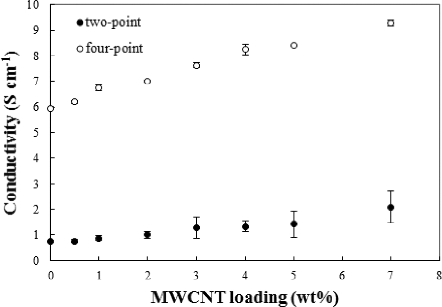
Electrical conductivity of PANi/MWCNT nanocomposites versus MWCNTs loading.
Aging of nanocomposites
In general, the environmental stability of conducting PANi is related to its physical/chemical aging and the extent of reaction of the polymer backbone with oxygen and moisture in the surrounding atmosphere.
59
Figure 7(a) indicates the electrical conductivity of PANi specimens versus aging time at 25°C. As expected, the undoped chains (PA1) exhibited the lowest electrical conductivity and the highest degradation rate in comparison with the doped specimens. A similar declining trend was found for the doped specimens prepared at the same temperature using different dopants (PA5 and PA6). The higher degradation was observed for the more conductive specimen doped Cl− with PA6 than the
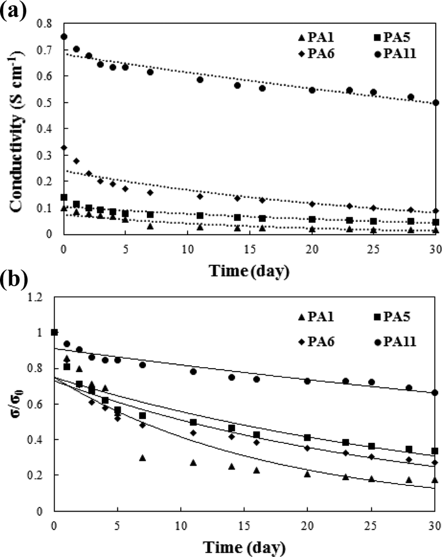
Electrical conductivity of the neat PANi versus aging time.
The electrical conductivity ratio (σ/σ 0) of the PANi specimens was plotted as a function of aging time (Figure 7(b)). The aging mechanism of all the composites follows a first-order kinetic model according to the following equation 61

where σ 0 is initial electrical conductivity and σ is conductivity at any time. This behavior suggests that the reaction of oxygen and air moisture with PANi backbone is the limiting step in electrical conductivity decay. Figure 8(a) indicates the aging of the conducting PANi/MWCNT nanocomposites. To reveal the effect of MWCNTs on the aging behavior, the conductivity variation is shown for the neat PANi and its nanocomposites containing various MWCNT levels. The electrical conductivity of the PANi and its composites was decreased with aging time. In fact, the reaction of PANi’s active sites with oxygen and water vapor resulted in conductivity decay. However, the incorporation of MWCNTs in the polymeric matrix may improve the structural regularity and, subsequently, the compact arrangement of the PANi chains which reduces the reaction of the polymeric backbone with impurities such as oxygen and moisture.
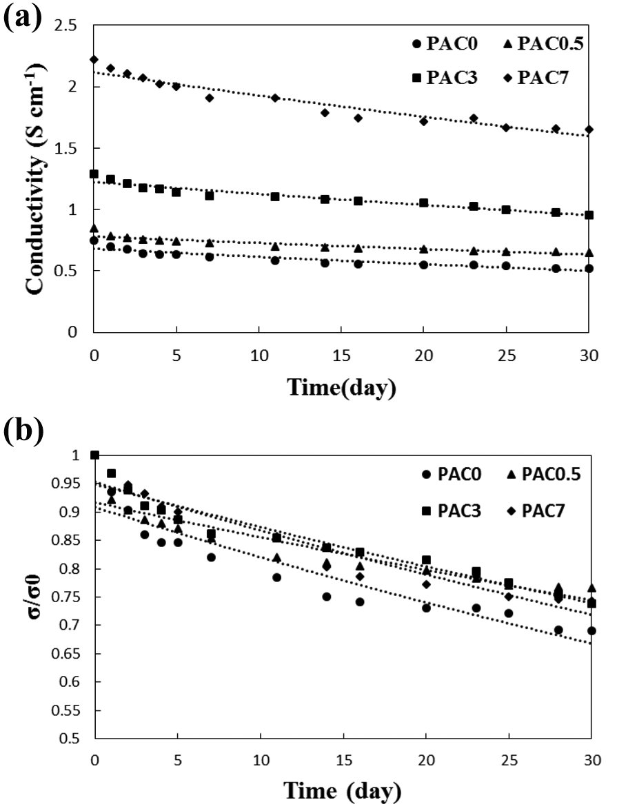
Electrical conductivity of PANi/MWCNT nanocomposites versus aging time.
The electrical conductivity ratio of the nanocomposites was curve fitted by the first-order kinetic model (Figure 8(b)). The results reveal a similar mechanism for the reduction of electrical conductivity. However, the electrical conductivity of the nanocomposites decayed more slowly presumably due to the more compact arrangement of the PANi layers formed on the nanotube surface. This compact structure may retard the anion escape and decrease the diffusion rate of the oxygen and moisture which leads to slower conductivity decay.
Morphology of nanocomposites
Figure 9 indicates FESEM micrographs of the CTAB-synthesized PANi/MWCNT nanocomposites containing various MWCNT contents, 0, 0.5, 3, and 7 wt%. The micrograph of the neat PANi is also shown for comparison purposes. As seen, the morphology of the synthesized PANi was changed by the addition of MWCNTs. Granular PANi particles formed agglomerates while the addition of MWCNTs changed the particle morphology to tubular shape (Figure 9(a) and (b)). The length and diameter of the tubular coated particles increased with further addition of MWCNTs (Figure 9(c)).
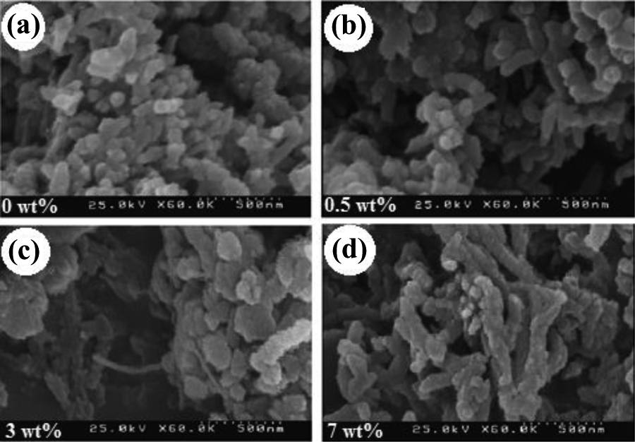
FESEM micrographs of the nanocomposites with various MWCNT contents: (a) 0, (b) 0.5, (c) 3 and (d) 7 wt% (CTAB was used as dispersing agent in all the nanocomposite specimens).
The MWCNTs with a high specific surface area (200 m2 g−1) provide many adsorption sites for PANi segments. The ANi hydrochloride could be polymerized on the surface of MWCNTs. At low MWCNT levels, the nanotubes are covered by PANi forming very low agglomerated structures. This behavior can be attributed to high ratio of the free PANi formed in the reaction media to PANi formed on the surface of MWCNTs. As shown in the micrographs, less agglomerates were observed with increasing the MWCNTs level.
Chemical structure
Figure 10 shows FT-IR spectra of the MWCNTs, PANi, and PANi/MWCNT nanocomposites. For the neat PANi (PAC0) and its composites with 0.5 (PAC0.5), 3 (PAC3), and 7 wt% MWCNTs (PAC7), the peak observed at 3424 cm−1 corresponds to N–H symmetric stretching, and absorption bands at 2922 and 2850 cm−1 are attributed to the asymmetric and symmetric stretching vibrations of C–H, respectively. The intensity of these bands is similar to each other. In addition, the peaks at 1564 and 1472 cm−1 are related to the stretching vibrations of C=C in the aromatic nucleus, and the band at 1134 cm−1 is relevant to the stretching model of C=N in the aromatic ring of PANi chain backbone. The intensity of these bands in the nanocomposite samples is less than the pure PANi.
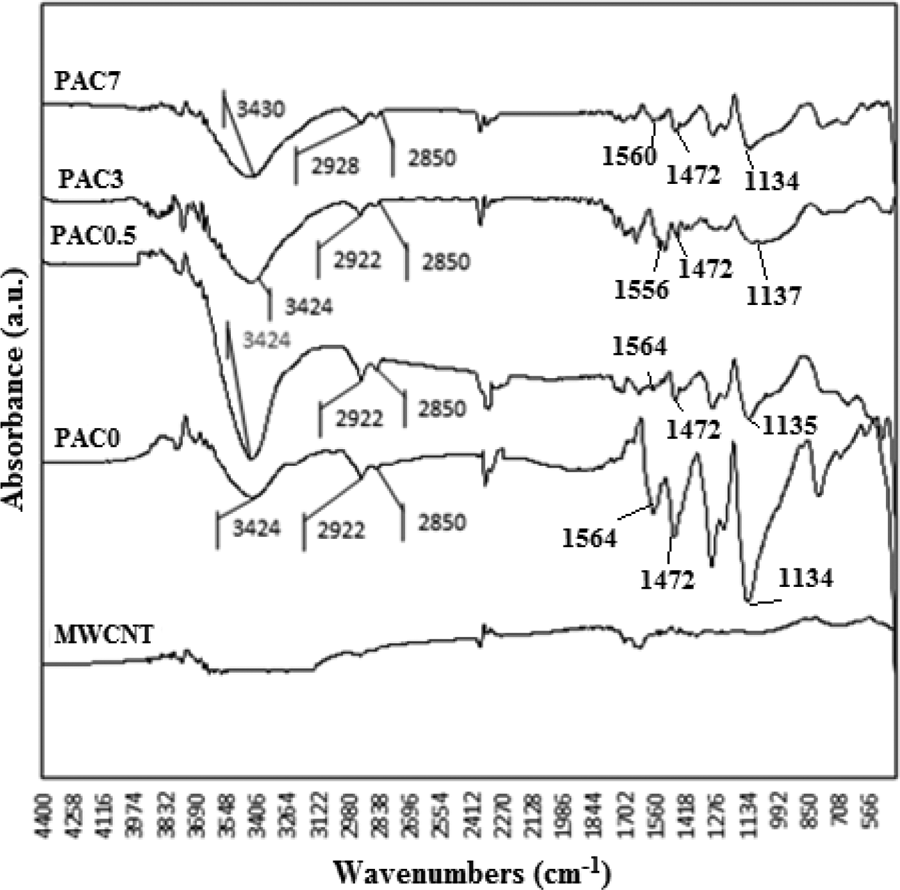
FT-IR spectra of the PANi and PANi/MWCNT nanocomposites.
Raman spectra (Figure 11) can show the nature of probable interactions between the MWCNTs and PANi in the nanocomposites. The peak appeared at 1309 cm−1 in the neat MWCNT spectrum is assigned to the G band and tangent vibrations of carbon atoms. This peak is a good criterion for determining graphite content of MWCNTs. 62 The peak observed at 2624 cm−1 is the second harmonic of D band known as G′ band. This band indicates the ordered structure of the material due to the second-order biphonon transmittal leading to an elastic phonon. The weak peaks observed at 1580 and 1607 cm−1 are due to a biphonon process. In addition, the peak appeared at 1597 cm−1 corresponds to the disordered G′ line. The peak at 1311 cm−1 in the Raman spectrum of PANi is related to the stretching vibration of C=C bond of ANi quinoid ring. The characteristic peaks of MWCNTs and PANi are observed in the spectrum of PANi/MWCNT nanocomposite (Figure 11). The peak appeared at 2612 cm−1 is assigned to the D band of MWCNTs. The intensity of D band for PANi in the nanocomposite is higher than that observed for the MWCNTs. No new peak was observed in the spectrum of the nanocomposite specimen indicating the lack of formation of new chemical bond between MWCNTs and PANi. However, the shift in the characteristic peaks of MWCNTs in the spectrum of the nanocomposite can be attributed to π–π interactions between the MWCNTs and PANi chains. The quinoid and benzoid vibrations at 1564 and 1472 cm−1 show the emeraldine salt form of PANi and PANi/MWCNT nanocomposites. The positions of quinoid and benzoid vibrations are independent of MWCNTs at the lower loadings. However, the quinoid deformation is slightly shifted to lower wavenumbers at the higher MWCNT contents. This change can be related to polymerization of PANi chains on the MWCNTs and more planar conformation of PANi along MWCNTs. Comparing the pure PAN0 and PANi-MWCNT composites showed a lowering in the ratio of benzoid to quinoid intensity peaks, which indicates the stabilized form of the nanocomposites. These changes interpret the charge transfer between the PANi and MWCNTs and, thus, improving the electrical conductivity of PANi.
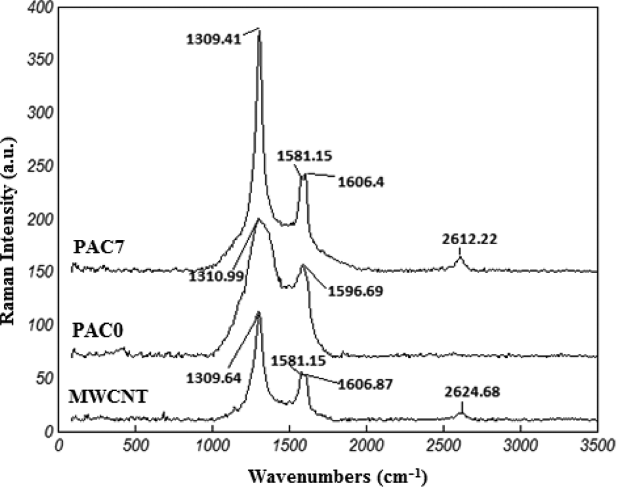
Raman spectra of the MWNTs, PANi and PANi reinforced with 7 wt% MWCNTs.
The EMI shielding properties
Microwave absorption of the PANi/MWCNT nanocomposites was measured in the frequency range of 8.2–12.4 GHz (X-band). Figure 12(a) and (b) shows the dielectric constant and dielectric loss of the neat MWCNTs, PANi, and PANi/MWCNT nanocomposites. As shown, increasing MWCNTs level enhanced the dielectric constant of the PANi. Although PANi/MWCNT nanocomposites show a complex behavior due to their heterogeneous structure and phases having different electrical conductivities, the EMI shielding properties are dependent on filler conductivity and content, applied frequency range, and shield thickness. 63,64
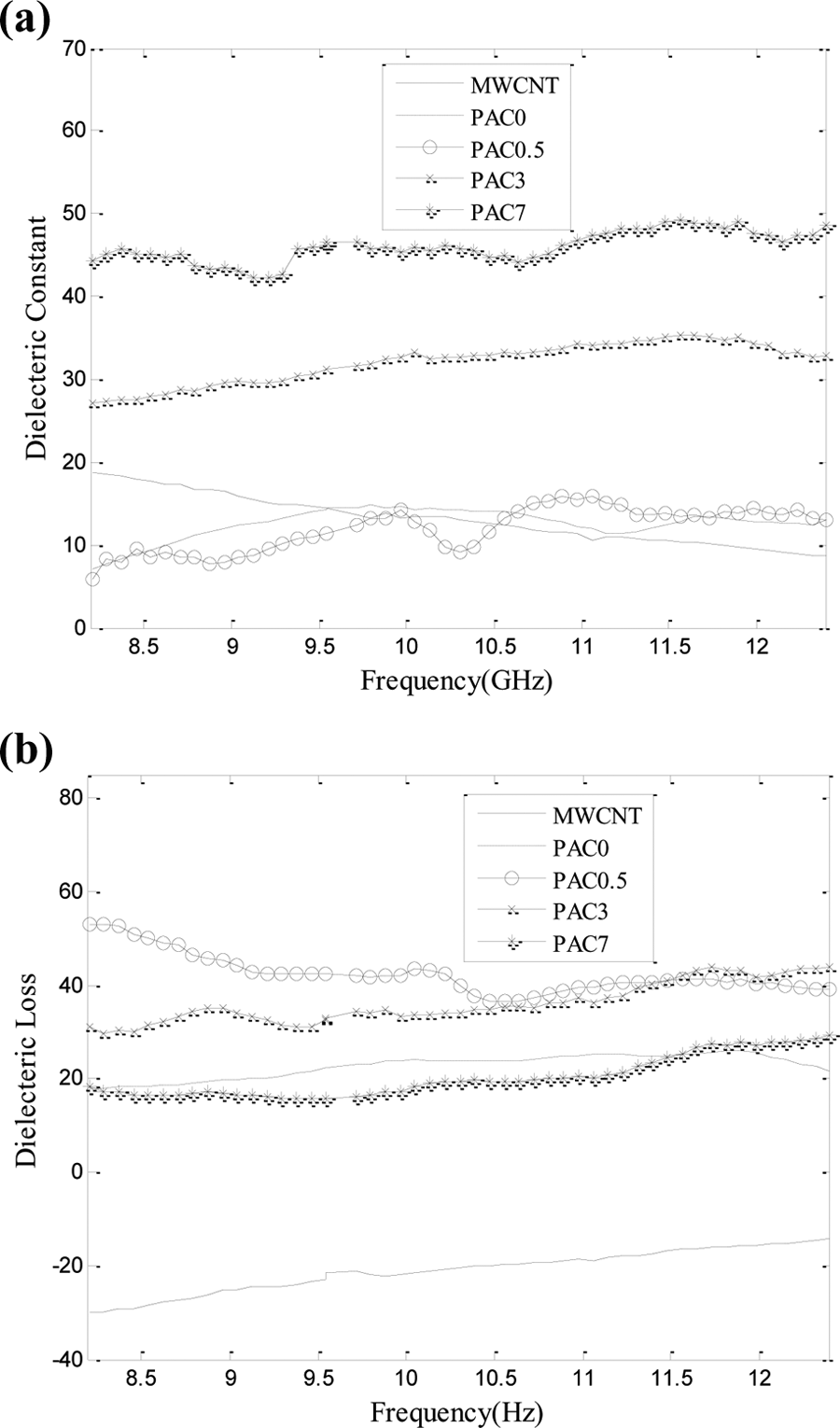
(a) Dielectric constant and (b) dielectric loss of MWCNTs, PANi, and its nanocomposites with 0.5, 3 and 7 wt% MWCNTs.
In fact, the MWCNTs can be considered as electrical resistors containing free charges. Two CNTs and the polymeric matrix in between could be imagined as a nanocapacitor in the nanocomposites. Accordingly, the PANi/MWCNT nanocomposites are assumed to be consisted of a large number of nanosized resistors and capacitors. Dielectric constant is a criterion of nanometric capacitors and polarization centers. However, structural defects in MWCNTs may create semiconducting zones and, consequently, causes two zones with different electrical conductivities in the molecular structure of MWCNTs which result in polarization of electrical charges. Increasing the MWCNTs level enhanced the polarization loss and dielectric constant due to increasing the number of resistors and nanocapacitors in the resultant nanocomposites. In addition, conducting networks created by MWCNTs act as charge careers. As shown in Figure 12(b), the incorporation of MWCNTs up to 3 wt% in the PANi increased the dielectric loss to some extent, while further increase lowered the dielectric loss to the amount of PANi.
Figure 12 shows the absorption and reflection losses of the neat PANi, MWCNTs, and PANi/MWCNT nanocomposites. Reflection loss is a result of interaction between the conducting nanoparticles dispersed in the polymeric matrix and electromagnetic field. This parameter is proportional to shield electrical conductivity to magnetic permeability ratio (σ r/μ r). Increasing MWCNTs level enhanced the magnetic permeability more than the electrical conductivity; hence, the σ r/μ r value and reflection loss were decreased. Absorption loss is due to heat loss under action between the electrical and magnetic bipolars in the shield and, therefore, is a function of σ r μ r. By incorporating MWCNTs in the polymeric matrix, the gap between nanotubes decreases, and thus, the polarization and the absorption loss of the nanocomposites increase. Figure 13 indicates the SE of the PANi and its nanocomposites containing various MWCNT levels. As shown, the SE is almost independent of frequency.
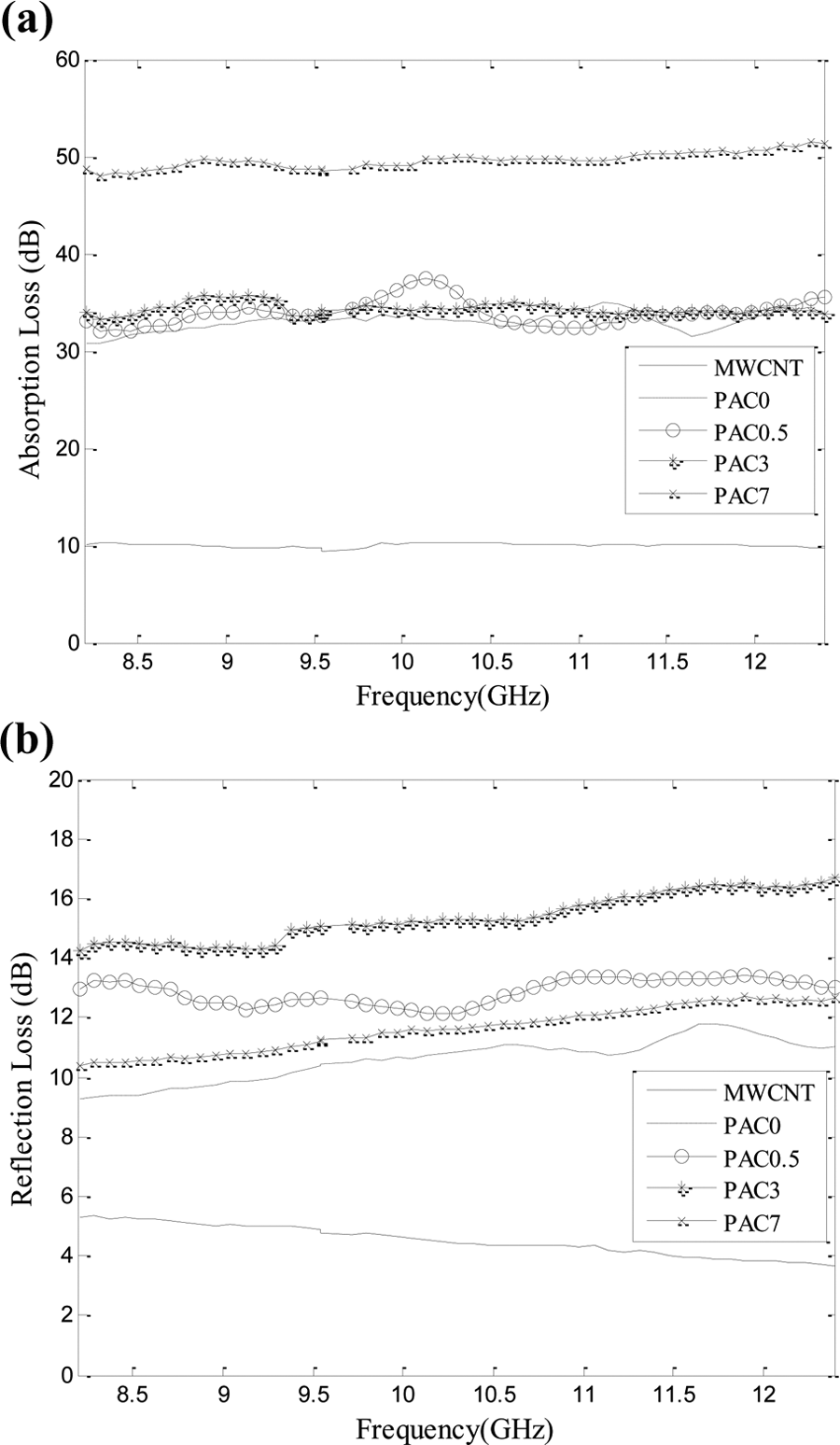
(a) Absorption loss and (b) reflection loss of: MWCNTs, PANi, and its nanocomposites with 0.5, 3, and 7 wt% MWCNTs.
Increasing the MWCNTs level and, thereby, the number of free electrical charges and electrical/magnetic bipolars decreased the electromagnetic wave and enhanced the SE value. Moreover, an increase in the MWCNTs level is associated with more interactions between the polymeric matrix and the nanotubes which resulted in a stronger electrical field and electronic polarization of the polymeric layer. As expected, by increasing the MWCNTs content and, consequently, the electrical conductivity of the resulting PANi/MWCNT composites (Table 3), the SE of the conducting composites enhanced. This behavior may be connected to increasing the number of nanocapacitors and reducing the thickness of the PANi layer between the CNTs. Therefore, the number of free electrical charges and the polarization of electrical charges in the dielectric layer of the nanocapacitors increased.
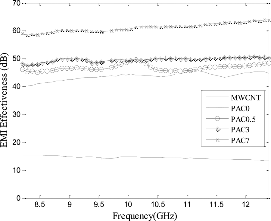
Shielding effectiveness (SE) of: MWCNTs, PANi, and its nanocomposites with 0.5, 3, and 7 wt% MWCNTs.
Conclusion
The neat PANi and PANi/MWCNT nanocomposites were successfully synthesized via chemical oxidative polymerization. The results showed that the electrical conductivity of the neat PANi was dependent on the dopant type and polymerization temperature. The differences in conductivities were due to different structural orders of the resultant PANi. The highest electrical conductivity corresponds with a proper polymerization condition, using HCl as dopant at polymerization temperature of 0°C. The electrical conductivities measured by four-point method were higher than those obtained from the two-point method. The aging of the PANi specimens was studied using a simple kinetic model, which indicated that the oxygen and air moisture would react with polymeric backbone. The electrical conductivity of the PANi/MWCNT nanocomposites increased with increasing the MWCNTs level. The highest conductivity, 9.294 S cm− 1, was observed for the nanocomposite containing 7 wt% MWCNTs. FESEM images showed a uniform and thick coverage of the PANi layer on the nanotubes surface. At the lowest MWCNTs level (0.5 wt%), the nanotubes were covered with a thinner layer of PANi granular agglomerates. The absorption and reflection losses and SE of the neat PANi and its nanocomposites were studied. The PANi/MWCNT nanocomposite containing 7 wt% MWCNTs showed a maximum SE value close to 60 dB in the frequency range of 8.2–12.4 GHz. The absorption loss was increased from 30 dB for the neat PANi to 50 dB for the nanocomposite containing 5 wt% MWCNTs. Since the absorption was dominant in total SE, the nanocomposites can be used for shielding applications in the X-band range.
Footnotes
Acknowledgements
The authors gratefully appreciate the Iranian Nanotechnology Initiative Council and the vice-president for research and technology of Iran University of Science and Technology (IUST) for their partial financial supports.
Declaration of Conflicting Interests
The author(s) declared no potential conflict of interest with respect to the research, authorship, and/or publication of this article.
Funding
The author(s) received no financial support for the research, authorship, and/or publication of this article.