
Abstract
This study investigates the influence of macroscale skin-core residual stress and cooling rate on the impact response of aerospace grade carbon fibre/polyphenylenesulphide (CF/PPS). Numerical simulations are developed which analyse the thermal shrinkage and residual stress development of unidirectional (UD) lay-up configurations. Macroscale skin-core residual stresses are then incorporated into low-velocity impact simulations based on an orthotropic elastic material model. Interlaminar delamination is modelled using a bilinear cohesive traction–separation law, and intralaminar failure is modelled using the Chang–Chang strength-based failure criterion. The simulation results are compared with the results of drop tower impact tests showing qualitative agreement in terms of maximum impact force and delamination. The results of this work highlight the importance of cooling rate on the interlaminar delamination and intralaminar failure of CF/PPS.
Introduction
Thermoplastic composite (TPC) materials including TPCs reinforced with carbon fibre (CF) have been successfully applied in a number of primary and secondary aircraft structures. Thermoplastic matrix materials have a number of advantages compared to thermosets including low relative cost and processing time, high toughness and recyclability. 1 However, similar to carbon fibre-reinforced plastic (CFRP), TPCs including those reinforced with CF are susceptible to impact damage sustained during manufacture and/or in-service. 2 Low-energy and low-velocity impact damage can result in significant damage leading to subsurface matrix cracking, fibre fracture and delamination. An additional factor limiting TPCs use in high-performance applications is associated with the presence of thermal residual stresses. Thermal stresses are introduced into thermoplastic materials during processing primarily due to variations in coefficients of thermal expansion (CTE) between reinforcement fibres and matrix. In addition to CTEs, the magnitude of the residual stresses depends on the elastic coefficients of the plies, fibre volume fraction, morphology/crystallinity of the matrix and the processing conditions.
Parlevliet et al. describe three discrete scales of residual stress formation on the level of the fibre, individual laminae and laminate. 3 The cooling rate in relatively thick high-performance laminates tends to be slow in the centre (core) of the laminate than at the surface (skin). This results in a parabolic stress distribution with compressive residual stress in the surface plies and tensile stresses in the centre. Thermal stresses developed in this manner are referred to as skin-core stresses and are often highest in thicker laminates with faster cooling rates. TPC materials such as carbon fibre/polyetheretherketone (CF/PEEK) which are fast cooled also exhibit a parabolic stress distribution, and the gradient of the residual stress has been shown to be higher in cross-ply laminates than in unidirectional (UD) laminates. 4–5 The crystallinity of semicrystalline thermoplastic matrices has also been shown to influence the development of skin-core residual stress when a nonuniform cooling rate through the thickness of the laminate exists. 3 Nielsen and Pyrz have suggested that fast cooling to the crystallization temperature then slow cooling to room temperature would lower residual stresses. 6 Skin-core residual stresses can also be reduced through a process of annealing which is typically applied to thick laminates. Annealing is the process through which a composite laminates temperature is raised above the glass transition temperature of the matrix allowing the residual stresses to relax in semicrystalline composites. A number of models have been developed to predict the influence of residual stress on mode I and mode II fracture toughness properties including an exact solution for mode I strain energy release rate. 7 Previous studies highlighted by Parlevliet et al. suggest the thermal residual stresses must be considered when predicting fracture toughness of composite laminates, since the stresses decrease the fracture toughness properties. 8 While many studies have investigated the influence of residual stress on fracture toughness, tensile and flexural properties, Parlevliet et al. note there is a gap in knowledge concerning the influence of residual stress on impact damage. 8
The most important mechanical properties that influence the performance of composite laminates during impact are the matrix ductility or failure strain and the mode II strain energy release rate. 9 Matrix ductility affects the critical transverse strain at which transverse matrix cracks initiate during shear. The mode II strain energy release rate also has a direct influence on a laminates ability to resist the initiation and propagation of delamination during drop weight impact. Gao et al. have noted that the mechanical properties and fracture resistance of CF/PEEK may be optimized by controlling the processing conditions in particular the cooling rate. 9 The cooling rate can be used to change the degree and morphology of crystallinity in the matrix and interphase material surrounding the fibres. In the case of CF/PEEK, slow cooling was shown to improve the fibre–matrix interface bond strength and strength/stiffness. Fast cooling increases the ductility of the PEEK matrix by increasing the strain energy release rate and impact resistance. In their studies, Gao et al. investigated the influence of cooling rate on the impact response of different matrix materials including CF/epoxy, slow-cooled CF/PEEK and fast-cooled CF/PEEK. 9 The authors found that CF/PEEK specimens cooled at a fast rate 70°C min−1 resulted in a lower degree of crystallinity (DOC) 30% and a smaller size of spherulite crystals with a corresponding higher matrix ductility. Spherulite crystals are spherical semicrystalline regions formed inside a polymer during crystallization and are composed of ordered lamellae which result in higher density, hardness and also brittleness of the spherulites. CF/PEEK specimens cooled at a fast rate were shown to resist the onset of delamination more than CF/epoxy and slow-cooled CF/PEEK. Slower cooling at 1°C min−1 resulted in a higher DOC, 38%, and a larger size of spherulite, as large as a few hundred micrometers in diameter, causing embrittlement in the PEEK matrix. The spherulite size is strongly influenced by cooling rate with a lower cooling rate resulting in a larger spherulite size with a higher degree of molecular perfection and a lower melting temperature. 10 The delamination area was smaller in the order of fast-cooled CF/PEEK, slow-cooled CF/PEEK and CF/epoxy laminates for a given impact energy.
Understanding the influence of laminate (macroscale) skin-core residual stress and cooling rate on the impact tolerance of thermoplastic CFRP is important to improve the design of future components. The aim of the current study is to determine the influence of macroscale skin-core residual stress and cooling rate on the impact response of aerospace grade CF/polyphenylenesulphide (PPS) by experiment and numerical simulation. In the first section of this article, the thermal–mechanical material properties for CF/PPS in a UD ply configuration are presented followed by a description of impact and non-destructive testing. Numerical simulations designed to estimate the influence of macroscale skin-core residual stress and cooling rate on the impact response of CF/PPS are then presented. The simulation results are then compared with the results of drop tower impact tests.
Materials
Thermal–mechanical properties
TenCate Cetex® TC1100 PPS resin system was used in conjunction with AS4A UD CF tape at a fibre volume fraction V f = 0.5911. Laminates were prepared with a lay-up sequence [0°]48 measuring 100 × 100 × 7 mm3 in dimension. The relevant thermal–mechanical property data for slow (8°C min−1) and fast cooling rates (150°C min−1 inside laminate and 230°C min−1 at surface of laminate) are shown in Table 1, where subscript 1 denotes the material longitudinal (fibre) direction and subscripts 2 and 3 denote the transverse (matrix) directions. 11,12
Thermal–mechanical property data for TenCate Cetex® TC1100 AS4A UD tape.
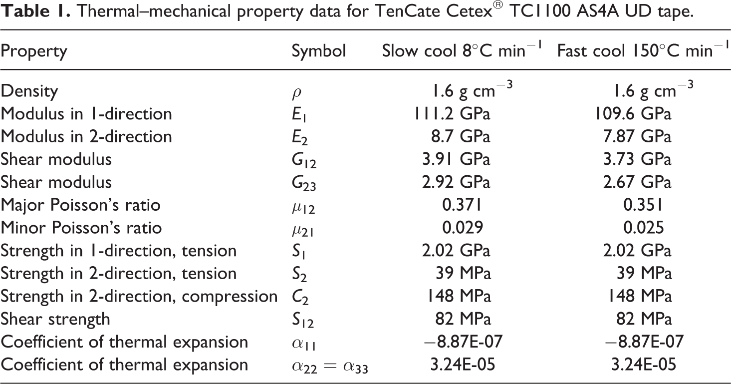
All of the material property data were measured at an ambient room temperature of 25°C. The mechanical properties for fast-cooled laminates were shown to have lower values of Young’s modulus E, shear modulus G and Poisson’s ratio μ when compared to the slow-cooled condition consistent with literature. 3 The CTE values were assumed to be the same in slow- and fast-cooled laminates. Critical strain energy release rate values GIC and GIIC presented in Figure 1 were measured from end notched flexure (ENF) and double cantilever beam (DCB) tests, respectively. 11 In the case of slow-cooled laminates, the GIC and GIIC values were 202 J m−2 and 1014 J m−2, respectively. Fast-cooled laminates showed an increase in GIC and GIIC of 282 J m−2 and 1705 J m−2, respectively. This increase in critical strain energy release rate is attributed to the reduction in crystallinity and change in morphology of the laminate during fast cooling.
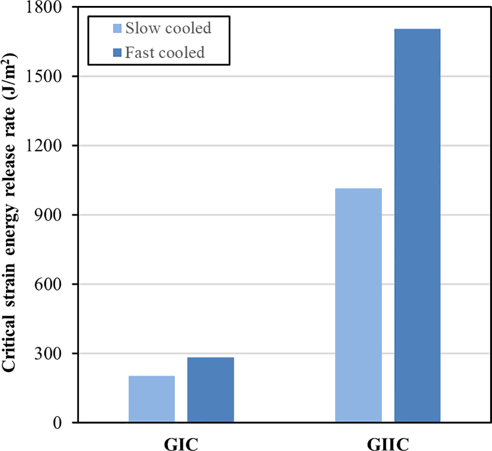
Comparison of mode I and mode II critical strain energy release rate values for slow- and fast-cooled specimens.
Characterization of crystallinity
The crystallinity of CF/PPS was measured using a differential scanning calorimeter (DSC) DSC8500, PerkinElmer Co., Ltd. (Waltham, MA, U.S.) Specimens of approximately 5.5 mg were prepared from prepreg sheet. The DSC procedure consisted of three thermal cycles: preheat, cool and heat. Specimens were heated in a preheat cycle from −50°C to 350°C at 100°C min−1 and then cooled at two different rates −10°C min−1 and −100°C min−1 to determine the dependence of crystallization temperate T c on cooling rate. Upon cooling, each specimen was reheated according to the preheat process. The DOC was calculated from the following equation:
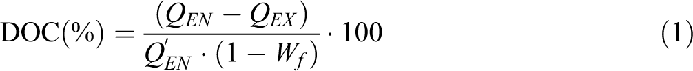
where QEN is the reaction heat per unit mass at the melting point and is measured from the area under the endothermic peak. QEX is the reaction heat per unit mass at crystallization and is measured from the area under the exothermic crystallization peak.
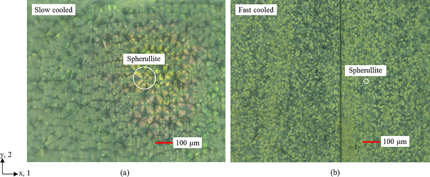
Photomicrographs obtained with a polarization microscope at 300× magnification showing the presence of spherulites in (a) slow- and (b) fast-cooled specimens for an equivalent CF/PPS material.
Experiments
Impact testing
Impact testing was performed at an ambient room temperature of 25°C using an IITM-18S-KW (Yonekura Mfg Co., Ltd., Osaka, Japan) test device with a hemispherical impactor measuring 5/8″ (15.875 mm) in diameter (Figure 3). The CF/PPS specimens were clamped from the impact side using a steel tool with a circular cut-out of 75 mm in diameter based on the JIS K7089 reference method. 14 Specimens were impacted with a drop weight of 5.6 kg at four impact energy values: 1 J, 3 J, 5 J and 7 J.
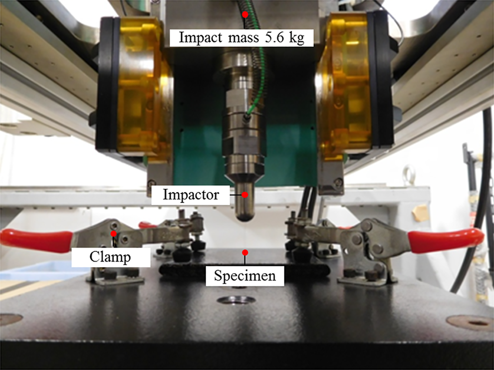
Drop tower impact test set-up.
Non-destructive inspection
The extent of external damage to the post-impacted specimens was characterized by visual inspection. Internal damage including the extent of delamination was characterized using a Toshiba Matrixeye™ NX 3D Toshiba Power Systems Inspection Services Co., Ltd. (Yokohama, Japan) ultrasonic test (UT) device with a 64-channel array probe.
Simulation set-up
Software
The finite element simulations were created using the preprocessing software LS-PrePost 4.2 and solved using LS-DYNA 971 R8.1.0 running on an HP Z840 workstation. 15 The thermal–mechanical simulations were solved using the implicit solver, and the impact simulations were solved using the explicit solver within LS-DYNA 971.
Material models
The influence of skin-core residual stress on interlaminar failure was assessed in simulations based on the material model *MAT_ORTHOTROPIC_THERMAL (MAT_21) which did not include intralaminar failure. Intralaminar failure was included in separate simulations without skin-core residual stress using the composite material model *MAT_COMPOSITE_DAMAGE (MAT_22). 15 This material model is based on the composite material model *MAT_ENHANCED_COMPOSITE_DAMAGE (MAT_54-55) and was developed to simulate orthotropic materials such as UD composite laminates. In the current work, the Chang–Chang strength-based failure criterion was used to simulate intralaminar failure. 15
The Chang–Chang failure criterion includes the following five material parameters: longitudinal tensile strength (S 1), transverse tensile strength (S 2), shear strength (S 12), transverse compressive strength (C 2) and the nonlinear shear stress parameter (γ) as defined in and reproduced here. 15 S 1, S 2, S 12 and C 2 are determined from material strength measurements, while the nonlinear shear parameter γ is defined by shear stress–strain measurements with a recommended value between 0 and 0.5. 15 In the present work, a value of γ = 0 was used resulting in the standard linear-orthotropic Chang–Chang model consistent with previous work and the results of tensile tests which do not show significant nonlinearity. 16 In plane stress conditions, the strain is related to the stress by the following equations:
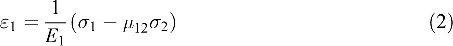
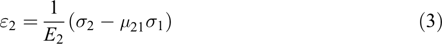
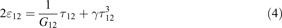
where ε is strain, E is Young’s modulus, σ is stress, μ is Poisson’s ratio, G is the shear modulus and τ is the shear stress. A fibre matrix shearing term is then used to supplement each damage mode:
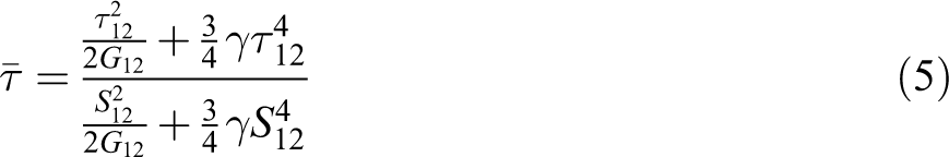
The failure of the matrix Fm is determined from:
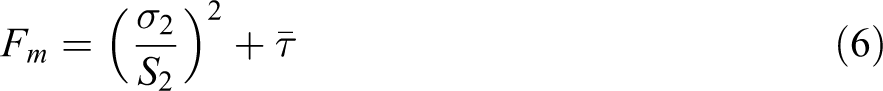
In equation (6) when failure occurs (Fm > 1), the material constants E 2, G 12, μ 12 and μ 21 are set to zero. In compression, the failure criterion is defined as follows:

In equation (7) when failure occurs (F comp > 1), the material constants E 2, μ 12 and μ 21 are set to zero. The final failure mode due to fibre breakage is defined as follows:
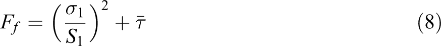
In this case when failure occurs (Ff > 1), the material constants E 1, E 2, G 12, μ 12 and μ 21 are set to zero. It should be noted that if the subscript 2 is replaced with 3 in the above criteria, then the above rules also apply to failures in the transverse 3-direction and the 1–3 plane.
Interlaminar failure was modelled using the bilinear cohesive material model *MAT_COHESIVE_MIXED_MODE (MAT_138) (Figure 4) which includes a bilinear traction–separation law with quadratic mixed-mode delamination criteria and damage formulation. 15,17 The mixed-mode failure displacement is calculated using the following power law failure criterion:

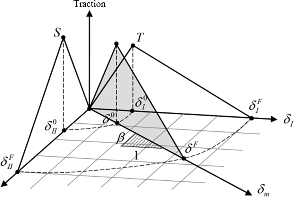
Schematic of mixed-mode cohesive element traction–separation law used in MAT_138. 15
where GI and GII are the mode I and mode II strain energy release rates, respectively. The critical strain energy release rates are defined as GIC and GIIC. The parameter ∝ in equation (9) is an empirical parameter derived from testing. In Figure 4, T and S are defined as the peak traction in the normal and tangential directions, respectively. The total mixed-mode relative displacement is defined as δm where δI and δII are the separation in the normal (mode I) and tangential directions (mode II), respectively. The onset of softening is denoted by δ0 with the ultimate mixed-mode displacement for total failure defined as δF. As indicated earlier, the critical strain energy release rate values GIC and GIIC for slow-cooled laminates were measured as 202 J m−2 and 1014 J m−2, respectively. 11 Fast-cooled laminates showed an increase in GIC and GIIC of 282 J m−2 and 1705 J m−2, respectively. 11 The stiffness normal to the cohesive element KI and in the plane of the cohesive element KII was 1.0E+14 N mm−3 with the peak traction in the normal σI, max and tangential σII, max direction given as 60 MPa. 18 A value of α = 1 was chosen based on its application in previous research where it has been shown to predict the delamination behaviour for a range of CFRP materials. 19 The accuracy of the bilinear cohesive material model MAT_138 was assessed by comparison to theory in earlier work through a series of validation studies involving quasi-static DCB, ENF and fixed ratio mixed-mode bending (FRMMB) simulations with UD [0°] specimens. 17
A rigid material model *MAT_RIGID (MAT_20) with the material properties of steel, ρ = 7850 kg m−3, E = 210 GPa, μ = 0.3, was used to simulate the impactor.
Thermal–mechanical impact model
In the fast-cooled simulations which included skin-core residual stress, the simulations were performed in two key steps involving a thermal–mechanical step followed by impact. During the thermal–mechanical step, the sublaminates were heated to produce a parabolic skin-core residual stress ±25 MPa compressive on the outside surface and tensile on the inside, as shown in Figure 5. This representative skin-core residual stress was based on the results of earlier ABAQUS simulations. 11 The skin-core residual stress was held initially constant during a second step involving impact. In the slow-cooled simulations without skin-core residual stress only, the impact step was performed.
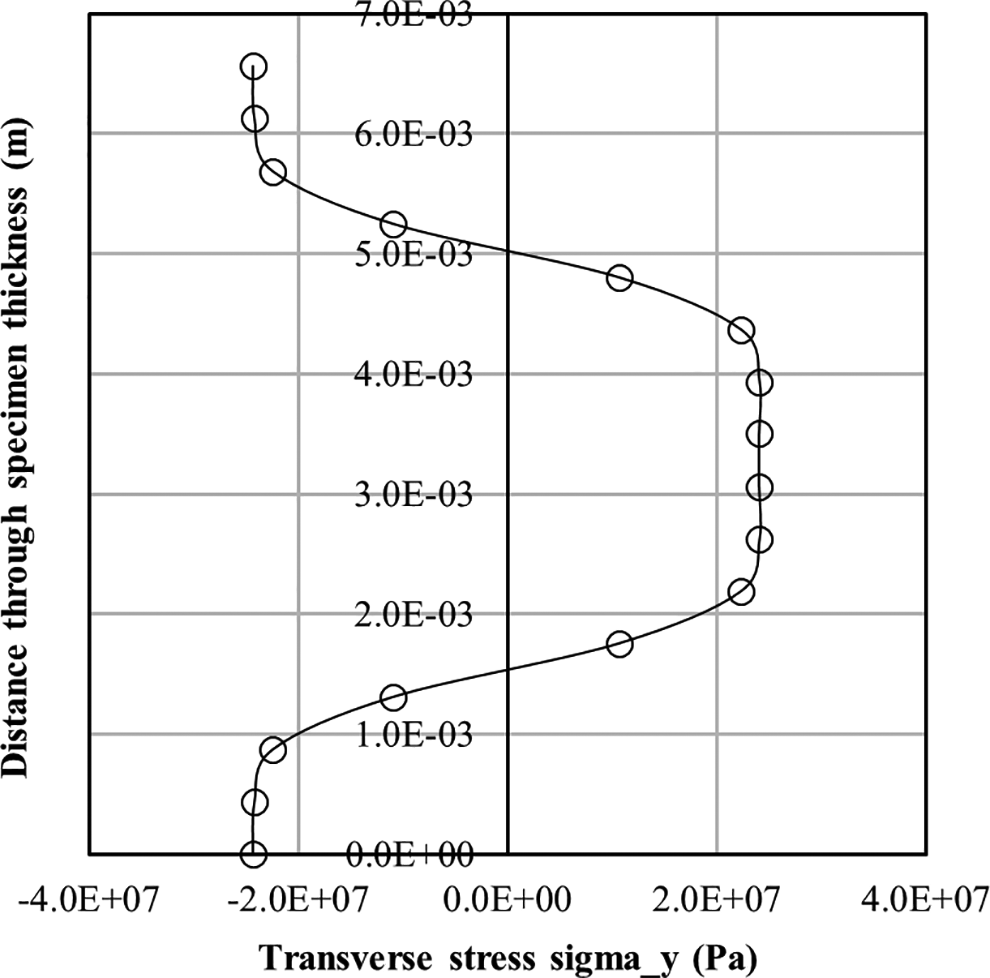
Representative skin-core residual stress profile obtained in fast-cooled simulations and used during impact analyses.
The finite element model used during the thermal–mechanical and impact steps is presented in Figure 6. The composite laminate was modelled as four sublaminates with eight-node thick-shell finite elements and included cohesive element layers with a thickness of 1.0E−05 m. The sublaminates were modelled using four elements through the thickness of each sublaminate. The impactor was modelled as a sphere using solid finite elements measuring 5/8″ (15.875 mm) in diameter consistent with that used during the drop tower impact experiments. The final model consisted of 70,400 thick-shell finite elements and 13,200 cohesive solid elements in the laminate with 56,000 solid elements in the impactor. The average element edge length within the plate at the location of impact was approximately 0.5 mm in size. This value was chosen to ensure consistency with earlier DCB, ENF and FRMMB validation studies. 17 Further sensitivity studies were conducted by varying the number of sublaminates and the number of elements through the thickness of each sublaminate. A combination of four sublaminates with four elements through the thickness of each sublaminate was selected due to the accuracy, numerical stability and computational speed. The interaction between the impactor and laminate was modelled using a *CONTACT_AUTOMATIC_SURFACE_TO_SURFACE contact type while the interaction between sublaminates was modelled with a *CONTACT_ERODING_SINGLE_SURFACE contact type. Fixed translational and rotational boundary conditions were applied at the outside edge of the laminate, as shown in Figure 6. This boundary condition set-up was considered to most accurately reflect the set-up of the experiments using the JIS K7089 reference method.
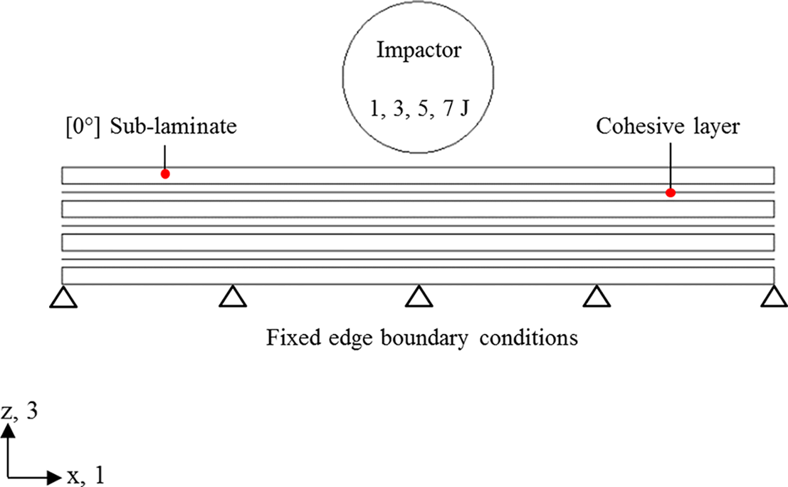
Schematic of the thermal–mechanical impact model.
Results
Impact testing
The results of the drop tower impact tests are presented in the following sections for slow- and fast-cooled laminates, respectively. The results show a general trend of increasing maximum impact force with impact energy reaching a maximum impact force of approximately 6 kN at 7 J.
Non-destructive inspection
Visual inspection of the slow-cooled and fast-cooled specimens post-impact showed a small indentation on the impact face attributed to the hemispherical impactor at all impact energy values. Application of the Toshiba Matrixeye™ NX 3D UT device showed a mixture of matrix failure, fibre breakage and ply delamination confined to a narrow area along the length of the specimens in the direction of the [0°] plys. The extent of delamination was shown to increase with increasing impact energy.
Simulations
Interlaminar failure and skin-core residual stress
The results of simulations which include interlaminar failure and skin-core residual stress only are presented in Figures 7 to 9. The maximum impact force is plotted in Figure 7 as a function of impact energy for slow-cooled and fast-cooled laminates and fast-cooled laminates with skin-core residual stress. The results show a general increase in maximum impact force with impact energy. Fast-cooled laminates were shown to have a higher maximum impact force than slow-cooled laminates at 3 J, 5 J and 7 J attributed to the difference in effective stiffness, critical strain energy release rate and extent of delamination. The fast-cooled results with skin-core residual stress were shown to be almost identical to the standard fast-cooled cases.
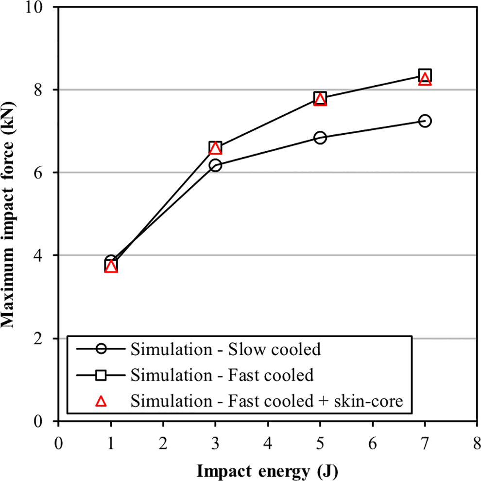
Simulation results with interlaminar failure only showing maximum impact force as a function of impact energy for slow-cooled, fast-cooled and fast-cooled laminates with skin-core residual stress.
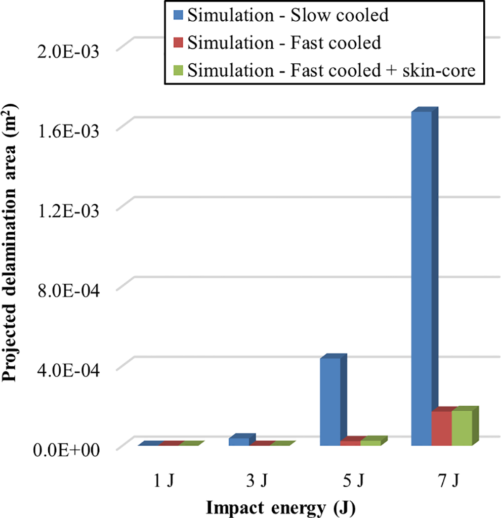
Simulation results with interlaminar failure only showing projected delamination area as a function of impact energy for slow-cooled, fast-cooled and fast-cooled laminates with skin-core residual stress.
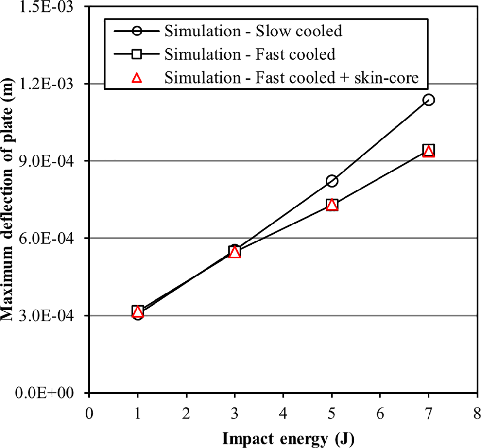
Simulation results with interlaminar failure only showing maximum plate deflection as a function of impact energy for slow-cooled, fast-cooled and fast-cooled laminates with skin-core residual stress.
The projected delamination area for slow-cooled and fast-cooled laminates and fast-cooled laminates with skin-core residual stress are presented as a function of impact energy in Figure 8. The projected delamination area is approximately zero for all cases with an impact energy of 1 J and 3 J. Slow-cooled laminates show a higher delamination area with increasing impact energy than fast-cooled laminates. This result is attributed primarily to the difference in critical strain energy release rate between slow- and fast-cooled laminates. The projected delamination in fast-cooled laminates with skin-core residual stress was shown to be almost identical to the standard fast-cooled cases.
The maximum deflection of the plate is plotted as a function of impact energy for all laminates in Figure 9. The results show an almost linear increase in maximum deflection with increasing impact energy. Slow-cooled laminates were shown to exhibit a higher degree of deflection than fast-cooled specimens at higher impact energy values. Similar to earlier results, fast-cooled specimens with skin-core residual stress were shown to be almost identical to the standard fast-cooled cases.
Interlaminar and intralaminar failure
The results of simulations which include both interlaminar and intralaminar failure are presented in Figures 10 to 15. These simulations exclude skin-core residual stress due to earlier findings which showed no significant difference in results between fast-cooled laminates and fast-cooled laminates with skin-core residual stress. The simulation results for maximum impact force in slow- and fast-cooled laminates are compared to the results of experiments in Figures 10 and 11, respectively. In the case of slow-cooled laminates, the simulation results show a similar trend to the experiment results of increasing maximum impact force with impact energy. The simulation results are shown to have a higher maximum impact force when compared to the experiments reaching a maximum of 26% at 3 J. At 7 J, the difference between the simulation and experiment result was approximately 1.2%. Similar to the results of experiments and simulations based on slow-cooled laminates, the maximum impact force in the fast-cooled simulations was shown to increase with increasing impact energy. The maximum impact force was also higher when compared to the experiments reaching a maximum of 29.5% at 5 J and a minimum of 6.9% at 7 J. The simulation results for fast-cooled laminates showed a higher maximum impact force than slow-cooled laminates attributed to the difference in effective stiffness, strain energy release rate and extent of delamination.
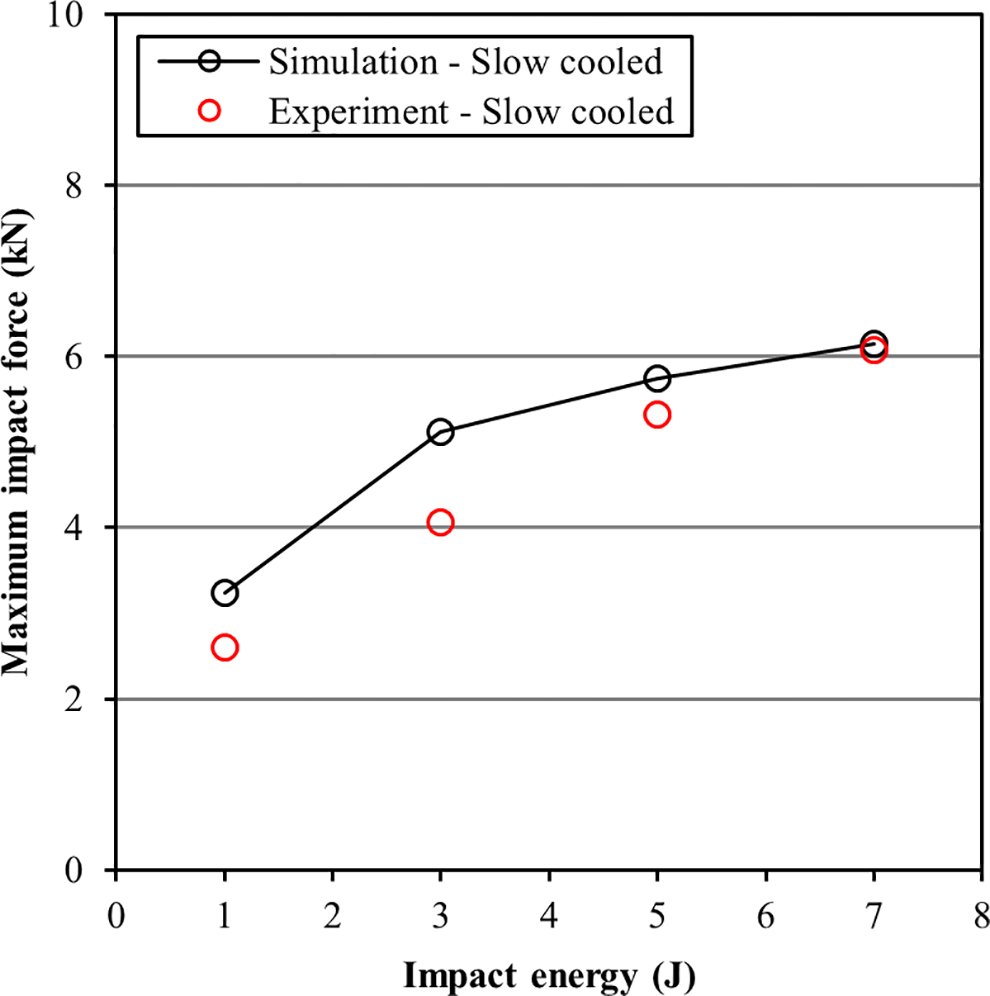
Comparison of simulation results including intralaminar failure and experiment results showing maximum impact force as a function of impact energy for slow-cooled laminates.
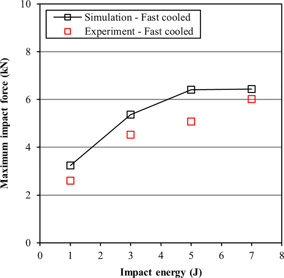
Comparison of simulation results including intralaminar failure and experiment results showing maximum impact force as a function of impact energy for fast-cooled laminates.
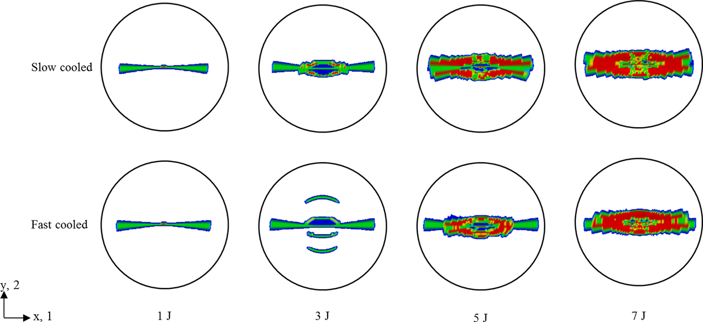
Simulation results showing intralaminar failure (red) of lowest sublaminate as a function of impact energy for slow-cooled and fast-cooled laminates.
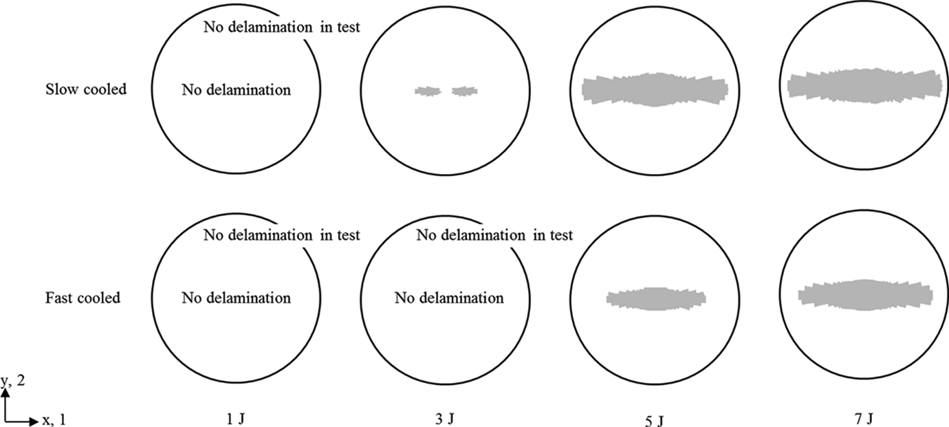
Simulation results including intralaminar failure showing interlaminar delamination (grey) of lowest sublaminate as a function of impact energy for slow-cooled and fast-cooled laminates.
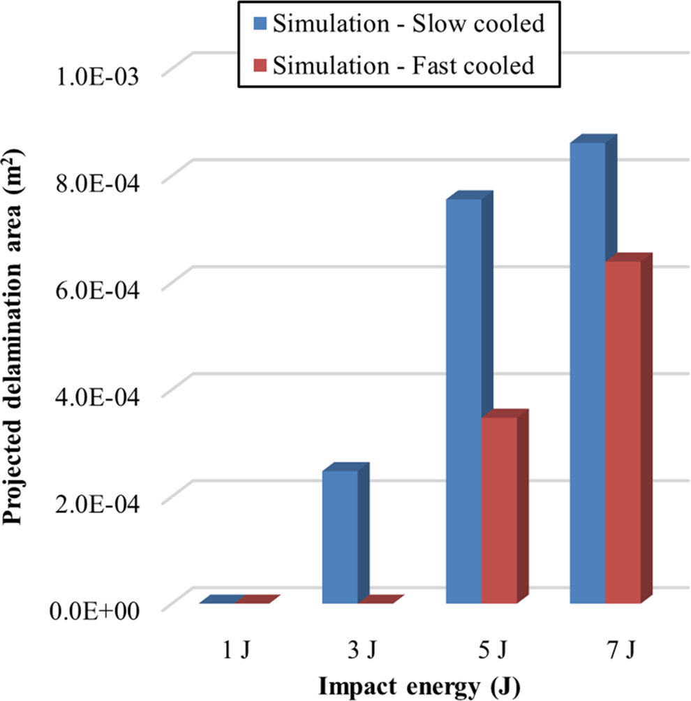
Simulation results including intralaminar failure showing projected delamination area as a function of impact energy for slow-cooled and fast-cooled laminates.
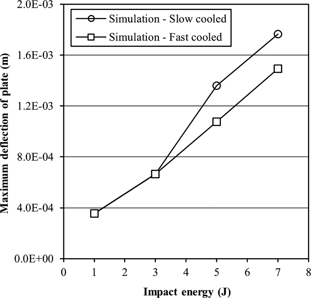
Simulation results including intralaminar failure showing maximum plate deflection as a function of impact energy for slow-cooled and fast-cooled laminates.
Simulation results showing the extent of intralaminar failure for slow- and fast-cooled laminates are presented in Figure 12. Intralaminar failure was not predicted in either slow- or fast-cooled laminates at the lowest impact energy 1 J. Failure was first predicted in the direction of the [0°] plys in the slow-cooled laminate at 3 J although no failure was predicted in the fast-cooled case. Further failure was then predicted at 5 J and 7 J in both the slow- and fast-cooled laminates in the direction of the [0°] plys. In all cases with intralaminar failure, the fast-cooled laminates showed a lower level of damage than the equivalent slow-cooled laminates.
Simulation results showing the extent of interlaminar delamination for slow- and fast-cooled laminates are presented in Figure 13. Delamination was not predicted in either slow- or fast-cooled laminates at the lowest impact energy 1 J. Small peanut-shaped delaminations in the direction of the [0°] plys were first predicted in the slow-cooled laminate at 3 J although no delamination was predicted in the fast-cooled case. Delamination was then predicted at 5 J and 7 J in both the slow- and fast-cooled laminates also in the direction of the [0°] plys. In all cases with delamination, the fast-cooled laminates showed a lower delamination area than the equivalent slow-cooled laminates. The lack of delamination at 3 J in the fast-cooled case and the smaller area of delamination when compared to the slow-cooled laminates at 5 J and 7 J was attributed to the faster cooling rate and the associated higher strain energy release rate. A bar chart showing the projected delamination area for slow- and fast-cooled laminates is presented in Figure 14.
The maximum deflection of the plate is plotted as a function of impact energy for slow- and fast-cooled laminates in Figure 15. The results show an increase in maximum deflection with increasing impact energy. Slow-cooled laminates were shown to exhibit a higher degree of deflection than fast-cooled specimens at higher impact energy values.
Discussion
The fast-cooled simulation results which included interlaminar failure only were shown to be almost identical in terms of maximum impact force and delamination extent to the fast-cooled simulations with skin-core residual stress. The magnitude of this skin-core residual stress was determined from separate simulations based on a UD lay-up sequence. It is possible that an alternative lay-up sequence, specimen thickness and/or faster cooling rate resulting in a higher skin-core residual stress may highlight a difference in maximum impact force and delamination extent to the standard fast-cooled case. The simulation results which included intralaminar and interlaminar failure were shown to improve the correlation with experiments in both slow- and fast-cooled cases. Although the inclusion of intralaminar failure reduced the predicted maximum impact force for all impact energy values, the magnitude of the maximum impact force in the simulation results was higher than experiments. This higher impact force may be attributed in part to the use of fixed boundary conditions applied at the edge of the model. A more compliant boundary condition similar to the actual experiments may have increased plate deflection and reduced the maximum impact force improving the correlation with experiments further.
The simulation results showed a higher magnitude of interlaminar delamination for slow-cooled specimens than fast-cooled at 3 J, 5 J and 7 J consistent with experiments and attributed to the higher strain energy release rate. Although the results of UT inspection indicated that the delamination was confined to a narrow area, the simulation results were shown to be in qualitative agreement with the ranking of delamination between the slow-cooled and fast-cooled specimens and the direction of delamination along the length of the [0°] plys.
Summary
This study investigates the influence of macroscale skin-core residual stress and cooling rate on the impact response of aerospace grade CF/PPS. Numerical simulations were developed which analyse the thermal shrinkage and residual stress development of UD lay-up configurations. Macroscale skin-core residual stresses were then incorporated into low-velocity impact simulations based on an orthotropic elastic material model. Interlaminar delamination was modelled using a bilinear cohesive traction–separation law, and intralaminar failure was modelled using the Chang–Chang strength-based failure criterion. The impact simulation results were compared with the results of drop tower impact tests showing qualitative agreement in terms of maximum impact force and delamination. Impact force was shown to increase with increasing impact energy for slow- and fast-cooled laminates. The simulation results of interlaminar delamination showed a general increase in delamination area with impact energy. Fast-cooled laminates were shown to have a lower delamination extent when compared to slow-cooled laminates attributed to the faster cooling rate and the associated higher strain energy release rate. The results of this work highlight the importance of cooling rate rather than skin-core residual stress on the impact response of CF/PPS. The influence of cooling rate on strain energy release rate indicates its potential role in controlling the intralaminar failure and interlaminar delamination of CF/PPS.
Footnotes
Acknowledgement
The author would like to thank Dr Takuhei Tsukada and Professor Nobuo Takeda for their support with this work.
Declaration of Conflicting Interests
The author(s) declared no potential conflict of interest with respect to the research, authorship and/or publication of this article.
Funding
The author(s) disclosed receipt of the following financial support for the research, authorship and/or publication of this article: This work was conducted at the University of Tokyo supported by JSPS KAKENHI, grant number 26220912.