
Abstract
Poly(vinylidene fluoride) (PVDF)-carbon nanotube (CNT) composites with three different CNTs were prepared by a solution blending and hot-press method. The morphologies of nanocomposites were studied by scanning electron microscopy. The X-ray diffraction and differential scanning calorimeter data indicated that the addition of CNTs can promote the formation of β-phase of PVDF. The dielectric constant values of three PVDF/CNTs are much greater than that of neat PVDF. It has been found that the dielectric loss of the short hydroxylated CNTs filled PVDF nanocomposite is lower than those of other two long pristine CNTs filled PVDF nanocomposites.
Introduction
High-dielectric-constant materials are highly desirable for use in a broad range of applications, such as electromechanical systems and charge-storage capacitors. 1,2 Polymer-based composite with excellent dielectric performance has been a very popular topic of research in material science receiving increasing attention in recent years. 3,4 Poly(vinylidene fluoride) (PVDF) has frequently been selected as the polymer matrix because of its piezoelectric and pyroelectric properties. For enhanced performances and expanded applications of PVDF, the large dielectric permittivity and/or high electrical conductivity are demanded. The traditional approach of enhancing their dielectric constants is to disperse high-dielectric-constant ceramic powder into the polymer matrix randomly. 5,6 However, polymer/ceramic composites have some disadvantages such as high mass density, more porous, and poor flexibility due to high concentration of inorganic fillers. Recently, carbon nanotube (CNTs) filled polymer composites have attracted much interest due to their high dielectric constant and good flexibility. CNTs can dramatically enhance the electrical, physical, and mechanical properties of polymer nanocomposites at extremely low loadings. 7 –9 It is worth noting that dispersion of nanoscale fillers is perhaps the most important issue in developing nanocomposites. For example, CNTs often get together in the form of agglomerates or ropes. The gaps within the agglomerate are generally too small to allow a complete infiltration of polymer to consolidate the CNTs. Without the surrounding matrix for load transfer, the CNTs agglomerate acts more like a void rather than a reinforcing element. Yao et al. 10 reported that the dielectric constant of multi-walled carbon nanotubes (MWCNT)/PVDF nanocomposites increased with an increase in the MWCNT aspect ratio. Further, the percolation threshold was inversely proportional to the length of the filler and increases with increasing filler aspect ratio. This fact was attributed to the MWCNT agglomeration that reduces the effective aspect ratio. For the purpose of controlling the filler dispersion and the matrix–filler interaction, some of the most interesting strategies were used including the functionalization of the fillers. Dang et al. 11 presented a value of 8000 for the dielectric constant of PVDF composite with 3,4,5 trifluorobromobenzene-modified MWCNT. It was found that the interfacial polarization is the main reason for the enhancement of the dielectric constant with the addition of MWCNT, which is higher for the functionalized MWCNT.
In the present study, three different CNTs, including long MWCNTs, long single-walled carbon nanotubes (SWCNTs), and short hydroxylated MWCNTs-OH filled PVDF nanocomposites were employed. Systematic reports on the influences of three different CNTs on structures, crystallization, frequency-dependent dielectric properties of PVDF-based nanocomposites with a certain CNTs contents (3.0 wt%) are given. X-ray diffraction (XRD) and differential scanning calorimeter (DSC) measurements confirmed the presence of β-phase in the nanocomposites at certain compositions. The morphologies of the nanocomposites were obtained by scanning electron microscopy (SEM) micrographs. The micrographs show the dispersion of fillers in the PVDF matrix. The studies of dielectric properties show that the MWCNTs-OH filled PVDF nanocomposites have higher dielectric constant and lower dielectric loss than the other two nanocomposites with MWCNTs and SWCNTs.
Experimental
Materials and sample preparation
The PVDF powder (FR 903, 3F Co. Ltd, Shanghai) with the melt index of 2.0 g/10 min was used. MWCNT with the average length of 5–15 μm and diameter of 40–60 nm, SWCNT with the average length of 5–15 μm and diameter of about 2 nm, and MWCNTs-OH with the average length of 1∼2 μm and diameter of 10∼20 nm were purchased from Shenzhen Nanotech Port Co., Ltd, which were synthesized by catalytic chemical vapor deposition (CVD) process. N,N-dimethylformamide (DMF) was purchased from Sinopharm Chemical Reagent Co., Ltd, China. All the chemicals were used as received.
Desired amount of PVDF polymer powder was dissolved in DMF and the predetermined amounts of CNTs (MWCNTs, SWCNTs, or MWCNTs-OH) were dispersed in DMF by applying ultrasonication for 50 min, respectively. Then, the suspension of CNTs in DMF was added into PVDF solution and ultrasonication was continued till the CNTs dispersed homogeneously in the polymer solution. Consequently, the mixture solution was dried at 80°C for 24 h to ensure the evaporation of all DMF solvents and then molded by hot pressing under 18 MPa at 180°C for 20 min and slowly cooled to room temperature under the pressure. The final samples with a disk shape were 12 mm in diameter and 1 mm in thickness. For electrical measurement, electrodes were painted with silver paste.
Characterization
The morphology of the PVDF/CNTs nanocomposites was characterized by SEM (HITACHI S-4800, Japan). All the samples were left in liquid nitrogen for 20 min and then cryogenically fractured to obtain a freshly fractured surface for SEM observation. This surface was gold sputtered prior to SEM observation. Crystalline structures of the neat PVDF and PVDF/CNTs nanocomposites were characterized with the aid of XRD (Bruker D8-Advance, Germany) using CuKα (n and then nm) radiation in the range of 2θ = 13° ∼ 29° at a scanning rate of 2°/min. Melting behavior of the neat PVDF and PVDF/CNTs nanocomposites was investigated with DSC (STA-449C, Germany). The samples were heated to 200°C at a rate of 10°C/min. Frequency-dependent dielectric constant of the neat PVDF and PVDF/CNTs nanocomposites was examined at room temperature by a Novocontrol TOP Class Dielectric Spectrometer with an Alpha-A high performance analyzer (DBS-80, Germany) in the frequency range of 102–107 Hz.
Results and discussion
Dispersion of CNTs in the PVDF matrix
To identify the dispersion state of three types of CNTs in the PVDF matrix, SEM images of fractured surfaces of the nanocomposites with 3.0 wt% CNTs are represented in Figure 1. Clearly, the morphologies of the three types of fillers are quite different from each other, and the differences are believed to be another critical factor that determines the filler–polymer interactions, as well as the dispersion in the polymer matrices. Due to the poor compatibility between pristine CNTs with polymer matrix, long MWCNTs and SWCNTs form very dense agglomerates in the PVDF matrix, as observed in the SEM images (as shown in Figure 1(a) and in the black circle of Figure 1(b)). In contrast, when short hydroxylated MWCNTs, MWCNTs-OH are used, the compatibility of fillers and PVDF is considerably improved and the MWCNTs-OH are homogeneously dispersed in the polymer matrix (as shown in Figure 1(c)). From Figure 1(a) and (b), one can observe that some MWCNTs and SWCNTs are pulled out on the fractured nanocomposite surface. However, most of MWCNTs-OH are embedded in the polymer matrix (Figure 1(c)). It is considered that the good combination is partly attributed to the strong hydrogen bond interaction between MWNTs-OH and PVDF. Interestingly, Figure 1(c) indicates that the diameter of MWCNTs-OH in the PVDF matrix is in the range of 50–60 nm in the black circle. This result indicates that the interfacial PVDF layer thickness is about 15–25 nm, by considering that the diameter of MWCNTs-OH used in this study is 10–20 nm. It supports the fact that the PVDF chains are well adhered on the MWCNT-OH surface.
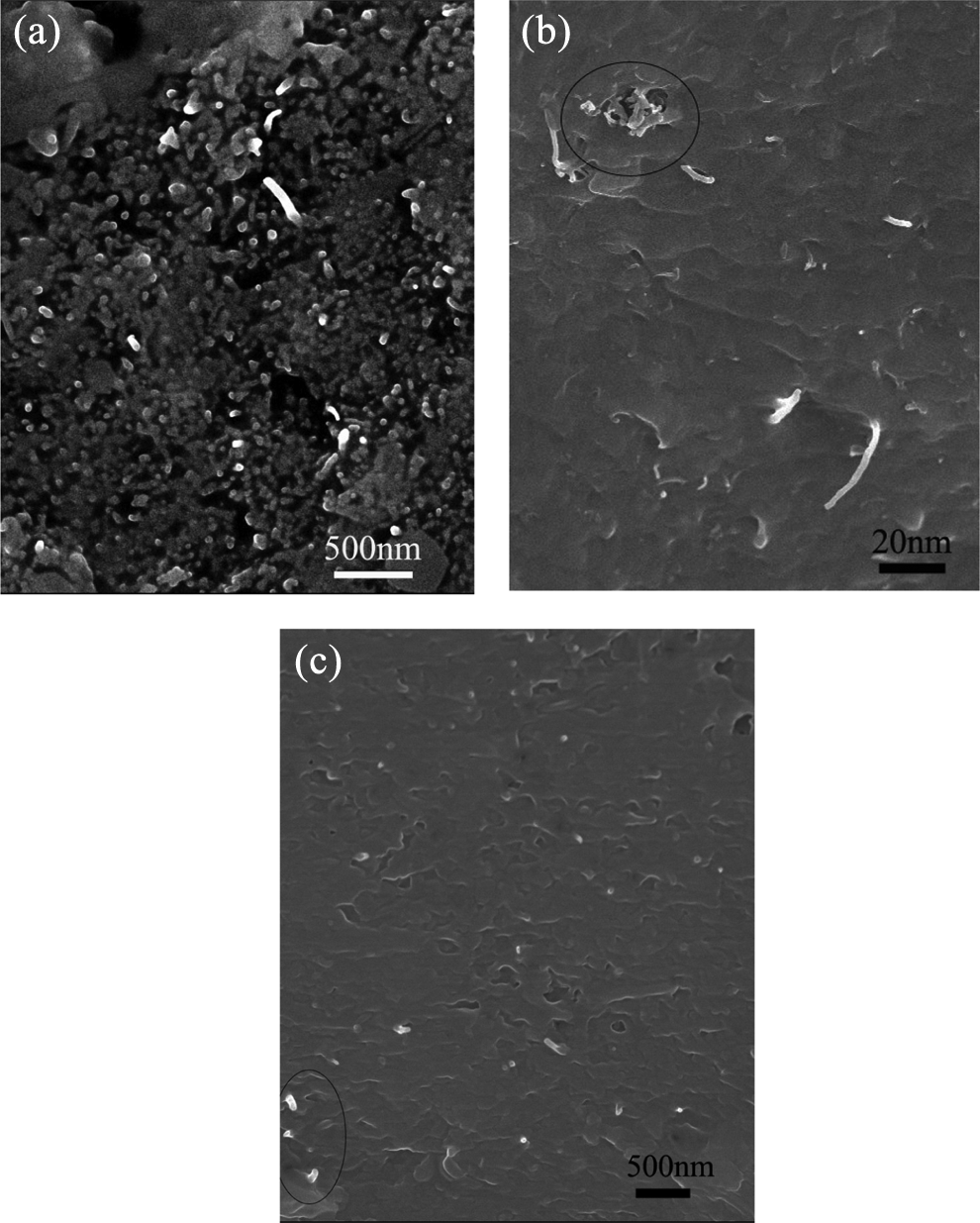
SEM images of PVDF/CNTs nanocomposites with 3.0 wt% (a) MWCNTs, (b) SWCNTs, and (c) MWCNTs-OH. CNT: carbon nanotube; MWCNT: multi-walled carbon nanotube; PVDF: poly(vinylidene fluoride); SEM: scanning electron microscopy; SWCNT: single-walled carbon nanotube.
Structure and melting behavior of the nanocomposites
Figure 2 shows XRD patterns of the neat PVDF and PVDF/CNTs nanocomposites with 3.0 wt% CNTs contents. It is well known that PVDF crystallizes in five different crystal forms that involve three different chain conformations such as TGTG′ for α- and δ-phases, all trans (TT) planar zigzag structure for β-phase, and TTTGTTTG′ for γ- and ε-phases. 12 –14 Among the five polymorphs, the β-phase has the largest spontaneous polarization per unit cell and thus exhibits the highest electroactive properties. γ-phase ranks second. There were many ways, such as crystallization from melt blending, the process of ultrasonication coupled with low-temperature-induced phase separation, or the presence of CNTs, not only introduced the β-phase in the powder form but also enhanced the amount of β-phase in most of the compositions. 15 –17 For the neat PVDF, strong diffraction peaks are detected at 2θ = 18.5o, 20.1o, and 26.8o, which correspond to 020, 100, and 021 reflections of PVDF α- and β-phase crystals, respectively (as shown in Figure 2(a)). When CNTs are added to PVDF, the diffraction peaks of α-phase at 2θ = 18.5o and 26.8o almost disappeared, indicating that the addition of small amount of CNTs can promote the molecules in PVDF to more regular, then resulting in increased crystallinity of PVDF, as shown in Figure 2(b) to (d). It has been recently found from the density functional theory calculation that, although both TGTG′ and all trans (TT) chains of PVDF are able to be absorbed on the CNT surface, the all trans (TT) molecular chain is bound on the CNT surface more tightly than the TGTG′ molecular chain does, and also the configuration in which H atoms and CNT surface are face-to-face is more stable than that where F atoms and CNT surface are face-to-face. 18 This suggests that the CNTs dispersed in the nanocomposites promote the overall β-phase crystallization of PVDF by serving as nucleating agents.
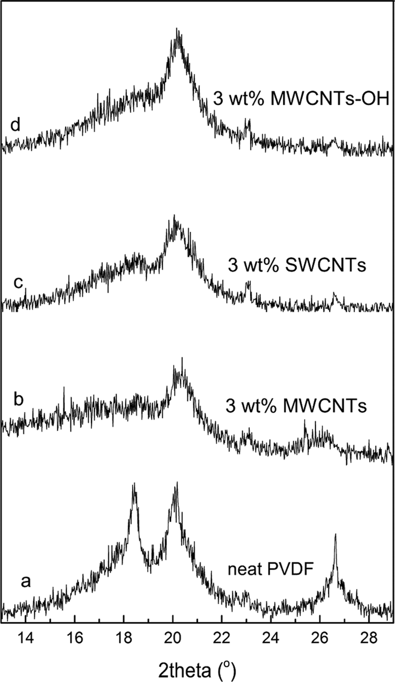
XRD patterns of (a) neat PVDF and PVDF/CNTs nanocomposites with (b) 3.0 wt% MWCNTs content, (c) 3.0 wt% SWCNTs content, and (d) 3.0 wt% MWCNTs-OH content. CNT: carbon nanotube; MWCNT: multi-walled carbon nanotube; PVDF: poly(vinylidene fluoride); SWCNT: single-walled carbon nanotube; XRD: X-ray diffraction.
DSC heating thermograms of neat PVDF and PVDF/CNTs nanocomposites with 3.0 wt% CNTs content are shown in Figure 3, and it is evident that the incorporation of CNTs in nanocomposites leads to higher melting peak temperatures compared with the neat PVDF. Neat PVDF has a melting temperature around 164.46°C (as shown in Figure 3(a)). It has been reported that the melting temperature of PVDF β-phase crystals is somewhat higher than that of PVDF α-phase crystals. 19 Therefore, it is considered that the higher melting temperatures of the nanocomposites with CNTs, compared with the neat PVDF (as shown in Figure 3(a)), are associated with the higher content of β-phase crystals existing in the nanocomposites. From Figure 3, it can be seen that the melting peak temperature shifts to considerably higher temperatures at 166.12°C (as shown in Figure 3(b)), 167.17°C (as shown in Figure 3(c)), and 167.84°C (as shown in Figure 3(d)) with the introduction of 3.0 wt% MWCNTs, SWCNTs, and MWCNTs-OH fillers, respectively. This clearly reflects the different heterogeneous nucleation contributions of MWCNTs, SWCNTs, and MWCNTs-OH to the host polymer, which is mainly ascribed to the dispersion state of the three fillers in the polymer matrix. Among three fillers, short MWCNTs-OH have the best dispersion state results in the greatest level adsorption of PVDF molecular chains, leading to a most efficient interaction between filler and polymer matrix, which is beneficial to heterogeneous nucleation. As for the melting peak temperature, maximal difference between neat PVDF and PVDF/MWCNTs-OH nanocomposite is observed.
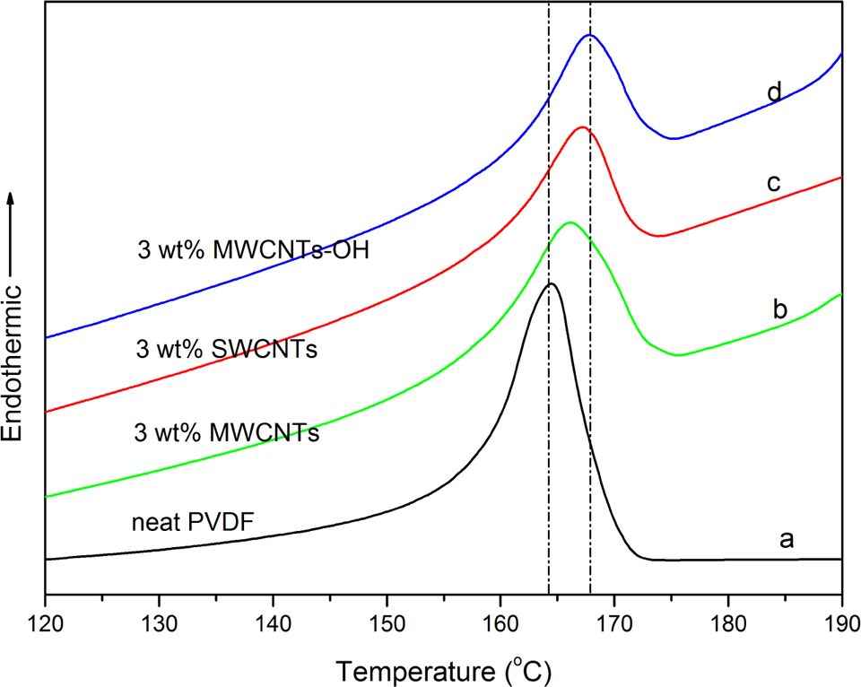
DSC thermograms of (a) neat PVDF and PVDF/CNTs nanocomposites with (b) 3.0 wt% MWCNTs content, (c) 3.0 wt% SWCNTs content, and (d) 3.0 wt% MWCNTs-OH content. CNT: carbon nanotube; DSC: differential scanning calorimeter; MWCNT: multi-walled carbon nanotube; PVDF: poly(vinylidene fluoride); SWCNT: single-walled carbon nanotube.
On the basis of the XRD and DSC results obtained in this study, it is valid to contend that, for the nanocomposites with CNTs, the all trans (TT) molecular chains of PVDF can be adsorbed favorably on the CNTs surface and thus CNTs act as nucleating agents for the formation of PVDF β-phase crystals during the crystallization process.
Figure 4 shows the dielectric constants of the neat PVDF and PVDF/CNTs nanocomposites with different CNTs as a function of frequency at room temperature. It is worth noting the large enhancement observed in the dielectric constants of the PVDF/CNTs nanocomposites. The attained values of the dielectric constants of the nanocomposites with 3.0 wt% MWCNTs, SWCNTs, and MWCNTs-OH fillers are 128, 246, and 381, respectively, at 102 Hz and room temperature. We found that the maximum dielectric constant obtained from PVDF/MWCNTs-OH nanocomposite was 381 at 102 Hz, which is approximately 35 times higher than the value for neat PVDF. The significant increment in dielectric constant of PVDF/MWCNTs-OH nanocomposite compared with neat PVDF can be mainly attributed to the homogeneous dispersion of short MWCNTs-OH in the polymer matrix and a formation of the microcapacitor networks in the PVDF/MWCNTs-OH nanocomposite. 20 In addition, Maxwell-Wagner-Sillars (MWS) polarization for heterogeneous systems plays a very important role in improving the dielectric constant. The MWS effect, which is associated with the entrapment of free charges between the insulator/conductor interfaces, can be characterized by the frequency dependence of the dielectric constant in the low-frequency range. In this way, charge carriers accumulate at internal interfaces because of the MWS effect. Perhaps, a heterogeneous system could be treated as many parallel or serial microcapacitors connected to each other. 21 This means that there were many MWCNTs-OH separated by very thin dielectric PVDF layers. Thus, a lot of charges were blocked at the interfaces between the filler and polymer matrix, owing to the MWS effect, which makes a remarkable contribution to the increment of the dielectric constant in the low-frequency range. Comparing the same weight fraction addition of long MWCNTs and SWCNTs, the volume content of SWCNTs is greater than that of MWCNTs in PVDF. Thus, PVDF/SWCNTs nanocomposite possesses more internal interfaces between the fillers and PVDF and higher dielectric constant than those of PVDF/MWCNTs nanocomposite.
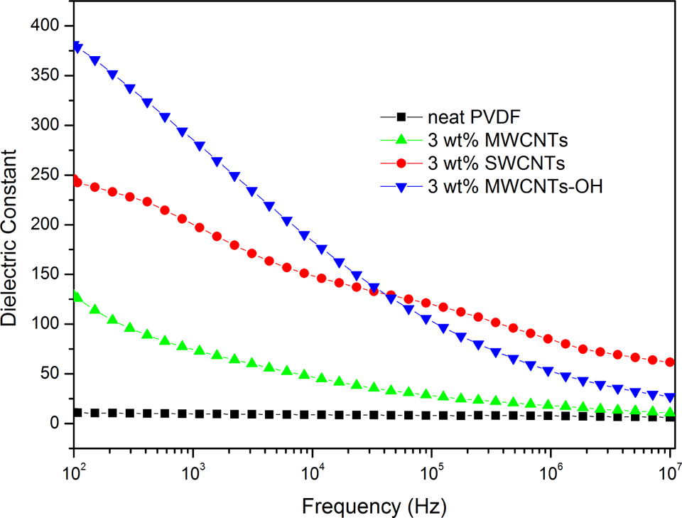
Dependence of the dielectric constants of neat PVDF and PVDF/CNTs nanocomposites on frequency at room temperature. CNT: carbon nanotube; PVDF: poly(vinylidene fluoride).
Figure 5 shows dielectric losses of neat PVDF and PVDF/CNTs nanocomposites at different frequencies. All PVDF/CNTs nanocomposites have higher dielectric loss than neat PVDF. The significant increment of dielectric loss of nanocomposites should be attributed to the filler agglomerates, which causes a dramatic increase of leakage currents. As shown in Figure 5, the nanocomposites have the same weight fraction of fillers but exhibit visibly different dielectric loss. The attained value of the dielectric losses of the nanocomposites with 3.0 wt% MWCNTs, SWCNTs, and MWCNTs-OH fillers are 1.85, 4.14, and 0.15, respectively, at 102 Hz and room temperature. Among the three nanocomposites, conductive network is easiest to form in the long SWCNTs filled nanocomposites, which result in a significant increase in the conduction loss. The dielectric loss of the nanocomposite with 3.0 wt% short MWCNTs-OH is significantly lower than those of other two nanocomposites, which reveals that the dispersion state of MWCNT-OH in nanocomposites is assuredly better.
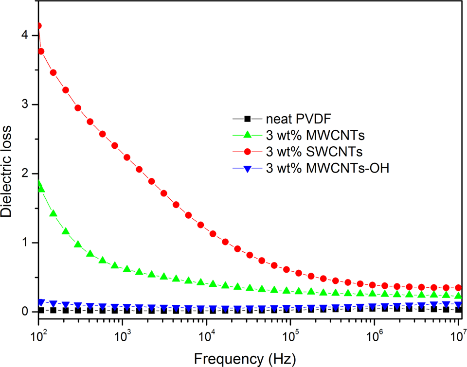
Dependence of the dielectric losses of neat PVDF and PVDF/CNTs nanocomposites on frequency at room temperature. CNT: carbon nanotube; PVDF: poly(vinylidene fluoride).
Conclusions
In this study, three types of PVDF/CNTs nanocomposites with short MWCNTs-OH, long MWCNTs, and SWCNTs were manufactured by the ultrasonication-based solution blending and hot-press method. Morphological features, structures, melting behavior, and dielectric properties were investigated. SEM images of nanocomposites confirmed that MWCNTs-OH were dispersed uniformly in the polymer matrix by wrapping with PVDF chains. XRD patterns and DSC heating thermograms demonstrated that three types of CNTs promoted the formation of PVDF β-phase crystals. It was also found that the frequency-dependent dielectric constants and dielectric losses of the nanocomposites were strongly dependent on the dispersion state of CNTs in the polymer matrix.
Footnotes
Declaration of Conflicting Interests
The author(s) declared no potential conflicts of interest with respect to the research, authorship, and/or publication of this article.
Funding
The author(s) disclosed receipt of the following financial support for the research, authorship, and/or publication of this article: The authors acknowledge the financial support provided by the National Natural Science Foundation of China (No. 51607109, 51476094, and 51590901), the Natural Science Foundation of Shanghai (No. 15ZR1417100, 16ZR1412400), the Popular Science Propaganda on Innovation, and entrepreneurship for college students—new energy and new materials (No. 16DZ2348700).