
Abstract
Currently, polymeric insulation materials are widely used for energy saving in buildings. Despite of all benefits, these materials are generally sensitive to heat and highly flammable. This work discusses possibility to improve heat resistance of expanded polystyrene (EPS) foam using thin silicon dioxide (SiO2) films deposited by magnetron sputtering technique. In order to increase surface energy and adherence of SiO2 thin films to substrate EPS was plasma pretreated before films’ depositions using pulsed DC plasma generator for 40 s in argon gas. SiO2 formation was done in reactive argon and oxygen gas atmosphere. Laboratory made equipment was used for flame torch–induced heat resistance experiments. Results showed that silicon oxide films remains stable during heat resistance experiments up to 5 s and fully protects polystyrene (PS) substrate. Films are relatively stable for 30 s and 60 s and partially protect PS from melting and ignition. Scanning electron microscopy, energy-dispersive X-ray spectroscopy, and X-ray photoelectron spectroscopy analysis confirmed that SiO2 layer, which is distributed uniformly on the EPS surface, could work as a good heat resistant material.
Introduction
Wide usage of expanded polystyrene (EPS) foam for energy saving in buildings is driven by its low cost, low weight, easy processing, and excellent energy conservation properties. However, EPS is highly sensitive to heat, flammable, and, in case of fire, smoke and toxic gasses are produced. 1,2 The association of European Manufacturers of Expanded Polystyrene recognizes the importance of behavior of EPS in case of fire and affirms that EPS material can be readily ignited by its exposure to direct flame. Accordingly, care should be taken to avoid contact with sources of ignition when handling and storing EPS material before and after installation. 3 –5 During the exposure to flame and heating process, polystyrene (PS) overcomes certain changes: it softens as it approaches the melting point of 160°C; up until about 275°C, the molten high molecular weight polymer remains stable; above 470°C, however, thermal decomposition produces lower molecular weight fragments that are easily volatilized, thus completing the decomposition. 6,7 It has been also experimentally observed that the rate of molecular weight decrease is very high at the initial stages of the reaction and slower at later stages, accompanied by the evaporation of the low-molecular weight fragments. 8 Improving the fire retardant behavior would lead to the extended usage of EPS and similar materials in lots of applications. 9,10 There are two main options to increase fire retardant properties of polymer materials: to introduce functional groups onto the polymer surface 11,12 or to deposit different coatings using methods such as plasma polymerization, 13 spray or electrospray coatings, 14 and so on. Fire retardant materials can be described as chemical compounds that modify oxidation or pyrolysis reactions of polymers implied in the combustion by slowing down or by inhibiting them. 15 Also, retardants can retard the ignition and/or decrease flame spreading physically by cooling, formation of a protective layer, or chemically by reactions in condensed or gas phase. 16,17 There is wide variety of flame retardant materials which can be used with polymer materials in order to increase their fire resistance performance. Ammonium polyphosphate, pentaerythritol and melamine, 18 graphene, 19 polystyrene/montmorillonite nanocomposite films, 20 and various types of carbon nanomaterials 21 were used as flame retardant materials which improved the thermal stability and essentially reduced PS flammability. Recent works presented by Attia et al. 22 showed that high-purity silica particles produced from agricultural waste materials, rice husk, which was used in conjunction with diammonium hydrogen orthophosphate and multiwalled carbon nanotubes (MWCNTs) lead to 71% reduction of PS composites flammability. Rise husk silica also was used to enhance thermal stability of other polymeric materials such as acrylonitrile-butadiene-styrene (ABS), 23 epoxy composites, 24 and others. Various types of silica, silica gel, fumed silica, and fused silica were used as flame retardants in polypropylene, 25 polyethylene oxide, 26 and poly(methyl methacrylate) (PMMA) 27 samples. The reduction of flammability properties were observed in most of the cases and viscosity control proved to be a key factor in formation of the protective layer. 27
In this work, we report the synthesis of silica protective layer using magnetron sputtering of silica (Si) in reactive argon and oxygen environment. The effects of surface morphology, elemental, and chemical composition to the thermal stability of coated EPS have been investigated.
Experimental
Silicon dioxide (SiO2) thin films were deposited on EPS foam using magnetron sputtering system. The nominal density of EPS foam used is ρ ≈ 22 kg m−3 (type II EPS based on ASTM C 578-10 standard). The foam was cut into small pieces of 20 × 30 × 10 mm3. The system was equipped with magnetron using 99.99% purity Si target obtained from Kurt J. Lesker Company (United Kingdom). Plasma pretreatment of substrate material was used in order to increase film adherence to substrate (Figure 1).
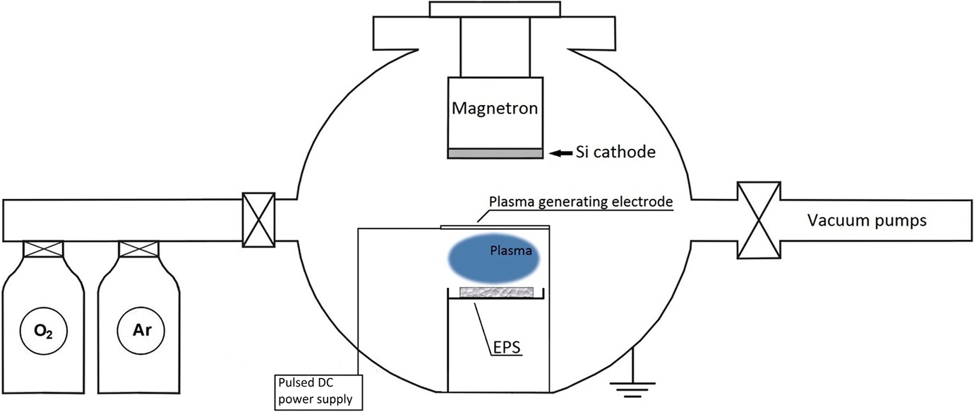
Scheme for the plasma pretreatment of EPS samples and SiO2 film deposition. EPS: expanded polystyrene; SiO2: silicon dioxide.
Plasma pretreatment was done using pulsed DC generator with 20 kHz frequency and 110 W power. The distance between samples and plasma cathode was 40 mm. The plasma pretreatment of substrates was done at 10 Pa pressure in Ar (industrial gas provider: AGA Gas AB, A member of the Linde group; 99,999% purity) gas atmosphere for 40 s. The deposition of SiO2 thin films was done without extraction of plasma-activated EPS substrates to the atmosphere. Thin film deposition procedures were performed at room temperature. Pulsed DC magnetrons sputtering of Si in reactive atmosphere (Ar—80% ÷ O2—20%) was used for film deposition. Magnetron power during film deposition was 140 W, and the distance between EPS substrate and Si cathode was 40 mm. Due to high sensitivity of EPS to high temperature, the deposition process was split in eight steps: (5 min of deposition + 5 min of cooling) × 8 times.
The obtained coated EPS samples were extracted from the chamber to atmosphere and characterized using various techniques before and after the heat impact test procedures. For surface morphology characterization, we used scanning electron microscope Hitachi S-3400N (Hitachi High-Technologies Corporation, Japan). Elemental concentrations and their distribution were analyzed using energy-dispersive X-ray spectrometer Bruker Quad 5040 (Bruker-AXS Microanalysis GmbH, Germany). X-ray photoelectron spectrometer is a powerful tool which can be used for the identification of the chemical state/phase of elements and compounds regardless of their crystallinity. Also, this method could be suitable in order to understand PS or other polymers thermal degradation process. 28,29 Considering the relatively small thickness of the as deposited SiO2 films and its distribution at EPS surface chemical phase, the stoichiometry of the films was determined by X-ray photoelectron spectrometer PHI 5000 Versaprobe (ULVAC-PHI, INC., Japan). In order to check if SiO2 film reacts with EPS substrate or remains inert, we also used the same method to analyze the chemical state of the Si and O atoms after the heat treatment experiments. Main XPS parameters were as follows: monochromated 1486.6 eV Al radiation, 25 W beam power, 100 μm beam size, and 45° measurement angle. Spectral window of each element was recorded with 0.1–0.2 eV step for 20–35 eV window (depending from element). The energy throughput window at the detector for each element was 23.5 eV. Sample charging was compensated by using dual neutralization system consisting of low-energy electron beam and ion beam. Energy scale calibration was performed with Cu2p and Au4f peaks, meanwhile, charge compensation was done by measuring C1s peak of anthropogenic carbon and fixing it at 284.8 eV.
The main methods used to evaluate material flammability are limiting oxygen index and UL-94 tests. These techniques require direct contact between samples and flame. 30,31 However, EPS in direct contact with flame melts rapidly, and the detailed analysis of EPS degradation would be very complicated even for EPS with SiO2 layer. Therefore, a well-controlled experimental testing setup presented in Figure 2 was designed for the heat impact tests of coated and uncoated EPS samples.
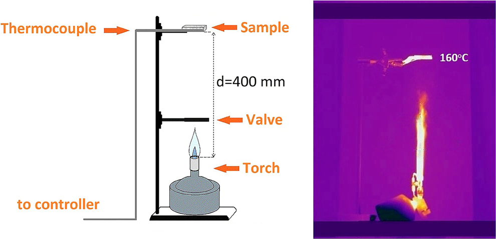
Experimental setup for the heat impact test: schematic picture (left) and thermovision capture in experiment time (right).
Main components of the setup are stand with sample holder, gas burner (PG 200, manufactured by Providus technics, Italy) using butane–propane mixture gas cartridge CG190, flame torch shield, and K-type thermocouple mounted in the sample zone. Distance between burner head and tested sample surface was 400 mm. The size and intensity of the flame was adjusted to obtain an equilibrium temperature in the sample zone to be equal to 160 ± 2.5°C. Visible length of the torch was approximately 200 mm. Before performing tests, the burner was preburned for 5–10 min and adjusted to obtain stable torch and temperature in the sample zone. Heat impact tests were started rapidly removing and stopped by rapidly returning 150 mm wide flame shield.
Results and discussions
SiO2 thin film on EPS samples deposited in magnetron sputtering system was extracted to atmospheric air and characterized using scanning electron microscopy (SEM)+energy-dispersive X-ray spectroscopy (EDS) and XPS techniques before and after expose to flame torch–induced heat.
In order to determine the changes in SiO2 thin film thickness, cross-section measurements were done for the samples before and after expose to flame torch–induced heat (Figure 3).
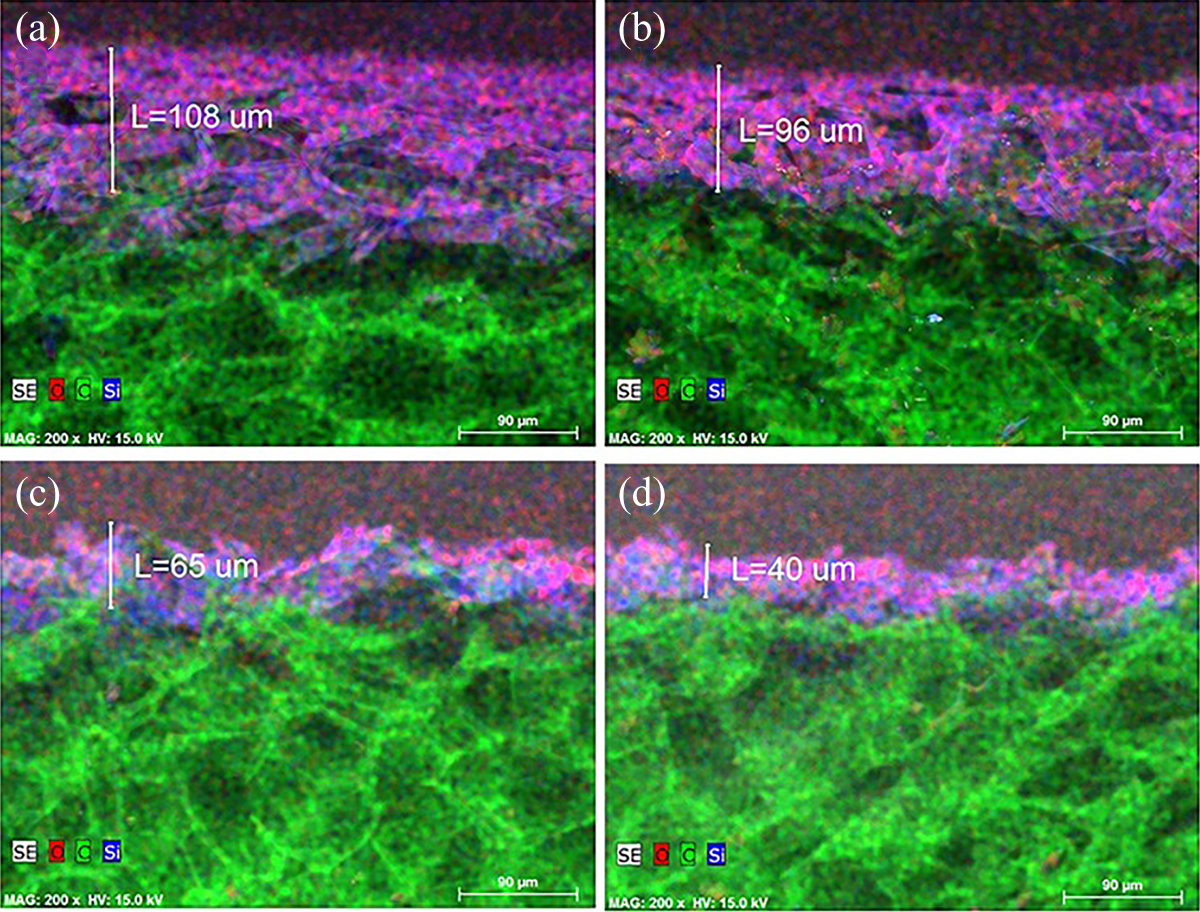
EPS with SiO2 thin film cross-section measurements: (a) before flame torch–induced heat, (b) after 5 s, (c) after 30 s, and (d) after 60 s of flame torch–induced heat. EPS: expanded polystyrene; SiO2: silicon dioxide.
It is seen that there is no clear boundary line between SiO2 thin film and EPS substrate. SiO2 penetrates into subsurface region of EPS, mixes with it, and forms nonuniform altered layer consisting from film and substrate materials. The penetration of SiO2 particles could be described by several processes. Generally, during solid particles deposition on solid substrates surface, they are stopped and particles’ kinetic energy becomes thermal energy which heats up the surface of substrate. However, EPS foam is relatively soft, porous, and highly sensitive to heating material. Because of it, SiO2 particles were not stopped immediately, but penetrate into subsurface region. It can be expected that part of arriving particles kinetic energy transforms to thermal energy and heats up EPS surface. 32,33 It would also lead to prolonged penetration depths of arriving SiO2 particles. SEM analysis also revealed that altered layer consists of difference in size clusters. The thickness of altered layer after deposition was estimated 108 µm (Figure 3 (a)). It decreased to roughly 96 µm after 5 s (Figure 3 (b)), roughly 65 µm after 30 s (Figure 3 (c)), and to roughly 40 µm after 60 s treatment (Figure 3 (d)) in flame torch–induced heat. The loss of the SiO2 film could be explained due to extreme difference in thermal expansion of EPS which is α = 5 − 7 × 10⁻⁵°C−1 34 and for SiO2—α = 0.5 × 10⁻⁶°C−1 35 and it leads to formation of high stresses in the altered layer structure which causes peeling effects of SiO2 material and decrease in altered layer thickness.
Noncoated EPS surface morphology view revealed cellular structure (Figure 4 (a)) which remains similar after SiO2 thin film deposition (Figure 4 (b)). It is seen that SiO2 thin film replicated EPS surface morphology. Figure 4 (c) represents surface morphology of noncoated EPS surface after treatment by direct flame torch–induced heat for 5 s. The noncoated surface shows clear signs of degradation. Cellular-like structure partially disappeared and some of parts of the surface become melted, big (more than 100 µm diameter) open holes appeared. At the same time, EPS surface protected by SiO2 film shows no signs of degradation (Figure 4 (d)) and remains similar to the as coated sample (Figure 4 (b)). After direct flame torch–induced heat treatment for 30 s, the noncoated EPS surface material continues to melt (Figure 4 (e)), the number of holes appeared, and holes’ diameter increases. Most of the SiO2-coated EPS surface remains well protected (Figure 3 (c)) but surface parts were SiO2 film erupted from the surface also appeared (Figure 4 (f)). The areas without SiO2 film show similar behavior as in noncoated one: EPS structures melt and formation of holes could be observed. Surface material melting and SiO2 film eruption become more evident with the increase of flame torch–induced heating time up to 60 s (Figure 4 (g) and (h)).
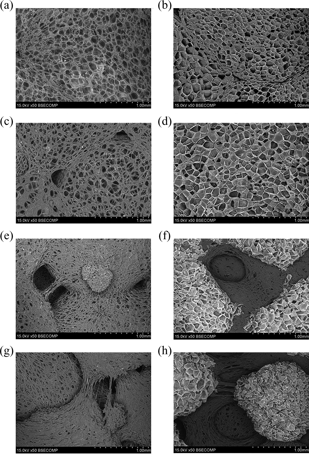
SEM images of flame torch–induced heat-untreated EPS surface without and with SiO2 thin film (a and b), EPS surface without and with SiO2 thin film after flame torch–induced heat experiments for different durations: 5 s (c and d), 30 s (e and f), and 60 s (g and h). SEM: scanning electron microscopy; EPS: expanded polystyrene; SiO2: silicon dioxide.
The EDS mapping images of EPS samples coated by SiO2 films represent heat-untreated EPS samples (Figure 5 (a)), and the corresponding heat-treated (for 5 s) samples (Figure 5 (b)) reveal uniform structures as no island-like features are present. Flame torch–induced heat-treated samples for 30 s (Figure 5 (c)) and 60 s (Figure 5 (d)) show island-like structures consisting of SiO2-coated EPS surrounded by degraded polymer without SiO2 layer. The dimensions of SiO2 structures decreased with the increase of heat treatment time, and it confirms results represented in Figure 4 (f) to (h).
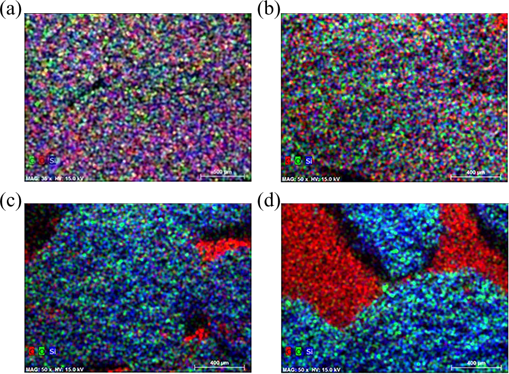
EDS mapping of SiO2-coated and heat-untreated sample (a), SiO2-coated and heat-treated sample for 5 s (b), SiO2-coated and heat-treated sample for 30 s (c), and SiO2-coated and heat-treated sample for 60 s (d). Blue color represents silicon, green—oxygen, and red—carbon. EDS: energy-dispersive X-ray spectroscopy; SiO2: silicon dioxide.
We performed detailed XPS analysis of our samples in order to understand how SiO2 thin film is changed during flame torch–induced heat treatment experiments for the longer treatment time (30 s and 60 s). O1s and Si2p XPS spectra of as-deposited and heat-treated samples are presented in Figure 6.
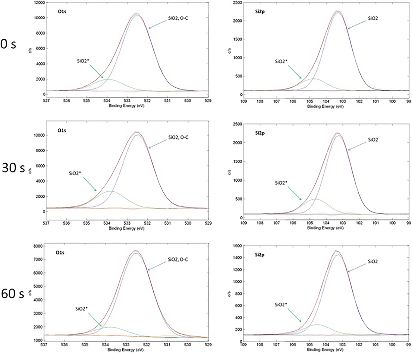
O1s and Si2p XPS spectra for the as-deposited (0 s) SiO2 film and SiO2 coatings after different duration of heat treatment test (30 s and 60 s). XPS: X-ray photoelectron spectroscopy.
First of all, it can be noted that after 30 s and 60 s of flame torch–induced heat test, O1s and Si2p spectra remained nearly the same as they were in the as-deposited state indicating that SiO2 coatings remain chemically stable during heat test. Deconvolution of observed spectra shows up that all observed peaks consist of two main components. Dominant component of O1s spectra has binding energy of 532.5 eV and can be attributed to SiO2 and C–O bonds, whereas dominant component of Si2p spectra has binding energy of 103.3 eV and is also assigned to SiO2 phase. Higher binding energy components of O1s and Si2p spectra are placed at roughly 533.8–534 eV and 104.6–104.8 eV, respectively. In order to better understand the origin of these higher binding energy peaks, we compared the binding energy difference (ΔBE) and area ratios (calculated as a low binding energy peak fraction from whole peak area) of the corresponding deconvoluted O1s and Si2p peaks (Table 1).
Comparison of binding energy difference (ΔBE) and area ratios of the corresponding deconvoluted O1s and Si2p peaks.
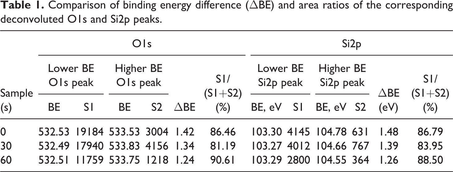
It was observed that for the same sample, there is correlation between binding energy difference and fractional area of deconvoluted O1s and Si2p spectra components. Full width at half maximum (FWHM) values are also nearly similar for all peaks (1.7 eV for O1s and 1.8 eV for Si2p). Accordingly, this can be interpreted as the existence of several domains with different steady-state charge which leads to the different binding energy reading for the same SiO2 compound. The origin of these domains could be attributed to the different conductivity of EPS, SiO2 coating, and EPS–SiO2 interface.
Conclusions
An increase in thermal stability and the reduction of flammability of EPS foam remains as one of the main challenges for the extending its applicability in variety of applications. SiO2 thin films produced by magnetron sputtering were used in order to protect EPS material surface from direct flame torch–induced heat. SEM and EDS analysis revealed formation of altered layer consisting of SiO2 and EPS materials after SiO2 film deposition. Due to heating effects during films deposition, no clear boundaries between SiO2 film and EPS substrate were observed. It was shown that SiO2 helps to reach better heat resistance properties compared to noncoated EPS. Coated EPS can withstand flame torch–induced heat for 5 s without significant losses. Unfortunately with the increase of the expose time to flame torch–induced heat from 20 s to 60 s peeling effects of SiO2 material were revealed and decrease in altered layer thickness from initial 104 µm to 65 µm and 40 µm were observed. It also leads to the formation of noncoated islands on EPS surface which tends to dominate with the increase in direct heat treatment time. XPS measurements results showed that SiO2 coatings remain chemically stable during direct flame torch–induced heat tests and remain on the EPS surface.
Footnotes
Declaration of Conflicting Interests
The author(s) declared no potential conflicts of interest with respect to the research, authorship, and/or publication of this article.
Funding
The author(s) disclosed receipt of the following financial support for the research, authorship, and/or publication of this article: This work was financially supported by The European Social Fund under project with SFMIS code: VP1-3.1-SMM-10-V-02-019.