
Abstract
There are increasing interests in using thermoplastics to replace thermosets to laminate fabrication due to their advantages such as high toughness, shorter manufacturing cycles, and reprocessing possibilities. The aim of the current study is to select appropriate thermoplastic nanocomposites, which fit the requirements of carbon fiber (CF) composites in the automotive industry. In order to achieve the target, this research has investigated the effect of nanoclay on the mechanical, thermal, and interfacial properties with de-sized CF of polyamide (PA6) composites. PA6/clay composites were characterized by different properties, namely, bending, tensile, impact, heat distortion temperature, interfacial shear stress, and scanning electron microscope. The micromechanism of plastic deformation after bending failure of PA6-clay nanocomposites is examined with different contents of nanoclay to correlate the microstructures with the mechanical properties. The results revealed that with 3% organo-clay filler content, flexural strength and modulus improved significantly by 42% and 52%, respectively, which could be explained by scanning electron microscopy images that show rougher fracture surface with adding clay into the PA6 matrix. The increased surface roughness implies that the path of the crack tip is distorted because of the silicate nano-layer, making crack propagation more difficult. The interfacial shear strength for 1 wt% of nanoclay was about the same as the neat PA6 but decrease dramatically with increasing contents of nanoclay.
Introduction
In the past decade, research on the preparation and characterization of organic–inorganic nanocomposites have attracted much academic and industrial attention. Numerous research efforts in this field have focused on the incorporation of nano-fillers to greatly enhance their physical, mechanical, and chemical properties in various polymer matrices, including epoxy, polypropylene, polyethylene, polyimide, polystyrene, poly(methyl methacrylate), and so on. 1 –5 Most research results revealed a great improvement in polymer properties by addition of a small amount of nano-filler (<5 wt%). Important factors that can affect the physical and mechanical properties of nano-filler-reinforced polymer nanocomposites include nano-filler type, filler loading levels, and processing. 6 Nanoclay, an inexpensive natural mineral, has been reported by many studies as the one of the potential candidates for nanocomposite and Carbon Fiber Reinforced Plastics (CFRP) composites because of its large value of aspect ratio, diameter in nanometer range, and thermal resistivity. 7 Vlasveld et al. 8 reported that in most cases, in order to provide a better physical and chemical environment for the polymer, clay is organically modified through an ion exchange reaction between organic cations and inorganic cations, so that hydrophilic clay becomes organophilic, increasing the interlayer spacing of clay. Among the nanocomposites investigated, polymer/clay (silicate) systems exhibited great promise in industrial applications due to their potential to display synergistically advanced properties with only minor amounts such as 3–5 wt% of clay loadings. The properties that could be enhanced by adding nanoclay include tensile/flexural strength, heat distortion temperature (HDT), thermal stability, flame retardancy, and barrier property. The successful pioneering work on these nanocomposites was conducted on the polyamide 6 (PA 6)/montmorillonite (MMT) clay system by Toyota company. 9 Since then, the anticipated versatile applications have led to vigorous researches on other polymer/clay nanocomposite systems, in which the polymeric matrix such as polyolefins, epoxy, polyesters, PAs, styrenic polymers, polyurethanes, 9 –12 and so on. Mohan and Kanny 13 reported that nanoclay has ability to improve the fracture strength and wear properties of short-fiber-reinforced thermoplastics polypropylene composites. Silica and alumina nanoparticles also showed positive effects with respect to the mechanical properties of thermosetting composites. 14,15 Vlasveld et al. 7 reported that the flexural strength of glass/PA6 composites increased because of the improved stiffness of the matrix, with the addition of a nano-filler. On the other hand, Vlassveld et al. in another article 8 found that exfoliated and layered silicate has a negative effect on the bonding between glass fibers and PA6 nanocomposites. Isitman et al. 16,17 also confirmed that nano-fillers reduced the interfacial shear strength (IFSS) of composites.
Recently, there has been an increasing interest in using thermoplastics to replace thermosets to laminate fabrication such as carbon fiber (CF) composites due to several advantages such as high toughness, shorter manufacturing cycles, no refrigeration storage required, and reprocessing possibilities. 18 The CF-reinforced composites are widely used in aerospace, marine, and automobile industries due to their outstanding properties such as high specific strength and stiffness, lower density, and flexible designs. 19 –23 Properties of composites not only are determined by the CF, the resin matrix but also are influenced by the interphase formed between the two constituents. 24 Favorable interfacial adhesion can efficiently transfer stress from matrix to the fibers, playing a key role in determining the mechanical performance of the composites as well as the reliability. To the best of our knowledge, the influence of clay system on the de-sized CF/matrix interfacial adhesion has not been studied yet. The aim of the current work is to examine the micromechanism of plastic deformation during bending loading of PA-clay nanocomposites and to compare with the unreinforced PA under identical conditions of processing to underscore the determining role of clay. Another important goal from the viewpoint of CF-reinforced thermoplastic industry is to measure the interfacial strength of the de-sized CF with PA/clay composites. Different weight percentages of Nanomer® I-30E nanoclay were dispersed in PA6 using a melt mixing method followed by injection molding. PA/clay composites were characterized by different properties, namely, bending, tensile, impact, heat distortion temperature (HDT), and interfacial shear stress.
Experiments
Materials
PA (cm1006 with MFR 15 g 10 min−1 at 230°C) was purchased from Toray Co., Tokyo, Japan; MMT clay, Nanomer I.30E, containing 25–30 wt% octadecylamine with bulk density 200–500 kg m−3 were purchased from Sigma Aldrich, Tokyo, Japan.
Preparation of PA6/clay Nanocomposite
PA6/clay masterbatch with 10 wt% clay was obtained by melt blending using a kneading twin-screw extrusion machine (NT-16-29, Musashino Co., Tokyo, Japan) at 250°C and 100 rpm. The masterbatch pellets were mixed with specified contents of clay into the twin-screw extruder machine in order to receive the nanocomposites with various contents 1, 2, and 3 wt% clay. The pellets were dried at 80°C for 48 h, then samples were fabricated using hand-truder injection machine. Injection temperature was 245°C, and the mold temperature was 90°C.
Characterization
Structure characterization
A differential scanning calorimetry (DSC-8500) apparatus made by PerkinElmer Inc.- Tokyo, Japan - was used for investigating the crystallization process of PA6 and PA6/clay nanocomposites. About 11 mg of the polymer sample was weighed accurately in the aluminum DSC pan and placed in the DSC cell. The sample was heated from 50°C to 250°C and held for 5 min at 250°C to eliminate the previous heat history completely before cooling to 50°C at a constant rate of 10°C min−1. All measurements were carried out in room temperature and heat flow curve was recorded as a function of temperature.
Flexural properties
Flexural tests under three-point bending configuration were performed according to ASTM D790-86. The tests were conducted in a 5-kN servo hydraulic testing machine equipped with Test Ware data-acquisition system (Shimadzu Co., Tokyo, Japan), which was run under displacement control mode at a crosshead speed of 2.0 mm min−1. The specimens with dimensions of 80 mm long × 10 mm wide × 4 mm thick were loaded until failure with a support span of 64 mm.
Tensile Tests of PA6/clay nanocomposites
The tensile tests for PA6/clay nanocomposites were carried out using universal testing machine (5kN; Shimadzu) at a crosshead speed of 1 mm min−1 at room temperature according to ASTM D638. Five samples of each category were tested in room temperature and their average values were reported.
Impact Properties
Charpy impact test was carried out on a CEAST 9050/DAS 64S (Instron Co., Tokyo, Japan) pendulum impact testing machine using a 7.5-J hammer. The tests were conducted according to ASTM D6110, the blow direction of the hammer was edgewise. Test specimens with dimensions of 80 × 10 × 4 mm3 were prepared using a hand-truder molding machine. Notched samples of 2 mm deep were prepared using a 45° cutter at low speed (Instron Co.). Five specimens were tested for each content.
Interfacial adhesion measurements
The IFSS of a de-sized CF and the PA/clay composite was measured by a microdroplet pullout test. Microdroplets of the PA6/clay composites were formed on each fiber in the liquid state. Pellets were held by a helical spring inside the oven attached to the microdroplet machine (Tohei-Sangyo Co., Tokyo, Japan). Then, the pellets were heated up to 230°C. The CFs were then embedded into the molten resin and the IFSS was calculated from the pullout force, F, using the equation:
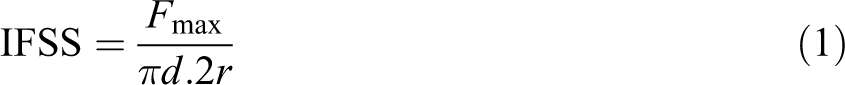
where IFSS is the interfacial shear strength, F is the load to de-bond the microdroplet, d is the fiber diameter, and 2r is the length of the fiber embedded in the matrix.
Heat distortion temperature
HDT was measured using a Q800 DMA (TA Instruments Co., New Castle, USA) according to ASTM D648, using method A. The penetration was 0.25 mm, the span 50 mm, the surface stress 1.82 MPa, and the heating rate 2°C min−1. Specimens were conditioned at 23°C ± 2°C and 50% ± 5% Relative Humidity (RH) for 40 h prior to the test.
Results and discussion
Crystallization and melting behaviors
Figure 1 shows the DSC cooling curves of virgin PA and PA/clay nanocomposites with clay loadings of 1, 2, and 3 wt%. For the nanocomposite systems, the crystallization temperature (Tc) of PA was about the same as that of the PA/clay. As reported, the organic intercalant located on the clay surface behaved like liquid at high temperature, 25 which could have weakened the nucleation efficiency of clay by causing the shielding effect, plasticizing effect, and/or miscibility that disturb the interaction between polymer and particle surface for some polymer/clay systems, such as PA/clay, 26 polyethylene, and terephthalate/clay. 27 Thus, the above effects should be considered with the derived nucleation efficiency.
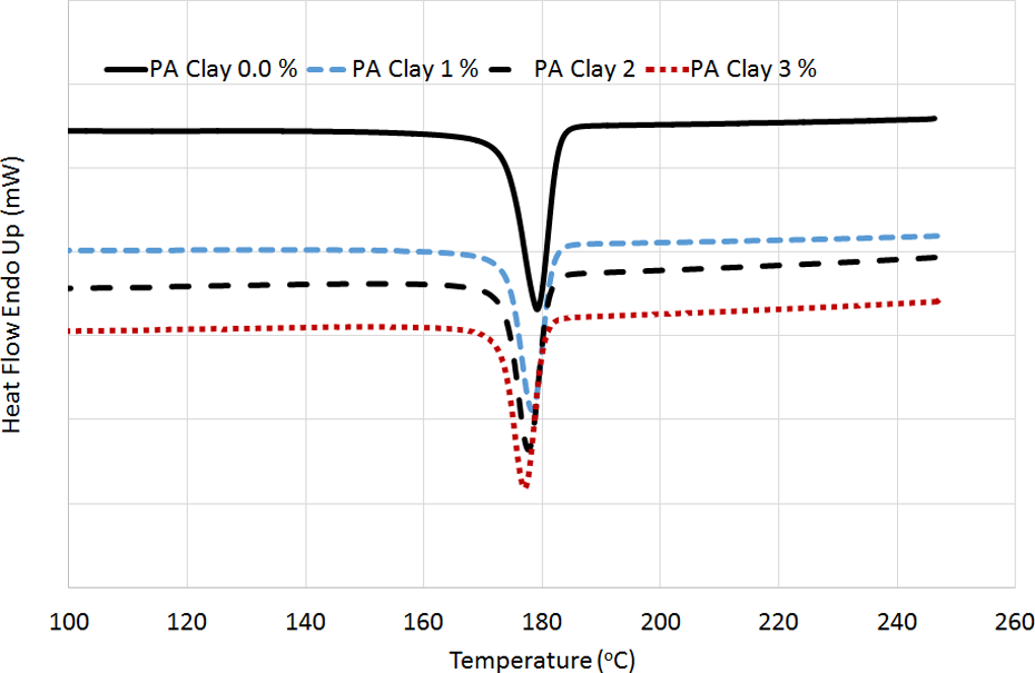
DSC thermographs of crystallization curves of PA6/clay nanocomposites. DSC: differential scanning calorimetry; PA: polyamide.
Figure 2 shows the DSC heating curves of PA and PA/clay (1, 2, and 3 wt%) nanocomposites. According to Figure 2, the melt process of polymer is revealed. The result suggests that the melt peak temperatures of PA and PA/clay nanocomposites are basically identical at 210°C. The shapes of the DSC heating curves of PA and the PA/clay nanocomposites are similar. It means that the addition of organo-clay does not affect the melt process of PA.
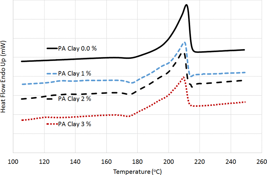
DSC thermographs of melting curves of PA6/clay nanocomposites. DSC: differential scanning calorimetry; PA: polyamide.
In addition, the crystallization enthalpy (ΔHc ) of PA nanocomposites is found to be decreased with the presence of clay. The degree of crystallinity (Xc ) for PA6 nanocomposites was also determined from DSC measurements. The Xc can be evaluated from the heat evolved during crystallization (ΔHc ) using the following relation:

Where ΔHm is the heat of fusion for 100% crystalline isotropic PA (ΔHm = 190 J g−1) and Φ is the weight fraction of the filler in the composite.
The results are shown in Figure 3. The degree of Xc of PA is decreased with addition of nanoclay. Generally, the inorganic fillers have two inconsistent influences on the crystallization of the semicrystalline polymers such as PA. As stated by Menga et al. 28 the fillers act as heterogeneous nucleating agents to facilitate the crystallization of polymers; on the other hand, they hinder the motion of polymer chain segments to retard the crystallization of polymers. As known, semicrystalline polymers have two-phase structure: crystalline and amorphous phases. Normally, the strength of the former is higher than that of the latter. Consequently, for a given polymer (neat PA6), it is evident that higher degree of Xc often implies stronger mechanical properties. Moreover, the mechanical properties of semicrystalline polymer matrix composites also depend on the dispersion of fillers and the interfacial adhesion between the fillers and the polymer matrix. On one hand, a stronger interfacial adhesion will hinder polymer crystallization during processing, which results in a lower degree of Xc of polymer matrix and consequently decreases the mechanical properties of polymer matrix. On the other hand, a stronger interfacial adhesion ensures the efficient load transfer from polymer matrix to the fillers, which leads consequently to high mechanical properties of composites. Therefore, some properties of the semicrystalline polymer matrix composites would be determined by the two competitive aspects. In a word, in this work the effect of interfacial adhesion on the mechanical properties of PA6/clay nanocomposites is more powerful than that of the degree of Xc as will be shown below.
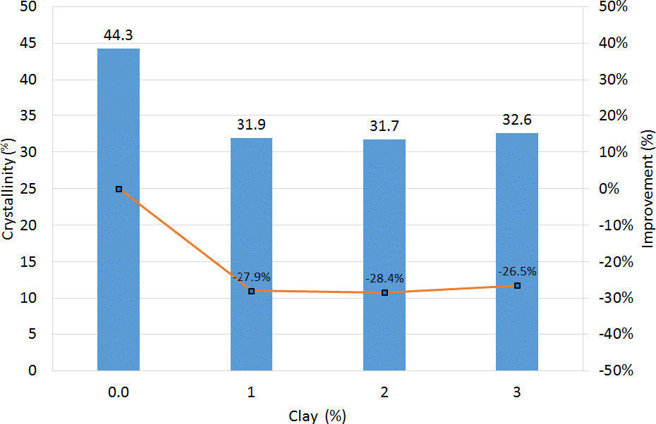
Crystallinity of PA6/clay nanocomposites. PA: polyamide.
Flexural properties
Typical stress–strain behavior from the flexural tests is shown in Figure 4. All specimens with different loadings of clay failed immediately after the flexural stress reached the maximum value; however, the stress–strain curves showed considerable nonlinearity before reaching the maximum stress.
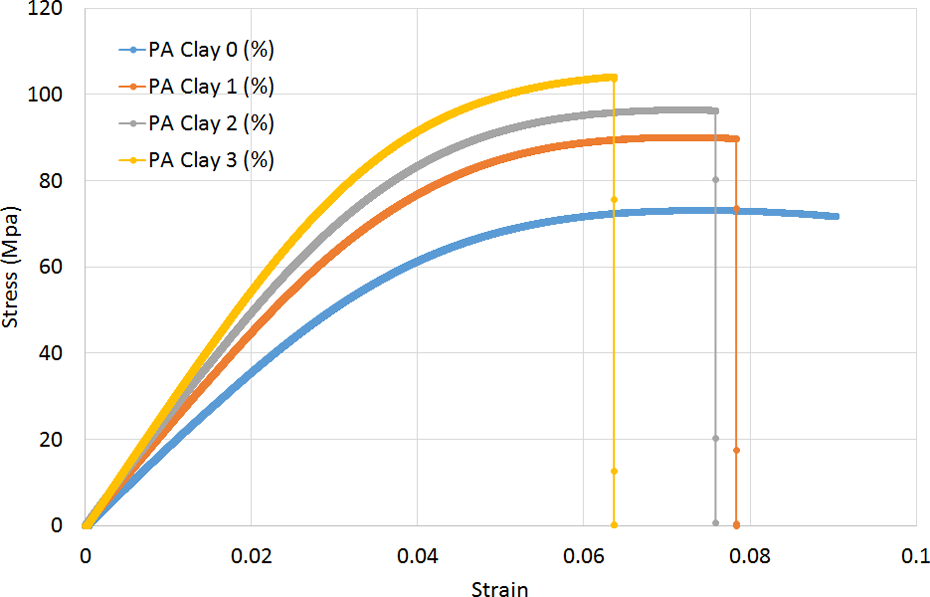
Stress–strain curve of bending test of PA6/clay nanocomposites. PA: polyamide.
Figure 5(a) and (b) shows the variation in modulus and strength with nanoclay content. It is observed that the strength and modulus of the nanocomposites increased continuously with increasing nanoclay contents. Optimal loading of clay was found at 3 wt%, improvements of about 8.7% in strength and 17.4% in modulus were observed in comparison to neat PA samples. The quality of the interface in composites usually plays a very important role in the materials’ capability to transfer stresses and elastic deformation from the polymer matrix to the fillers. 29 If filler matrix interaction is poor, the fillers are unable to carry any part of the external load. In that case, the strength of the composite cannot be higher than that of the neat polymer matrix, and if the bonding between fillers and matrix is instead strong enough, the yield strength of a filled composite can be higher than that of the matrix polymer. 30 In the same way, a high interfacial stiffness should correspond to a high composite modulus. Hence, the gradual increase in stiffness and flexural strength with increasing nanoclay reveals that stresses are efficiently transferred via the interface.
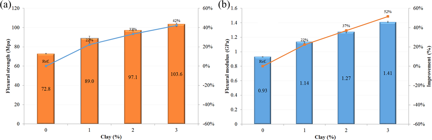
Flexural properties of PA6/clay nanocomposites (a) flexural strength and (b) flexural modulus. PA: polyamide.
Visual examinations on the fracture surfaces of filled PA by scanning electron microscope methods can often reflect detailed information on the cause and location of failure. Apparently, the fracture surface contains two distinct zones. From Figure 6, the first zone can be defined as initiation zone (zone 1) and the second is the crack propagation zone (zone 2) (Figure 6(a), (c), and (e)); the crack propagates from right to left. The fracture initiation zone 1 has a craze-like brittle appearance as shown in Figure 6. The breakdown of the craze initiation zone leads to the crack zone 2, which associated with crack propagation and can be further classified into two zones: (a) less brittle-like zone (2A) and (b) shear zone. Zone 2A is the extended region of fracture initiation, characteristic of lower crack growth and less brittle appearance (Figure 6(b), (d), and (f)).
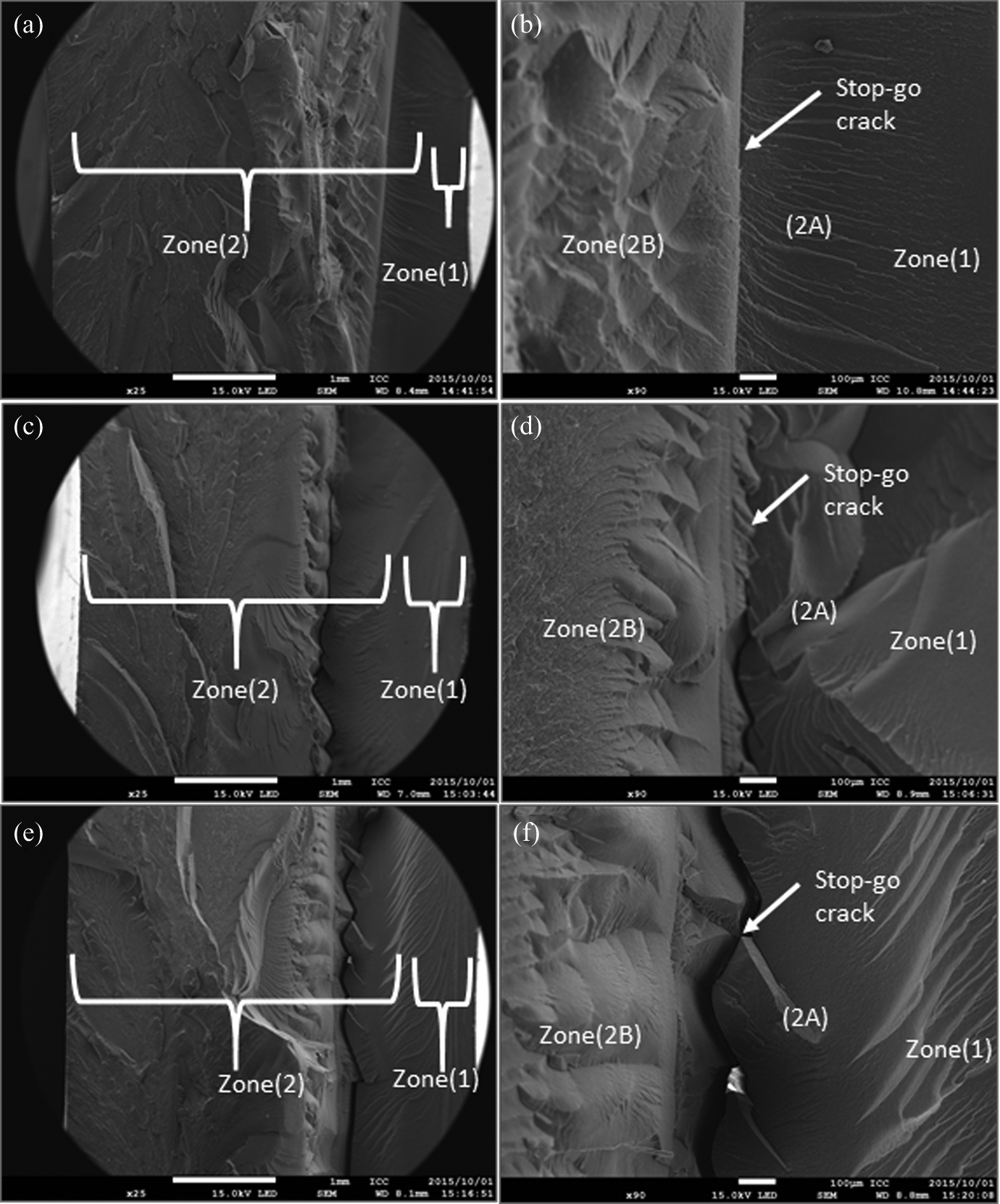
Scanning electron micrographs of the fracture surface of PA6 nanocomposites showing initiation (zone 1: craze-like zone) and different propagation zones (zone 2A: less brittle-like zone; zone 2B: hackle-like zone and stop-go boundary at different magnifications. PA: polyamide.
The crack initiates at a rate, which is of high magnitude such that the material does not have adequate time to respond, leading to brittle fracture zone (zone 1). Zone 2A is the extended region of fracture initiation, characteristic of slower crack growth. However, as crack propagation proceeds, the rate of crack propagation slows down with consequent decrease in brittle appearance and existence of river markings (zone 2A). Zone 2B shows the microstructure or roughness characterized by flow patterns along with small hackle-like features. This microrough structure could be ascribed to matrix shear yielding between the nanoclay layered silicates. Matrix shear deformation as an energy consuming mechanism in particulate filled resin has been reported by several authors. 31 Generally, a much rougher fracture surface is seen with increasing the concentration of clay into the PA matrix. The increased surface roughness implies that the path of the crack tip is distorted because of the nanoparticle, making crack propagation more difficult.
The boundary between zone 2A and zone 2B represents stop-go crack front, as evident in the high-magnification micrographs (Figure 6(b), (d), and (f)), which expected that the stop-go process is accompanied by stress relaxation. However, with addition of 3 wt% of clay, the high toughness of the nanocomposite results in slower breakdown of the initiation zone and is characterized by an initial propagation zone (2A), which has a macroscopically rougher surface (zone 2A in Figure 7(e) and (f)) than 1% clay (Figure 7(a) and (b)). The rate of crack propagation slows down with the existence of river markings, which became deeper at high clay concentrations, similar to those observed in nanocomposites reinforced with high contents of nanoclay particles 32 and CNTs. 33 It is suggested that the increasing number of river markings roughly corresponds to the number of isolated, well-dispersed nanoclay, which forced the cracks to propagate bypassing the clay and taking a long path. This resulted in dissipation of more energy through the well-known pinning and crack tip bifurcation mechanisms clearly shown in Figure 6(f.), by pinning the stop-go crack front. A schematic of the relative size of stop-go crack is summarized in Figure 7. The schematic shows the effect of high content of clay concentration (3%) on the pinning of the stop-go crack boundary.
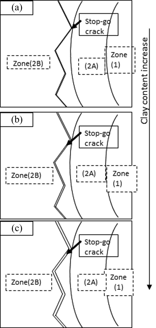
Schematic of the wider of stop-go crack zone with increasing clay contents in PA6. PA: polyamide.
Tensile properties
Tensile properties of nanocomposites and neat PA6 were evaluated for the reinforcing benefits of clay in polymer matrix (Figure 8). Figure 8(a) shows the variation in elastic modulus with clay content. It is observed that the modulus of the PA6 nanocomposites increases continuously with increase in the content of nanoclay. An improvement of about 13% is observed with an addition of 1 wt% of clay, whereas a maximum of 25% improvement is observed with an addition of 3 wt% of clay. The improvement in elastic modulus can be attributed to the exfoliation and good dispersion of nanoclay layers that restrict the mobility of polymer chains under loading as well as to the good interfacial adhesion between the layers and the matrix. Unlike the elastic modulus, nanocomposites of any clay content show a lower tensile strength than that of pure PA6. Akbari and Bagheri have attributed the reduction in the tensile strength to the formation of microvoids in the system due to the rapid increase in viscosity during mixing. 34 It is suggested that microvoids act as stress concentrators and facilitate shear yielding in the system and, therefore, reduce tensile strength. 34
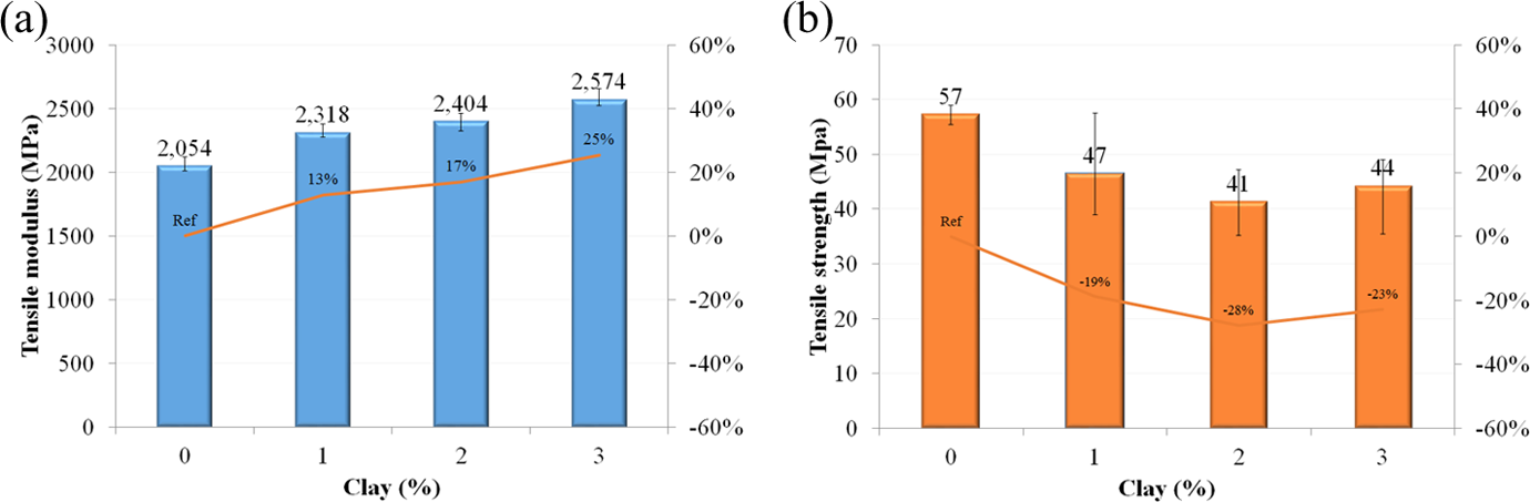
Tensile properties of PA6/clay nanocomposites (a) young’s modulus and (b) tensile strength. PA: polyamide.
Impact properties
In contrast, there was a sharp drop of nearly 34% in impact strength when 1 wt% clay was added into the PA6, followed by little variation with further increase in the clay content (Figure 9). Fornes and Paul 35 who studied the impact strength of several nylon–clay nanocomposites showed that the nylon with the greatest impact strength had the largest decrease due to addition of clay. The failure mechanisms in the impact specimens were somehow different from those of the bending fracture specimens. The SEM photographs (Figure 10(a) to (d)) indicate that the clay agglomerates, loosely bonded weak silicate layer bundles, became brittle under the high strain rate loading and acted as stress concentrators in the matrix, which can fracture easily due to the formation of microvoids even before the cracks reached the surrounding matrix material. Although some tails and river markings were visible for all nanocomposites, the pinning and crack tip bifurcations mechanisms were less evident under the impact condition than in quasi-static loading, indicating their contributions to composite toughness were much smaller. Some voids were present in the vicinity of clay agglomerates (Figure 10(f) and (g)), which are detrimental to impact fracture performance. 31 The rough fracture surface alone did not provide enough fracture resistance, while this situation is rather different from that of the particulate composites made from micrometer scale particles, such as Silicon dioxide (SiO2) or Aluminum oxide (Al2O3). For example, the charpy impact fracture toughness of SiO2-reinforced epoxy composites was shown to be much higher than that of a neat epoxy resin depending on the testing temperature. 36
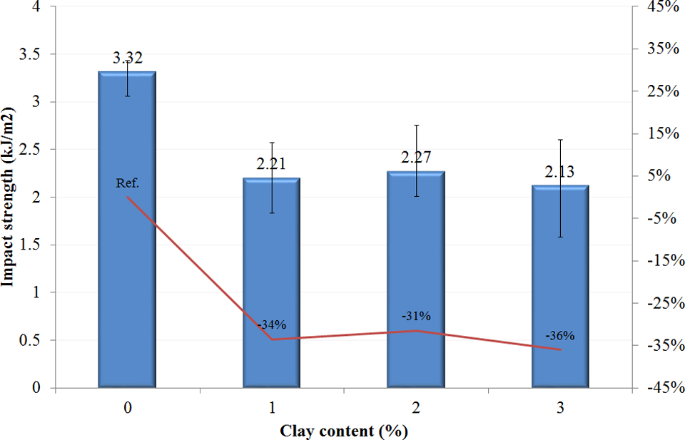
Impact strength of PA6/clay nanocomposites. PA: polyamide.
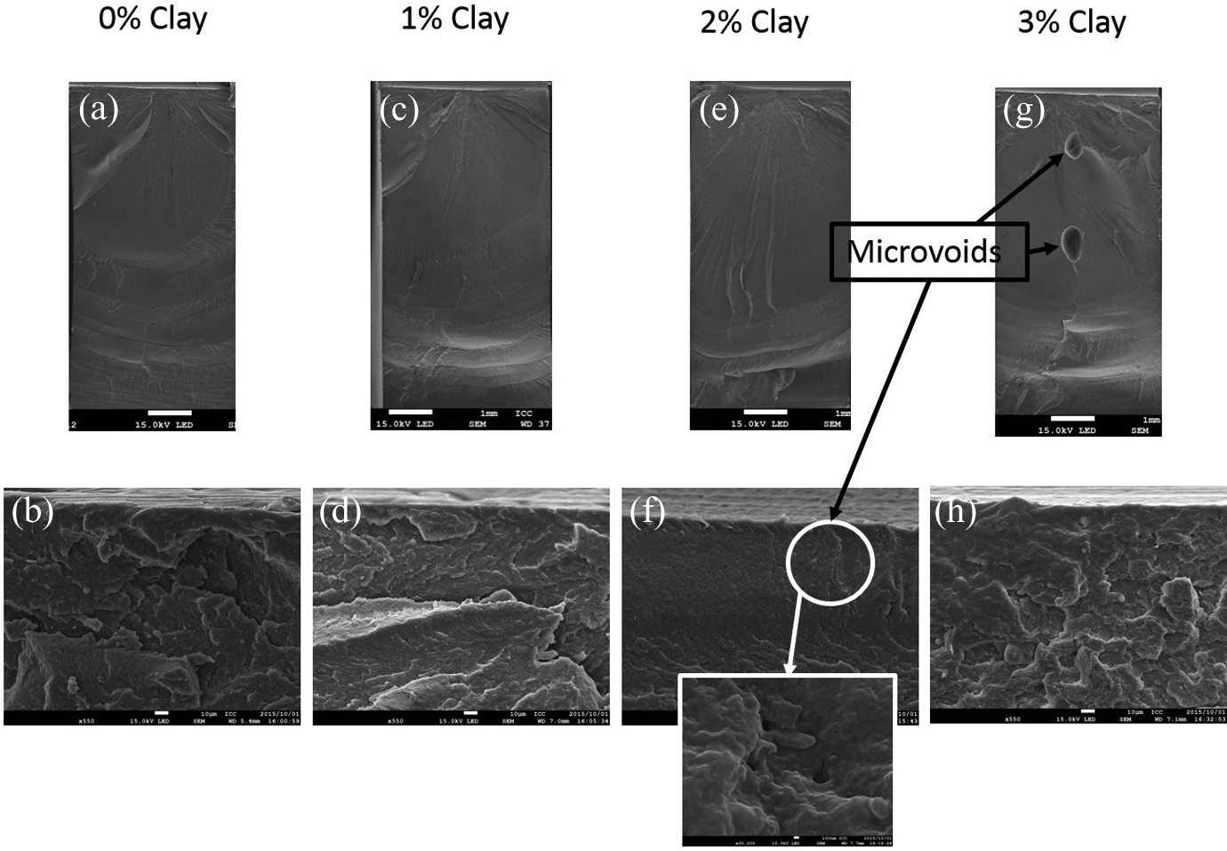
SEM of impact fracture specimens of PA6/clay nanocomposites (a, b) neatPA6, (c, d) 1% clay, (e, f) 2% clay, and (g, h) 3% clay. SEM: scanning electron microscopy; PA: polyamide.
Interfacial adhesion of CF-reinforced PA6/clay composites
The microbond test used in this study provides a simple and effective way to measure CF/PA6 IFSS values. The IFSS of the CFs with PA6 composites is shown in Figure 11. The embedded length of the microdroplets was approximately 90 µm for all samples.
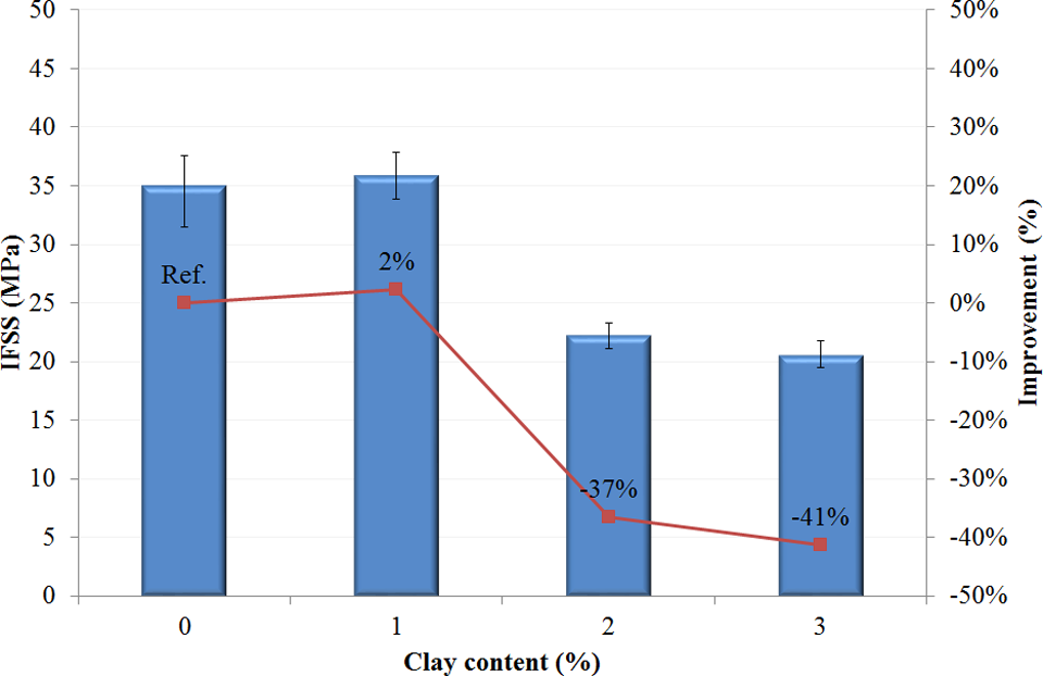
IFSS of PA6/clay nanocomposites. IFSS: interfacial shear strength; PA: polyamide.
The IFSS for microdroplets of 1 wt% clay composite to cause de-bonding was about the same as neat PA6 microdroplets. The IFSS values for 2 and 3 wt% of clay-filled PA6 were dramatically smaller than that of neat PA6. It seems that adding clay canceled the effect of octadecylamine. In general, octadecylamine has a very low molecular weight, which allows its highly mobilized short chains to interact actively with a great number of clay platelets in large clay surface areas during melt blending. This facilitates good clay dispersion and can achieve effective intercalation, meanwhile, the most of octadecylamine was incorporated at the interlayer of clay, thereby reducing the adhesion between CF and PA6. Arao et al. 37 reported that clay has negative effects on the interfacial properties of other material systems. They suggested that intercalation, which has a traction force into the interlayer of clay also possibly reduces the interfacial strength of fiber and matrix.
Figure 12 shows photographs of the microdroplet pull test specimens after the loading failure. These photographs further illustrated differences in the microdroplet failure patterns for neat PA6 and 3 wt% nanoclay. These pullout patterns are consistent with the IFSS results just discussed. For the neat PA6, a resin attached to the fiber was shown at the end of the separated part of microdroplet. The 3 wt% clay (Figure 12(b)) shows clean fiber surface with no resin attached to the fiber surface indicating adhesive fracture at the interface. An adhesive failure of the interface confirms the low IFSS measured by the microbond technique as well.
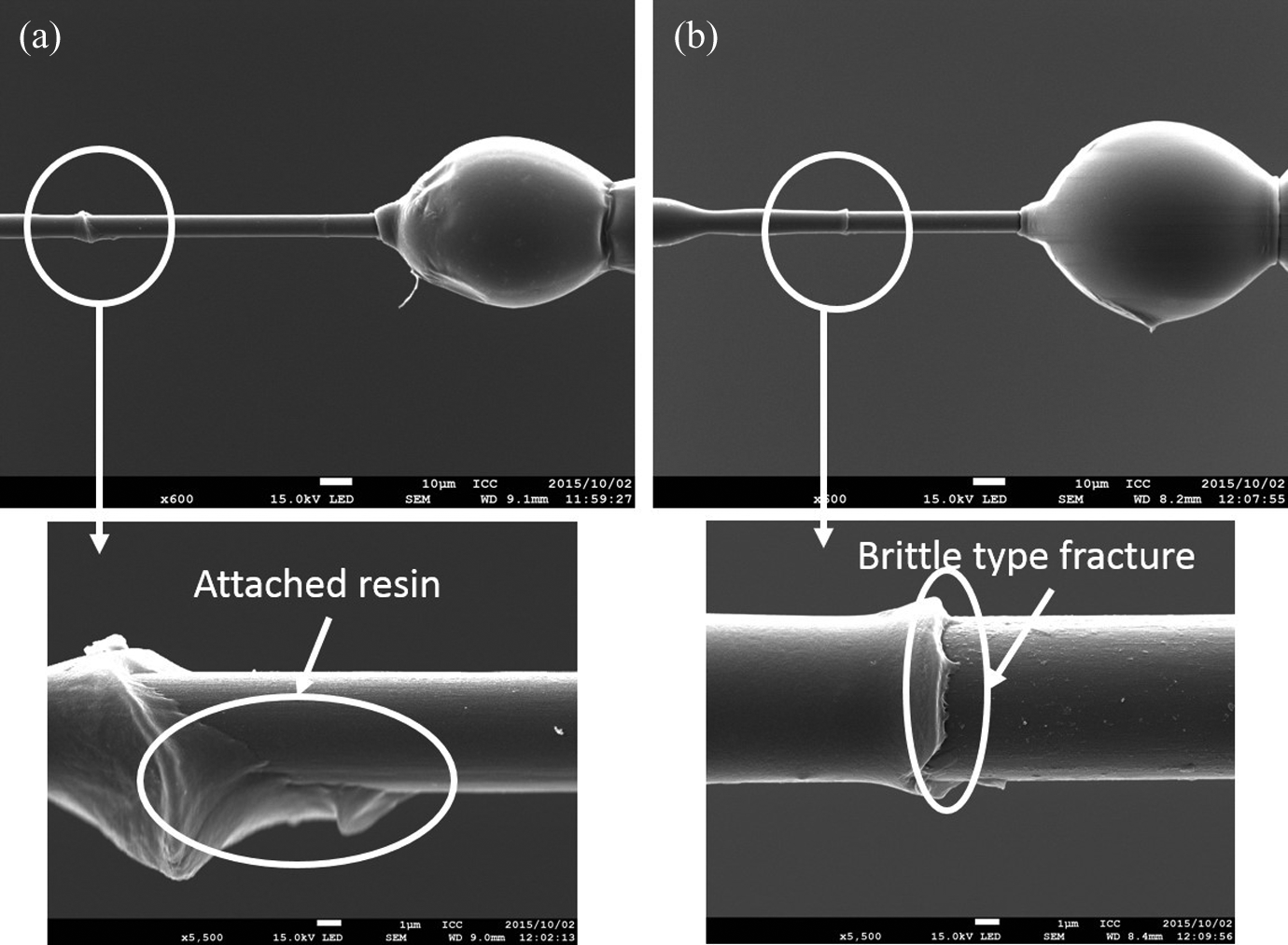
SEM photomicrographs of a microdroplet after debonding; (a) neat PA6, and (b) 3% clay. SEM: scanning electron microscopy; PA: polyamide.
HDT of nanocomposites
HDT is the temperature at which a polymer sample deforms under a specified load. Incorporation of nanoscale clay was shown to increase the HDT of PA6 drastically. 38 As mentioned above, the HDT of a polymer, as defined by ASTM D648, can be approximated from dynamic mechanical analysis results like those in Figure 13. In the ASTM method for HDT measurement, a bar specimen with a rectangular cross section is tested as a beam simply supported at both ends, with the load placed at its center providing a stress of 0.45 or 1.82 MPa. Temperature is increased at 2°C min−1, and the point at which the strain of the bar specimen reaches 0.2 is recorded as the HDT (ASTM D648). If one draws a horizontal line from strain axis at 0.2, the intersection with the strain curve will correspond to the HDT, read directly from the x-axis. Figure 14 shows the HDT values deduced in this way at 1.82 MPa as a one of stress levels specified by ASTM for nanocomposites. The HDT for the neat PA6 is about 50°C, which is similar to the value obtained by the ASTM HDT test.
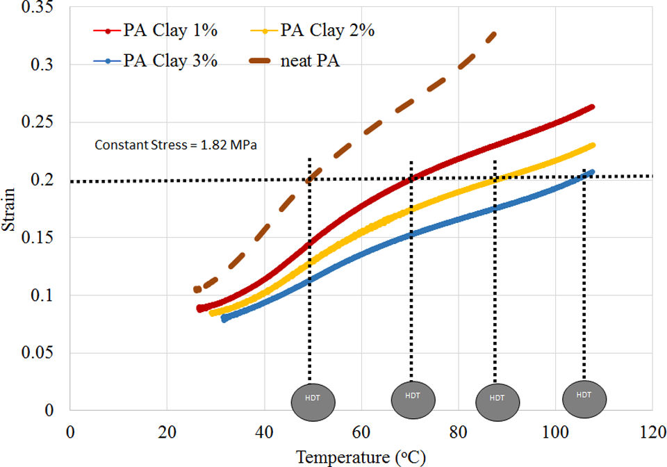
Dynamic mechanical data for PA6/clay nanocomposite at 1.82 MPa. The technique used for estimating the HDT is illustrated in the plot of strain versus temperature. PA: polyamide; HDT: heat distortion temperature.
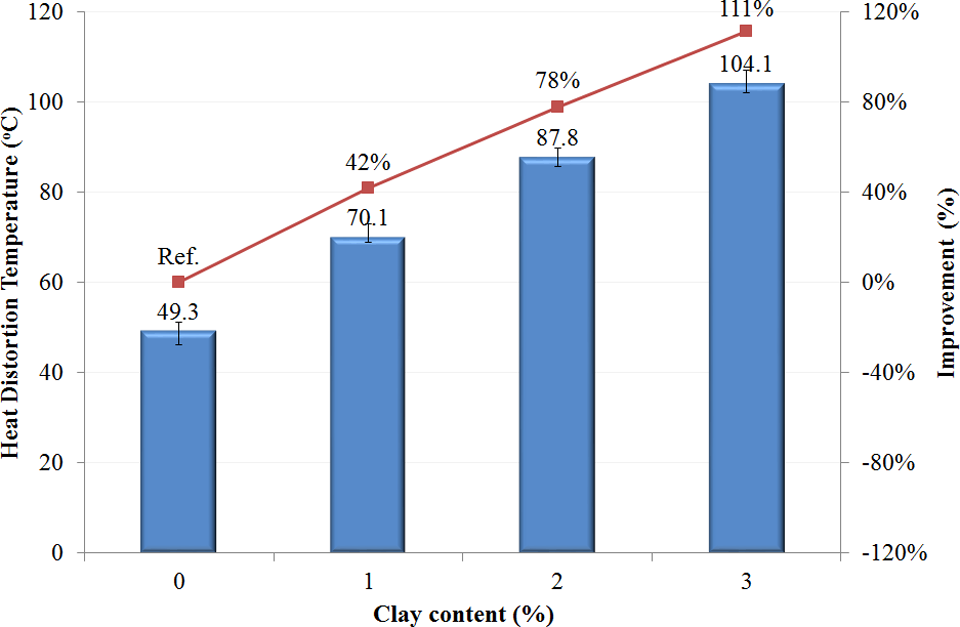
HDT of PA6/clay nanocomposites. PA: polyamide; HDT: heat distortion temperature.
The addition of 1 wt% clay increases the HDT to about 70°C. Also, the HDT was increased by about 111% from 50°C to 104°C, with addition of 3 wt% clay as shown in Figure 14. Since PA6 is a semicrystalline polymer, some level of stiffness can be maintained beyond T g and up to T m. 39 It has been repeatedly shown that clay typically increases the HDT of semicrystalline polymers much more effectively than amorphous polymers. 39
Conclusion
In the present work, the micromechanism of plastic deformation during bending and loading of PA-clay nanocomposites is examined and compared with the unreinforced PA under identical conditions of processing to underscore the determining role of clay as well as the effects of adding a nanoclay system on the interfacial, and mechanical properties of PA6 were investigated. Different weight percentages of Nanomer I-30E nanoclay (1, 2, 3 wt%) were dispersed in PA6 using a melt mixing method followed by injection molding. Major findings from this study are highlighted as follows:
De-sized Carbon fiber T700S (Innovative Composite Center, Ishikawa, Japan) is used to measure the effect of nanoclay on the IFSS. IFSS with addition of 1 wt% on nanoclay is the same as the neat PA6 but decreases dramatically with increase in the contents of nanoclay. The addition of clay into PA6 demonstrates their ability to simultaneously improve flexural strength and flexural modulus significantly by 42% and 52%, respectively. The gradual increase in stiffness and flexural strength reveals that stresses are efficiently transferred via the interface as observed for the nanocomposites up to 3 wt%. Tensile properties of PA6 containing nanoclay showed an improvement in young’s modulus, and the improvement of young’s modulus was at the expense of a reduction in the tensile strength.
The addition of clay up to 3 wt% brings about a considerable increase in HDT. The improved properties may be ascribed to the nano-fillers, which may activate energy dissipating mechanisms such as pinning and crack tip bifurcation mechanisms. Generally, a much rougher fracture surface is seen upon adding clay into the PA6 matrix. The increased surface roughness implies that the path of the crack tip is distorted because of the nano-layer silicates, making crack propagation more difficult.
Footnotes
Authors’ note
This work is a part of the Ishikawa Carbon Fiber Cluster project supported by Regional Innovation Strategy Support Program (The Ministry of Education, Culture, Sports, Science and Technology (MEXT)).
Acknowledgement
The authors are most grateful to Mr. Wataru Okumura and Mr Hisai Ueda for their help in Industrial Research Institute of Ishikawa (IRII) for their technical support in producing the masterbatch. Also, the authors are grateful to Mr Katsuhiko Nunotani, Mr Takehiro Shirai, Mr Kimihiko Uemura, and Mr Yoshihiro Saito in ICC for their valuable help and advice.
Declaration of Conflicting Interests
The author(s) declared no potential conflicts of interest with respect to the research, authorship, and/or publication of this article.
Funding
The author(s) received no financial support for the research, authorship, and/or publication of this article.