
Abstract
In this study, two types of polyurethane dispersion were applied as surface treatment for 10 types of washed/nonwashed carbon plain woven fabric-reinforced thermosetting and thermoplastic composites. To investigate the effects of surface treatment on the mechanical properties, the impregnation of various laminates was observed by a digital microscope. Dynamic mechanical analysis (DMA) was employed to investigate the interfacial interaction properties. Static tensile test was used to study the mechanical properties of composites. A correlation between the mechanical properties and interfacial interaction of composites was successfully observed. The acoustic emission (AE) from various composites was recorded in order to investigate the initial fracture and failure mechanism. Meanwhile, the knee-point method was also employed to look for initial fracture, which showed a good fit to initial strain detected from AE (amplitude > 80 dB). Furthermore, scanning electron microscopic images of single fiber and fractured carbon fiber bundles confirmed the interfacial properties evaluated by DMA analysis. Finally, remarkable improvement in mechanical properties (≈33.3%) of CF/PA6 laminates is discussed.
Introduction
Advanced composites reinforced with inorganic fibers, such as carbon, glass, and basalt, are expected for various applications including aerospace and aircraft structure, yachts, vehicles, as well as wind generator blades and other products on the account of their outstanding mechanical properties, lightweight, and longer service life. 1 –5 Since composites are in general composed of different constituents, there exist several factors which can influence the mechanical properties in comparison with monolithic materials. The mechanical properties of composites mainly depend on reinforcements/matrix properties, fiber surface morphology, and also on the impregnation and interfacial bonding nature between fiber and matrix. 6,7 On the one hand, the existence of lots of dry fiber bundles in composites without sufficient impregnation led to the lack of interfacial bonding and weak interfacial properties, which only supplied limited reinforcement and transfer of stress in composites. 8 That is, a low interfacial bond promotes large-scale debonding and reduces the load-carrying capability of the broken fibers. In contrast, a higher interfacial bonding tends to extend the crack transversely into the matrix at fiber breaks and results in increasing stress concentration around these breaks. The large-scale debonding and matrix cracking are major factors to reduce the strengths of both polymer–matrix 9–10 and metal–matrix composites. 11
The load transfer capability of the interface depends on the fiber/matrix adhesion which can be physico-chemical or frictional (or both) in nature. 12 Physico-chemical contribution, including chemical reactions, intermolecular interactions, surface-induced crystallizations, phase separation phenomena, and so on, seems to be more important in polymer composites than the frictional one. Since the interface is the key factor of composite performance, its engineering design (build-up) is being under spots of interest form both academia and industry. 13 Till now, great efforts have been made to look for suitable engineered fiber/matrix interface for improving the mechanical properties including strength, toughness, and so on, through lots of scientific and technological methods. Interface tailoring via sizing/coating on fibers, 14 –16 creation of hierarchical fibers by nanostructures, 17 –19 fiber surface modifications by polymer deposition, 15,20–23 and potential effects of matrix modifications on the interface formation 22,24 –26 are recent advanced methods.
Recently, polyurethane has attracted increasing attention as a kind of good surface coating material for man-made fiber owing to its advantages such as low viscosity, excellent bonding with the matrix material without special sizing of the fibers, relatively low price, and fast reaction time. Polyurethane is one of the most versatile polymers, which can exist in the form of both thermoplastic and thermosetting based on its initial reactants. Meanwhile, polyurethanes possess satisfactory properties including high tear strength, flexibility, elasticity, excellent abrasion resistance, and versatile shock absorption. 27 –29 As such, polyurethanes are often selected to extend product life cycle and conserve resource, which are substantial environmental considerations. 30 –32 However, most of the existing applications of polyurethanes focus on protecting the fibers during the manufacturing process but not considering popularly as a surface treatment for fiber-reinforced composites. Liao et al. 7 investigated the effect of different pickup ratios of polyurethane dispersion (PUD) sizing and their hybrid combination (silane–PUD) surface treatment agents on the mechanical performance of glass woven fabric-reinforced epoxy composites. Due to lack of other literatures about the polyurethane surface treatment, especially for carbon fiber–reinforced composites (CFRPs), it is meaningful to investigate the effect of PUD on the mechanical properties of carbon fiber-reinforced thermoplastic and thermosetting composites.
In the present study, two types of PUDs were applied as surface treatment for washed and original carbon plain woven fabric-reinforced thermosetting and thermoplastic composites. The effects of surface treatment on mechanical properties were investigated through dynamic mechanical analysis (DMA), tensile test, acoustic emission (AE) test, digital microscope, and scanning electron microscope (SEM) observation methods.
Materials and methods
Materials and specimens
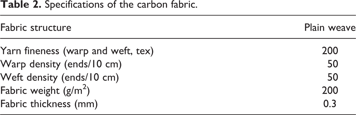
Carbon plain woven fabric (TC33-3K) from Formosa Plastic Corp. (Taipei, Taiwan) as reinforcement and polyamide 6 resin (MXD-PA) from Mitsubishi Gas Chemical Company (Niigata, Japan) and epoxy resin (MCP1110) from Maruhachi Corp. (Fukui, Japan) as matrix were used to manufacture thermoplastic CF/PA6 and thermosetting CF/Epoxy composites laminates, respectively. The mechanical properties of raw materials are shown in Table 1. Mechanical properties including tensile modulus, tensile strength, and density of PA6 and epoxy resin were similar. The specifications of the carbon plain weave fabric used in this investigation are listed in Table 2. The fabrics were processed into prepreg first using a hot compression technique. Before processing the prepreg, some carbon plain woven fabrics were washed two times with water (the ratio of original sizing reagent decreased from 0.98% to 0.43%). Then, two PUD agents including ETERNACOLL-UW-1005-E (marked as PUD(A)) and ETERNACOLL-UW-5002 (marked as PUD(B)) from UBE Industries, Ltd (Yamaguchi, Japan) were added to treat the CF plain woven fabric interface.
Mechanical properties of raw materials.
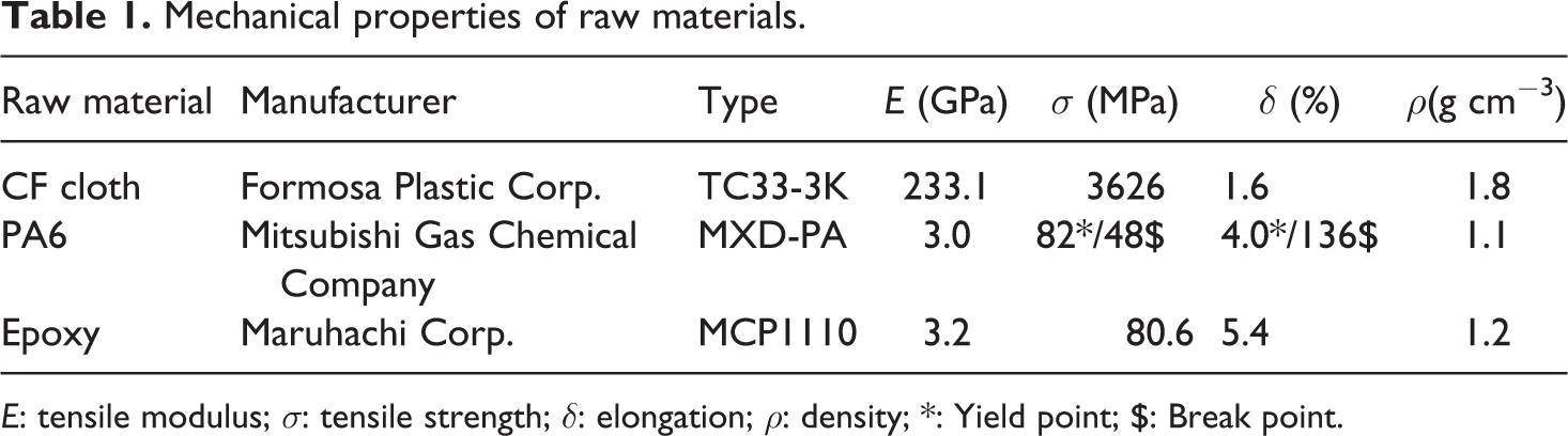
E: tensile modulus; σ: tensile strength; δ: elongation; ρ: density; *: Yield point; $: Break point.
Specifications of the carbon fabric.
The mass of the original carbon woven fabric (600 × 600 mm2 for CF/PA6 and 300×300 mm2 for CF/Epoxy) was measured as MO . Original PUD sizing solution was diluted with distilled water in a ratio of 1:10. Then CF woven fabrics were submerged into PUD treatment fluid in the tray for 30 s. Afterward, clean tissue was used to wipe out the redundant solution on treated CF woven fabric’s surface after taking out from the bath. Then treated CF woven fabrics were put into a convection oven for solvent evaporation (5 h at 60°C for PUD(A) and 1 h at 140°C for PUD(B)). At last, the mass of the treated carbon fabric MT was measured. The treatment particle’s pickup ratio (P(wt)%) of unit carbon fabric mass is calculated by the following equation:

where MT is the mass of treated carbon fabric after drying in an oven and MO is the mass of nontreated carbon fabric. Additionally, the pickup ratios of PUD(A) and PUD(B) on the CF woven fabric were 0.52% and 0.53%, respectively.
The thickness of a single carbon plain woven fabric ply lamina was 0.224 mm. CF/PA6 and CF/Epoxy laminates with a thickness of 2 mm were fabricated by laminating nine plies of prepreg sheets and cured at 280°C for 3.5 min under a compression pressure 4 kg/cm2 and at 130°C for 50 min under a compression pressure 25 kg/cm2, respectively. Five types of both CF/PA6 and CF/Epoxy laminates marked as “-Ori” (no washing, no PUD treatment), “-PUD(A)” (no washing, PUD(A) treatment), “-PUD(B)” (no washing, PUD(B) treatment), “-Wa-PUD(A)” (washing and then PUD(A) treatment), and “-Wa-PUD(B)” (washing and then PUD(A) treatment) were manufactured in the present investigation.
Experimental procedures
Dynamic mechanical analysis
DMA was carried out in a TA Instruments Co., Ltd. (USA), DMA 2980 using an oscillation frequency of 100 Hz over a temperature range from 30°C to 200°C at a heating rate of 3°C/min. Measurements were performed using a three-point bending device with a 50 mm span and rigidly held between the loading noses by a 100 mN static forces. Specimens were cut with dimensions of 60 mm ×10 mm ×2 mm. Storage modulus (E′) and loss factor (tan δ) were measured. By this technique, the glass transition temperature (Tg ) was defined as the temperature corresponding to the maximum value of the loss factor (tan δ). Three specimens of each kind laminate were repeated.
Quasi-static tensile test
Quasi-static tensile test was performed on a computer-controlled screw-driven Instron Universal Testing Machine (Japan) (55R4206) equipped with a 10-ton load cell at a strain rate of 2 mm/min under room temperature (23±0.5°C) based on ASTM D 3039. 33 Aluminum sheets were attached at the two grip sections of the specimens to increase the friction between specimen and collet. To obtain a significant result for each condition, three specimens (six specimens of CF/PA6-Wa-PUD(B) laminates) with dimensions of 250 mm ×25 mm ×2 mm were tested to evaluate the mechanical properties.
Acoustic emission
The detection of AE signals was carried out using a sensor (AE-901S, NF Electronic Instruments, Japan) from Physical Acoustics (Physical Acoustics Corporation, Princeton, USA) with a brand range between 20 kHz and 1 MHz. For continuous registration and saving of AE signals, the AE aystem with integrated Software AEWin 4.3 by Physical Acoustics was used. A threshold of 30 dB and a sampling rate of 5 MS/s were chosen.
Microscope observation
Objective specimens were filled with resin firstly. After the resin was completely cured, the specified surfaces/cross sections of specimens were polished, which are then observed to investigate the impregnation situations and crack propagation. Digital microscope (VHX-500F) from KEYENCE Corporation (Osaka, Japan) was employed in this study.
Scanning electron microscope
SEM, Jelo JSM 5200 (Japan), was used to inspect the topography of the specimens after mechanical failure. The samples were gold sputtered prior to the SEM observation.
Results and discussion
Impregnation checking of various treated composites
The cross-sectional observation of each kind of CFRP laminates for checking the impregnation situation is shown in Figure 1. Lots of dry carbon fiber bundles in CF/PA6 laminates could be observed as shown in Figure 1(a) to (e). In contrast, CF/epoxy laminates exhibited a more robust fiber/matrix interfacial bonding, better impregnation, and no obvious dry bundles could be observed as shown in Figure 1 (a′) to (e′). On the other hand, CF/PA6-Wa-PUD(B) exhibited fewer dry bundles than other peer CF/PA6 laminates after washing and PUD(B) treatment as shown in Figure 1(e).
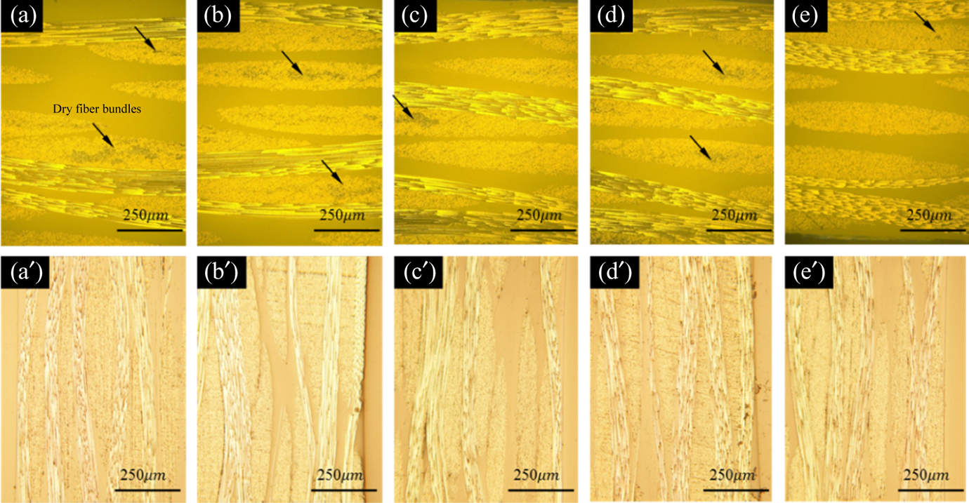
The cross-sectional observation of each kind of CFRP laminates for checking the impregnation situation: (a) CF/PA6-Ori, (b) CF/PA6-PUD(A), (c) CF/PA6-PUD(B), (d) CF/PA6-Wa-PUD(A), (e) CF/PA6-Wa-PUD(B), (a′) CF/epoxy-Ori, (b′) CF/epoxy-PUD(A), (c′) CF/epoxy-PUD(B), (d′) CF/epoxy-Wa-PUD(A), and (e′) CF/epoxy-Wa-PUD(B).
The formation of extensive dry fiber bundles in CF/PA6 laminates was resulted from the high viscosity of the polymer melt during the manufacturing process. The polymer melt only had limited flow under pressure, making it very difficult to achieve sufficient wet-out and impregnation around and within carbon fibers. The existence of lots of dry carbon fiber bundles led to the lack of interfacial bonding and weak interfacial properties, which only supplied limited reinforcement and transfer of stress in CF/PA6 laminates. In this case, the mechanical properties of CF/PA6 laminates were significantly below expectation due to the poor efficiency of fiber reinforcement. These composites also tend to fail via delamination at the early stages of load bearing due to the lack of reinforcement within the polymer-rich zones. 34,35
Dynamic mechanical thermal analysis of various treated laminates
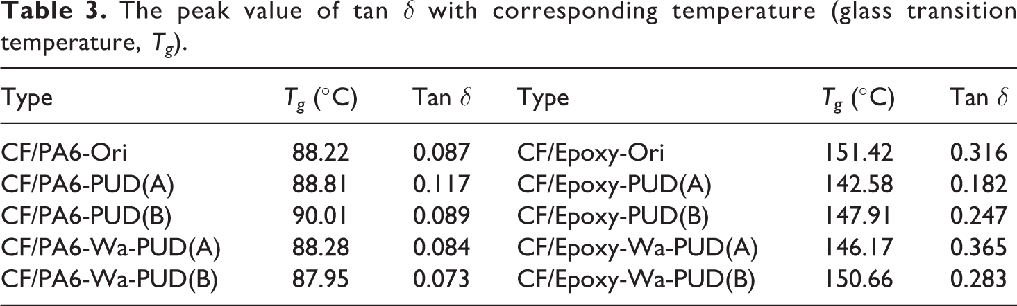
The damping (energy dissipation, tan δ) curves of the CF/PA6 and CF/Epoxy laminates with different treatments are given in Figure 2(a) and (b), respectively. The peak value of tan δ with corresponding temperatures (glass transition temperature, Tg ) are shown in Table 3. The results showed that peak value of tan δ of CF/Epoxy laminates decreased except CF/Epoxy-Wa-PUD(A) laminates. Meanwhile, the peak value of tan δ of CF/PA6-Wa-PUD(B) is lower than other CF/PA6-Ori laminates. It is known that a composite with a poor matrix/fiber load transfer tends to dissipate more energy than one with good interfacial interaction. 36,37 As such, CF/PA6-Wa-PUD(B) and CF/Epoxy-PUD(A) laminates possessed better interfacial interaction in their groups.
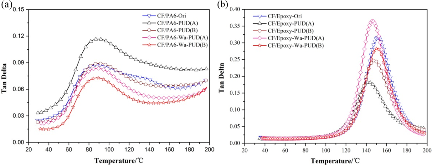
Temperature dependence of tan δ for CF/PA6 (a) and CF/epoxy (b) laminates.
The peak value of tan δ with corresponding temperature (glass transition temperature, Tg ).
Tension properties
Typical stress–strain curves of various CF/PA6 and CF/Epoxy laminates are shown in Figure 3(a) and (b), respectively. The mechanical properties including tensile modulus, strength, ultimate strain, and their coefficient of variation (CV) in detail are listed in Table 4. It is clear that, in general, CF/Epoxy laminates exhibited higher tensile modulus, strength, and ultimate strain than CF/PA6 laminates. On the other hand, CF/PA6-Wa-PUD(B) and CF/Epoxy-PUD(A) laminates after PUD treatment obviously showed better mechanical properties including tensile modulus, tensile strength, and ultimate strain than the original one and peers. Especially, the strength of CF/PA6-Wa-PUD(B) laminates increased about 33.3% than original plates after washing process and PUD(B) treatment. However, the strength of CF/epoxy-PUD(A) laminates only increased about 5% than original plates after PUD(A) treatment.
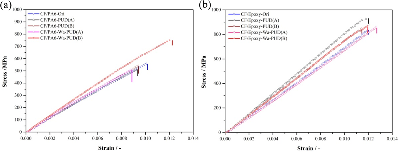
Typical stress–strain curves of CF/PA6 (a) and CF/epoxy (b) laminates under axial loading.
Mechanical properties of the CF/PA6 and CF/Epoxy laminates with various treatments.
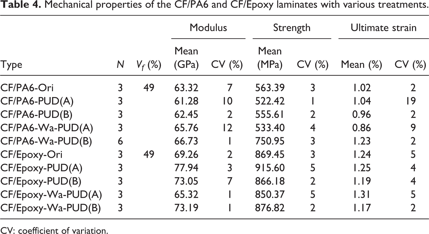
CV: coefficient of variation.
Relationship between DMA results and static tension property
The relationship between peak value of tan δ and tensile strength of CFRP laminates is given in Figure 4. Lower peak value of tan δ indicated stronger interfacial interaction properties. It is clear that the stronger the interfacial interaction properties, the higher the tensile strength. The relationship between tan δ and tensile strength of CF/epoxy laminates exhibited a linear relationship. Similarly, the relationship between tan δ and tensile strength of CF/PA6 laminates (except CF/PA6-Wa-PUD(B)) also exhibited a linear relationship. However, it is interesting that the tensile strength of CF/PA6-Wa-PUD(B) laminates greatly improved than other peers, which will be mainly investigated in the following parts.
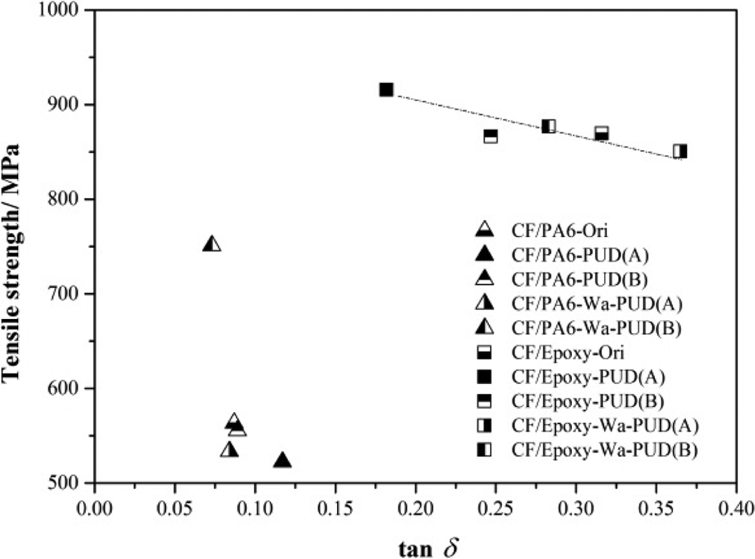
The relationship between tan δ(interfacial bonding capability) and tensile strength of CF/PA6 and CF/epoxy laminates.
Knee point
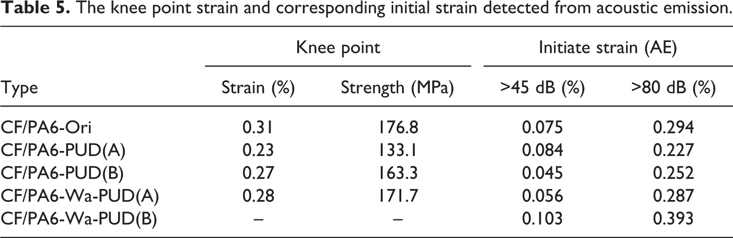
A characteristic property of textile composites is a knee point on the stress–strain curve of tensile test as shown in Figure 5. Knee point appeared at elastic limit, as such, knee point could be defined as a dropping point from the initial elastic line. It is possible that the initial fracture occurs at the knee point. 38 The strain and stress at the knee point of each CF/PA6 laminate is listed in Table 5. It is clear that CF/PA6 laminates, except CF/PA6-Wa-PUD(B) laminates, have obvious knee point near 0.2–0.4%. However, stress–strain curves of CF/PA6-Wa-PUD(B) laminates exhibited almost a linear relationship and no obvious knee point could be observed.
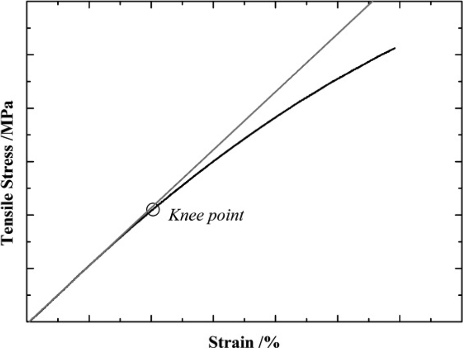
Knee point on the stress–strain curve.
The knee point strain and corresponding initial strain detected from acoustic emission.
Acoustic emission
To investigate the fracture process and fracture mechanism, AE analysis in combination with quasi-static tensile testing was used. Different levels of amplitudes (>30, >45, and >80 dB), which corresponded to different damages and fracture types of CF/PA6, are shown in Figure 6, which shows typical stress–strain curves of CF/PA6 laminates with accompanying AE, presented as cumulative event counts—N. About 103 AE counts (amplitude > 80 dB) were detected in total before the final fracture. But for CF/PA6-Wa-PUD(B) laminates, in total over 105 AE counts (amplitude > 80 dB) were detected before the final fracture. It is noteworthy that the fracture signal (>80 dB) of CF/PA6-Wa-PUD(B) exhibited a more obvious cumulative process. The corresponding initiate strains of two amplitudes (>45 and >80 dB) in detail are shown in Table 5 according to the initiate time. It is clear that the initial time of CF/PA6-Wa-PUD(B) is later than peers of CF/PA6 laminates, which means the initial interfacial debonding, matrix crack, and fiber fracture occurred lately. Composite laminates under increasing tension loading will bear higher stress if the initial interfacial and matrix crack and fiber break occur lately.
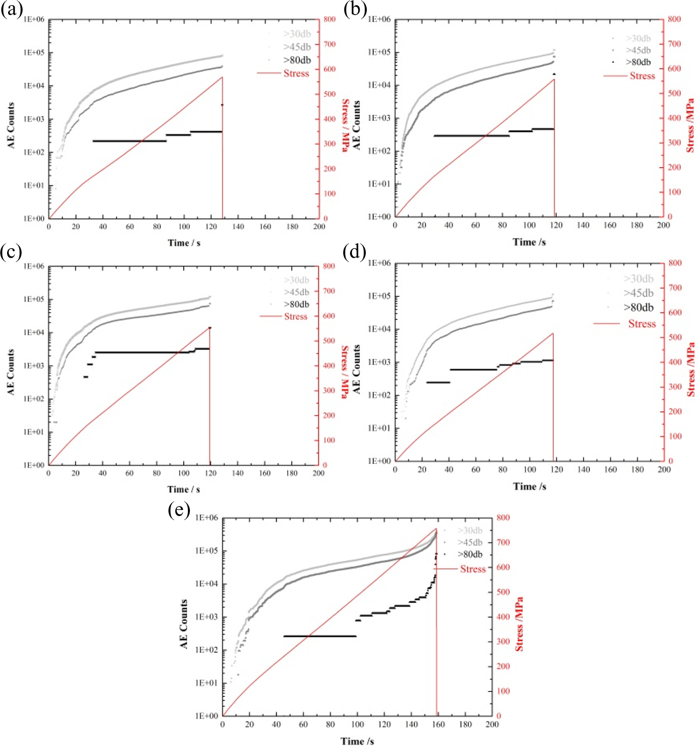
Acoustic emission analysis in combination with quasi-static tensile testing of CF/PA6 laminates: (a) CF/PA6-Ori, (b) CF/PA6-PUD(A), (c) CF/PA6-PUD(B), (d) CF/PA6-Wa-PUD(A), and (e) CF/PA6-Wa-PUD(B).
The relationship between knee-point strain and AE detected initial strain
The initial strain comparison between AE (>80 dB) and knee-point is shown in Figure 7. It is clear that the corresponding knee-point has a good fit with the strain from AE (>80 dB) except CF/PA6-Wa-PUD(B) laminates. As such, it could be inferred that the AE signal (>80 dB) is an effective evaluation criterion to detect the initial fracture in the present study and the initial fracture strain of CF/PA6-Wa-PUD(B) laminates should be about 0.393%.
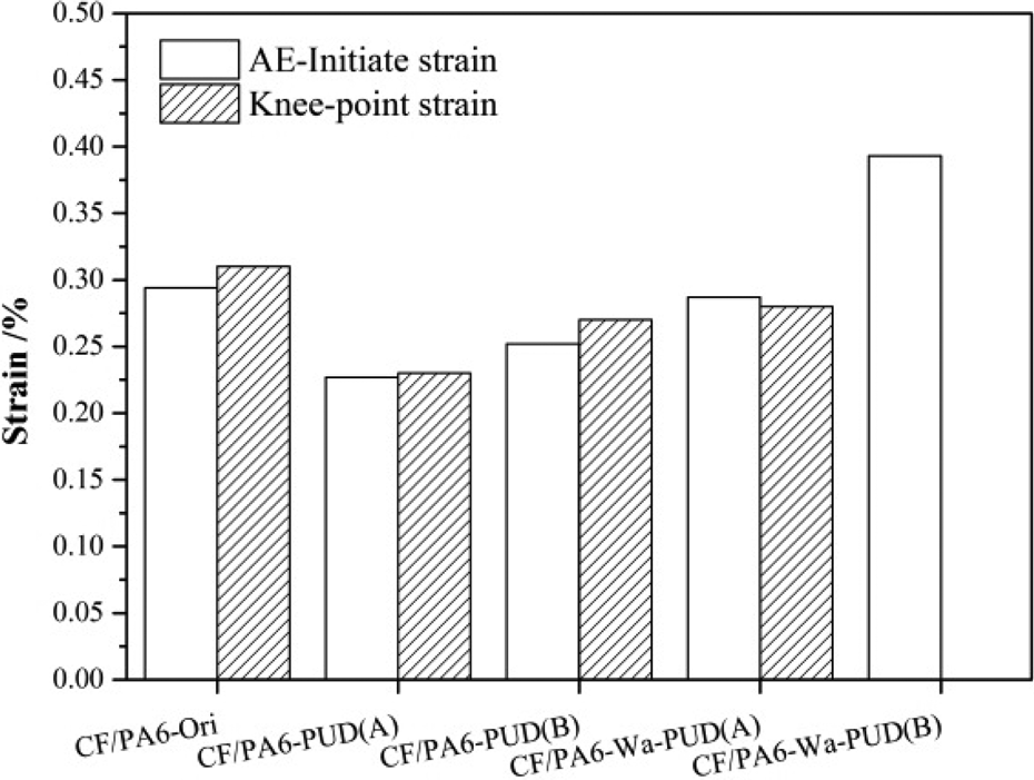
Initial strain from acoustic emission and knee-point strain.
The amplitude-percentage distributions detected from AE are shown in Figure 8. CF/PA6-Ori, CF/PA6-PUD(A), CF/PA6-PUD(B), and CF/PA6-Wa-PUD(A) laminate exhibited a similar Weibull distribution, and the peak percentage is concentrated in 50–55 dB. While for CF/PA6-Wa-PUD(B) laminates, the percentage of amplitude over 70 dB made a considerable proportion (≈40%), which means a large number of fiber breakages occurred under tensile loading.
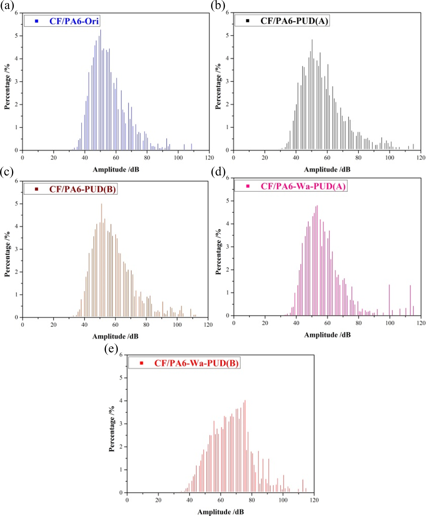
Amplitude distribution of CF/PA6 laminates with/without different treatments: (a) CF/PA6-Ori, (b) CF/PA6-PUD(A), (c) CF/PA6-PUD(B), (d) CF/PA6-Wa-PUD(A), and (e) CF/PA6-Wa-PUD(B).
Microscope observation through step-by-step tensile test
In order to clarify the fracture mechanism propagation difference between CF/PA6-Wa-PUD(B) laminates and other peers of CF/PA6 laminates, step-by-step tensile tests were performed under the same testing condition by using several specimens. In detail, the static tensile test was stopped at a designed strain level, and then the side cross sections of laminates were observed by a microscope at the strain including before initial strain, after initial strain, near ultimate strain, and ultimate strain. For CF/PA6-Ori laminates, the strain levels were chosen as 0.2%, 0.5%, 0.9%, and ultimate strain. While for CF/PA6-Wa-PUD(B) laminates, the strain levels were chosen as 0.2%, 0.6%, 1.1%, and ultimate strain.
The optical microscope observations of side cross section of CF/PA6-Ori and CF/PA6-Wa-PUD(B) laminates are shown in Figure 9(a)–(d) and Figure 9(a′)–(d′). Fiber/matrix debonding occurred firstly in dry carbon fiber bundles of CF/PA6-Ori laminates (as shown in Figure 9(a)), then crack propagated in the carbon fiber bundles (as shown in Figure 9(b) and (c)). But for CF/PA6-Wa-PUD(B) laminates with good impregnation, no obvious debonding or cracks could be found before knee point (as shown in Figure 9(a′)). The crack inside of weft bundles only could be observed after passing the knee-point (as shown in Figure 9(b′) and (c′)). The side cross sections of both CF/PA6-Ori and CF/PA6-Wa-PUD(B) laminates after final fracture are shown in Figure 9(d) and (d′), respectively. Different colors of arrows were marked to present interfacial debonding, matrix break, and crack between fiber bundles. It is clear that more debonding in fiber bundle and more matrix break occurred in CF/PA6-Ori laminates.
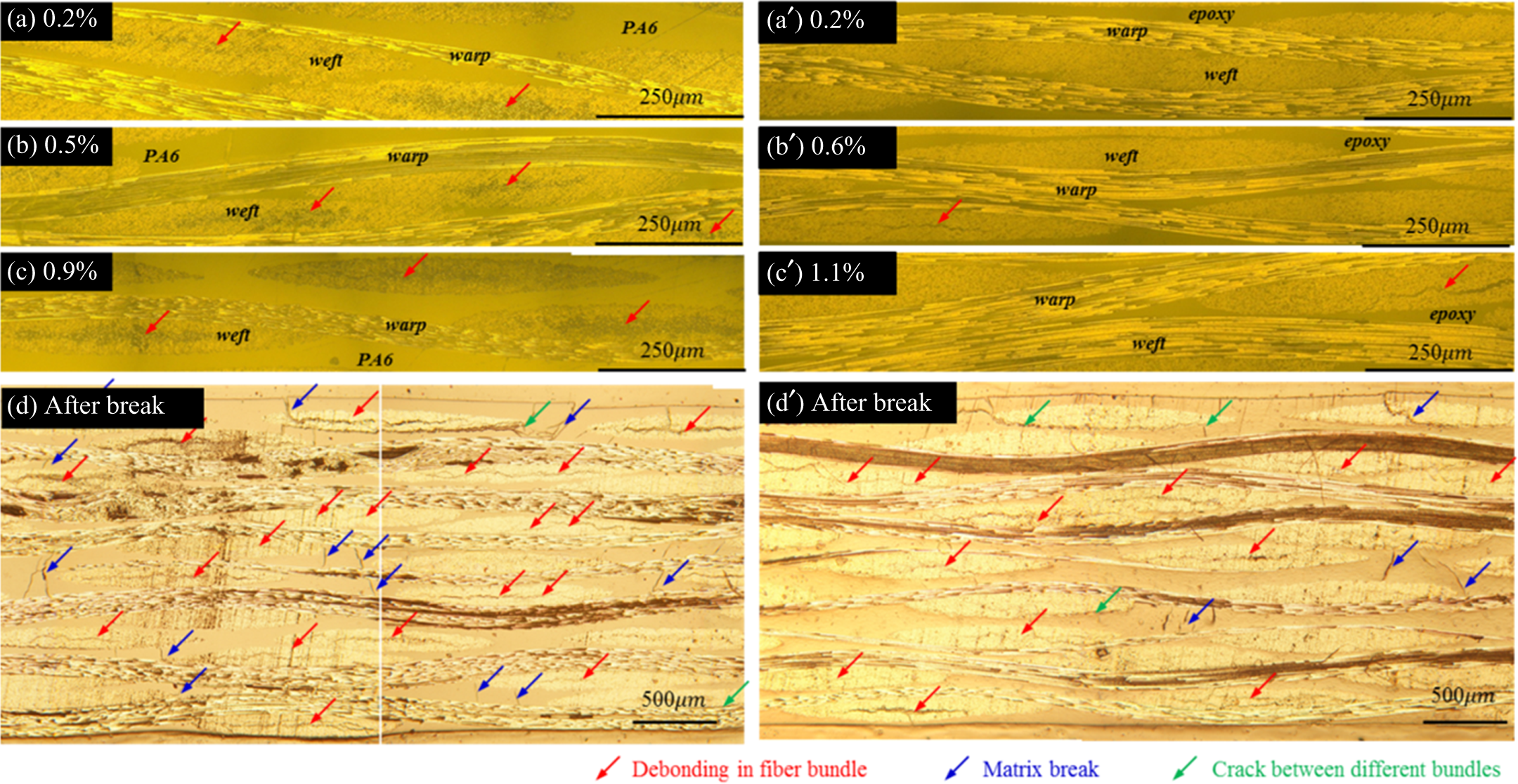
Cross section of CF/PA6-Ori (a-d) and CF/PA6-Wa-PUD(B) (a′–d′’) laminates in different strain stage after step-by-step tensile tests: (a)
SEM observation for single fiber and fractured composites
The fracture appearance of CF/PA6 laminates is shown in Figure 10. It is clear that the big difference between CF/PA6-Wa-PUD(B) and other peers. The fracture surface of CF/PA6-Wa-PUD(B) laminates with obvious boundary is straight vertical to the tensile direction as shown in Figure 10(e). But for peer CF/PA6 laminates, the crack propagated vertical to the tensile direction firstly then gradually turned along the loading direction as shown in Figure 10(a) to (d).
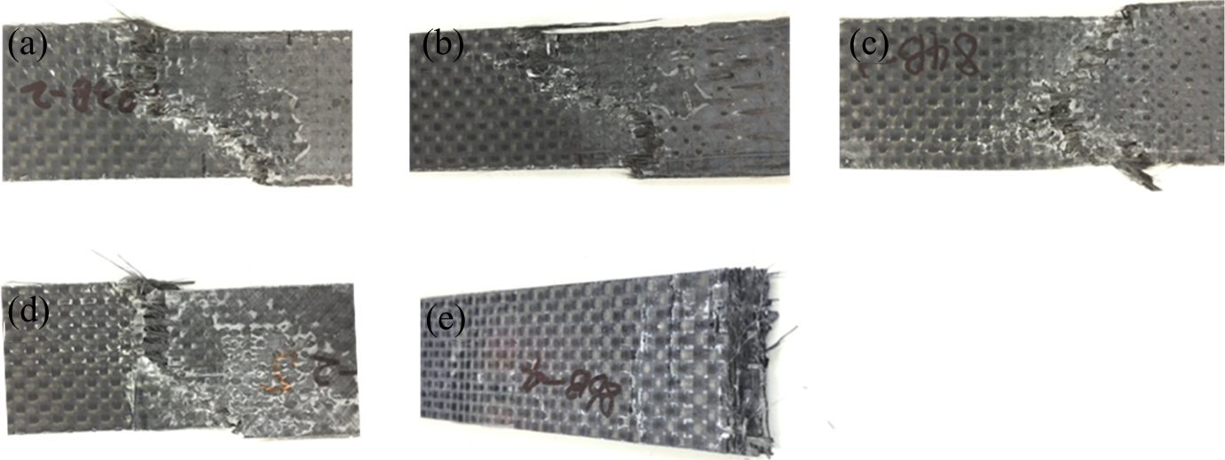
Fracture appearance of CF/PA6 laminates with/without different treatments: (a) CF/PA6-Ori, (b) CF/PA6-PUD(A), (c) CF/PA6-PUD(B), (d) CF/PA6-Wa-PUD(A), and (e) CF/PA6-Wa-PUD(B).
The SEM images of carbon fiber from CF/PA6-Ori, CF/PA6-PUD(A), CF/PA6-PUD(B), CF/PA6-Wa-PUD(A), and CF/PA6-Wa-PUD(B) laminates are shown in Figure 11 (a), (b), (c), and (e), respectively. Remarkable difference in the surface topography can be observed between the CF/PA6-Wa-PUD(B) and peer CF/PA6 laminates. As shown in Figure 11(a) to (d), carbon fiber of peer CF/PA6 laminates seems to be relatively neat and smooth, and a few narrow grooves parallelly distribute along the longitudinal direction of the carbon fiber. However, carbon fiber in CF/PA6-Wa-PUD(B) laminates surrounded with matrix is shown in Figure 11(e).
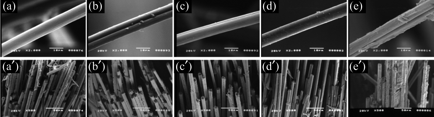
SEM observation of fiber surface (a–e) and fractured fiber bundles (a′–e′) of CF/PA6 laminates with/without different treatments: (a)/(a′) CF/PA6-Ori, (b)/(b′) CF/PA6-PUD(A), (c)/(c′) CF/PA6-PUD(B), (d)/(d′) CF/PA6-Wa-PUD(A), (e)/(e′) CF/PA6-Wa-PUD(B).
The micrographs of fractured bundles obtained from SEM in various laminates are shown in Figure 11(a′) to (d′). Extensive fiber bundle pullout could be observed for every type of CF/PA6 laminates. However, CF/PA6-Wa-PUD(B) laminates with carbon fiber bundles surrounded by matrix exhibited better interfacial bonding capability between carbon fiber and PA6 resin than peer CF/PA6 laminates. Rich matrix adhesion around bundles in CF/PA6-Wa-PUD(B) leads to debonding later along the interface and extended crack growth/delamination.
Mechanical properties improvement of CF/PA6-Wa-PUD(B) laminates
The mechanical properties of CF/PA6 laminates after washing and PUD(B) treatment improved about 33.3% than original CF/PA6 laminates. According to the above investigation, it could be found that the impregnation and interfacial properties of treated CF/PA6-Wa-PUD(B) improved a lot than original CF/PA6 laminates. Good impregnation and stronger bonding capability between carbon fiber and PA6 resin supplied sufficient reinforcement and transfer of stress in CF/PA6 laminates. As such, the initial fracture in CF/PA6-Wa-PUD(B) laminates postponed and more warp carbon fibers breakage occurred. It is noteworthy that the improvement of impregnation through the washing process and PUD(B) treatment is vital to improve the mechanical properties of CF/PA6 laminates.
Conclusion
In this study, two types of polyurethane dispersion (PUD(A): PUD-UW-1005-E and PUD(B): PUD-UW-5002, UBE Industries, Ltd.) were applied as surface treatment for washed and non-washed carbon plain woven fabric-reinforced thermosetting and thermoplastic composites. The effects of surface treatment on mechanical properties were investigated through DMA, tensile test, AE test, digital microscope, and SEM observation methods. From the analytical results, several findings were obtained as follows.
Strength of CF/epoxy-PUD(A) only increased about 5% than original laminates (CF/Epoxy-Ori) after PUD(A) treatment owing to the improved interfacial interaction.
Strength of CF/PA6-Wa-PUD(B) increased about 33.3% than original plates after washing process and PUD(B) treatment. Except the increased interfacial interaction, the improvement of impregnation of CF/PA6-Wa-PUD(B) laminates is the most vital factor in this study. Good impregnation and stronger interfacial interaction between carbon fiber and PA6 resin supplied sufficient reinforcement and transfer of stress in CF/PA6 laminates. As such, the initial fracture in CF/PA6-Wa-PUD(B) laminates postponed, and more warp carbon fibers breakage occurred.
Initial fracture detected by AE (>80 dB) has a good fit to knee-point strain in this study. As such, using AE (>80 dB) is an effective way to detect the initial fracture of those fabric composites without obvious knee point in their corresponding strain–stress curves.
Footnotes
Acknowledgements
The authors gratefully thank the supply of the PUDs from UBE Industries. Ltd..
Authors Contribution
Yuqiu Yang and Zhiyuan Zhang have contributed equally to this work.
Declaration of Conflicting Interests
The author(s) declared no potential conflicts of interest with respect to the research, authorship, and/or publication of this article.
Funding
The author(s) received no financial support for the research, authorship, and/or publication of this article.