
Abstract
The focus of this work was to study the effect of multiwalled carbon nanotubes (MWCNTs) on morphology, mechanical, and thermal properties of high-density polyethylene (HDPE) nanocomposites. MWCNTs/HDPE nanocomposites were prepared using submerged friction stir processing (SFSP) technique. The pristine MWCNTs without any pretreatment were blended with HDPE at a fixed traverse speed of 30 mm min−1 and various rotational speeds ranging from 1200 r min−1 to 2100 r min−1. The effect of rotational speed on MWCNTs dispersion in HDPE matrix was assessed using scanning electron microscopy. The experimental results showed the rotational speed affected the disperision of the MWCNTs. The mechanical properties of the composites were measured, and the results indicated that the tensile strength increased at first and then decreased with the increase of the rotation speed. The thermal properties of MWCNTs-filled HDPE nanocomposites were studied by differential scanning calorimetry, and the crystalline content of the prepared composites by the SFSP technology was increased. From the experimental research, it was found that the SFSP technique was a practical way to fabricate polymeric composites.
Keywords
Introduction
Polymer composites reinforced with nanofillers had a lot more appealing properties in industrial application due to their potential to improve performance of polymers even at low content. 1 –3 Carbon nanotubes (CNTs) were promising reinforced fillers because of their super high ductility, Young’s modulus, strength, unique electrical properties, 4 and similar chain structure to polymers. 5 However, CNTs were easily agglomerated in polymer matrix and were difficult to be separated because of van der Waals force. 6,7 So, the dispersion of CNTs in polymer matrix was vitally important for improving the performance of polymeric composites. The main methods of manufacturing CNTs-reinforced polymer nanocomposites were melt blending, 8 solution mixing 9 –11 and in situ polymerization. 12
Friction stir processing (FSP) has been developed by Mishra and coworkers as a generic tool for modifying and processing new materials 13 –15 based on the fundamental principles of the friction stir welding (FSW). 16 The principle of this technique is not complex, which consists of a rotating tool with a special shoulder and pin that slowly inserts into a monolithic workpiece until the shoulder contacts with the workpiece surface. During this process, the localized heat was from the friction heat, which generated at the tool/workpiece interface, as well as from the severe plastic deformation of the materials. The materials were broken, mixed, and undergone severe plastic deformation. 17 Ultimately, the microstructure of materials became densified, uniform, and refined.
Now, the FSP had been successfully applied to prepare superplastic aluminum (Al) alloys and magnesium alloys, to produce in situ composites, and to fabricate surface composites on Al substrate. 18 However, the reports about producing the polymer matrix composites by FSP were very few. Farshbaf Zinati et al. manufactured polyamide/multiwalled carbon nanotube (MWCNT) nanocomposites via FSP to investigate the thermomechanical behavior of composites and build a numerical model based on Lagrangian incremental formulation. The results showed that the MWCNTs were dispersed while passing the tool–pin because of high plastic strain applied on them. Also they found greater amount of the materials accumulated in the advancing side (AS) of stirred region after passing the tool–pin. Meanwhile, the MWCNTs were straightly and homogeneously dispersed throughout the polyamide 6, thereby caused the performance boost. 19 Azarsa and Mostafapour designed a novel tooling system that included a stationary shoulder, a rotating pin, and a heating system located inside the shoulder to produce high-density polyethylene (HDPE)/copper composites using FSP. The research showed ultimate tensile strength and modulus of elasticity, which increased by 10% and 30%, respectively, at transverse speed of 60 mm min−1 and shoulder temperatures of 110°C, which was higher than the values observed in melt mixing. 20 Barmouza et al. produced HDPE/clay nanocomposites using a novel method based on FSP in order to enhance the dispersion state of nanoclay particles and surface mechanical properties. The results showed that the microhardness of samples increased by 62% compared with the parent HDPE which was not processed by FSP. They concluded that FSP had a tremendous potential for surface modification of polymeric materials. 21
It is generally known that the polymer materials have a lower thermal conductivity, a shorter solidified time, and a lower melting temperature than metallic materials. In the process of polymer FSP, the low thermal conductivity or the polymer would lead the friction heat mainly concentrated in the processed compared to the metal materials creating a bigger temperature difference. So, it can result in the materials flow in this process was difficult to control. In order to solve these problems, different methods had been used, including in-process using a special tooling system 20 and submerged processing. 22 It usually made the experiment complicated by using a special tooling system. Submerged friction stir processing (SFSP) was a new variation of FSP, and the process takes place under a specific ambient temperature either in a bath or in water-circulation equipment. A schematic of the SFSP is shown in Figure 1. SFSP could not only decrease the peak temperature of stir zone but also effectively control the thermal cycle of the workpiece. 23 Some researchers have demonstrated that SFSP has great potential in the preparation of high-performance alloys and superplasticity alloys. 23,24 However, research studies on the fabrication of polymer matrix composites via SFSP are still limited.
According to the above ideas, the main aim of this study was to fabricate CNTs/polymer nanocomposites using SFSP and investigated the relationships of morphology, mechanical, and thermal properties of composites and FSP parameters. In the present work, HDPE and MWCNTs were utilized as matrix and fillers, respectively.
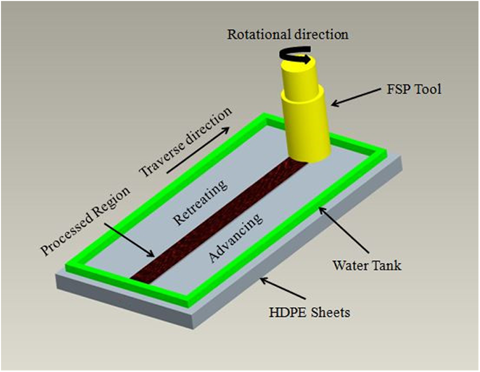
The schematic of SFSP.
Materials and methods
Commercial-grade HDPE, supplied by Shenzhen Anheda Plastic Products Co. (China), was used. The partial physical properties of this material are shown in Table 1. The size of samples used in this study is 200 × 50 × 6 mm3 (length, width, and depth, respectively). The CNTs used in this study are commercially available as JCMT-1-95 MWCNTs. The MWCNTs (average diameter: 11 nm, average length: 10μm, purity: 95%, and surface area >200 m2 g−1) is provided by Nanjing JCNANO Tech Co., Ltd (China). All raw materials are from the same habitat and batch.
The partial physical properties of the polyethylene sheet.
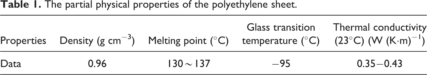
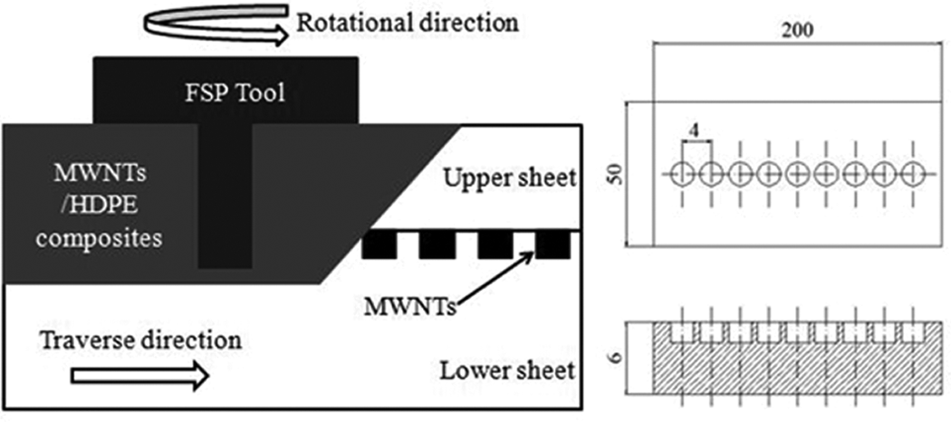
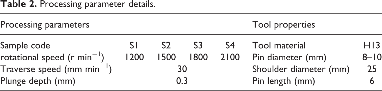
Before the FSP procedure, some special 2.5 × 1.0 mm2 (diameter and depth, respectively) blind holes were processed along the longitudinal direction of the HDPE plate for filling the CNTs. The traveling route of the rotating tool center was the same as this line. After drying process in the drying basin, the MWCNTs fillers were put and compressed in the blind holes. Then, another 4 mm HDPE sheet in same length and width with no holes was put upon the first sheet in order to prevent MWCNTs fillers overflow. Figure 2 shows the distribution of blind holes and configuration applied in this study. Finally, the rotational tool was inserted to the workpiece and moved along the path one had set to distribute the MWCNT fillers inside the processed region of the HDPE matrix. The rotational tool used in this experiment had a tapered pin. Figure 3 shows the FSP tool schematic. The tool and processing parameters are presented in Table 2.
Schematic illustration of the distribution of blind holes and configuration applied in this study (dimensions in millimeter).
Friction stir processing tool.
Processing parameter details.
A simple calculating method for estimating the volume fraction (ϕ) of MWCNTs was given in equation (1):
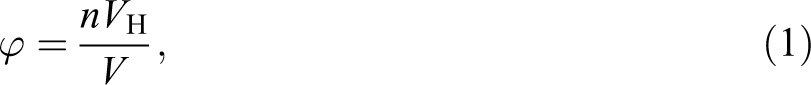
where n is the number of the blind holes, VH is the volume of each hole, and V is the total volume of processing region. The value of ϕ of MWCNTs in this research is about 2%.
The tensile test was carried out on the CMT 5105 SANS microcomputer-controlled electronic universal tensile testing machine in accordance with ASTM D638 standard. The samples were prepared following the type I method. Figure 4 shows the dimensions of the tensile specimen. The strength was obtained by averaging strengths of five individual specimens, which were processed under the same parameters.
For the macrostructure research, a new cross section was cut from the specimen using RM2235 model rotary-type microtome at a constant speed of 2 mm s−1. The microstructure of the specimens was studied using JSM-6360LV scanning electron microscopy (SEM). The SEM samples were fractured after freezing in the liquid nitrogen (N2). The fractured surfaces were coated with gold prior to observation.
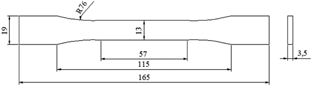
Configuration of tensile specimen (dimensions in millimeter).
The thermal behavior of the composites was analyzed by an STA 409 PC differential scanning calorimetry (DSC). The specimen (12–13 mg) was cut from the processing zones. The heating rate of all specimens was 10°C min−1 at 60°C to 170°C. The experiment was conducted with N2 as a protective atmosphere and the flow rate of N2 was 30 mL min−1.
Results and discussion
Macrostructure analyses
The upper surfaces and cross sections of the FSP samples in both the processing conditions are shown in Figures 5 and 6, respectively. The processing parameters were 1800 r min−1 and 30 mm min−1. Compared with the conventional FSP sample, the roughness of the submerged sample decreased. As can be seen from Figure 6, there were no apparent defects on the cross section of submerged sample. However, the conventional FSP sample was porous and uneven. The lower thermal conductivity of the polymer materials lead to a high temperature gradient during the manufacturing process. The heat mainly concentrated in the processing regions, and the materials flow in this process was difficult to control. The rotating shoulder threw away the soft material from the processed region, which resulted in great loss of MWCNTs. SFSP not only reduced the peak temperature but also effectively controlled the thermal cycle. 23,25 The surface of the sample appeared smooth because of the lower temperature and high cooling rate in the submerged condition, as seen in Figure 5(a). Furthermore, the flash of materials consistently presented along the processing edge on the retreating side (RS). The reason for this phenomenon is that the materials on RS did not enter the rotational zone adjacent the pin and the materials on the AS formed the fluidized bed adjacent the pin and rotates around it. 26
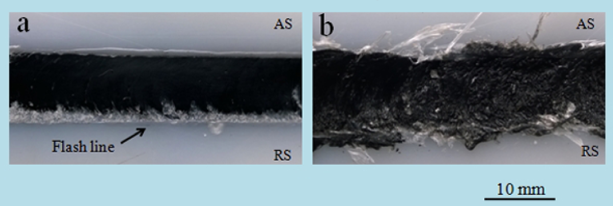
Surface images of the (a) submerged and (b) conventional FSP samples.
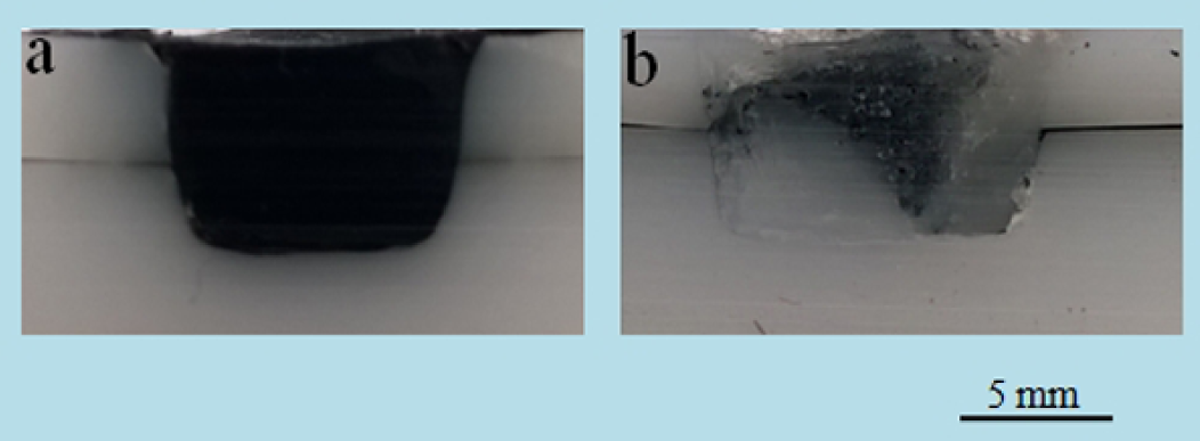
Cross-sectional image of samples in (a) submerged and (b) conventional conditions of FSP.
Figure 7 shows that the processing surface at different rotational speeds, and the traverse speed is 30 mm min−1. As observed in Figure 7, the processing surface displayed different morphology, the crown formation at the processing zone depended on the rotational speed applied. At low rotational speed (1200 mm min−1), the friction heating and materials flow were insufficient, which resulted in inadequate mixing of the materials, so the MWCNTs and HDPE alternately or simultaneously appeared on the surface. With the increasing of the rotational speed, the materials tended to be uniform. When the rotational speed increased to 1800 mm min−1, enough heating was applied to the materials. The flow and mixing ability of the materials improved, and the processing surface was smooth. However, further increasing the rotational speed to 2100 mm min−1, the surface morphology became rough due to too much friction heat concentrated in the processing area, causing the flow of the materials not control.
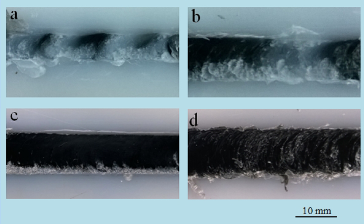
Surface appearance of samples fabricated in different FSP parameters: (a) S1; (b) S2; (c) S3; and (d) S4.
The cross sections of the SFSP samples at different rotational speeds are shown in Figure 8. The macrostructure of the samples that were prepared in both 1200 and 1500 r min−1 rotational speeds was heterogeneous and with cavities. With the rotational speed increasing from 1500 r min−1 to 1800 r min−1, the macrostructure was homogeneous. There were not apparent defects such as cavities and porosity. As the rotational speed increased up to 2100 r min−1, the processing zone was porous. It could enhance the materials flow by increasing the rotational speed. So, when the rotational speed increased from 1200 r min−1 to 1800 r min−1, the structure became almost uniform. However, the total heat was increased with the increasing of rotational speed. 13 The rotating speed of 2100 r min−1 was too high and too much heat concentrate in the processing zone due to the low thermal conductivity of polymeric materials, which resulted in the formation of pores. Simões and Rodrigues pointed that the polymer melting should have taken place during the FSW process. 27 Thus, these pores might be related to the decomposition of polymer materials in the heat.
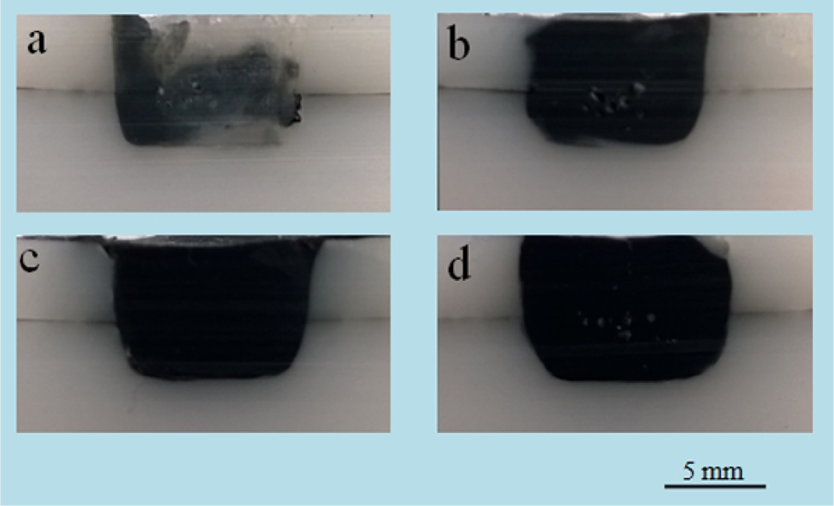
Macrostructure of samples fabricated in different FSP parameter: (a) S1; (b) S2; (c) S3; and (d) S4.
Microstructure analyses
Figure 9 depicts the structure of the MWCNTs and the composites. Figure 9(a) illustrates the morphology of the MWCNTs using SEM. It showed that the nanotubes were about 10 nm in diameter and several microns in length. Figure 9(b) and (c) shows the SEM images of the specimens produced by the SFSP at the tool rotational speed of 1200 and 1800 r min−1. The tool rotational speed was contributed to the variety of the microstructure. During the FSP, shear force that worked on the polymer materials helped to disperse the MWCNTs in the HDPE matrix. The higher the rotational speeds, the higher the shear force. So, structures of the samples prepared in higher rotational speed were more uniform than those prepared in lower rotational speed. The high-magnification morphology of MWCNTs was observed, as illustrated in Figure 8(d). The MWCNTs (see arrow) were distributed in the HDPE matrix basing on the monodisperse state. This illustrated that it could effectively prevent the clustering of the MWCNTs by the SFSP technology. It was no doubt that improving the dispersion of MWCNTs was essential to improve the performances of the composites.
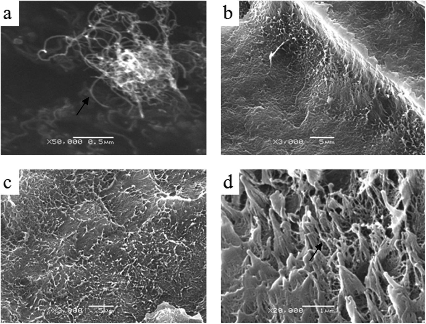
SEM images show the morphologies of MWCNTs and composites: (a) the raw MWCNTs, (b) S1 sample, (c) S3 sample, (d) the high-magnification morphology of S3 sample.
Mechanical properties
The values of tensile strength for fabricating HDPE/MWCNTs nanocomposites are presented in terms of tool rotational speed in Figure 10. It also should be mentioned that the tensile strength of the HDPE, which was not processed by FSP, was measured to be 22.5 MPa (hereafter called S0). According to the results, a 20% increase was observed in the case of tensile strength values of the composites fabricated by SFSP method, whereas the sample that was prepared by the melt processing method showed a 12% increase in tensile strength. 28 The high values of tensile strength obtained via SFSP could attribute to the good dispersion and the energy absorbing effect of the MWCNTs in the HDPE matrix. 7
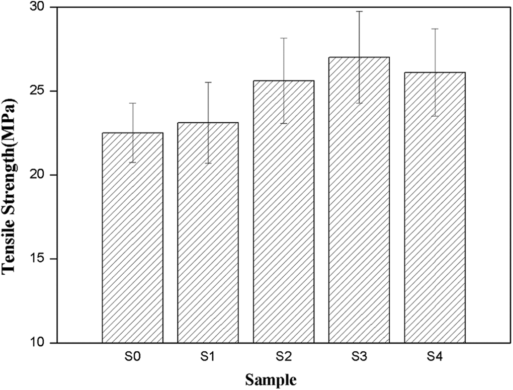
The variation of tensile strength of different samples.
On the role of rotational speed in the dispersion state of MWCNTs and tensile strength of nanocomposites, it had to be mentioned that two factors could be responsible for this behavior. On one hand, during the FSP, the shear forces applied on the matrix caused the fillers to separate leading to increasing the mixing and flow of reinforcement and matrix. 20,21 Therefore, higher rotational speeds induced higher shear forces on polymer nanocomposites resulting in higher dispersion of the MWCNTs in the HDPE matrix, which finally increased the tensile strength values. 23 On the other hand, increasing the rotational speed resulted in the much heating to be concentrated in the processing regions, which induced many pores that acted as stress concentration points in the composites, leading to the decrease in tensile strength values of the composites. It could explain why the 1800 r min−1 rotational speed was the best value for fabricating HDPE/MWCNTs nanocomposites by this variant of FSP.
Furthermore, the sample without MWCNT was prepared via SFSP under the same process parameters as the sample 3. The tensile properties of the sample were 19.7 MPa, which was lower than raw HDPE. Strand et al. studied the microstructure properties of polypropylene friction stir-welded sheets, and they pointed that the polymer microstructure was more or less disrupted. 29 Thus, the decrease of the tensile properties was related to the variation of the polymer microstructure.
Thermal properties
The crystallization properties of the HDPE composites were evaluated using DSC. By comparison, the HDPE samples that were subjected to the same station treatment without the MWCNTs were also scanned to investigate. Figure 11 shows heat flow measurements of representative samples used in this study during heating from 60°Cto 170°C. The melting behavior of HDPE composites was indicated in the thermograms as endothermic peaks. The crystallinity of materials was quantified using the following equation 30 :
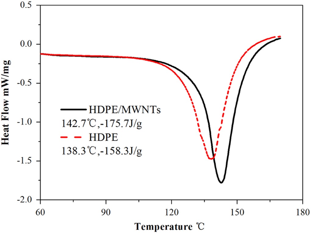
DSC thermograms of HDPE and composites (S3).
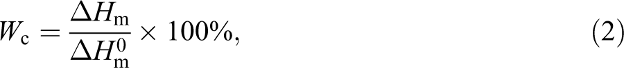
where ΔHm is the melting enthalpy of the sample and
Conclusion
In this investigation, HDPE/MWCNT nanocomposites were successfully fabricated by SFSP. The maximal tensile strength value of 27 Mpa, which was higher than HDPE matrix (22.5 MPa) was observed for the sample produced at rotational speed of 1800 r min−1. The SEM observation indicated the fine dispersion of the MWCNTs in the HDPE matrix by SFSP. The crystalline content of the composites was increased duo to the well dispersion of the MWCNTs.
Footnotes
Declaration of Conflicting Interests
The author(s) declared no potential conflicts of interest with respect to the research, authorship, and/or publication of this article.
Funding
The author(s) disclosed receipt of the following financial support for the research, authorship, and/or publication of this article: The authors are deeply grateful for the support of National Natural Science Foundation of China (grant no: 51475232). This is a project funded by the Priority Academic Program Development of Jiangsu Higher Education.