
Abstract
Fibre-reinforced thermoplastic composite materials can be manufactured rapidly using a thermoforming process. The assortment of thermoplastic matrix systems is manifold and starts from bulk plastic like polypropylene (PP) up to high-performance systems like polyether ether ketone. High-performance thermoplastic polymers have durable properties but relatively high raw material costs. For structural application, engineering methods are needed to ensure the availability for use over the full range of the life cycle of parts. This equates to at least 15 years under exposure to varying climatic conditions for an automobile component. Bulk plastics have complex viscoelastic behaviour, which means that advanced methods are needed to ensure the long-term behaviour of both the pure plastic or fibre-reinforced materials with such a matrix system. In the following study, the creep behaviour of a glass fibre-reinforced PP material is investigated using different uniaxially loaded creep tests at different load and temperature levels. Starting from this empirical base, two characteristic creep functions are derived using a modified Burgers approach. To transfer the results of uniaxial creep situations to a three-dimensional multiaxial stress state, a method to interpolate the experimental creep curves is presented. This developed creep model is integrated into the implicit non-linear finite element program SAMCEF/Mecano and used to predict the creep behaviour of a complex laminate. The results are then validated against the performed experiments.
Keywords
Introduction
The application of composite materials in primary structures of aerospace components like fuselage or wings is nowadays state of the art. The advantages of these materials are the specific lightweight properties. A large challenge, however, is presented by relatively large manufacturing times, which lead to high component prices. To accelerate the cycle time, the commonly thermoset matrix of the compound can be replaced by a thermoplastic matrix. These thermoplastic composite materials can be manufactured rapidly using a thermoforming process which can also be combined with other processes, such as injection moulding. The assortment of different thermoplastic matrix system is manifold and starts from bulk plastic like polypropylene (PP) up to high-performance systems like polyether ether ketone. High-performance thermoplastic polymers are durable and can be subjected to high temperatures. The disadvantage of these polymers is the relatively high raw material cost. Therefore, the application range is limited to high-performance applications. In contrast, bulk plastics have a relative low price combined with a lower performance. Especially, the automotive industry is searching for a lightweight material selection that offers a suitable compromise between material performance and production costs. Tougher emission standards within the European Union have increased the automotive industries interest in using lightweight bulk plastics for exterior application in addition to its existing use in the interior. Such an application requires the engineering design methods to ensure the availability for use over the full range of the life cycle of the part. For an automobile component, this amounts to at least 15 years subjected to varying climatic conditions. This long utilization time in combination with the materials complex viscoelastic properties emphasize the need for advanced methods to describe the long-term behaviour of both pure and fibre-reinforced plastics. In the following study, the creep behaviour of a glass fibre-reinforced PP material is investigated using different uniaxial loaded creep tests at different load and temperature levels. Starting from this empirical base, creep functions are derived. To transfer the results of uniaxial creep situations to a multiaxial stress state, a method partially based on Puck’s criteria is introduced. The developed creep model is integrated into the implicit non-linear finite element (FE) program SAMCEF/Mecano and experimentally validated.
Theoretical aspects
The assumption of an ideal linear elastic behaviour of a solid is unfeasible for the description of plastic materials, whose viscoelastic time-dependent behaviour cannot be neglected. Viscoelastic behaviour is defined by an elastic part and a viscous part. The deformation energy is divided into an elastic, stored part, which is reversible, and an irreversible part, which dissipates as heat. Viscoelastic effects include both the strain rate-dependent energy dissipation and long-term effects such as relaxation and creep. Relaxation is defined as decrease of stress over time at constant deformations. Creep means increasing deformation whilst the loads remain constant. The theories of viscoelasticity can be divided into theories of linear and non-linear viscoelasticity. For linear viscoelasticity, the behaviour is independent of the stress level and different load cases can be superposed. In case of a stress level-dependent behaviour, non-linear viscoelastic theories have to be used. For both cases, one of the most important impact factors on the viscoelastic behaviour is the temperature. In addition to these classifications, the creep behaviour can be divided into a primary, a secondary, and a tertiary creeping phase (Figure 1). 1
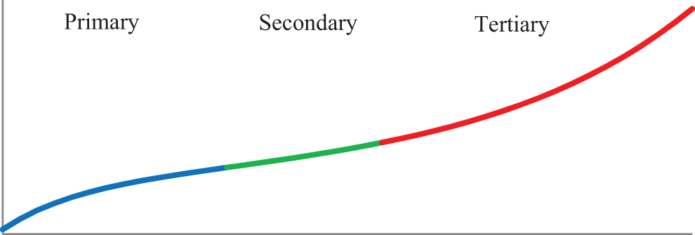
Classifications of creep behaviour. 1
The mechanism behind the primary creeping is the rearrangement of medium-sized polymer segments. During the secondary creeping phase, which is slower having short sequences, the side chains of the polymer chain are redistributed. During the tertiary creeping, first local micro-damage appears.
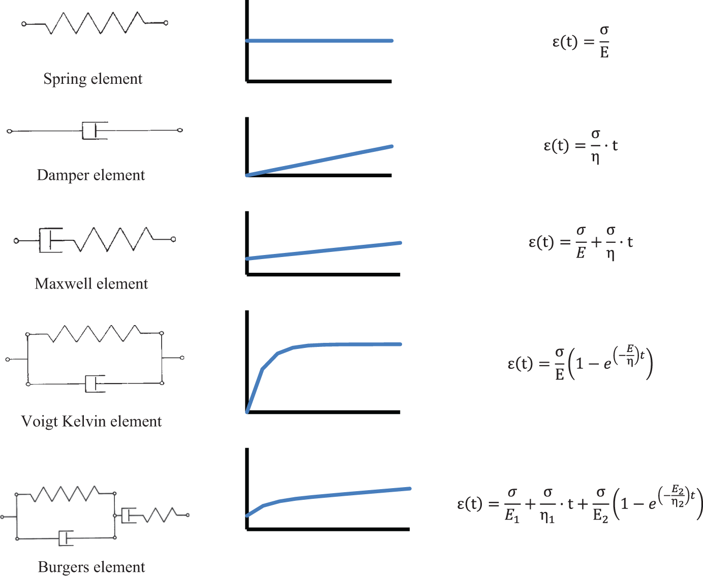
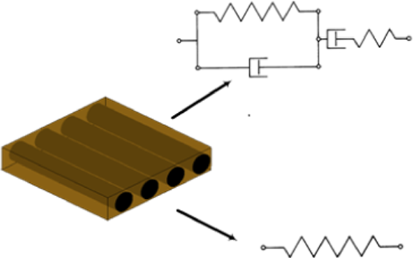
For the description of a viscoelastic problem, the integral or the differential form can be chosen. The differential form is presented, which is based on spring elements for the elastic part and damping elements for the viscoelastic part (Figure 2). Using different combinations of these basic elements, a complex time-dependent behaviour can be modelled, for example, by using a parallel connection of Maxwell elements. To enhance these simple linear viscoelastic models to a non-linear model, Leadermann 2 has published an approach that adds a load-dependent empirical function. This extension can be derived by tests at varying load levels.
Experimental characterization
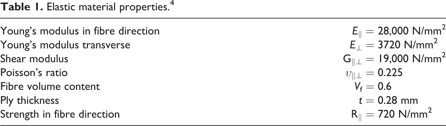
The used material in this study is a thermoplastic glass fibre-reinforced unidirectional system with a PP matrix. The PP matrix can be categorized as a bulk plastic and has suitable properties, such as excellent impact tolerance compared to thermoset matrices, a good ultimate strain performance and excellent chemical resistances. It can be used in rapid thermoforming processes with a cycle time of less than 2 min. One disadvantage of this semi-crystalline polymer matrix, in comparison with thermoset systems, is that there are no strong connections between the polymer chains composing the spatial arrangement. Therefore, this material has a higher tendency to creep. The plastic flow leads to a redistribution of the loads from the matrix to the reinforcement fibres, which is generally a positive effect. The effect can be adverse if no reinforcement exists, which can be the case in load transmission areas or between different plies if high transverse shear loads occur. Additionally, high fibre parallel compression stress can lead to fibre buckling and part failure. The used material in this study has the following elastic properties summarized in Table 1. 4
Elastic material properties. 4
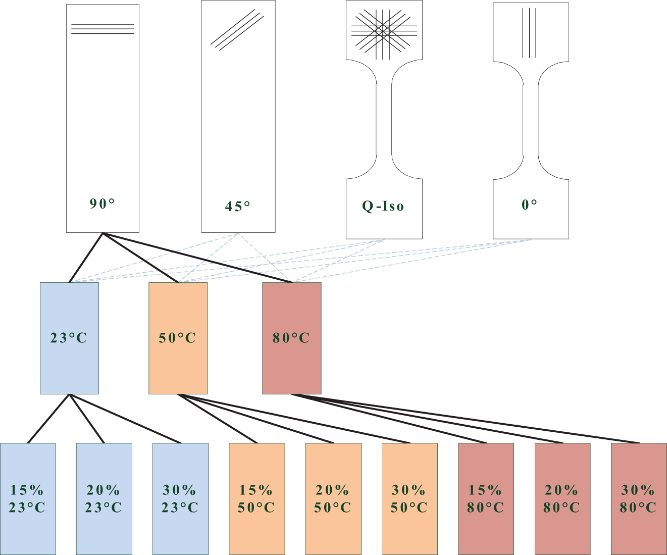
This composite material was tested in a creep test facility over the time of 144 h (1 week) at discrete load levels of 10, 20 and 30% of the material strength and at temperatures of 23, 50 and 80°C. This was chosen to determine the primary and secondary creep effect in dependency of temperature and load. The unidirectional material was tested in fibre direction, transverse to the fibre direction and in 45° direction. Additionally, a more complex unsymmetrical unbalanced lay up of [0/90/45/45] was tested. Figures 3 and 4 show the test equipment and the sampling plan. All tests are performed according to DIN EN ISO 899-1:2003. 12,13 Every test is repeated three times.
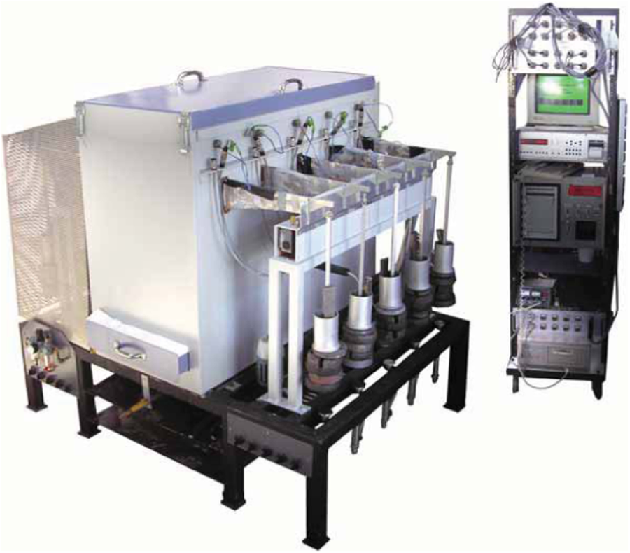
Creep test bed.
Perform end tests.
Figure 5 shows three strain–time curves of the material tested perpendicular to the fibre direction as a representative example. A detailed presentation of all the results will be presented in the validation chapter. The test was performed at 23°C at three different load levels of 15, 20 and 30% of the strength limit. Figure 5 shows the average curve of three tests.
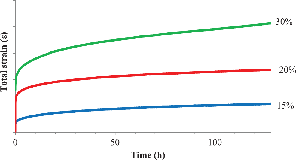
Isostress creep curves.
The experimentally measured results can be classified as primary and secondary creep phenomena. No significant visible tertiary creep occurred during the tests. Taking into account the classifications of viscous elasticity, the behaviour is not load independent. The creep velocity increases significantly due to the load level, and it has to be taken into account that the changes of the load level are relatively small. This non-linear effect is significantly increased by a rise of the test temperature. Therefore, a non-linear viscoelastic approach or the modified linear approach presented by Leadermann
2
should be used to model the materials behaviour. A comparison of the basic rheological elements shows that the Burgers model fits to the general shape of the creep behaviour. In summary, the following assumption can be made for the glass fibre-reinforced thermoplastic material: The behaviour of the materials is non-linear, viscoelastic and time, temperature and load level dependent. Primary and secondary creeping occurs (during the observation period). The general shape of the creep curve can be idealized using a Burgers model. The creep behaviour depends on the fibre orientation. No measurable creeping occurs in fibre direction. The creep behaviour due in transverse and 45° direction to the fibre is different.
Model development
An experimental database is used to derive two characteristic creep functions based on an extended Burgers model. In the second step, an interpolation method based on some aspects of the Puck criterion is used to predict the creep behaviour of a unidirectional ply for complex load case.
Derivation of characteristic creep curves
The first step for the development of a suitable model to analyse the creeping behaviour under different load and temperature conditions was the development of an extension of the burger model which incorporates these effects. Initially, it is necessary to distinguish between the elastic and the viscoelastic strain component:

where εtot(t) is the strain total, εel(t) is the strain increment elastic and εvis(t) is the strain increment creep. 9,10
The elastic strain is defined as follows:

where E(T) is the creep modulus and σ is tensor stress.
To describe the viscoelastic strain component, the experimental creep curves can be used in connection with the Burgers model, which is initially characterized by the following equation:

where
To incorporate the described dependency of the viscoelastic behaviour on the test conditions, the Burgers model is extended using the following equation. The values A n, B n, C n, D n and E n are used to fit the experimental creep curves for different temperature- and load-dependent conditions:

In the next step, the load dependency (σ n) is substituted by a dimensionless value eff, the material effort which is corresponding to the Puck failure index. 5 The idea behind this is explained in detail in the next section. As found in the experimental part of this study, the relevant creep curves are given by the experiment in 90° and 45° direction to the fibre since no creep is measured in fibre direction. Consequently, two parameter sets have to be found for the fitting parameter creep functions A n, B n, C n(T), D n(T) and E n(eff) from the given experimental database. As defined in the following set of equations, A n and B n are constant values, C n(T) is an exponential function dependent on temperature and D n,(T) and E n(eff) are second-order polynomial functions of temperature and load, respectively:


This set of functions is able to take into account the temperature variation from RT to 80°C and a load level up to 15% to 30% from the strength limits as shown later on in Figures 10 to 13. The necessary values of each parameter were found by parameter variations.
Creep curve interpolation
In the previous section, function sets for two characteristic creep curves for normal stress and shear stress load conditions were derived. The objective of this section is to describe a method that takes the different creep behavior for complex stress states into account. An interpolation method is needed, which incorporates the correct creep behaviour for the unidirectional material. The observed unidirectional material can be idealized as a transversely isotropic material. Accordingly, the creep behaviour can be simplified by assuming that no creep occurs in fibre direction, 6 and the in-plane behaviour normal to the reinforcement is equal to that in out-of-plane direction, whilst no distinction is made between shear stress components:


The next step describes the interpolation of the characteristic creep curves. Interpolation methods to transfer values that where experimentally obtained in a normal stress state to predict the behaviour under complex loads can be found in several failure criteria for composite materials, such as Hashin, Cuntze or Puck. Due to its physics-based nature, Puck’s fracture criterion for three dimensions (3-D) is seen as the most promising to apply to the creep problem. It was therefore investigated whether the method used to evaluate failure due to a complex stress state can also be used to predict the creep behaviour in a complex stress state.
In the first step of the Puck criterion for 3-D, all inter fibre failure relevant stress components are projected on a so-called fracture plane by the following functions to obtain a set of one normal stress components and two shear stress components. This projection is done by rotation around the fibre orientation (Figure 6).
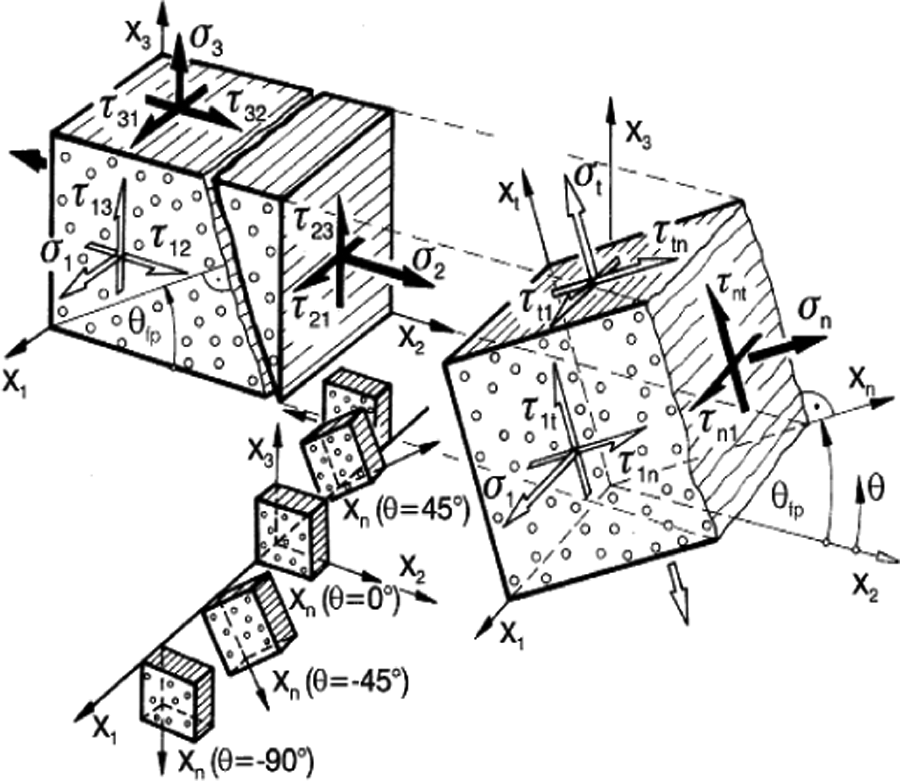
Stress projection. 5
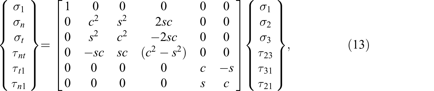
where c = cos(θ) and s = sin(θ); σ 1 is stress in fibre direction, σ n is normal stress on Pucks fracture plane and τ n, τ nt are shear stress on Pucks fracture plane. 8
Therefore, this approach reduces five stress components to only three components. In the next step, Puck computes a resulting vector, the material effort or failure index, from these three components. Puck assumes that a failure will occur at the fracture plane angle, where the material effort features a maximum. Accordingly, the projection on the fracture plane has to be performed iteratively for angles of rotation between 0° and 180° (assuming transverse isotropy).
On the fracture plane n with the normal stress component σ
n and the shear stress components τ
n and τ
n1, several simple operations based on geometrical relations can be performed to compute for example a resulting shear stress vector (Figure 7). The information about the direction, namely, the angle, of this resulting vector can be used to calculate the characteristic creep curves for shear between the known cases
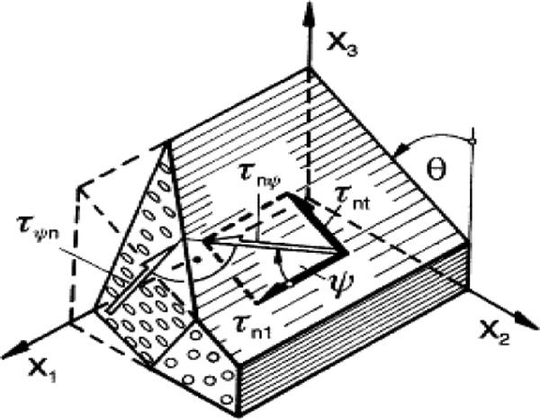
Fracture plane stress components. 5

where ψ is shear stress angle.
A similar approach can be used to interpolate between shear stress and normal stress (Figure 8):
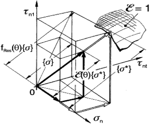
Vector of effort. 5

where θ is normal shear stress angle.
This leads to the following system of equations to interpolate between the two characteristic creep curves for a complex three-dimensional stress state 7,8 :


Numerical analysis
Model description
A parametric FE model was built for all four specimens of the experimental test set-up using the average geometries. The specimens are clamped on the lower side, and according to the strength limits, 15, 20 and 30% of the limit load level are applied on the upper side. The study was performed for temperatures of 23, 50 and 80°C (Figure 9).
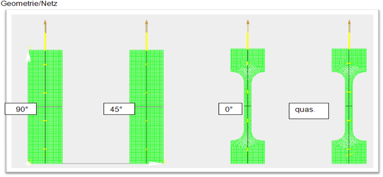
Finite element models.
The model is meshed using multilayer shell elements with a Mindlin–Reissner approach.
Results
Figures 10 to 13 show the experimental and numerical results in fibre direction, transverse to the fibre direction, in 45° direction and for the complex [0/90/45/45] lay up.
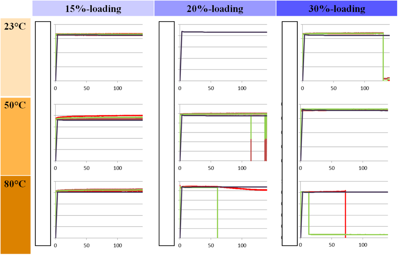
In fibre direction.
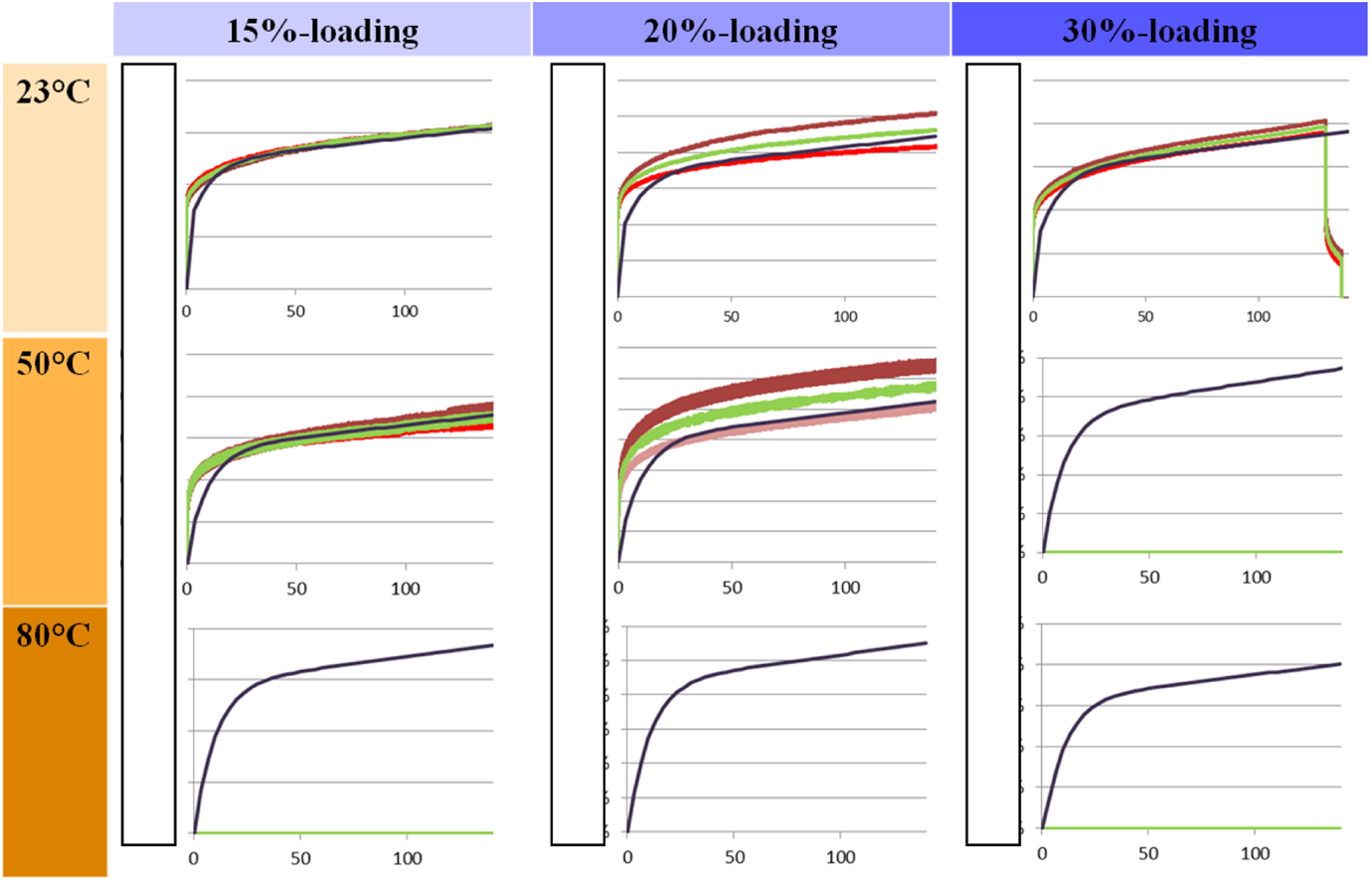
Transverse to the fibre direction.
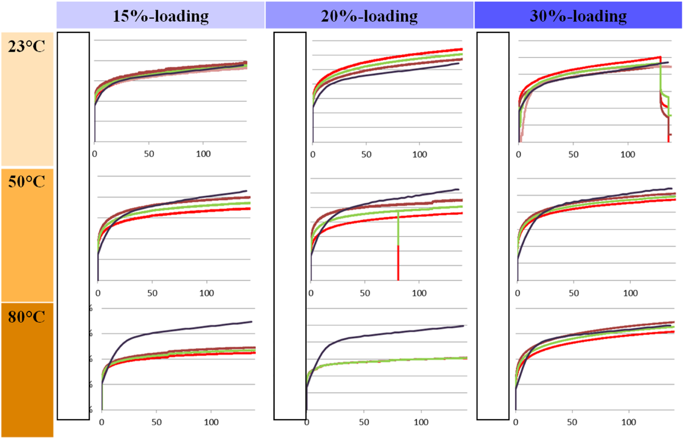
In 45° direction to the fibre.
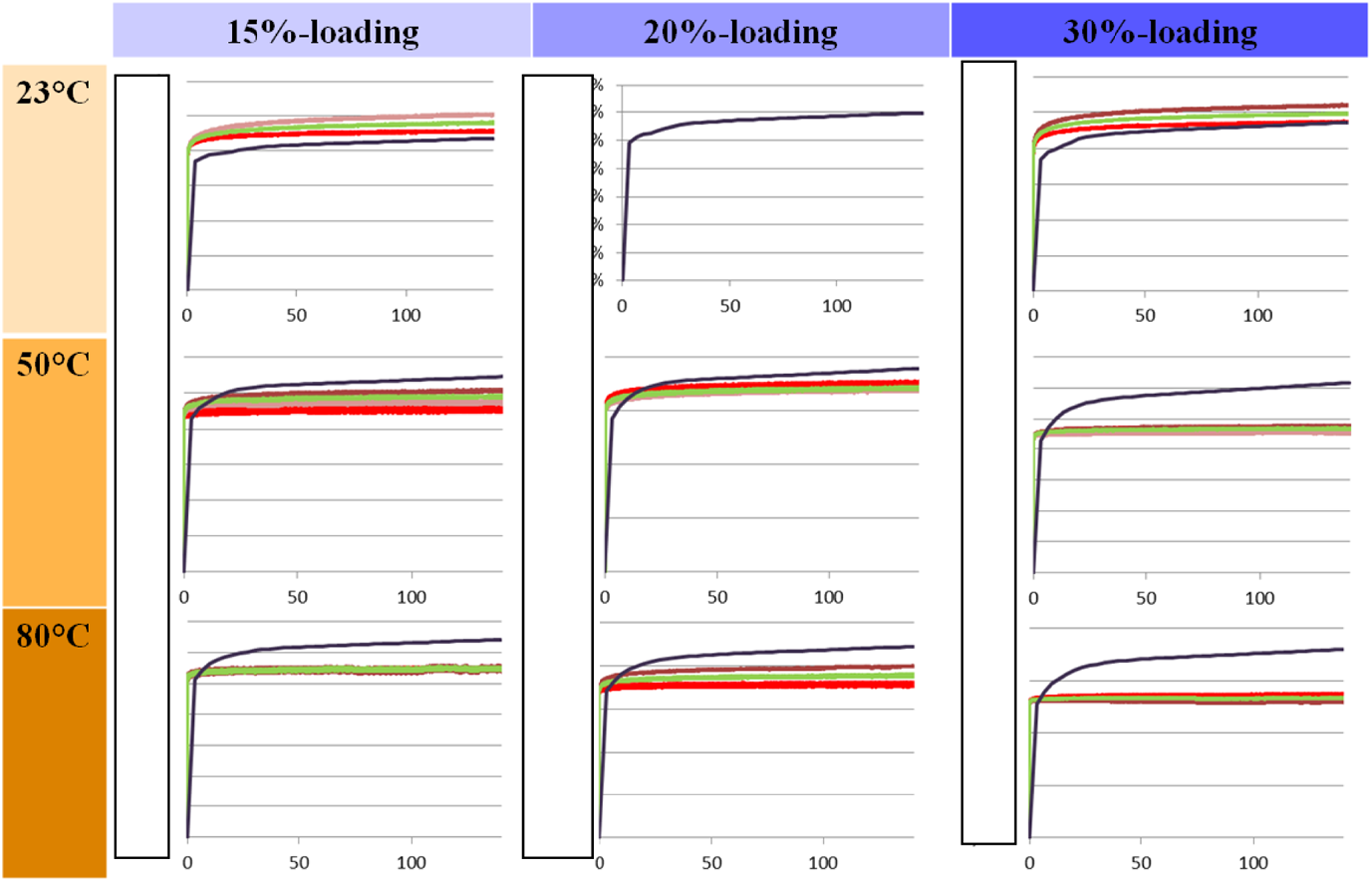
Complex laminate.
In fibre direction, no creeping was measured experimentally. The developed model shows a reliable result with no creeping in the range of application. The sudden changes in the experimental curves are due to specimen failure.
The predictions in transverse direction are also in good accordance with the experimental results. Unfortunately, no experimental results could be obtained at 80°C due to failure of all specimens. In this case, the presented approach has to be extended to account for damage/degradation. This means a limitation of the developed model to a temperature of max. 50°C for this material.
Figure 12 demonstrates the qualitative agreement between simulation and experiment for the 45° test case. In contrast to the 90° load case, the specimens did not fail at high temperatures. Whilst the accordance is sufficient at low temperature, the reliability of the model decreases with rising temperature.
The test case using the complex lay up is the validation test case and the proof of concept of the interpolation method and the developed model. The model is able to reproduce the behaviour at low temperature and low load levels. In case of high temperatures and high load level, the model starts to overestimate the creep strain. In the experiment, the viscoelastic creep strain component decreases compared to the low temperature/loads. There is a shift to a faster primary and less secondary creeping. Therefore, some other effects in the laminate occur, which might be based on changing of fibre orientations, clamping effects or other.
Table 2 summarizes the difference between model and experimental results at the investigated conditions.
Comparison test vs. experimental results.
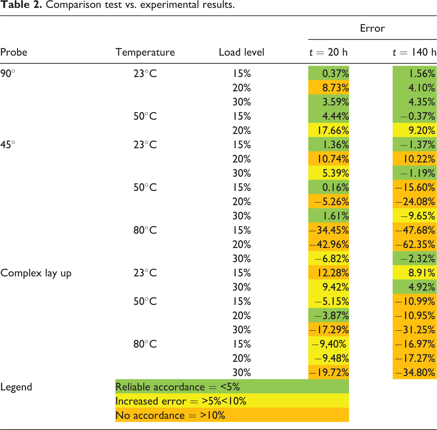
The developed approach was able to capture the physical behaviour in the range of 23–80°C and load levels of 15–30% of the strength limit. In case of uniaxial creeping transverse to the fibre, an average deviation of 6.9% after 20 h and 3.8% after 140 h was obtained. In case of 45° load direction to the fibre, an average deviation of 2.5% at 20 h and 9.6% after 140 h was achieved. The model was then applied to a complex lay up. In this case, a not uniaxial stress state is applied. In this case, an average accordance of 5.4% at 20 h and 13.5% after 140 h was obtained.
Conclusion
In this study, a thermoplastic glass fibre-reinforced material was investigated regarding its temperature and load-dependent creep behaviour. The unidirectional material shows a complex creep elongation with a non-linear, load level-dependent creeping, consisting (during the time period investigated) of primary and second creeping. The creeping behaviour is sensitive to the temperature and to the anisotropic characteristics of the material. Starting from these experimental results, two characteristic creep curves for normal stress condition transverse to the fibre and in-plane shear stress have been derived using an extended Burgers approach. An interpolation model between these characteristic creep curves was presented which is based on the ideas of the 3-D Puck criterion. The developed model was validated against the experimental data by comparing test at room temperature, 50°C and 80°C in combination with a load level of 15%, 20% and 30% of the strength limits and for fibre reinforcement orientations of 0°, 90° and 45°. The developed approach was able to capture the physical behaviour for all these conditions with an average deviation of 6.9% after 20 h and 3.8% after 140 h for transverse applied load and of 2.5% at 20 h and 9.6% after 140 h for 45° applied load. The model was then applied to a complex lay up. This validation shows reliability of the developed approach with an accordance of 5.4% at 20 h and 13.5% after 140 h. For the complex lay up, the accordance is not sufficient, and further research is needed to understand the creep behaviour in the laminate. The presented approach is, however, able to reliably represent the creep on the ply level. In addition, further investigation regarding the ability to extrapolate the behavior between 144 h of testing and the full lifetime of a structure are required to ensure the reliability of the developed approach.
Footnotes
Declaration of Conflicting Interests
The author(s) declared no potential conflicts of interest with respect to the research, authorship, and/or publication of this article.
Funding
The author(s) received no financial support for the research, authorship, and/or publication of this article.