
Abstract
The damage formation in a multilayered armor system without and with an interlayer (rubber, Teflon, and aluminum foam) between the front face ceramic layer and the composite backing plate were investigated experimentally and numerically. The projectile impact tests were performed in a low-velocity projectile impact test system and the numerical studies were implemented using the nonlinear finite element code LS-DYNA. The results of numerical simulations showed that the stress wave transmission to the composite backing plate decreased significantly in Teflon and foam interlayer armor configurations. Similar to without interlayer configuration, the rubber interlayer configuration led to the passage of relatively high stress waves to the composite backing plate. This was mainly attributed to the increased rubber interlayer impedance during the impact event. The numerical results of reduced stress wave transmission to the backing plate and the increased damage formation in the ceramic front face layer with the use of Teflon and foam interlayer was further confirmed experimentally.
Introduction
Layered structures are widely employed in structures subjected to impact loading to mitigate the stress wave propagation. An example of such structures is composite armor, also known as integrated composite armor. Composite armor is constituted by two layers of materials, each functioning differently. The front face’s hard ceramic layer deforms the projectile severely, gradually reducing the kinetic energy of the projectile and the resultant pressure developed on the composite backing plate. The ceramic layer is commonly constructed of tiles because the tiles facilitate the easy replacement of damaged sections. The second layer, the composite backing plate, absorbs the remaining kinetic energy of the projectile by matrix and fiber fracture, fiber–matrix debonding, and microbuckling. In order to understand the intricate stress wave transmissions and reflections from and in between the layers and interfaces of the composite armor, analytic and numerical investigations have been carried out previously, examples of which can be found in literature. 1 –4 Since the replacement of a continuous composite backing plate is rather difficult, the reduction of the pressure developed and the damage formed on the composite backing plate is of paramount importance. The insertion of a low impedance interlayer including rubber, 5,6 aluminum foam, 7 and thick adhesives 8 –10 between the ceramic and composite layer increased stress wave reflections to the front layer and distributed the load to a wider area of the composite backing plate and hence reduced the damage formation in the composite backing plate. Furthermore, rubber interlayer was reported to retain the fragmented ceramic tiles attached to it after the projectile impact, increasing the multi-hit capability. 5 In a previous study, the present authors showed both experimentally and numerically that the insertion of Teflon and aluminum foam interlayers significantly reduced the stress wave transmission to the composite layer when impacted with an armor-piercing projectile. 11 Meanwhile, the experiments with armor-piercing projectiles come with several drawbacks, even if it represents the real threat to the armor. Firstly, the obliquity of the impact varies between each test, leading to different types of damage formation in the layers tested at similar projectile velocities. Secondly, the recovery of the fractured and shattered ceramic tiles is not always possible. Although attaining very high impact velocities is difficult using a laboratory scale projectile impact test system, it provides better control of the test variables and makes it possible to recover the fragmented ceramic pieces in a confined chamber. In this study, the stress wave propagations in a composite armor were investigated with the same configurations as reported by Tasdemirci et al. 11 at relatively low impact velocities using a laboratory scale projectile impact test system. The effect of interlayer thickness on damage formation was also investigated numerically based on an equal areal density. Aluminum foam interlayer configuration was selected as the baseline: the interlayer thicknesses were then changed accordingly to obtain the same areal density in all configurations. For the case of without interlayer configuration, the thickness of the composite layer was increased to attain the same areal density as for the interlayer configurations.
Experimental
The low-velocity projectile impact test system used in the experiments is shown in Figure 1. The experimental setup consisted of a pressure vessel, triggering valve, sabot, barrel, and target chamber. The projectile was guided in the barrel using a polyurethane foam sabot (18 g) (Figure 1(a)). The pressure vessel propelled the projectile against the target, which was firmly fixed on the target frame inside the impact chamber (Figure 1(b)). The initial projectile velocity was measured using a laser barrier located at the front of the target in the impact chamber (Figure 1(c)). The residual velocity of the projectile was measured in the same setup by means of a laser barrier placed at the back of the target, when perforation occurred in the test. The projectile was an AISI E52100 steel sphere, 12.7 mm in diameter and 8 g in weight. The mass of the projectile was close to that of a 7.62 mm M61 type AP projectile core.
(a) Projectile impact test setup, (b) target frame, and (c) laser barriers.
The front face of the tested armor plate (250 × 250 mm2) was constructed of 25 square-shaped alumina ceramic tiles (Bitossi Corbit 98) of 50 × 50 × 5 mm3 in size (Figure 2(a)).
(a) Multilayer armor target and (b) finite element model of the projectile and target.
The continuous composite backing plate was 14 mm thick and prepared by vacuum-assisted resin transfer molding using 30 layers of plain weave E-glass fabric with an areal density of 0.6 kg/m2 and having a [0/90] ply orientation (i.e. the fabric warp direction is at 0° and the weft direction is at 90°). The thicknesses of the ethylene propylene diene monomer (EPDM) rubber (Shore A60), Teflon (PolarchipTM, a trademark of W. L. Gore, Inc., Newark, Delaware, USA) and aluminum metal foam (0.438 g/cm3) interlayers were, respectively, 1.5, 2, and 14 mm.
The steel projectile was fired from a 5 m distance with a velocity of 200 ± 5 m/s. The multilayered armor configuration without interlayer was also impact tested for comparison. Following the impact tests, the tested plates were cut across using a diamond saw and the damage formation in the subsequent layers was observed visually. In all tests, no perforation of the composite backing plate occurred, while the front face ceramic layer fractured but remained attached to the composite backing plate or interlayer material after the test.
Modeling
The numerical models of the tested armor configurations were implemented in the finite element code of LS-DYNA 971. 12 The multilayered armor test plate (Figure 2(a)) was modeled using a full model with no additional symmetry definition (Figure 2(b)). The numerical model shown in Figure 2(b) consisted of spherical steel projectile and fixed multilayer armor test sample. The armor tile was fixed (both translations and rotations were prevented) with a 3 cm width zone around its outer edge to simulate the target frame fixation of test sample. The projectile impacted the sample at a velocity of 200 m/s.
The AISI E52100 steel projectile was modeled using the Johnson–Cook (JC) flow stress model.
13
The equivalent stress in the JC flow stress model

where, A, B, n, C, and m are the material model parameters and
Johnson–Cook material model parameters for spherical steel projectile. 14
The Johnson–Holmquist II (JH-2) 15 material model, a pressure- and strain–rate-sensitive material model developed for representing the high strain rate constitutive behavior of dense ceramics, was used to simulate damage formation and dynamic failure of the ceramic layer. In this material model, a definition of the intact and fractured strength, a pressure–volume relationship that can include bulking, and a damage model that transitions the material from an intact state to a damaged state are included. The normalized equivalent stress for the strength is:

where,

and the normalized fracture stress is given as:

where P∗, T∗, and
where

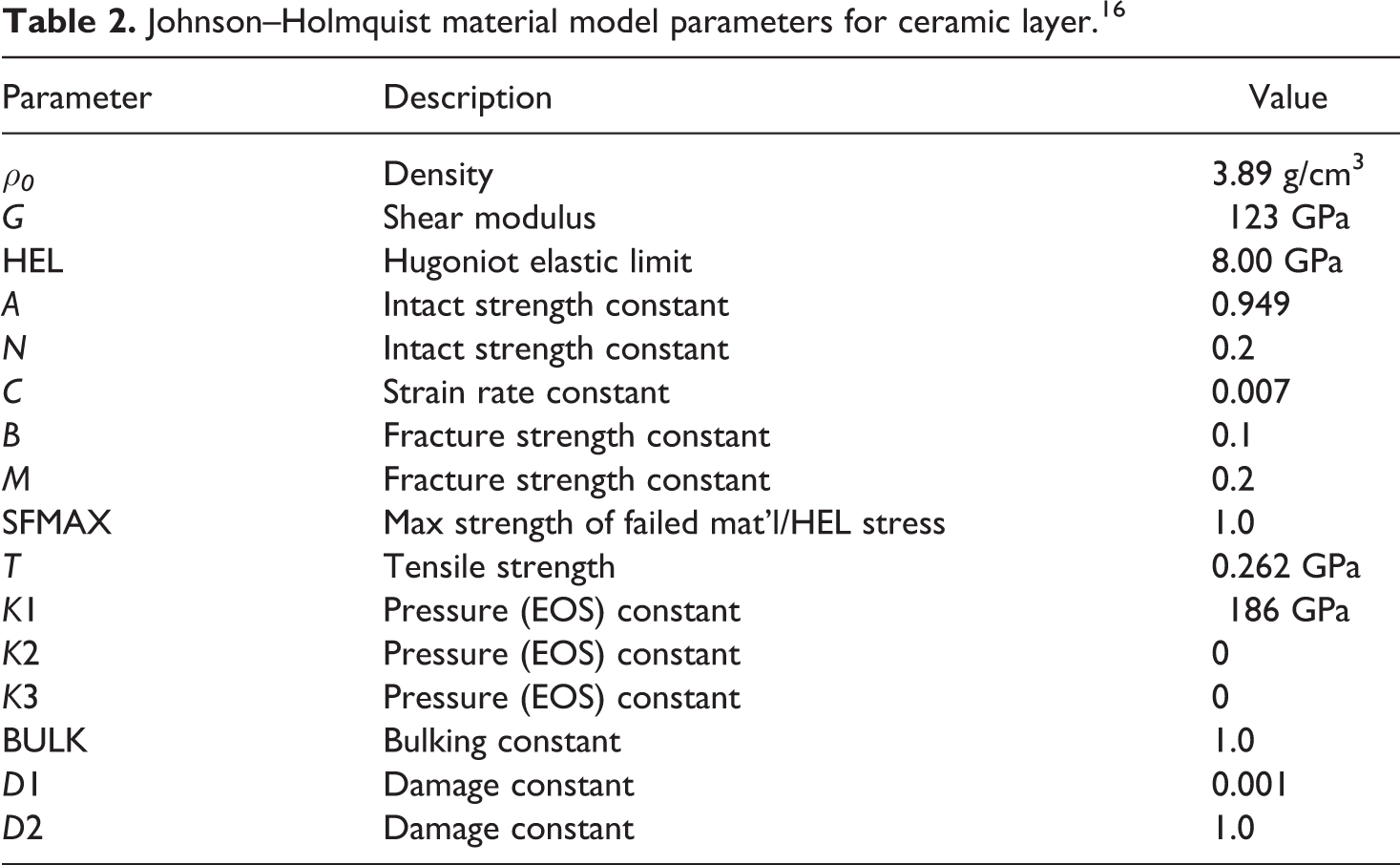
where D 1 and D 2 are damage constants. The material model constants of alumina ceramic used in the model were taken from the work by Krashanitsa and Shkarayev 16 and are tabulated in Table 2.
Johnson–Holmquist material model parameters for ceramic layer. 16
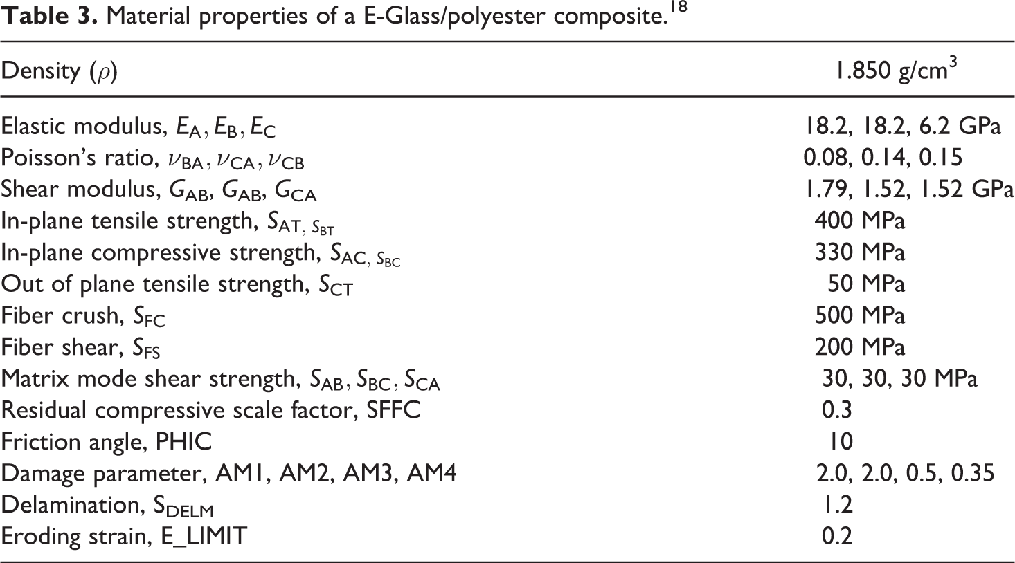
The E-glass/polyester composite layer was modeled (30 layers) with MAT162 (MAT_COMPOSITE_DMG_MSC) material model. 12 The material model MAT162 is based on the Hashin’s failure criteria, 17 which allows the user to monitor the initiation and progression of different failure modes including tensile and compressive fiber failure, fiber crush, matrix failure, and delamination. Element erosion is also taken into account in the material model. The material model parameters of E-glass/polyester composite were taken from the work by Tunusoglu et al. 18 and are tabulated in Table 3.
Material properties of a E-Glass/polyester composite. 18
The rubber interlayer was modeled with the Ogden material model. 19 In this material model, the rubber is considered to be fully incompressible since its bulk modulus greatly exceeds shear modulus. Rate effects are also taken into account through linear viscoelasticity.
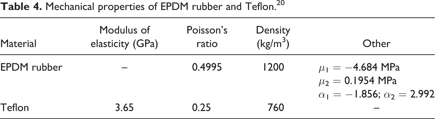
The Teflon interlayer was modeled with the crushable foam material model. This material model is dedicated to the modeling of crushable foams with optional damping and tension cutoff. The unloading is fully elastic and tension is treated as elastic—perfectly plastic at the tension cutoff value. The material model constants of EPDM rubber and Teflon were taken from the work by Tasdemirci and Hall 20 and are tabulated in Table 4.
Mechanical properties of EPDM rubber and Teflon. 20
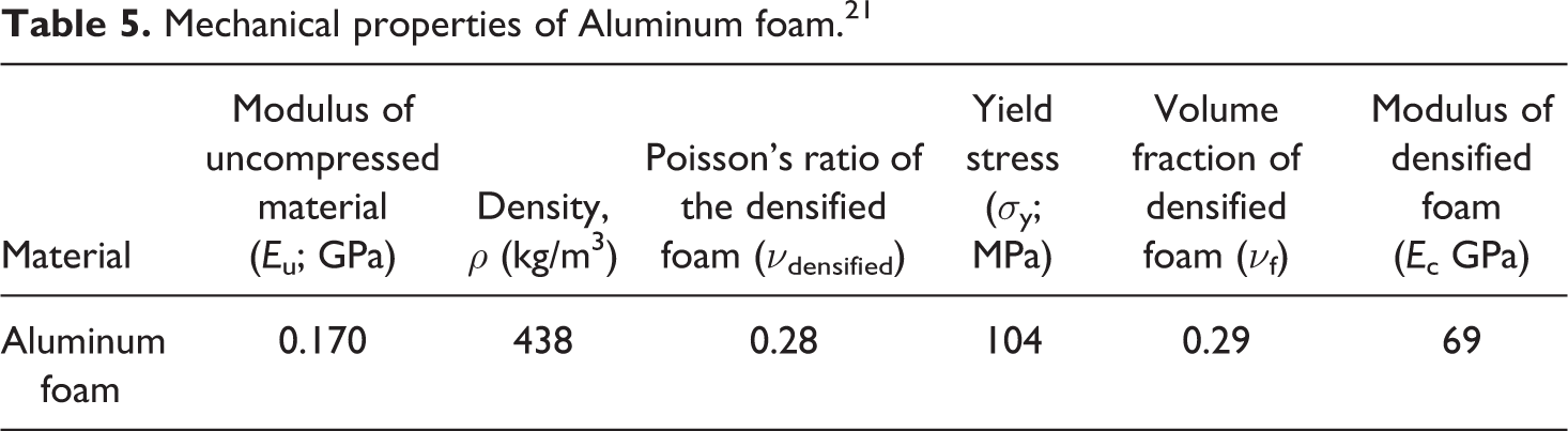
The aluminum foam was modeled with the MAT_HONEYCOMB material model. 12 In this model, the behavior is assumed to be orthotropic before compaction and the stress tensors are uncoupled with zero Poisson’s ratio. The normal and shear load displacement curves can be defined as input. However, shear load–displacement curves are not always readily available, and it is assumed that the shear stress is the half of normal stress. 7 The shear and elastic moduli of the compacted foam vary linearly and constantly increase to those of the bulk material with respect to the relative volume. The material model constants of the aluminum foam were taken from the work by Ergonenc 21 and are tabulated in Table 5. In the Ogden, the crushable foam and the MAT_HONEYCOMB material models, the stress–strain curves, 20,21 were used as input and the least squares fit to the experimental stress–strain curves were applied during the initialization phase.
Mechanical properties of Aluminum foam. 21
The armor and projectile were modeled using eight-node solid elements with single integration point. Eroding surface to surface contact was used to define the contacts between all contacting surfaces. There was no initial gap and bonding defined between the tiles and the interlayers. For the element failure on the exterior surfaces, additional eroding contact options were defined. In the model, the elements do not contribute to the dynamics of penetration when the effective plastic strain attains a predefined limit. The interface between the layers is redefined automatically when erosion starts. The mesh sensitivity of the used model was previously checked by varying the element sizes of the projectile and the layers. In accord with this, a minimum element size of 0.5 mm in the impact zone was chosen. 11 The coding of the tested armor configurations is as follows: without interlayer, with rubber (WR) interlayer, with Teflon (WT) interlayer, and with aluminum foam (WF) interlayer. Besides these, three additional configurations having the same areal density as the WF interlayer configuration were also modeled. In these configurations, the thicknesses of the rubber and Teflon interlayers were increased from 1.5 mm to 5.1 mm (WR51) and from 2 mm to 8 mm (WT8), respectively. For the without interlayer configuration, the thickness of the composite was increased from 14 mm to 17 mm (WO17) in order to have the same weight as for the WR51 and WT8 configurations.
Results and discussion
In the experiments and simulations, no perforation of the targets was detected. Figure 3(a) and (b) shows, respectively, the evolution of projectile residual velocity and projectile residual mass with time for the simulation of the seven investigated different armor configurations. The projectile velocity declines steeply approximately within the first 20 μs for all configurations approximately to 12 m/s for WT, to 10 m/s for WF, to 5 m/s for WR51 and WT8, and to 3 m/s for WO, WO17, and WR interlayer configurations as shown in Figure 3(a). For all the configurations investigated, the projectile shatters and breaks into small fragments and after approximately 100 μs, the velocity of fragments stabilize. Similar to the residual velocity, the projectile erosion is rapid approximately with the first 20 μs for all configurations as seen in Figure 3(b). Following the initial rapid rate of erosion, the erosion starts to slow down gradually. Since the numerical code still erodes the elements of the projectile in contact with the target even after the velocity of the projectile decreases significantly, a slight delay occurs between the times at which the projectile velocity and the projectile mass stabilize. The smallest erosion is seen in the WR configuration, while the largest erosion is seen for the WR51 interlayer configuration. Intermediate projectile erosions are seen in WT, WO, WO17, WT8, and WF interlayer configurations between WR51 and WR interlayer configurations.
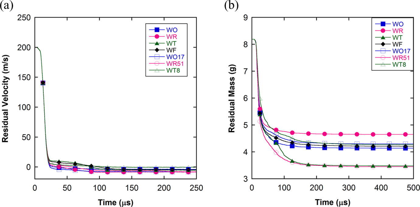
Numerical projectile: (a) residual velocity and (b) residual mass versus time.
Figure 4 shows the numerical force–time (through-thickness) history in the projectile impact direction at the interlayer–composite interface. It is noted in the same figure that in both cases without interlayer (WO and WO17) and rubber (WR and WR51) interlayer configurations, the force transmitted to the composite layer increases rapidly to a maximum approximately in the first 20 μs. It is also noted in the same figure that the increase in the composite plate thickness has no significant effect on the stress wave transmission. The rapid increase in the force transmitted to the composite layer in rubber interlayer configurations is due to the increased rubber stiffness during the course of deformation and increasing the thickness of rubber interlayer from 1.5 mm to 5.1 mm is not effective in reducing the stress wave transmitted to the backing plate. The stiffness of the rubber interlayer increases as it is radially constraint by the neighboring material. A similar result was previously reported for the rubber interlayer in a similar composite armor by Gama et al. 5,6 However, the Teflon and foam interlayer significantly reduce the force transmitted to the composite plate, and approximately in the first 20 μs almost no force is transmitted to the composite layer as seen in Figure 4. The filtering effect of the interlayer materials on the pressure transmission to the composite plate was also previously reported for an aluminum foam interlayer between a ceramic and a composite layer. 7 The highest force transmission occurs in without (WO and WO17) and rubber interlayer (WR and WR51) configurations (approximately 130 kN) and the lowest in the WT8 interlayer configuration (approximately 3 kN). Opposite to the rubber interlayer, the increase in thickness of the Teflon layer, from 2 mm to 8 mm, results in a reduction and a delay in the stress wave transmission. The highest force transmission in the WF interlayer configuration is 25 kN at 80 μs. The filtering capability of the Teflon interlayer is noted to be higher than that of aluminum foam for the investigated interlayer thicknesses and for the same areal density. The reduced force transmission to the composite backing layer in Teflon and WF interlayer configurations also confirms the increased force reflections from the interlayer to the ceramic layer.
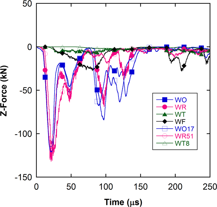
The numerical variation of the through–thickness force component with time at the interlayer-composite interface.
Figures 5(a) to (c) shows sequentially the total internal, kinetic, and eroded internal energy histories of ceramic layer. In accordance with the above-mentioned criteria, the ceramic layer shows higher total internal energy for Teflon (WT and WT8) and WF interlayer configurations and lower internal energy for rubber and without interlayer configurations (Figure 5(a)). The internal energy of the ceramic layer sequentially decreases from Teflon interlayer (WT8 and WT) to aluminum foam interlayer (WF), rubber interlayer (WR and WR51), and without interlayer (WO and WO17) configurations. The numerical simulations do not indicate a significant effect of increasing the thicknesses of both the rubber and Teflon interlayers on the internal energy of the ceramic layer. The kinetic energy transferred to the ceramic layer by the projectile in the Teflon and aluminum foam interlayer configurations is also significantly greater than that of the rubber and without interlayer configurations as shown in Figure 5(b). The eroded internal energy basically indicates the projectile kinetic energy dissipation through deformation and erosion. As shown in Figure 5(c), Teflon and aluminum interlayer configurations are also more efficient than rubber and without interlayer configurations in terms of eroded internal energy. However, the increase in the thickness of both rubber and Teflon interlayers results in reduced eroded internal energy of ceramic layer.
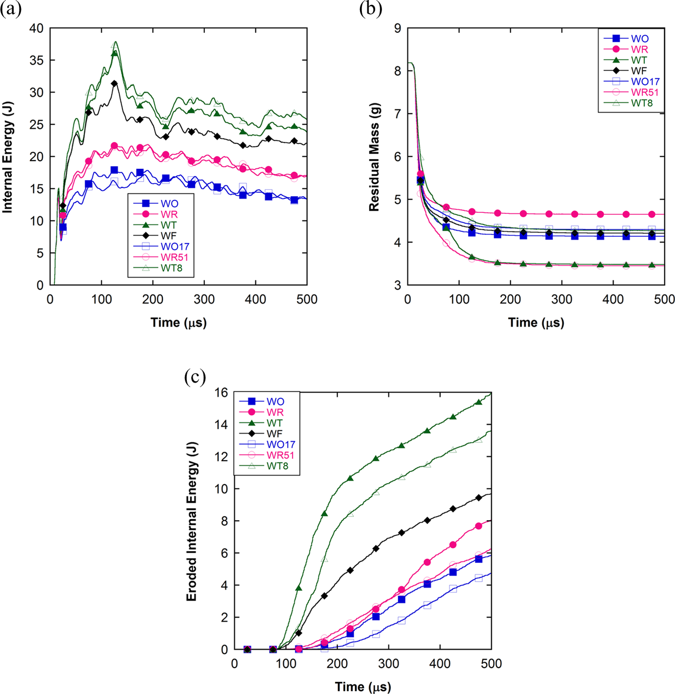
The numerical energy histories of the ceramic layer: (a) internal energy, (b) kinetic energy, and (c) eroded internal energy.
The total internal and kinetic energy of the composite layer, as opposite to the ceramic layer, are higher in the rubber and without interlayer configurations than those in the Teflon and aluminum foam interlayer configurations as shown in Figures 6(a) and (b). The higher internal energy in the composite layer of rubber and without interlayer configurations in fact shows the higher stress transmission to the composite layer. For the WT8 case, both total internal and kinetic energy of the composite layer remained at significantly lower values.
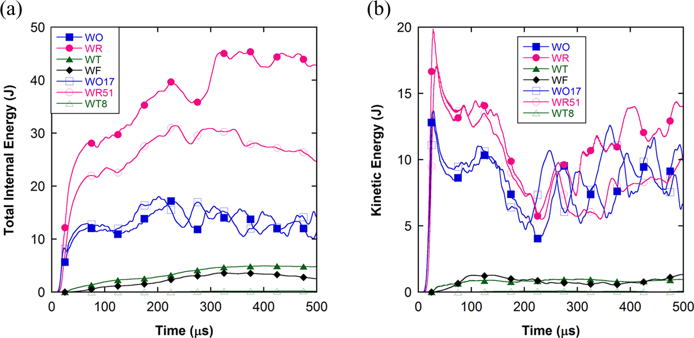
The numerical energy histories of the composite plate: (a) total internal energy and (b) kinetic energy.
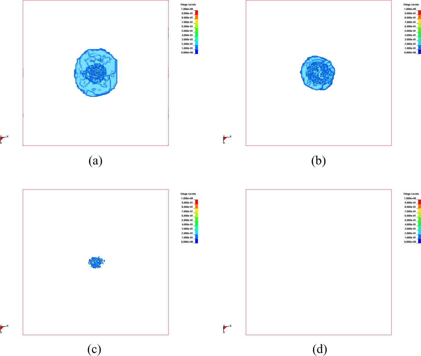
Figures 7(a) to (d) shows sequentially the damage contours of the ceramic layer in WO, WR, WT, and WF interlayer configurations. In all configurations, the impact damage in the ceramic layer is localized around the projectile impact zone. It is noted that the damage in the ceramic layer in WO and WR interlayer configurations is constraint within the impacted ceramic tile (Figure 7(a) and (b)), while the ceramic damage in WT and WF interlayer configurations spreads laterally to neighboring tiles (Figures 7(c) and (d)). The spreading of the ceramic layer damage in WT and WF interlayer configurations indicates that the load transferred to the composite backing plate is distributed over a larger area, which is preferable in designing armors with multilayer materials. The damage formation in the ceramic layer of WO17 and WR51 configurations is limited to the center tile right under the projectile impact zone (Figure 8(a) and (b)), similar to the WO and WR configurations.
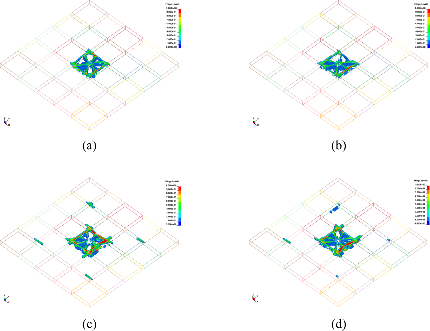
Damage contours in the ceramic layer 500 μs after impact: (a) WO, (b) WR, (c) WT, and (d) WF configuration. WO: without interlayer; WR: with rubber interlayer; WT: with Teflon interlayer; WF: with aluminum foam interlayer.
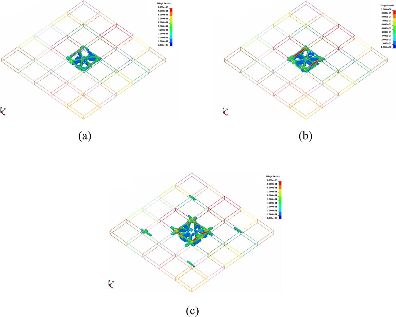
Damage contours in the ceramic layer 500 μs after impact: (a) WO17, (b) WR51, and (c) WT8 configuration. WO: without interlayer; WR: with rubber interlayer; WT: with Teflon interlayer.
As the dimensions of each ceramic tile were comparable with the diameter of the projectile, it was not possible in the experiments to hit the target right at the center of middle tile. Figure 9(a) to (d) shows the pictures of the ceramic tiles after impact in WO, WR, WT, and WF configurations, respectively. From the photos of the edge-shot WO and WR configurations seen in Figure 9(a) and (b), it is possible to conclude that the WO configuration ceramic layer fragments into larger size pieces. A similar comparison can also be made for the center-shot WT and WF configurations seen in Figures 9(c) and (d). The number of radial cracks emanating from the projectile impact zone of the WF configuration is seen to be higher than that of the WT configuration. These observations are in close agreement with the numerically determined damage contours in the ceramic layer.
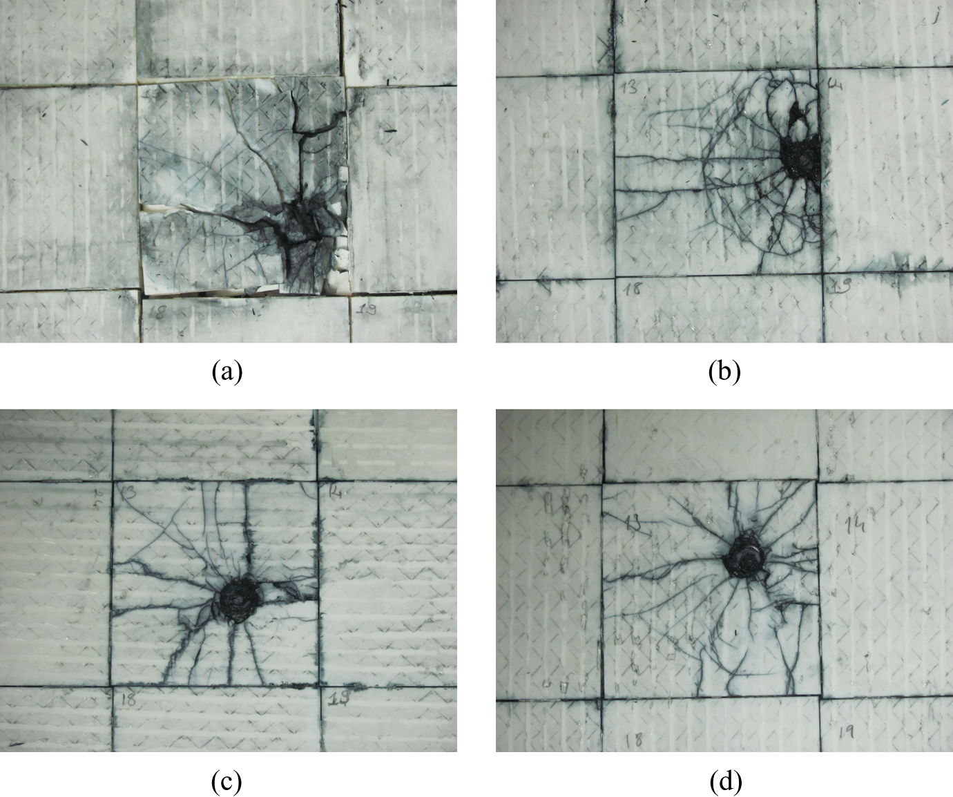
The pictures of the ceramic tiles after impact in (a) WO, (b) WR, (c) WT, and (d) WF configuration. WO: without interlayer; WR: with rubber interlayer; WT: with Teflon interlayer; WF: with aluminum foam interlayer.
Figure 10(a) to (d) shows the delamination damage area in the composite backing plate in WO and WR, WT, and WF interlayer configurations, respectively. The delaminated area of the composite layer is visually observed to be localized around the top outermost plies. The delamination damage in the composite layer is relatively smaller in the WT interlayer configuration (Figure 10(c)) than those in the WO and WR interlayer configuration (Figures 10(a) and (b)). However, in the WF interlayer configuration, no visible delamination is observed (Figure 10(d)).
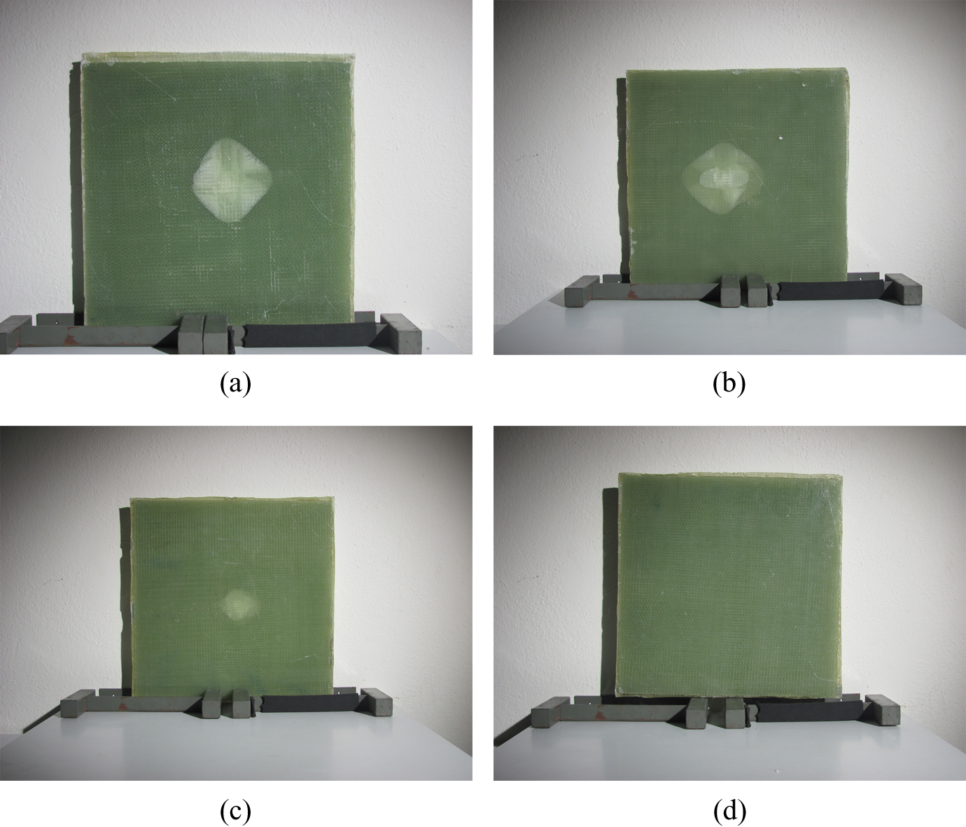
The back-face views of the composite backing plate after impact: (a) WO, (b) WR, (c) WT, and (d) WF configuration. WO: without interlayer; WR: with rubber interlayer; WT: with Teflon interlayer; WF: with aluminum foam interlayer.
Figure 11(a) to (d) show the corresponding numerically observed delamination damage in WO and WR, WT, and WF interlayer configurations, respectively. Numerical results are in excellent agreement with those of experimental. Damage is significantly lesser in WT interlayer configuration (Figure 11(c)) and no composite damage is seen in WF configuration (Figure 11(d)).
Delamination damage contours in the composite layer 500 μs after impact: (a) WO, (b) WR, (c) WT, and (d) WF configuration. WO: without interlayer; WR: with rubber interlayer; WT: with Teflon interlayer; WF: with aluminum foam interlayer.
Figure 12(a) to (c) shows the numerical delamination damage in WO17, WR51, and WT8 interlayer configurations, respectively. As can be seen from Figures 12(a) and (b), the thickness increase in both no interlayer and rubber interlayer configurations do not result in a significant effect on the damage formation in the composite plate. However, increasing the Teflon interlayer thickness in the WT8 configuration leads to no damage in the composite plate (Figure 12(c)). This also confirms the reduced stress wave transmission to the composite backing plate with increasing Teflon interlayer thickness from 2 mm to 8 mm.
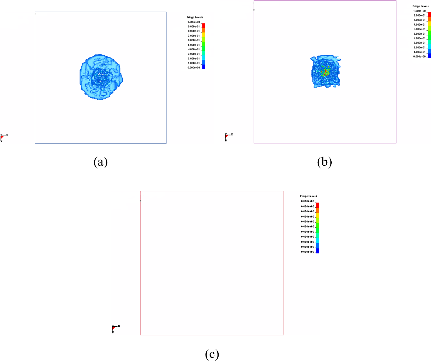
Delamination damage contours in the composite layer 500 μs after impact: (a) WO17, (b) WR51, and (c) WT8 configuration. WO: without interlayer; WR: with rubber interlayer; WT: with Teflon interlayer.
These results clearly indicate the importance of the interlayer material and its thickness in the composite armor design. The interlayer significantly alters the damage initiation and propagation in the ceramic layer. Similar results were also found for the same armor configurations of larger test samples tested using armor-piercing projectiles at a relatively high impact velocity, 11 while more controlled and lower impact velocity tests were conducted in the present study using a laboratory scale impact test system. Two effects of interlayer materials on the response of the composite armor are detected. The presence of a low-impedance interlayer decreases the force developed on the composite backing plate and lead to fragmentation and spreading of the damage in the ceramic layer. The fragmentation of the ceramic layer is caused by the reflection of the compressive stress waves at the ceramic–interlayer interface due to the acoustic impedance mismatch induced by the interlayer. The lateral spreading of the damage zone is favorable in reducing the transmitted stress to the composite backing plate as previously noted in a study in which the use of thicker layers of adhesive between ceramic and backing aluminum plate resulted in stress distribution over a wider area of aluminum plate. 10 Present results gave some essence on the effect of interlayer on damage formation at a low impact velocity using a laboratory-scale projectile impact test system.
Conclusions
The effect of interlayer material on the stress wave propagation behavior of a multilayered armor without and with low impedance interlayers was investigated experimentally and numerically using a low velocity projectile impact test system. The used test system allowed the recovery of the fragmented ceramic layer. Numerical results showed that the interlayer material had a strong influence on the stress propagation and the fragmentation of the ceramic layer and damage formation in the composite backing plate. Teflon and aluminum foam interlayers greatly reduced the stress wave transmission to the composite backing plate and increased the damage on the front ceramic layer. It was found that the impedance of the rubber interlayer increased rapidly at the beginning of the projectile impact and lead to relatively higher stress transmission to the composite backing plate, similar to without interlayer configuration. The reduced stress transmissions to the backing plate and increased damaging of the ceramic layer with the use of Teflon and aluminum foam interlayer were confirmed experimentally by observing the damage formed in the composite backing plate visually.
Footnotes
Acknowledgment
The authors thank Dr. Ian W. Hall and W.L. Gore & Associates Inc. for provision of the Teflon (Polarchip™) interlayers and Mr. Francesco Panza from Colorobbia/Turkey for supplying ceramic layers.
Declaration of Conflicting Interests
The author(s) declared no potential conflicts of interest with respect to the research, authorship, and/or publication of this article.
Funding
The author(s) disclosed receipt of the following financial support for the research, authorship, and/or publication of this article: The authors would like to thank the Scientific and Technical Council of Turkey (TUBITAK; grant no. 106M353) for providing financial support.